Article

Study on Supersonic Dehydration Efficiency of High Pressure Natural Gas

1
College to Electromechanical Engineering, Qingdao University of Science and Technology, Qingdao 266061, China
2
College of Chemical Engineering, Qingdao University of Science and Technology, Qingdao 266042, China
3
Nanjing Tica Thermal Technology Co. Ltd., Nanjing 210038, China
*
Author to whom correspondence should be addressed.
Sustainability 2020, 12(2), 488; https://doi.org/10.3390/su12020488
Submission received: 29 November 2019 / Revised: 24 December 2019 / Accepted: 6 January 2020 / Published: 8 January 2020
(This article belongs to the Special Issue Process Integration and Optimisation for Sustainable Systems)

Abstract

:
Supersonic cyclone separator is a novel type of natural gas dewatering device that overcomes the shortcomings of traditional dewatering methods. In order to investigate the factors affecting the separation efficiency and improve the separation performance of the supersonic cyclone separator, the discrete particle model was employed in numerical calculation. On the basis of an accurate numerical model, the flow field of supersonic cyclone separator was analyzed, the trajectories of droplets were predicted, and the factors affecting the separation efficiency of droplets were investigated. The numerical results indicated that Laval nozzle could provide the necessary conditions for the condensation of water vapor. The swirler can throw droplets onto the wall or into the separator, both of which are foundations for realizing the separation of droplets. Droplets had three typical trajectories affected by centrifugal effect and inertia effect. The existence of a shock wave increases the swirl intensity of droplets, which is conducive to the separation of droplets. The diameter of droplets should be increased as much as possible in order to improve separation efficiency, and the gas–liquid area ratio should be about 45.25%, and the number of vanes should be 10.

1. Introduction

With the development of society and the improvement of environmental protection requirements, natural gas, as a clean energy, plays an increasingly important role in energy consumption [1]. The sustainable development of natural gas will be an important part of future research. Natural gas extracted from oil and gas fields needs dewatering treatment before the gathering and transportation process [2], otherwise the pipeline will be blocked and corroded [3]. Traditional dehydration technologies such as triethylene glycol dehydration [4], membrane separation dehydration [5], molecular sieve dehydration [6] and expansion refrigeration dehydration [7] have many problems, which include the need for additives, complex process, high equipment investment and operation costs, and the addition of hydrate inhibitors. Especially, the addition of hydrate inhibitors can cause secondary pollution in severe cases. Supersonic cyclone dewatering technology is a new type of natural gas dewatering technology that integrates condensation and separation functions [8]. It has attracted scholars because of its many advantages, such as simple and compact structure, high reliability, no chemical additives, and minimal investment [9] and maintenance costs [10]. Supersonic cyclone separator will be an inevitable choice for the sustainable development of the natural gas industry.
Gas–liquid separation efficiency is one of the most important parameters for evaluating the overall performance of the supersonic cyclone separator [11]. The higher the gas–liquid separation efficiency, the better the overall performance of the supersonic cyclone separator [12,13]. Studying the factors affecting the separation efficiency of the supersonic cyclone separator is conducive to the structural optimization of the device and the improvement of its performance and promotes the application of this technology in natural gas dehydration. The flow process of natural gas to be treated in a supersonic cyclone separator is very complex, including the unsteady turbulent flow process of compressed gas, gas phase transition process, gas–liquid cyclone flow process, and gas–liquid separation process [8]. In different flow processes, the factors affecting gas–liquid separation efficiency in supersonic cyclone separators are also different.
The condensation depth of gas and the centrifugal force acting on droplets are two key factors that affect the separation efficiency of supersonic cyclone separator. The condensing efficiency of condensed gas increases with the condensing depth, which indirectly improves the separation efficiency of the supersonic cyclone separator [14]. Centrifugal force is caused by the effect of a swirler on the droplets condensed by condensable gas. The greater the centrifugal force on the droplets, the easier the droplets can be thrown to the wall to achieve separation [15]. The separation efficiency of the supersonic cyclone separator improves directly [16]. At present, the research on improving the separation efficiency of the supersonic cyclone separator mainly focuses on these two aspects.
Ma et al. [17] carried out an experimental study to improve the separation performance of a supersonic cyclone separator for the treatment of gas mixture with a single heavy component. The method of adding a condensation core to enlarge droplets was employed, which improved the performance of the supersonic cyclone separator in experiments. Hu et al. [18,19] thought that increasing the pressure loss could obtain higher separation efficiency by experimental study. This is because the lowest temperature and the lowest pressure in the supersonic nozzle are increased by increasing the pressure loss, which provides a better condensation environment for the gas and helps to improve the condensation depth of the gas. Similar conclusions are also reflected in Bian’s research [20]. When inlet pressure is 600 kPa and pressure loss ratio is 47.5%, the improved supersonic separator has a good cooling and separation performance. Cao and Yang [21], Wen et al. [22], Yang et al. [23], Liu [24] and Eriqitai et al. [25] also confirmed this viewpoint that pressure loss was close to the separation performance of supersonic cyclone separator.
Some scholars studied the influence of centrifugal force on the supersonic separation efficiency of droplets, which mainly focused on droplet size and swirl intensity. The size of droplets will affect the quality of droplets [26], and then affect the centrifugal force on droplets [27]. According to Newton’s law of mechanics, the larger the droplet size is, the greater the centrifugal force is. Swirl intensity referrs to the ratio of tangential velocity to the axial velocity of droplets. The greater the swirl intensity is, the greater the centrifugal acceleration of the droplet is. Centrifugal force plays a dominant role in controlling the movement of droplets. The larger the centrifugal acceleration is, the more easily the droplets are thrown to the wall, and the higher the separation efficiency is. [28].
At present, some scholars have studied other factors affecting the separation performance of supersonic cyclone separators. Malyshkina [29] proposed a procedure employed for primary estimation of the efficiency of purification of natural gas in a supersonic separator depending on the Mach number under the following conditions: the initial temperature of 250–300 K and the initial pressure of 6000 kPa. Jiang et al. [30] studied the separation mechanism of CO2 droplets and natural gas in a supersonic separator. The results showed that there was an obvious restriction relation between the pressure and tangential velocity distribution caused by the swirl blade; a balanced point (optimized structure) was necessary to achieve the purpose of condensation and separation of CO2 droplets.
The structure of the supersonic cyclone separator also has an important influence on the separation performance. Yang et al. [31] studied a set of static vanes employed as the swirling flow generator in the supersonic cyclone separator for gas purification application taking into consideration the balance between the expansion characteristic and swirling separation performance. The swirl angle, height and number of the static vane had an important influence on the purification effect of natural gas. Wen et al. [32] studied the effect of diffuser structure on the separation performance of supersonic cyclone separator. The results showed that the conical diffuser with high pressure recovery performance is a good choice for the supersonic separator. However, in this aspect, the specific numerical value of the structure of influence on separation efficiency was not reflected, but indirectly and generally showed that the structure had an important influence on the supersonic cyclone separator.
The aim of this research was to study the factors affecting the separation performance of a supersonic cyclone separator by the discrete particle model. The flow field in a supersonic cyclone separator was analyzed and the trajectories of droplets were predicted so that the influence of structure on separation efficiency could be studied more intuitively and accurately. This research could not only explore the factors affecting the separation of droplets, but also provide a method for optimizing the overall structure of supersonic cyclone separator.

2. Numerical Methods

2.1. Gas phase Governing Equations

The equation of the continuity can be described as:
ρ g t + ρ g u g = m g
where ρg is the gas density; ug is the gas velocity; t is the time; and mg is the mass of liquid droplet into gas phase.
The momentum equation can be described as:
t ρ g u g + ρ g u g u g = p + r + F
where p is the static pressure; F is the force of the discrete phase particles on the gas flow; r is the stress tensor;
Among them,
r = μ u g + u g T 2 3 u g I
where μ is the aerodynamic viscosity; I is the unit tensor;
The energy equation is presented as follows:
t ρ g E + ρ g E + p u g = k T + r u g + S h
where E is the total energy; T is the static temperature; k is the heat transfer coefficient; and Sh is the heat transferred from the droplets to the gas flow.

2.2. Liquid Phase Governing Equations

In a supersonic cyclone separator, the movement of the droplet is mainly controlled by drag force and other forces. The equation of the droplet motions can be described as:
d u l d t = F D + F O
where ul is the particle speed; FD is mass drag force in units for particles; and FO is other forces, including gravity, thermophoretic force, Brownian force, and shear force (Saffman lift force) [33].
Among them
F D = 18 μ g ρ l d l 2 C D R e 24 u g u l
where ρl is the particle density; dl is the particle diameter; and Re is the relative Reynolds number, which is defined as:
R e = ρ g d l u l u g μ g
where CD is the drag coefficient and can be described as:
C D = a 1 + a 2 R e + a 3 R e 2
In the above equation, a1, a2 and a3 are constants that apply to smooth spherical particles over several ranges of Re [34].
In the supersonic cyclone separator, the influence of centrifugal force is much greater than the gravity, so the influence of gravity can be ignored. The thermometric force is mainly produced by radiation, which is not considered in this paper. Due to the turbulent movement of the particle, Brownian force can be also ignored. The fluid in the supersonic cyclone separator has a strong shear flow, and the shear effect of the rotation is strong enough to produce a strong shear lift. Therefore, Saffman lift force is mainly considered in the calculations. It can be described as:
F O = F S = 2 K v g ρ g d i j ρ l d l d l k d k l 0.25 u g u l
where FS is Saffman lift force; K = 2.594; dij is the deformation tensor; and νg is the dynamic viscosity.

2.3. The Supersonic Cyclone Separator Geometry
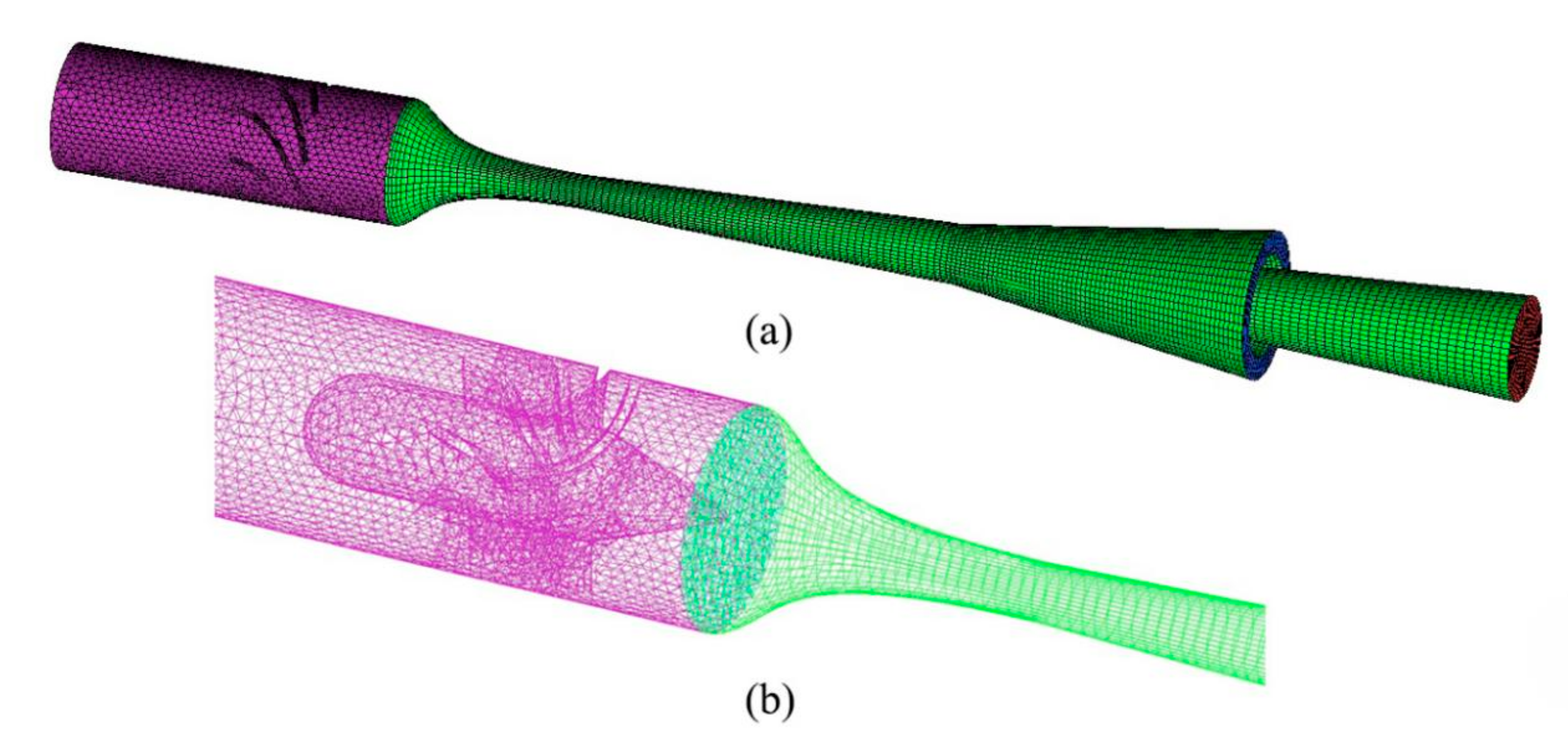
The structure of the supersonic cyclone separator is shown in Figure 1a, and the specific size is shown in Figure 1b. Where D1 is the inlet diameter of Laval nozzle, D1 = 20.4 mm; D2 is the throat diameter of Laval nozzle, D2 = 5.3 mm; D3 is the outlet diameter of Laval nozzle, D3 = 9.5 mm; D4 is the outlet diameter of dry gas, D4 = 18 mm; L1 is the length of Laval nozzle, L1 = 210 mm; L2 is the length of contraction section of Laval nozzle, L2 = 30 mm; and L3 is the length of diffuser, L3 = 217.5 mm. As for the structural parameters of the swirler, they can be found in the previous study of the group [35].

2.4. Mesh Strategy

In the supersonic cyclone separator, the gas enters the Laval nozzle after the swirler and reaches the sonic speed in the throat, so the supersonic speed of the gas is reached in the expansion section of the Laval nozzle. Therefore, the velocity gradient of gas in the throat of the Laval nozzle is high, and the grid needs to be encrypted to ensure the calculation accuracy. The grids are divided by ICEM CFD 16.0 (The Integrated Computer Engineering and Manufacturing code for Computational Fluid Dynamics). Due to the complex structure of the cyclone, structured grids and unstructured grids are employed to discretize geometric models, as shown in Figure 2.
The number of grids in the solution zone has a significant effect on the calculation results and can neither be too little nor too much. Too few grids cannot guarantee the accuracy of calculations. Too many meshes can improve the accuracy of the calculation results, but will increase iterations and the solution time. The supersonic cyclone separator is meshed with the mesh numbers of 923426, 1137824, 1315811, and 1532740, respectively. As the Laval nozzle is one of the most important components of the supersonic cyclone separator, the pressure changes of the section with x = 120 mm and x = 150 mm are taken as references to verify the grid independence. As a result of the grid independent verification, 1315811 cells or so were employed to discretize the flow domain, as showed in Figure 3.

2.5. Solving Methods and Boundary Conditions

For the gas phase, the finite volume method and the second order upwind method were employed to discrete governing equations. The k-epsilon model was employed in the viscous model, and the standard wall functions were utilized in near-wall treatment. The coupling of velocity field and pressure field was based on SIMPLE algorithms. For droplets, it was mainly affected by Saffman lift force in the flow field. The droplet was assumed to be diluted in the flow field, and the shape of the droplets was assumed to be spherical. The diameter distribution of droplets obeyed the uniform rule.
According to the flow characteristics of supersonic compressible gas, the boundary conditions of the inlet and outlet were set as pressure boundary conditions. The absolute pressure was used in numerical calculations, and the inlet pressure and outlet pressure were 13.2 MPa and 8.5 MPa, respectively. The stationary wall and the shear condition of no slip were selected as the wall boundary conditions. In order to calculate the trajectory of droplets, the boundary condition of the droplet was set as: Outlet was set to escape, that is, when the droplets reached the outlet of the gas, the tracking of the droplet was stopped. The boundary conditions of the liquid outlet and separator wall were set as “trap”. After entering the separator, droplets collided with the wall or reached the liquid outlet, all of which were considered to be captured. When droplets reached other walls, they were considered to be completely reflective after collision with the wall.

2.6. Model Verification

In order to verify the accuracy and reliability of the numerical model, operational parameters, geometric models, and experimental data of Jiang et al. [36] were employed. The data of Laval nozzle operating parameters are shown in Table 1. In the supersonic condensation experiment system, the transverse section of the Laval nozzle was designed to be a rectangular section. The equation of the Witozinsky curve was employed to design the contraction section of the Laval nozzle, and the expansion section of the Laval nozzle was designed by the equal expansion rate method, all of them are illustrated in Figure 4. Where R1 was the inlet diameter, R1 = 28mm; R2 was the throat diameter, R2 = 4 mm; R3 was the outlet diameter, R3 = 28.65mm; l1 was the length of the steady flow section, l1 = 30 mm; l2 was the length between the inlet and throat, l2 = 50mm, l3 was the total length of the Laval nozzle, and l3 = 300 mm.
The numerical results of the pressure along the axis were compared with the experimental data, as shown in Figure 5. The numerical results were basically consistent with the experimental data, but there are some deviations between them. This was mainly due to the spontaneous condensation of moist air in the Laval nozzle and the release of latent heat, which made the expansion process deviate from the isentropic expansion process. In the numerical verification, the medium employed was dry air, and the condensation effect of moist air was not taken into account, so that the condensation process decreased along the isentropic expansion line, resulting in a certain deviation between the numerical results and the experimental data. All in all, numerical validation showed the accuracy of the numerical model employed in this paper. Therefore, the numerical method could be employed to analyze the flow field in supersonic cyclone separators.

3. Results and Discussions
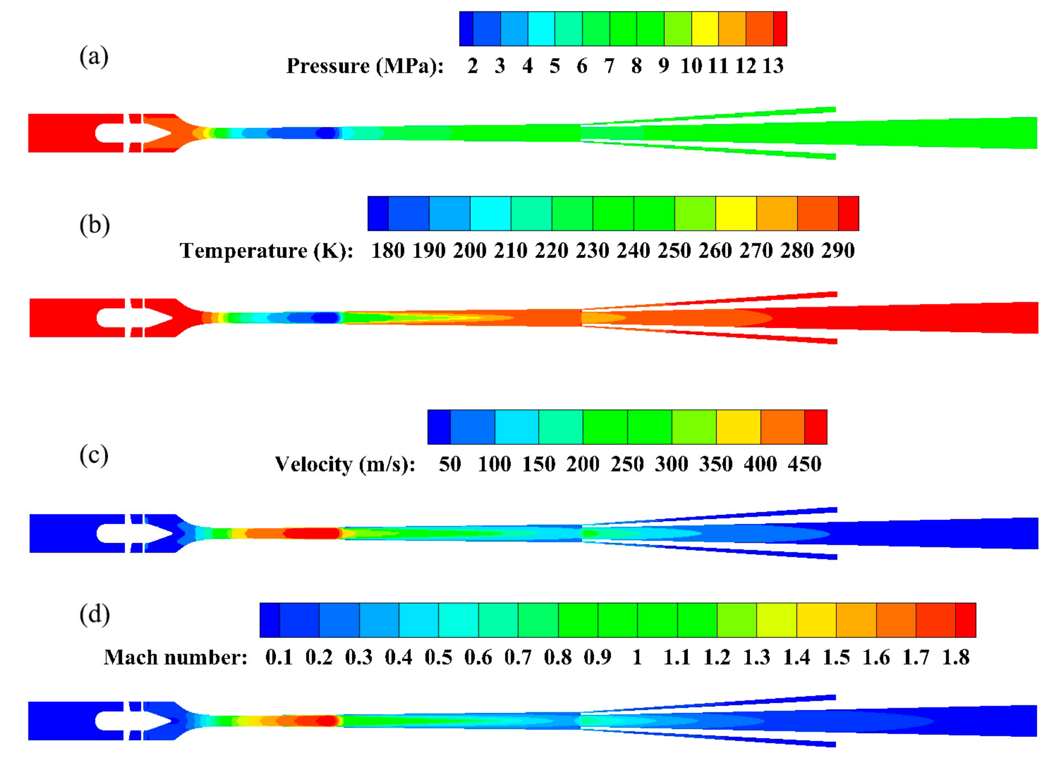
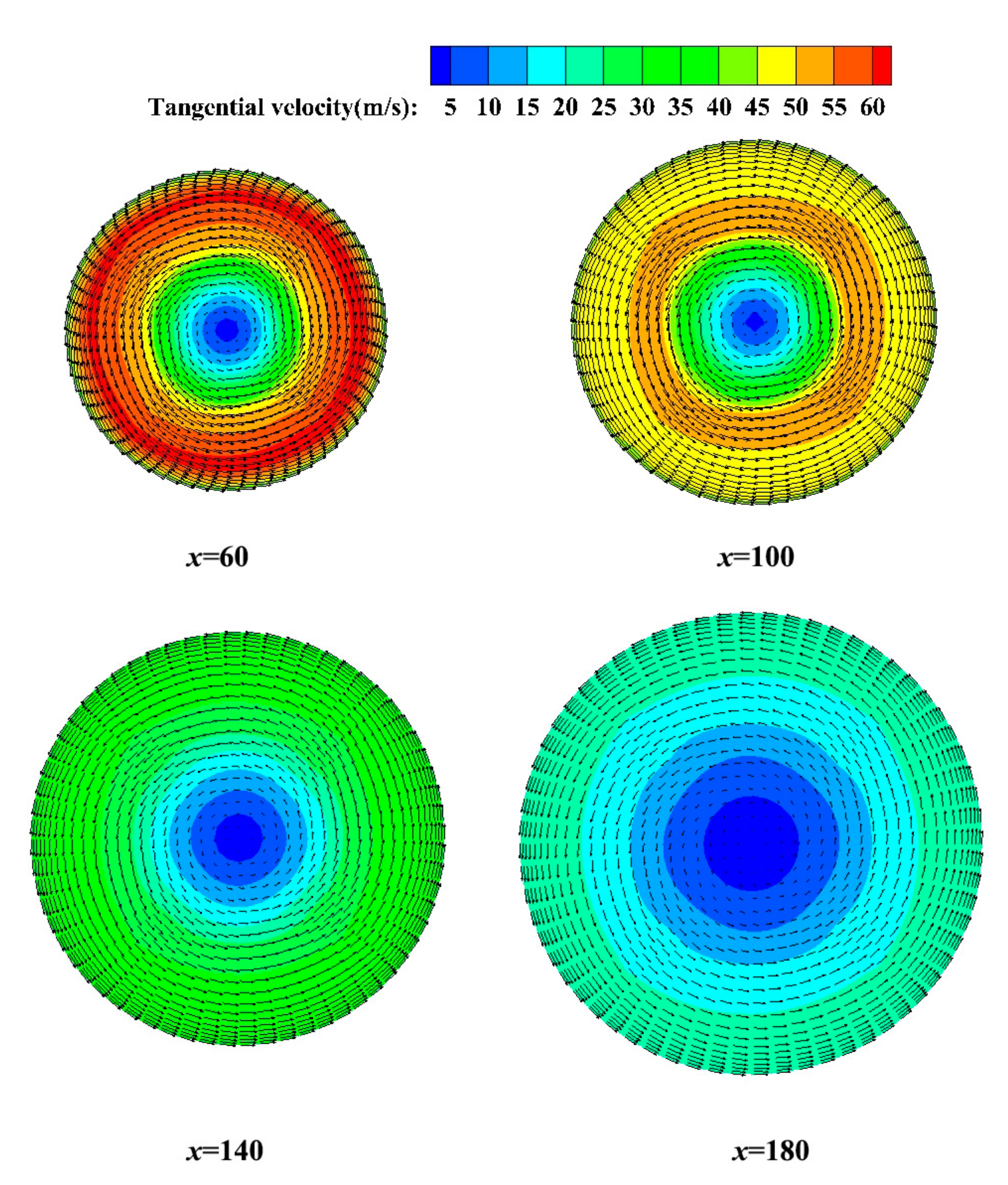
3.1. Gas Flow Field

Methane and water were employed as an example of numerical study. The gas flow field in the supersonic cyclone separator is shown in Figure 6. When the gas entered the Laval nozzle, the gas was smoothly compressed due to the gradual decrease of the flow area. The gas reached a critical state in the throat, and the Mach number was 1, forming a sonic flow. After reaching the throat, it expanded to form supersonic flow. The maximum Mach number was about 1.8, as shown in Figure 6d. When the gas was compressed and expanded, the change of static pressure and static temperature were accompanied by the transformation of energy. At the contractive section of the Laval nozzle, the static pressure and the static temperature decreased slowly. After reaching the throat, the static pressure and static temperature of the gas declined rapidly due to further adiabatic expansion of the high-pressure gas, forming the area of low temperature and low pressure, as shown in Figure 6a,b. The minimum static pressure was about 2 MPa, and the lowest static temperature was about 180 K. In the process of the sharp drop of the temperature of the Laval nozzle, the gas in the supersaturated state began to condense spontaneously, followed by the phenomenon of nucleation of droplets. The velocity of the fluid in the Laval nozzle was increasing, and its maximum velocity was about 450 m/s, which could be illustrated in Figure 6c. The time that the fluid stayed in the Laval nozzle was very short (merely a few milliseconds) and was an unbalanced transient process. In the Laval nozzle, a shock wave appeared at x = 100, as shown in Figure 6. When the shock wave occurred, the kinetic energy of the gas changed into potential energy, and the pressure and temperature rose. The process of swirling flow and spontaneous condensation of the fluid in the Laval nozzle laid the foundation for the separation of gas–liquid.
In the Laval nozzle, the droplets formed by the spontaneous condensation of the gas were thrown to the wall under tangential velocity, which realized the separation process of the gas–liquid. As shown in Figure 7, under the action of the swirler, the gas entering the Laval nozzle moved downstream in a swirling way. In this paper, the acceleration of the fluid at the x = 180 section near the Laval nozzle outlet was about 1.4 × 10⁶ m/s2, which ensured the centrifugal force required for the separation of the gas–liquid. Along the expansion section, the radius of rotation of the gas increased gradually, which resulted in the tangential velocity of gas gradually decreasing, according to the law of conservation of angular momentum. Therefore, in the actual design, the length of the Laval nozzle should be reasonable, not only to ensure enough length to meet the condensation time, but also not too long to reduce centrifugal acceleration.

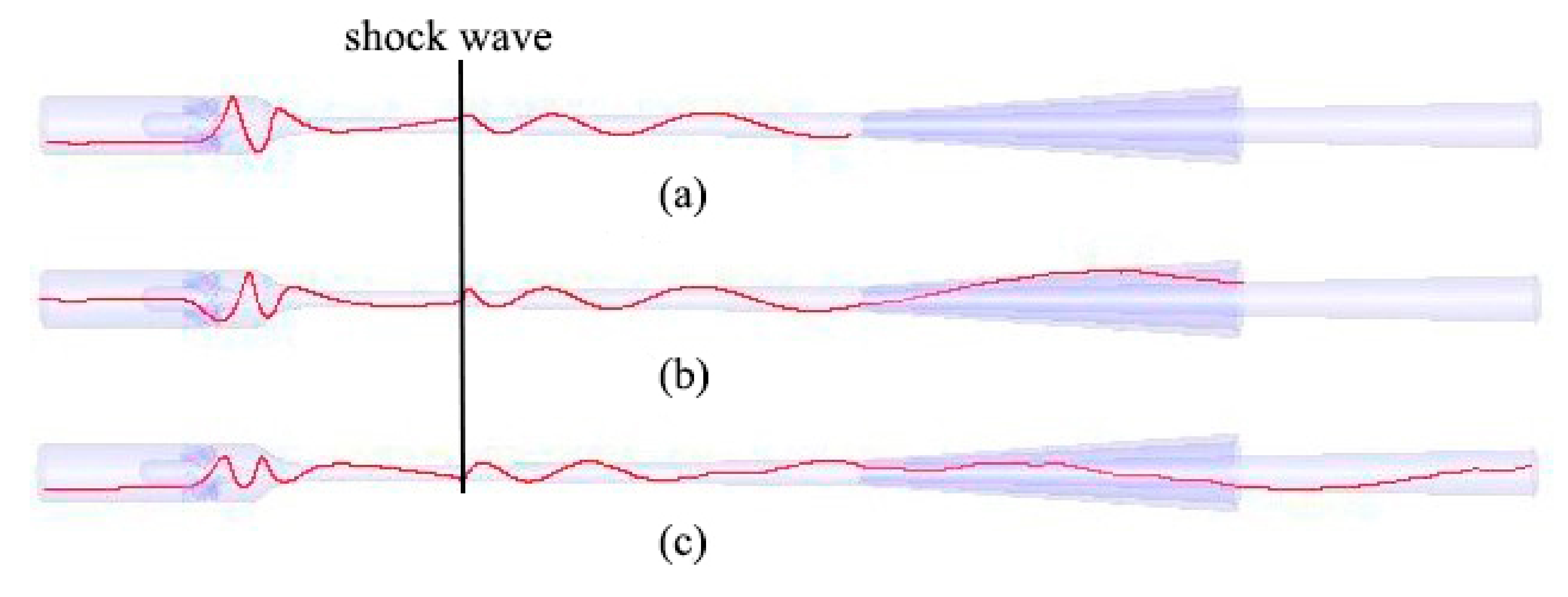
3.2. Droplet Trajectory

In fact, droplets condensed from supersaturated gas first appeared in the expansion section of the Laval nozzle. However, in order to conveniently predict the trajectory of droplets and study the separation factors that affected the separation efficiency of the separator, it was assumed that the spherical droplets entered the supersonic cyclone separator from the inlet of the device in the numerical model. After the droplets passed through the swirler, it would move along the axial direction with the influence of centrifugal force. In the same flow field, the centrifugal force of droplets of different sizes was different, so the trajectories in the flow field were different. For the droplets caught in the study, there were three typical trajectories, as shown in Figure 8. When the centrifugal effect of droplets was greater than the inertial effect caused by the axial velocity, that is, when the motion of droplets was mainly affected by centrifugal force, droplets were thrown onto the wall. Droplets thrown onto the wall formed liquid membranes and entered the separator, as shown in Figure 8a. When the inertia effect caused by the axial velocity was slightly less than or equal to the centrifugal effect, the droplets entered the separator directly without making contact with the wall, which is illustrated Figure 8b. Because of the inertia effect caused by the axial velocity, the centrifugal force was not enough to throw the droplets onto the wall. As indicated in Figure 8c, the droplets entered the diffuser and the gas–liquid separation process was not realized. When droplets passed through the shock wave, the axial velocity of droplets decreased, but the tangential velocity had little effect, which weakened the inertia effect of droplets, increased the centrifugal effect of droplets, and facilitated the separation of droplets. Therefore, the shock wave moving backward not only made the gas have enough condensation time, but also increased the centrifugal effect of droplets.

3.3. Separation Efficiency

Separation efficiency referred to the mass ratio of liquid water condensed and separated in the supersonic cyclone separator and water vapor in the inlet mixture of the supersonic cyclone separator. It was one of the most important technical parameters for evaluating the performance of the supersonic cyclone separator. Because the droplet number generated in the nozzle is difficult to measure, the discrete particle model was used to calculate the separation efficiency of the supersonic cyclone separator, the separation efficiency was specified as:
η = n t n i × 100 %
where nt is the number of droplets captured in the supersonic cyclone separator, and ni is the number of droplets emitted from inlet of the supersonic cyclone separator.

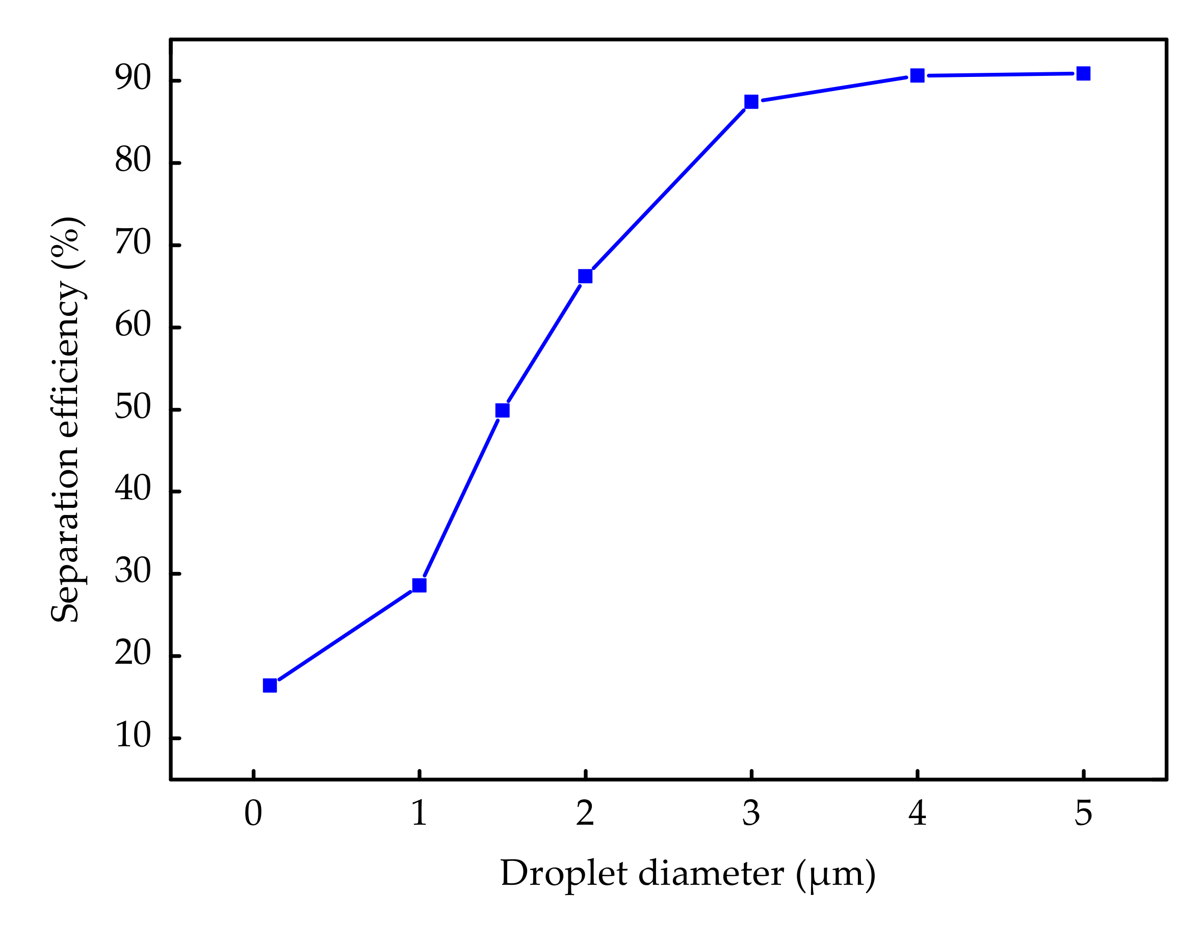
3.3.1. Effects of the Diameter of Droplets on the Separation Efficiency

Wen et al. [37] studied the diameter of droplets in supersonic cyclone separator. The results showed that the diameter of droplets formed by spontaneous condensation of water vapor in the supersonic cyclone separator was between 0.1 and 4 μm. Therefore, the droplet diameter was defined as 0.1–5 μm in this paper, and its influence on the separation effect was studied, as shown in Figure 9. The separation efficiency increased with the droplet diameter increasing from 0.1 μm to 3 μm, which reflected the conclusion in literature [26] that the separation efficiency increased with the increase of droplet diameter under certain swirling conditions. When the droplet diameter was between 0.1 μm and 3 μm, droplets were mainly dominated by the centrifugal force. The larger the diameter and mass of a single droplet, the greater the centrifugal force. Therefore, with the increase of droplet diameter, droplets could easily enter the separator through the annular gap. When the droplet diameter exceeded 3 μm, the droplet diameter had little effect on the separation efficiency. This was because centrifugal force no longer played a major role in controlling droplet motion. When the droplet diameter exceeded 3 μm, the separation efficiency of the separator was about 90%. In order to improve the separation efficiency, it was necessary to increase the droplet diameter to more than 3 μm as much as possible. For increasing droplet diameter, the authors believed that the expansion angle of the Laval nozzle can be reduced, which could not only increase the probability of collision between droplets and facilitate droplets growth, but also reduce the distance of droplets to the wall. In addition, it was possible to add artificial nucleus of condensation, which could contribute to the nucleation rate and droplet number and then increase the diameter of droplets.

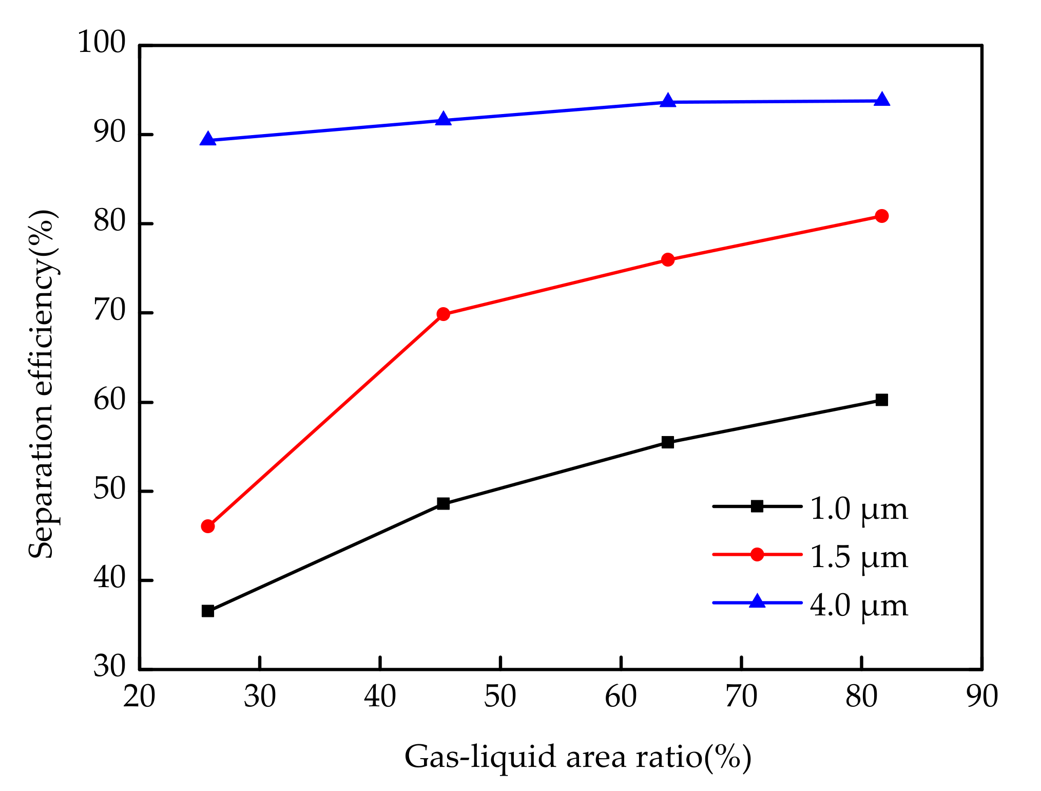
3.3.2. Effect of Gas–Liquid Area Ratio on Separation Efficiency

Due to the effect of centrifugal force, a large number of droplets entered the separator through the annular gap. In order to study the effects between the area of the annular gap and area of the diffuser inlet on the separation efficiency, the gas–liquid area ratio could be defined as:
ε = A l A g × 100 %
where Al is the area of the annular gap, and Ag is the area of the diffuser inlet.
The effect of the gas–liquid area ratio on the separation efficiency of the supersonic cyclone separator was studied under the condition that the inlet area of the diffuser was unchanged and the area of the annulus was changed, as shown in Figure 10.
When the diameter of droplets was 1.0 μm, the separation efficiency of droplets increased with the increase of gas–liquid area ratio. When the gas–liquid area ratio was 25.69%, the separation efficiency of droplets was only 36.56%; when the gas–liquid area ratio was 81.69%, the separation efficiency of droplets was 60.24%. When the diameter of droplets was 1.5 μm, the separation efficiency of droplets increased with the increase of the gas–liquid area ratio. When the gas–liquid area ratio was 81.69%, the separation efficiency of droplets was 80.89%. When the diameter of the droplet was 4 μm, the gas–liquid area ratio had little effect on the separation efficiency of the droplet. Thus, for the same diameter of droplets, when the gas–liquid area ratio increased (that is, annular area increased), the probability of droplets entering the separator increased, so the separation efficiency increased with the increase of the gas–liquid area ratio. When the diameter of droplets was 4 μm, the effect of the gas–liquid area ratio on separation efficiency was much less than that of the centrifugal effect, that is, the separation of droplets was basically completed under centrifugal force, and the effect of the gas–liquid area ratio on separation efficiency could be neglected. Under the same conditions, increasing the gas–liquid ratio, that is, increasing the annulus area, could increase the probability of droplets entering the separator, and the separation efficiency could also be improved. In the design of supersonic cyclone separator, it was necessary to note that the gas–liquid area ratio was small extremely, which was not conducive to the separation of gas and liquid, and the gas–liquid area ratio was too large, which made excessive dry gas into the separator and increased the pressure of the next stage equipment. Based on the above analysis, to improve the separation efficiency, the gas–liquid area ratio of the designed supersonic cyclone separator should be about 45.25%, as much as possible.

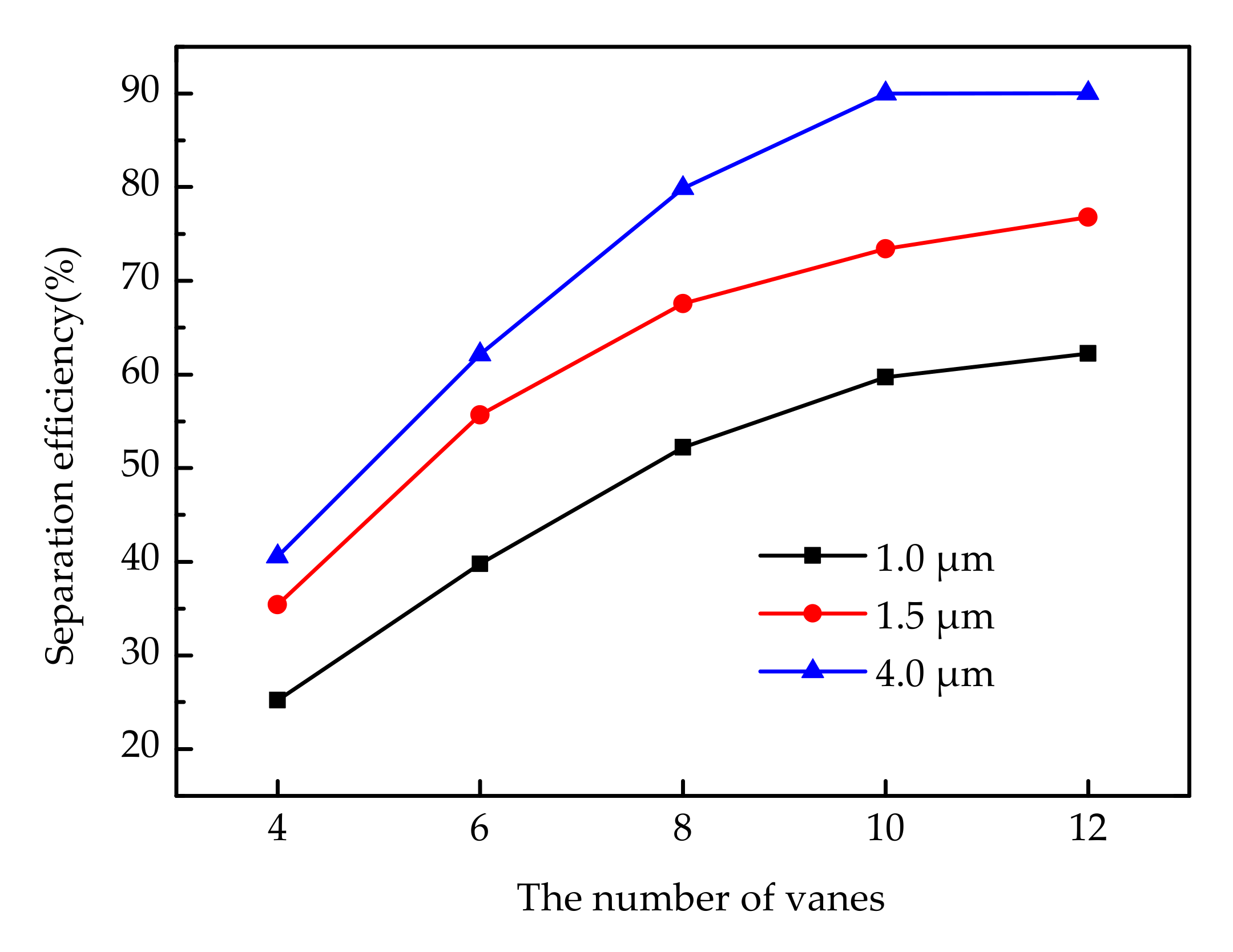
3.3.3. Effects of the Number of Vanes on the Separation Efficiency

The swirling flow of natural gas in the supersonic cyclone separator was an indispensable condition for the effective purification of natural gas. The swirling flow of gas was produced by the swirler, so the structure of the swirler had an important influence on the separation effect. The number of vanes, the outlet angle, the height of vanes and so on are the structures that influence the swirl intensity. In this paper, the number of vanes that had a direct impact on the swirl intensity was selected as the research object.
The effect of the number of vanes on the separation efficiency was analyzed, as shown in Figure 11. For droplets with the diameter of 1 μm, when the number of vanes was four, the separation efficiency of the supersonic cyclone separator was only 25.21%. The separation efficiency increased with the increase of the number of vanes. When the number of vanes reached 12, the separation efficiency reached a maximum value 62.23%. For droplets with the diameter of 4 μm, when the number of vanes was four, the separation efficiency of the supersonic cyclone separator was 40.56%. When the number of vanes reached 10, the separation efficiency reached a maximum value of about 90%. With the increase of the vane number, the width of the fluid channel between vanes decreased, allowing the fluid to get sufficient tangential acceleration, which could improve the separation efficiency of the supersonic cyclone separator. With the increase of the number of vanes, there would be a greater pressure loss. Considering the balance of pressure loss and separation efficiency, the number of vanes of the swirler in this article was set to 10.

4. Conclusions

In this article, a discrete particle model was employed to study the factors affecting the separation efficiency of the supersonic cyclone separator for sustainable development of the natural gas industry. On the basis of an accurate numerical model, the flow field of a supersonic cyclone separator was analyzed, the trajectories of droplets were predicted, and the factors affecting the separation efficiency of droplets were investigated. The Major conclusions can be drawn as follows.
(1)
Laval nozzle and swirler of supersonic cyclone separators were the core components to affect the dewatering efficiency of the device. Laval nozzle could provide the necessary conditions for the condensation of water vapor in the supersonic state, droplets with sufficient centrifugal force were thrown to the wall or into the separator to achieve gas–liquid separation process by the swirler.
(2)
The trajectories of droplets in the supersonic cyclone separator were predicted. Droplets had three typical trajectories affected by centrifugal effect and inertia effect. The existence of a shock wave increases the swirl intensity of droplets, which is conducive to the separation of droplets.
(3)
In order to improve the efficiency of a supersonic cyclone separator and promote the sustainable development of the natural gas industry, the diameter of droplets should be increased as much as possible, the gas–liquid area ratio should be about 45.25%, and the number of vanes should be to 10.

Author Contributions

Conceptualization, Z.D. and Z.M.; methodology, J.Z.; software, S.S. and Y.G.; validation, J.Z.; investigation, Z.M.; resources, Y.G.; data curation, Z.M. and L.L.; writing—original draft preparation, Y.G. and S.S.; writing—review and editing, Z.D.; supervision, J.Z.; project administration, Z.D. All authors have read and agreed to the published version of the manuscript.

Funding

This research was funded by the Shandong Provincial Primary Research & Development Plan of China (Grant No. 2017GGX40113 and Grant No.2019GSF109009), and Shandong Province Taishan Scholar Project and Overseas Taishan Scholar Project.

Conflicts of Interest

The authors declare no conflict of interest.

References

  1. Fu, M.; Yang, Y.; Tian, L.; Zhen, Z. The Spatiotemporal Dynamics of Natural Gas Imports in OECD Countries. Sustainability 2017, 9, 2106. [Google Scholar] [CrossRef] [Green Version]
  2. Wang, B.; Liu, X.J.; Xiong, Z.; Cheng, J.J.; Yang, B.; Yu, C.H. Corrosion reasons and control measures of a natural gas pipeline. Surf. Technol. 2018, 47, 89–94. [Google Scholar] [CrossRef]
  3. Mokhatab, S.; Wilkens, R.J.; Leontaritis, K.J. A review of strategies for solving gas-hydrate problems in subsea pipelines. Energy Sources 2007, 29, 39–45. [Google Scholar] [CrossRef]
  4. Elendu, C.C.; Ude, C.N.; Odoh, E.E.; Ihedioha, O.J. Natural gas dehydration with triethylene glycol (TEG). Eur. Sci. J. 2015, 11, 68–78. [Google Scholar]
  5. Ohlrogge, K.; Brinkmann, T. Natural gas cleanup by means of membranes. Ann. N. Y. Acad. Sci. 2010, 984, 306–317. [Google Scholar] [CrossRef] [PubMed]
  6. Myrlla, G.R.S.S.; Leilane, M.S.C.; José, L.M.; Oféliade, Q.F.A. Natural gas dehydration by molecular sieve in offshore plants: Impact of increasing carbon dioxide content. Energy Convers. Manag. 2017, 149, 760–773. [Google Scholar]
  7. Shang, J. Experimental research on the expansion refrigeration technology for natural gas dehydration and dealkylation. Liaoning Chem. Ind. 2014, 43, 1339–1341. [Google Scholar]
  8. Duan, Z.Y.; Liang, L.H.; Li, S.; Liu, Z.; Li, Z.J.; Liu, X.Z. Natural gas supersonic cyclone separation technology with the integration of condensation and centrifugation. Nat. Gas Ind. 2018, 38, 93–99. [Google Scholar]
  9. Betting, M.; Epsom, H. Supersonic separator gains market acceptance. World Oil 2007, 4, 197–200. [Google Scholar]
  10. Karimi, A.; Abdi, M.A. Selective dehydration of high-pressure natural gas using supersonic nozzles. Chem. Eng. Process. Process Intensif. 2009, 48, 560–568. [Google Scholar] [CrossRef] [Green Version]
  11. Wen, C.; Cao, X.; Yang, Y.; Zhang, J. Evaluation of natural gas dehydration in supersonic swirling separators applying the Discrete Particle Method. Adv. Powder Technol. 2012, 23, 228–233. [Google Scholar] [CrossRef]
  12. Wen, C.; Cao, X.; Yang, Y.; Li, W.L. Numerical simulation of natural gas flows in diffusers for supersonic separators. Energy 2012, 37, 195–200. [Google Scholar] [CrossRef]
  13. Vaziri, B.M.; Shahsavand, A. Analysis of supersonic separators geometry using generalized radial basis function (GRBF) artificial neural networks. J. Nat. Gas Sci. Eng. 2013, 13, 30–41. [Google Scholar] [CrossRef]
  14. Niknam, P.H.; Mortaheb, H.R.; Mokhtarani, B. Optimization of dehydration process to improve stability and efficiency of supersonic separation. J. Nat. Gas Sci. Eng. 2017, 43, 90–95. [Google Scholar] [CrossRef]
  15. Wen, C.; Cao, X.W.; Yang, Y.; Zhang, J. Swirling effects on the performance of supersonic separators for natural gas separation. Chem. Eng. Technol. 2011, 34, 1575–1580. [Google Scholar] [CrossRef]
  16. Wen, C.; Yang, Y.; Walther, J.H.; Pang, K.M.; Feng, Y.Q. Effect of delta wing on the particle flow in a novel gas supersonic separator. Powder Technol. 2016, 304, 261–267. [Google Scholar] [CrossRef]
  17. Ma, Q.F.; Hu, D.P.; He, G.H.; Hu, S.J.; Liu, W.W.; Xu, Q.L.; Wang, Y.X. Performance of inner-core supersonic gas separation device with droplet enlargement method. Chin. J. Chem. Eng. 2009, 17, 925–933. [Google Scholar] [CrossRef]
  18. Hu, D.P.; Wang, Y.G.; Ren, W.W.; Zhao, J.H.; Liu, P.Q. Flow characteristic of supersonic gas separator with diversion cone. CIESC J. 2016, 67, 2417–2425. [Google Scholar]
  19. Hu, D.P.; Wang, Y.G.; Ma, C. Numerical simulation of supersonic separator with axial or tangential outlet in reflow channel. Chem. Eng. Process. Process Intensif. 2018, 124, 109–121. [Google Scholar] [CrossRef]
  20. Bian, J.; Jiang, W.M.; Teng, L.; Liu, Y.; Wang, S.W.; Deng, Z.F. Structure improvements and numerical simulation of supersonic separators. Chem. Eng. Process. Process Intensif. 2016, 110, 214–219. [Google Scholar] [CrossRef]
  21. Cao, X.W.; Yang, W. The dehydration performance evaluation of a new supersonic swirling separator. J. Nat. Gas Sci. Eng. 2015, 27, 1667–1676. [Google Scholar] [CrossRef]
  22. Wen, C.; Cao, X.W.; Wu, L.H. Structure design and numerical simulation of a novel supersonic swirling separator. J. China Univ. Pet. 2010, 34, 119–122. [Google Scholar]
  23. Yang, Y.; Wen, C.; Wang, S.L.; Feng, Y.Q. Theoretical and numerical analysis on pressure recovery of supersonic separators for natural gas dehydration. Appl. Energy 2014, 132, 248–253. [Google Scholar] [CrossRef]
  24. Liu, X.W.; Liu, Z.L. Numerical investigation and improvement strategy of flow characteristics inside supersonic separator. Sep. Sci. Technol. 2017, 53, 940–952. [Google Scholar] [CrossRef]
  25. Eriqitai; Han, J.; Duan, R.; Wu, M. Performance of dual-throat supersonic separation device with porous wall structure. Chin. J. Chem. Eng. 2014, 22, 370–382. [Google Scholar] [CrossRef]
  26. Liu, X.W.; Liu, Z.L.; Li, Y.X. Investigation on separation efficiency in supersonic separator with gas-droplet flow based on DPM approach. Sep. Sci. Technol. 2014, 49, 2603–2612. [Google Scholar] [CrossRef]
  27. Yang, Y.; Wen, C. CFD modeling of particle behavior in supersonic flows with strong swirls for gas separation. Sep. Purif. Technol. 2017, 174, 22–28. [Google Scholar] [CrossRef]
  28. Vaziri, B.M.; Shahsavand, A. Optimal selection of supersonic separators inlet velocity components via maximization of swirl strength and centrifugal acceleration. Sep. Sci. Technol. 2015, 50, 752–759. [Google Scholar] [CrossRef]
  29. Malyshkina, M.M. The procedure for investigation of the efficiency of purification of natural gases in a supersonic separator. High Temp. 2010, 48, 244–250. [Google Scholar] [CrossRef]
  30. Jiang, W.; Bian, M.J.; Wu, A.; Gao, S.; Hou, D.Y. Investigation of supersonic separation mechanism of CO2 in natural gas applying the Discrete Particle Method. Chem. Eng. Process. Process Intensif. 2018, 123, 272–279. [Google Scholar] [CrossRef]
  31. Yang, Y.; Li, A.Q.; Wen, C. Optimization of static vanes in a supersonic separator for gas purification. Fuel Process. Technol. 2017, 156, 265–270. [Google Scholar] [CrossRef]
  32. Wen, C.; Cao, X.W.; Yan, B.; Zhang, J. Optimization design of diffusers for supersonic separators. Appl. Mech. Mater. 2010, 44–47, 1913–1917. [Google Scholar] [CrossRef]
  33. Alobaid, F. A particle-grid method for Euler-Lagrange approach. Powder Technol. 2015, 286, 342–360. [Google Scholar] [CrossRef]
  34. Morsi, S.A.; Alexander, A.J. An investigation of particle trajectories in two-phase flow systems. J. Fluid Mech. 2006, 55, 193–208. [Google Scholar] [CrossRef]
  35. Zhou, C.; Duan, Z.Y.; Zhang, T.; Fan, L.J.; Liu, X.Z.; Liu, Y.Z.; Jia, W.G. Design and numerical optimization of natural gas supersonic dehydration unit swirl parts. Chem. Eng. (China) 2017, 45, 63–67. [Google Scholar] [CrossRef]
  36. Jiang, W.M.; Liu, Z.L.; Liu, X.L.; Li, G.S.; Liu, J.D. Experimental study on wet air in supersonic condensation flows. CIESC J. 2011, 62, 97–102. [Google Scholar]
  37. Wen, C.; Cao, X.W.; Yang, Y. Swirling flow of natural gas in supersonic separators. Chem. Eng. Process. Process Intensif. 2011, 50, 644–649. [Google Scholar] [CrossRef]
Figure 1. The supersonic cyclone separator: (a) schematic diagram; (b) structural parameters diagram of the supersonic cyclone after x = 0.
Sustainability 12 00488 g001
Figure 2. The schematic diagram of the grid. (a) The grids of the supersonic cyclone separator; (b) the grids between the Swirler and the Laval nozzle.
Sustainability 12 00488 g002
Figure 3. Independent verification of grids.
Sustainability 12 00488 g003
Figure 4. The geometric structure of the Laval nozzle.
Sustainability 12 00488 g004
Figure 5. Comparisons of the pressure distribution along the axis of the Laval nozzle.
Sustainability 12 00488 g005
Figure 6. Gas flow field in the supersonic separator. (a) Pressure; (b) Temperature; (c) Velocity; (d) Mach number.
Sustainability 12 00488 g006
Figure 7. The tangential velocity vector map at different sections of the Laval nozzle.
Sustainability 12 00488 g007
Figure 8. Droplet trajectory in supersonic cyclone separator. (a) Droplets reached the wall; (b) Droplets reached the outlet of liquid; (c) Droplet reached the outlet of gas.
Sustainability 12 00488 g008
Figure 9. Effects of droplet diameters on the separation efficiency.
Sustainability 12 00488 g009
Figure 10. Effects of the gas–liquid area ratio on the separation efficiency.
Sustainability 12 00488 g010
Figure 11. Effects of the vane number on the separation efficiency.
Sustainability 12 00488 g011
Table 1. Operating parameters of the Laval nozzle.
Operating ParametersUnitValue
Ambient temperature°C17.8
Ambient humidity%16.2
Inlet pressureMPa0.46
Inlet temperature°C14.9
Inlet relative humidity of air%83
Inlet flow ratem3/h33.8

