Abstract
This study aimed to determine the difference between two alternatives for pre-stressed normal-strength concrete beams according to life-cycle assessments (LCAs): strengthening the PNSC (pre-stressed normal-strength concrete) beam on one side with a 70 mm width, steel-fibered, high-strength concrete layer (Case 1) and strengthening the PNSC beams by jacketing on three sides with 30 mm width, ultra-high-performance, fiber-reinforced concrete layers (Case 2). We conducted LCAs of these cases using the ReCiPe2016 midpoint and endpoint-single-score methods. The differences among the beams’ endpoint-single-score results were evaluated using a two-stage nested analysis of variance. The ReCiPe2016 midpoint results showed that compared to Case 2, Case 1 reduced the global warming potential, terrestrial ecotoxicity, water consumption, and fossil-resource-scarcity impacts by 73–80%. The ReCiPe2016 endpoint-single-score results showed that the environmental damage from Case 1 was significantly lower (p = 0.0003) than that from Case 2. These findings could be promising and useful for studying sustainability in construction.
1. Introduction
In the construction sector, the strengthening of concrete structures is an important issue for both the repair of deteriorated structures and strengthening of normal-strength concrete (NSC) [1]. One of the most common strengthening approaches is using steel-fibered concrete, including steel-fibered high-strength concrete (SFHSC) [2] and ultra-high-performance fiber-reinforced concrete (UHPFRC) [3]. Typically, this steel-fibered concrete is used for additional strengthening layers.
Over the years, researchers have reported that, as a result of steel-fibered concrete-related strengthening, the mechanical properties and durability of composite beams including at least two layers—NSC as a core and SFHSC or UHPFRC as a strengthening layer—have been improved [1]. In this respect, the materials, configurations, and widths of the strengthening layer have been changed from study to study. For example, Al-Osta et al. [1] studied three different strengthening configurations consisting of a 30 mm width UHPFRC layer used in the NSC experimental beams—bottom-side strengthening in the tensile zone, two-longitudinal-side strengthening, and three-side strengthening—and reported increases of about 17%, 46%, and 85% in the load-bearing capacity, respectively. Iskhakov et al. [4] experimentally researched a pre-stressed normal-strength concrete (PNSC) beam strengthened on one side by a 70 mm width SFHSC layer in the compressed zone (PNSC-SFHSC) and reported that the load-bearing capacity of the PNSC-SFHSC was approximately 80% higher than that of the PNSC. Turker and Torun [5] experimentally studied two different strengthening widths for UHPFRC layers, 30 and 50 mm, used in NSC beams in the compressed zone (NSC-UHPFRC) and reported that the load-bearing capacity of the NSC-UHPFRC beams increased by averages of 11% and 22%, respectively, compared to that of the NSC beams.
However, both SFHSC and UHPFRC require larger quantities of cement, approximately 450–752 kg/m3 [6,7], which is more than that required for NSC, at approximately 360 kg/m3 [8]. SFHSC and UHPFRC also use around 40 kg/m3 [9] and 242 kg/m3 [7] of steel fibers, respectively This greater amount of cement and steel fibers can lead to an increased environmental impact. In addition, strengthening layers of different configurations and widths require different amounts of SFHSC and UHPFRC. Therefore, these different strengthening alternatives can lead to various degrees of environmental damage, which cannot be neglected due to the very high CO2 emissions generated from their production [7].
In particular, the production of 1 kg of Portland cement and of 1 kg of steel fibers led to 0.833 and 3.44 kg CO2-eq, respectively, thus increasing the potential impact on global warming [7]. The source of such high CO2 emissions is the high energy consumption during the materials’ production [7,10]. During clinker production, much additional CO2 comes from the calcination of limestone [10]. Thus, to decrease the environmental impacts from these building materials, the construction industry should find a way to produce lower quantities of cement and steel. In this respect, much life-cycle assessment (LCA) research has been focused on studying the possibility of decreasing cement and steel use in the construction sector.
According to ISO 14040 [11], LCA is a total “cradle-to-grave” methodology (the whole life-cycle from raw material acquisition to final disposal is taken into account) that focuses on products as well as services to evaluate all environmental impacts. LCA collects raw material inputs and gases and waste output data associated with the product life-cycle and applies scientific models to convert the output data to environmental impacts and damage. This allows the selection of options with the least environmental damage, thereby decreasing environmental problems such as global warming, ozone depletion, fossil-resource scarcity, and water consumption, among others. LCA, the most comprehensive environmental evaluation methodology today, was thus adopted in the present study.
Habert et al. [12] conducted an LCA of the UHPFRC-based and traditional NSC-based rehabilitation approaches applied to existing bridges. The authors concluded that the UHPFRC-based approach released only 0.1–0.3 times more CO2 than the traditional approach due to the much lower volume of the required UHPFRC compared to that of the required NSC. However, Stengel and Schiessl [7], who performed LCAs of the existing NSC and UHPFRC bridges with the same deck-slab thickness, reported that the UHPFRC bridge involved 1.5–2.4 times more global warming potential, ozone-depletion potential, photo-chemical ozone creation, acidification potential, and eutrophication potential impacts than the NSC bridge. Hajiesmaeili et al. [13] evaluated LCAs of three different bridge-related restorative approaches—(i) complete demolition and new reconstruction, (ii) strengthening with UHPFRC, and (iii) strengthening with ultra-high-performance polyethylene fiber concrete (UHPPFRC)—and reported that the strengthening with UHPPFRC led to a reduction in global warming potential by 55% and 29%, respectively, compared to the complete demolition and new construction, and strengthening with UHPFRC.
Beam-related LCAs were presented by Stengel and Schiessl [7] and Zingg et al. [14]. Stengel and Schiessl [7] evaluated the LCAs of a pre-stressed ultra-high-performance concrete (UHPC) girder beam and a hot-rolled I-beam with similar heights and reported that the production of the former led to 5% and 39% decreases in the global warming and acidification potentials, respectively, compared with that of the latter. Zingg et al. [14] evaluated LCAs of two pre-stressing approaches (steel- and carbon-fiber-reinforced polymer-pre-stressing) applied to a high-strength concrete (HSC) beam, and reported that the HSC beam pre-stressed with carbon-fiber-reinforced polymer led to a decrease (about 50%) in the global warming potential compared to the HSC beam pre-stressed with steel.
We assume that different materials, configurations, and widths for the strengthening layer can lead to different environmental damage. On the other hand, LCAs of strengthening layers in composite beams, which have the greatest potential to reduce environmental impacts, have not yet been studied. Therefore, the aim of this study was to determine the differences in the LCA results for two steel-fibered-concrete strengthening alternatives for the PNSC beam, which have the same load-bearing capacity but extremely different amounts of cement and steel fiber in their strengthening layer. For this, we used two following alternatives: (i) strengthening a PNSC beam with SFHSC on one side with a 70-mm width (Case 1) and (ii) strengthening a PNSC beam with UHPFRC on three sides with a 30-mm width (Case 2). For these two cases, the LCA was conducted based on the beam-related concrete mixtures described by Iskhakov et al. [4] and Al-Osta et al. [1].
The structure of the paper is as follows: Section 2, Materials and Methods, describes the beams’ designs and concrete mixtures alongside the beams’ LCA and statistical evaluation methods; Section 3, Results and Discussion, shows the results for the beams’ environmental impact and damage according to the LCA; and Section 4, Conclusions, focuses on the importance of using environmental assessment in construction.
2. Materials and Methods
2.1. Beam Designs and Concrete Mixtures
In this study, three pre-stressed NSC (PNSC) beams (with a span of 3000 mm and a 150 × 250 mm cross-section), of concrete class C40/50 (according to EN-206-1 [15]) were considered: (i) a PNSC beam (with a span of 3000 mm and a 150 × 250 mm cross-section) (base case); (ii) a PNSC beam strengthened with SFHSC on one side with a 70 mm width in the compressed zone of the beam section (Case 1) (with a span of 3000 mm and a 150 × 320 mm cross-section); and (iii) a PNSC beam strengthened with UHPFRC on three sides with a 30 mm width (Case 2) (with a span of 3000 mm and a 210 × 280 mm cross-section).
According to Iskhakov et al. [4], the base case beam and the PNSC of the Case 1 beam were made of concrete class C40/50 under industrial conditions for pre-stressed concrete-element production. The specimens were compacted by vibration after casting. The pre-stress was transferred to the beams one day after casting, and the specimens were transported to the university laboratory 2 weeks after production. At the second stage of the Case 1 beam’s production, the SFHSC layer was cast under laboratory conditions, from concrete class C90/100 with a steel-fiber ratio of 40 kg/m3, after which it was compacted by vibration. The specimens were kept for 28 days under normal conditions, similar to those at the construction site, and all tested 28 days after casting the SFHSC layer (and 6 weeks after casting the PNSC layer). According to the obtained results [4], the load-bearing capacity of the Case 1 beam was approximately 80% higher than that of the base case beam: and .
An alternative strengthening method using jacketing, made of UHPFRC, was proposed by Al-Osta et al. [1]. The authors reported that three-side jacketing was the most effective approach and achieved a similar increase in load-bearing capacity (about 85%). Therefore, in this study, the Case 2 beam was selected as an additional strengthening alternative for environmental evaluation.
The constructive schemes and concrete mixtures of the base case and Case 1 were based on Iskhakov et al. [4], while the constructive scheme and concrete mixture of Case 2 was based on Al-Osta et al. [1]. Figure 1, Figure 2 and Figure 3 demonstrate the constructive schemes of the base case, Case 1, and Case 2 beams, respectively. Table 1 shows the concrete mixtures of those three analyzed beams.
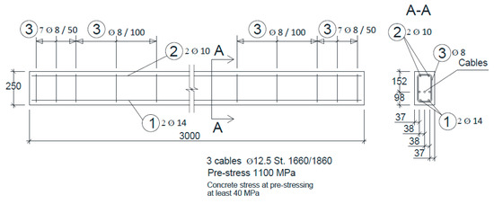
Figure 1.
PNSC (pre-stressed normal-strength concrete) beam (base case) scheme (following Iskhakov et al. [4]).
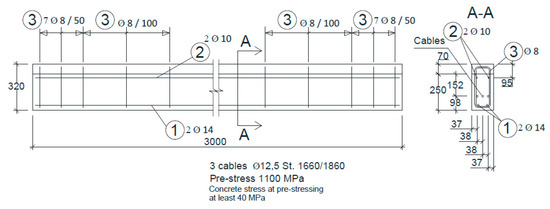
Figure 2.
PNSC beam strengthened with SFHSC (steel-fibered high-strength concrete) on one side with a 70 mm width in the compressed zone of the beam section (Case 1) scheme (following Iskhakov et al. [4]).
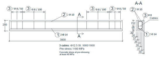
Figure 3.
PNSC beam strengthened with UHPFRC (ultra-high-performance fiber-reinforced concrete) on three sides with a 30 mm width (Case 2) scheme (based on Al-Osta et al. [1]).

Table 1.
Materials required for the production of the following beams: base case, Case 1, and Case 2.
2.2. Life-Cycle Assessment and Statistical Evaluations
According to ISO 13315-1 [16], a “cradle-to-grave” LCA of concrete elements includes the following stages: (i) design, (ii) production/execution, (iii) usage, and (iv) end-of-life. However, we considered that two strengthened PNSC beams (Case 1 and Case 2) would have similar usage stages because they have similar load-bearing capacities. The end-of-life stage strongly depends on the disposal practices and involves much less environmental damage than the production/execution stage [17]. Therefore, we evaluated the production stage only, i.e., performed a “cradle-to-gate” LCA study.
For conducting an LCA, the initial important step is selection of a proper functional unit (FU). ISO 14040 [11] states that “The primary purpose of FU is to provide a reference to which the inputs and outputs are related.” Thus, the FU was “a beam-related strengthening alternative that can provide the increased loading-bearing capacity of the PNSC beam—about 85%.” This FU allowed the comparison of two strengthening alternatives: strengthening a PNSC beam with SFHSC (Case 1) and strengthening a PNSC beam with UHPFRC (Case 2). As previously mentioned, these two strengthening alternatives resulted in similar load-bearing capacities, about 85% greater than the load-bearing capacity of an ordinary PNSC beam (base case).
Using this FU, we conducted the environmental evaluations in four steps. In the first step, after the calculation of the energy required for pre-stressing the beams (Appendix A), we performed the life-cycle inventory (LCI) of the production stage of these three beams (base case, Case 1, and Case 2) (Figure 4). In the second step, we subtracted the environmental damage related to the production of the base case from that related to the production of Cases 1 and 2, respectively. This resulted in the environmental evaluation of only the strengthened layers of the Case 1 and 2 beams. Thereby, in the further steps of the analysis, we worked only with the strengthened layers of Cases 1 and 2. However, for simplicity, we continue to denote these strengthening alternatives “Case 1” and “Case 2”. In the third step, we converted the LCIs of the strengthened layers, only of Cases 1 and 2, into life-cycle impact assessments (LCIAs). In the fourth step, we compared the LCIA results between the strengthened layers, only of Cases 1 and 2, using a two-stage nested mixed analysis-of-variance (ANOVA) model.
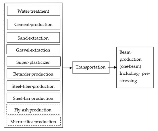
Figure 4.
The first step of the environmental evaluations: life-cycle assessment (LCA) boundary illustrating production of the base case, Case 1, and Case 2 beams (plain line—included processes; dashed line—nonincluded processes).
2.2.1. The First Step
We used the EcoInvent v3.2 database [18] to model the LCIs of the production of the base case, Case 1, and Case 2 beam components—including the water, cement, sand, gravel, super-plasticizer, retarder, steel fibers, and steel bars—as well as to model the pre-stress energy that was transferred to the beams (Table 2). We used the local distances from the producer/supplier to the base case, Case 1, and Case 2 beam-casting place (the laboratory in Leipzig University of Applied Sciences, Leipzig, Germany) to model the transportation of the beams’ components (Table 3). The data from the EcoInvent v3.2 database [18] (Table 2) were used due to the absence of local German data. An analysis of such secondary data was considered appropriate due to the aim of this study, i.e., to compare different PNSC beam-related strengthening alternatives with the same components (cement, water, aggregates, steel fibers, retarder, and super-plasticizer).
Table 2.
The first step of the environmental evaluations: references from the EcoInvent v3.2 database [18] for modeling the life-cycle inventory (LCI) for the base case, Case 1, and Case 2.
Table 3.
The first step of the environmental evaluations: transportation distances from the producer/supplier to the beam-casting place.
According to the EcoInvent v3.2 database [18], the water production included infrastructure and energy use for water treatment and transportation to the end user. The cement production considered the manufacturing processes, mixing, grinding, internal transport, and infrastructure. The sand and gravel production involved the digging process, internal transport, and infrastructure. The steel bar and fiber production comprised the coal, iron and ore extraction and scrap processing; coke making; sinter; a blast furnace; a basic oxygen furnace; an electric-arc furnace; and a rolling mill. The truck was powered by a diesel engine and was involved in the entire fuel supply chain from the exploration and production of crude oil to transportation to the consumer. Thus, the production of the beams and the components’ transportation to the casting site resulted in the LCIs presented in Table 4.
Table 4.
The first step of the environmental evaluations: life-cycle inventory (LCI) for the evaluation of the base case, Case 1, and Case 2 (EcoInvent v3.2 database [18]).
2.2.2. The Second Step
As previously mentioned, for the evaluation of the strengthening layers only, we subtracted the LCIA related to the production of the base case from the LCIAs related to the production of Cases 1 and 2, respectively. Thereby, as previously mentioned, we worked with the strengthened layers only of Cases 1 and 2 in the third and fourth steps of the analysis. However, for simplicity, we continue to denote these strengthening alternatives as “Case 1” and “Case 2”.
2.2.3. The Third Step
The LCIs of Cases 1 and 2 were converted into the LCIAs using the ReCiPe2016 method [18], which allows the consideration of the uncertainty in environmental evaluations through the application of three perspectives (views on environmental problems), including individualist (I), egalitarian (E), and hierarchist (H). These perspectives were adopted from cultural theory [19]. The individualist perspective considers all of the short-term damaging effects. The egalitarian perspective evaluates all of the possible long-term damaging effects. The hierarchist perspective estimates the balance between the short- and long-term damaging effects [20].
For the evaluation of these perspectives, both a midpoint and an endpoint-single-score method were allowable in ReCiPe2016 [18]. The midpoint method assessed 22 environmental impacts, such as the global warming potential, terrestrial ecotoxicity, fossil-resource scarcity, and water consumption, among others. The endpoint-single-score method first converts these environmental impacts into damage to human health, ecosystem quality, and resources. By applying average- and particular-weighting sets to these damages, a single-score evaluation can then be obtained. The average-weighting set contains the individualist/average (I/A), hierarchist/average (H/A), and egalitarian/average (E/A) methodological options, and the particular-weighting set contains the individualist/individualist (I/I), hierarchist/hierarchist (H/H), and egalitarian/egalitarian (E/E) methodological options.
The midpoint and endpoint-single-score methods have different advantages and disadvantages. Using the midpoint method brings less uncertainty in environmental evaluations, whereas the interpretation of 22 environmental impacts is not so easy. Using the endpoint method brings high uncertainty in environmental evaluations, whereas the interpretation of the three environmental damage types offered as an endpoint-single-score is less difficult [20].
Therefore, we applied both midpoint and endpoint-single-score methods to convert the LCIs of Cases 1 and 2 into LCIAs. We analyzed the four most significant environmental impacts (global warming potential, terrestrial ecotoxicity, fossil-resource scarcity, and water consumption) of the beams with the midpoint H method [21]. All six methodological options (I/A, H/A, E/A, I/I, H/H, and E/E) were evaluated with the endpoint-single-score method.
2.2.4. The Fourth Step
We used a two-stage nested mixed ANOVA model because the ReCiPe2016 endpoint-single-score results have a two-stage nested (hierarchical) design structure. This two-stage nested ANOVA model used the following statistical terminology: “sampling frame”, “primary sampling unit”, “subunits”, and “individual subunits”. The sampling frame is the collection of primary sampling units that belong to the same sample—a primary sampling unit consists of two or more subunits, and a subunit contains two or more individual subunits. Measurements were performed on individual subunits [22].
Figure 5 displays two primary sampling units for the application of the ReCiPe2016 endpoint-single-score design structure, which compares the LCIAs of Cases 1 and 2. The primary sampling unit contained two subunits—namely, the average- and particular-weighting sets—and each subunit contained three individual subunits. Two subunits contained six individual subunits, namely, the I/A, H/A, E/A, I/I, H/H, and E/E methodological options of the ReCiPe method. The measurements were performed according to the six methodological options (i.e., six individual subunits), and two beam-related strengthening alternatives were compared by applying these six options simultaneously. Pushkar [21,23] recently used this design structure to evaluate the environmental performance of the substitution of natural materials with industrial byproducts in concretes and green roofs, respectively.
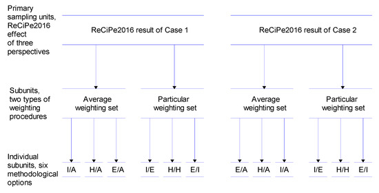
Figure 5.
A two-stage analysis of variance (ANOVA) hierarchical design structure applied to the environmental evaluation of Cases 1 and 2. I/A—individualist/average; H/A—hierarchist/average; E/A—egalitarian/average; I/I—individualist/individualist; H/H—hierarchist/hierarchist; and E/E—egalitarian/egalitarian (the methodological options of the ReCiPe2016 single-score results).
The ReCiPe2016 endpoint-single-score results were multiplied by 103 and log10-transformed prior to statistical analysis. We compared the ReCiPe2016 endpoint-single-score results pairwise using a two-stage nested mixed ANOVA [22]. We used neo-Fisherian significance assessments to evaluate the statistical difference between two ReCiPe2016 endpoint-single-score results [21,23]. The neo-Fisherian paradigm (1) does not fix α, (2) does not describe p-values as “significant” or “nonsignificant”, (3) does not accept null hypotheses based on high p-values but only suspends judgment, (4) interprets significance tests according to “three-valued logic”, and (5) presents effect-size information if necessary [24]. Following Hurlbert and Lombardi [24], the p-values were evaluated according to three-valued logic: it seems to be positive (i.e., there appears to be an environmental-damage difference), it seems to be negative (i.e., there does not appear to be an environmental-damage difference), and judgment is suspended regarding the environmental-damage difference.
3. Results and Discussion
3.1. The ReCiPe2016 Midpoint Results
Figure 6 shows that all four environmental impacts—global warming potential, terrestrial ecotoxicity, water consumption, and fossil-resource scarcity—of Case 1 were much lower than those of Case 2. In particular, compared to the Case 2 impacts, those four Case 1-related impacts were decreased by 78%, 80%, 73%, and 78%, respectively.
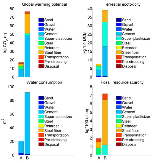
Figure 6.
The environmental impacts of two PNSC-beam-related strengthening alternatives, Cases 1 (A) and 2 (B), evaluated with the ReCiPe2016 midpoint method.
The abovementioned means that compared to Case 2, Case 1 decreased, by 1.3 times, the concrete quantity needed for the strengthening of the PNSC beam with SFHSC on one side with a 70 mm width, and applied the low steel-fiber ratio of 40 kg/m3 [4] in the SFHSC layer versus the 157 kg/m3 used in the UHPFRC layer [1]. In particular, this low steel-fiber ratio of 40 kg/m3 led to 1.5% of the total Case 1-related global warming potential related to the production of steel fibers. In this respect, Abdulkareem et al. [25], who also used a similar amount of steel fibers (38.64 kg/m3) for steel-fibered high-strength concrete (without reinforcing steel bars), reported a somewhat higher percentage, 17%, of total global warming potential stemming from steel-fiber production. Such a difference is due to the different concrete designs, with reinforcing steel bars applied in the present study but not in that by Abdulkareem et al. [25].
Global warming potential and terrestrial ecotoxicity are among the five main and most-influenced impacts related to cement production: global warming potential, terrestrial ecotoxicity, photochemical oxidation potential, acidification potential, and eutrophication potential [26]. Thus, according to other researchers, relative to the total environmental impacts/damage associated with normal-strength concrete, the share for cement was 74–93% [27,28,29].
This abovementioned is because cement production is a highly energy-intensive process and, therefore, releases much CO2 due to energy production with fossil fuels, such as coal, oil, and gas, and the cement-calcination process is an additional major source of CO2 [10]. The reinforcement steel and steel fibers also greatly influenced the global warming potential, with 2.32 and 2.31 kg of CO2 per 1 kg of steel bars and steel fibers, respectively (Table 4).
A similar effect of reinforcement steel and steel fibers was also noticed for fossil-resource scarcity due to the extraction of iron ore for the production of this component (Figure 6). In particular, the fossil-resource scarcity related to the production of the 1.26 kg of steel fibers designed for Case 1 was much lower than that stemming from the production of the 10.03 kg of steel fibers designed for Case 2. Thus, Case 1 was also more attractive than Case 2 in this regard.
Super-plasticizers have a large influence on terrestrial ecotoxicity, at 5.53 kg of 1,4-DCB per 1 kg of super-plasticizer (Table 4). Cement also has a significant influence, at 0.251 kg of 1,4-DCB per 1 kg of cement (Table 4). Thus, the 2.8-times-greater super-plasticizer and 1.9-times-greater cement quantities needed for the jacketing of the PNSC beam with UHPFRC on three sides with a 30 mm width were the main factors making Case 2 environmentally less attractive than Case 1 when evaluating the terrestrial ecotoxicity impact.
Cement also has a large influence on the water consumption impact, with 0.565 m3 of water required per 1 kg of cement (Table 4) for the mixing and grinding of limestone and aluminosilicate materials such as clay for clinker production [18]. In this respect, it was observed early on that more cement was used in Case 2 than in Case 1, making the former less environmentally attractive than the latter regarding this specific impact.
3.2. The ReCiPe2016 Endpoint-Single-Score Results
Figure 7 shows that compared to Case 2, Case 1 led to lower environmental damage. This difference held for all six methodological options; according to the six options evaluated simultaneously, the difference between Cases 1 and 2 was found to be positive (p = 0.0003). This confirmed the preferability of Case 1 as a less-damaging strengthening alternative, as revealed by the ReCiPe2016 midpoint results (Figure 6). In addition, the ReCiPe2016 endpoint-single-score results present evidence that Case 1′s environmental preferability was found to be independent of the applied perspective with regard to different views on the significance of the environmental problem.
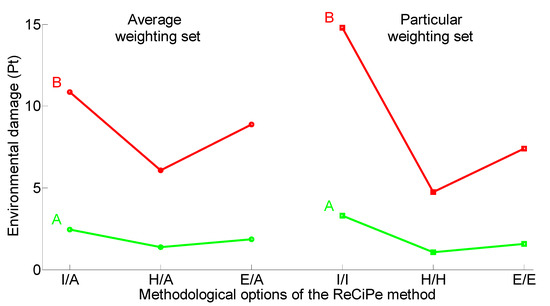
Figure 7.
The environmental damage from two PNSC-beam-related strengthening alternatives, Cases 1 (A) and 2 (B), evaluated using the ReCiPe2016 endpoint-single-score method.
4. Conclusions
In this study, we conducted environmental evaluations of the following two PNSC-beam-related strengthening alternatives: (i) the strengthening of the PNSC beam on one side with an SFHSC layer (Case 1), and (ii) the strengthening of the PNSC beam by jacketing on three sides with UHPFRC layers (Case 2). Based on the results presented by Iskhakov et al. [4] and Al-Osta et al. [1], Cases 1 and 2 provided similar increases in the load-bearing capacity of the strengthened PNSC beams (about 85%). However, the environmental benefits of these two cases of PNSC-beam-related strengthening alternatives were not the same. Specifically, the following results were obtained.
According to the hierarchist (H) methodological option of the ReCiPe2016 midpoint results, the replacement of Case 2 with Case 1 strongly decreased the global warming potential, terrestrial ecotoxicity, water consumption, and fossil-resource-scarcity impacts, by about 73–80%. This is because of the decreased cement quantity and low steel-fiber ratio used in the SFHSC strengthening layer compared to in the UHPFRC strengthening layer. This evidence of the environmental preferability of the Case 1 PNSC-beam-related strengthening alternative was also confirmed by the ReCiPe2016 endpoint-single-score results. We found that the environmental damage caused by production of Case 1 was significantly lower than that for Case 2. In addition, this result was found to be consentient among three different interpretations (egalitarian, individualist, and hierarchist) of the significance of the environmental problem.
We found a significant difference between the studied PNSC-beam-related strengthening alternatives. As the construction industry uses many other configurations and widths for NSC- and PNSC-beam-related strengthening alternatives, seeking to improve mechanical properties and durability, the environmental performance of the applied alternatives should not be neglected.
Author Contributions
Conceptualization, Y.R. and S.P.; data curation, Y.R.; methodology, Y.R. and S.P.; formal analysis, S.P.; writing—original draft preparation, S.P.; writing—review and editing, S.P. and Y.R. All authors have read and agreed to the published version of the manuscript.
Funding
This research received no external funding.
Acknowledgments
The authors are grateful to the five anonymous reviewers for their helpful comments.
Conflicts of Interest
The authors declare no conflict of interest.
Appendix A
Energy Required for Pre-Stressing the Beams
External forces, acting on elastic body and yielding deformations, produce work at appropriate displacements. As a result, the potential energy of deformations occurs in an elastic body. In the case when a tensile force P acts on a rod made of homogeneous material (Figure A1), longitudinal displacement ∆l occurs.

Figure A1.
Tensile deformations of a homogeneous rod.
According to Hooke’s law, normal stresses σ in the cross-section are directly proportional to the strains, ε:
where E is the material modulus elasticity.
The normal stresses are equal to the ratio of the acting force P to the rod’s cross-sectional area, A:
The strains are equal to the ratio of the displacement ∆l to the original rod’s length, l:
Thus, the rod’s displacement could be found as follows:
The work, required for rod extension by a force P, is equal to the area of the triangle 0AB (Figure A2) under the displacement graph:

Figure A2.
Force-displacement relationship.
In our case, the data on the pre-stressed cables is presented in Table A1.
Table A1.
Data on pre-stressed cables.
Table A1.
Data on pre-stressed cables.
| Cable Length , m | Cable Diameter , mm | Pre-Stressing Stress , MPa | Modulus of Elasticity, , MPa |
|---|---|---|---|
| 3 | 12.5 | 1100 | 195,000 |
Therefore, the cable elongation is:
The acting pre-stressing force is:
Finally, the energy, required for pre-stressing the cables per one beam (for three cables) was equal for each of the three investigated cases:
References
- Al-Osta, M.A.; Isa, M.N.; Baluch, M.H.; Rahman, M.K. Flexural behavior of reinforced concrete beams strengthened with ultra-high performance fiber reinforced concrete. Constr. Build. Mater. 2017, 134, 279–296. [Google Scholar] [CrossRef]
- Iskhakov, I.; Ribakov, Y. A design method for two-layer beams consisting of normal and fibered high strength concrete. Mater. Des. 2007, 28, 1672–1677. [Google Scholar] [CrossRef]
- Rahman, S.; Molyneaux, T.; Patnaikuni, I. Ultra high performance concrete: Recent applications and research. Aust. J. Civ. Eng. 2005, 2, 13–20. [Google Scholar] [CrossRef]
- Iskhakov, I.; Ribakov, Y.; Holschemacher, K.; Kaeseberg, S. Experimental investigation and comparison of prestressed single-layer and repaired two-layer reinforced concrete beams. Struct. Concr. 2020. [Google Scholar] [CrossRef]
- Turker, K.; Torun, I.B. Flexural performance of highly reinforced composite beams with ultra-high performance fiber reinforced concrete layer. Eng. Struct. 2020, 219, 110722. [Google Scholar] [CrossRef]
- Bilim, C.; Atis, C.D.; Tanyildizi, H.; Karahan, O. Predicting the compressive strength of ground granulated blast furnace slag concrete using artificial neural network. Adv. Eng. Softw. 2009, 40, 334–340. [Google Scholar] [CrossRef]
- Stengel, T.; Schiessl, P. Life cycle assessment (LCA) of ultra high performance concrete (UHPC) structures. In Eco-Efficient Construction and Building Materials; Woodhead Publishing: Cambridge, UK, 2014; Volume 22, pp. 528–564. ISBN 978-0-85709-045-4. [Google Scholar]
- Al-Mashhadani, M.M.; Canpolat, O.; Aygormez, Y.; Uysal, M.; Erdem, S. Mechanical and microstructural characterization of fiber reinforced fly ash based geopolymer composites. Constr. Build. Mater. 2018, 167, 505–513. [Google Scholar] [CrossRef]
- Iskhakov, I.; Ribakov, Y.; Holschemacher, K.; Mueller, T. Experimental Investigation of Full Scale Two-Layer Reinforced Concrete Beams. Mech. Adv. Mater. Struct. 2014, 21, 273–283. [Google Scholar] [CrossRef]
- Van den Heede, P.; De Belie, N. Environmental impact and life cycle assessment (LCA) of traditional and ‘green’ concretes: Literature review and theoretical calculations. Cem. Concr. Compos. 2012, 34, 431–442. [Google Scholar] [CrossRef]
- ISO 14040 (International Organization for Standardization). Environmental Management Life Cycle Assessment Principles and Framework; International Organization for Standardization: Geneva, Switzerland, 2006. [Google Scholar]
- Habert, G.; Denarie, E.; Sajna, A.; Rossi, P. Lowering the global warming impact of bridge rehabilitations by using Ultra High Performance Fibre Reinforced Concretes. Cem. Concr. Compos. 2013, 38, 1–11. [Google Scholar] [CrossRef]
- Hajiesmaeili, A.; Pittau, F.; Denarie, E.; Habert, G. Life Cycle Analysis of Strengthening Existing RC Structures with R-PE-UHPFRC. Sustainability 2019, 11, 6923. [Google Scholar] [CrossRef]
- Zingg, S.; Habert, G.; Lämmlein, T.; Lura, P.; Denarié, E.; Hajiesmaeili, A. Environmental Assessment of Radical Innovation in Concrete Structures. In Proceedings of the 2016 Sustainable Built Environment (SBE) Regional Conference, Zürich, Switzerland, 15–17 June 2016; pp. 682–687. [Google Scholar]
- Comité Européen de Normalisation (CEN) EN 206-1, Concrete—Part 1: Specification, Performance, Production and Conformity. 2000. Available online: https://infostore.saiglobal.com/preview/98701310834.pdf?sku=869760_SAIG_NSAI_NSAI_2068246 (accessed on 10 May 2020).
- ISO 13315-1 (International Organization for Standardization). Environmental Management for Concrete and Concrete Structures 2012, Part. 1: General Principles; International Organization for Standardization: Geneva, Switzerland, 2012. [Google Scholar]
- Napolano, L.; Menna, C.; Asprone, D.; Prota, A.; Manfredi, G. Life cycle environmental impact of different replacement options for a typical old flat roof. Int. J. Life Cycle Assess. 2015, 20, 694–708. [Google Scholar]
- PRé Consultants. SimaPro; Version 9.0. 0.35; PRé Consultants: Amersfoort, The Netherlands, 2019. [Google Scholar]
- Thompson, M.; Ellis, R.; Wildavsky, A. Political cultures. In Cultural Theory; Westview Press: Boulder, CO, USA, 1990. [Google Scholar]
- Huijbregts, M.A.J.; Steinmann, Z.J.N.; Elshout, P.M.F.; Stam, G.; Verones, F.; Vieira, M.; Zijp, M.; Hollander, A.; van Zelm, R. ReCiPe2016: A harmonised life cycle impact assessment method at midpoint and endpoint level. Int. J. Life Cycle Assess. 2017, 22, 138–147. [Google Scholar]
- Pushkar, S. The Effect of Different Concrete Designs on the Life-Cycle Assessment of the Environmental Impacts of Concretes Containing Furnace Bottom-Ash Instead of Sand. Sustainability 2019, 11, 4083. [Google Scholar] [CrossRef]
- Picquelle, S.J.; Mier, K.L. A practical guide to statistical methods for comparing means from two-stage sampling. Fish. Res. 2011, 107, 1–13. [Google Scholar]
- Pushkar, S. Modeling the substitution of natural materials with industrial byproducts in green roofs using life cycle assessments. J. Clean. Prod. 2019, 227, 652–661. [Google Scholar] [CrossRef]
- Hurlbert, S.H.; Lombardi, C.M. Final collapse of the Neyman-Pearson decision theoretic framework and rise of the neoFisherian. Ann. Zool. Fenn. 2009, 46, 311–349. [Google Scholar] [CrossRef]
- Abdulkareem, M.; Havukainen, J.; Horttanainen, M. How environmentally sustainable are fibre reinforced alkali-activated concretes? J. Clean. Prod. 2019, 236, 117601. [Google Scholar] [CrossRef]
- Chen, C.; Habert, G.; Bouzidi, Y.; Jullien, A. Environmental impact of cement production: Detail of the different processes and cement plant variability evaluation. J. Clean. Prod. 2010, 18, 478–485. [Google Scholar] [CrossRef]
- O’Brien, K.R.; Ménaché, J.; O’Moore, L.M. Impact of fly ash content and fly ash transportation distance on embodied greenhouse gas emissions and water consumption in concrete. Int. J. Life Cycle Assess. 2009, 14, 621–629. [Google Scholar] [CrossRef]
- Celik, K.; Meral, C.; Gursel, A.P.; Mehta, P.K.; Horvath, A.; Monteiro, P.J.M. Mechanical properties, durability, and life-cycle assessment of self-consolidating concrete mixtures made with blended Portland cements containing fly ash and limestone powder. Cem. Concr. Compos. 2015, 56, 59–72. [Google Scholar] [CrossRef]
- Gursel, A.P.; Ostertag, C.P. Impact of Singapore’s importers on life-cycle assessment of concrete. J. Clean. Prod. 2016, 118, 140–150. [Google Scholar] [CrossRef]
© 2020 by the authors. Licensee MDPI, Basel, Switzerland. This article is an open access article distributed under the terms and conditions of the Creative Commons Attribution (CC BY) license (http://creativecommons.org/licenses/by/4.0/).