Article

A Power Flow Control Strategy for Hybrid Control Architecture of DC Microgrid under Unreliable Grid Connection Considering Electricity Price Constraint

by
Faris Adnan Padhilah
and
Kyeong-Hwa Kim
*
Department of Electrical and Information Engineering, Research Center for Electrical and Information Technology, Seoul National University of Science and Technology, Seoul 01811, Korea
*
Author to whom correspondence should be addressed.
Sustainability 2020, 12(18), 7628; https://doi.org/10.3390/su12187628
Submission received: 17 August 2020 / Revised: 10 September 2020 / Accepted: 15 September 2020 / Published: 16 September 2020
(This article belongs to the Collection Microgrids: The Path to Sustainability)

Abstract

:
This paper presents a power flow control strategy for a hybrid control architecture of the DC microgrid (DCMG) system under an unreliable grid connection considering the constraint of electricity price. To overcome the limitation of the existing schemes, a hybrid control architecture which combines the centralized control and distributed control is applied to control DCMG. By using the hybrid control approach, a more optimal and reliable DCMG system can be constructed even though a fault occurs in the grid or a central controller (CC). The power flow control strategy for the hybrid DCMG control architecture also takes the constraint of electricity price into account for the purpose of minimizing the electricity cost. In the proposed hybrid control, the high bandwidth communication (HBC) link is used in the centralized control to connect the CC with DCMG power agents. On the other hand, the low bandwidth communication (LBC) link is employed to constitute the distributed control. A small size of data is used to exchange the information fast between the agents and CC, or between each agent and its neighbors, which increases the reliability and robustness of the DCMG system in case of a fault in the communication link of the centralized control. A DCMG system with 400-V rated DC-link voltage which consists of a wind power agent, a battery agent, a grid agent, a load agent, and a CC is constructed in this study by using three power converters based on 32-bit floating point digital signal processor (DSP) TMS320F28335 controller. Various simulation and experimental results prove that the proposed scheme improves the system stability and robustness even in the presence of a fault in the communication link of the centralized control. In addition, the proposed scheme is capable of maintaining the DC-link voltage stably at the nominal value without severe transients both in the centralized control and distributed control, as well as both in the grid-connected case and islanded case. Finally, the scalability of the DCMG system is tested by adding and removing additional wind power agent and battery agent during a certain period.

1. Introduction

Environmental concern and economic factors make microgrid (MG) research more intense lately. In general, an MG is a small power system which integrates loads, sources, and storage devices in an electric network by connecting them through power electronic converters [1]. MGs are supplemented by the distributed generation (DG) power from renewable energy sources such as photovoltaic (PV), wind turbine, and hydroelectric. The output from renewable energy sources often fluctuates from time to time as the renewable energy is highly dependent on natural conditions. To overcome this power fluctuation, an energy storage system (ESS) is usually added into the MG system [2]. In addition to the ESS, technology developments also make it possible to connect many power sources into MG. In [3], a supercapacitor is employed to alleviate the voltage transient during load changes. The research in [2] considers an electric vehicle with PV and ESS in a coordinated control to suppress the system frequency fluctuation in an MG system.
Depending on the bus voltage type, MGs can be classified as DC microgrids (DCMGs) and AC microgrids (ACMGs). Between them, recent interest is focused on DCMG because of its attractive feature [4]. DCMGs have several advantages over ACMGs since some constraints in ACMGs such as transformer inrush current, reactive power flow, frequency synchronization, current harmonics, and power quality can be avoided in DCMG systems [5]. Furthermore, as most DGs generate DC power or are inevitably converted to DC first, the integration process is much easier in the DCMG system, which leads to a construction of a more efficient MG system [6,7]. DCMG can also reduce the power conversion loss in the consumer sector because new electronic loads are dominated by DC loads [8]. Moreover, several AC loads like induction motors can be supplied by DCMGs using inverter-fed drive systems [9].
In order to guarantee that the MG system works effectively and efficiently, a coordination of power agents such as DGs, ESSs, and grid is needed in MG. Coordinated control of MG can be classified into three categories based on the MG architecture: the distributed control, decentralized control, and centralized control. In the distributed control approach, all the agents communicate with their respective neighbors and the operating conditions are decided based on the internal information of the agent and the external information of other agents. In the decentralized control scheme, all the agents determine their operating conditions by using only the internal information of the agent without any information from other agents. Meanwhile, in the centralized control method, all the agents send data to a central controller (CC), and then, CC decides the operating conditions of all the agents based on the acquired data.
All the coordination control architectures have their own advantages and disadvantages. By integrating the energy management system (EMS) to CC in the centralized control, it is possible to reach a global optimum solution while satisfying some constraints at the same time [10]. The centralized control approach also increases MG stability [11] and optimizes the power exchange [12] as well as the economic dispatch of DG units with high accuracy and controllability [13]. In spite of these advantages, there exist several disadvantages in the centralized control architecture. It is difficult to integrate many power units in this scheme. As the number of power units is increased, the computational burden of the CC is also increased [14]. The communication link between the CC and DG agents also becomes more fragile to communication failure [15]. Moreover, the centralized control mode is faced with a single point of failure issue because it highly relies on the CC to control the entire system of MG. In the centralized control, a fault detection delay caused by the fault in the communication link creates another problem in the MG system. With the aim of improving the system reliability of MG, the research in [16] proposes to install the local emergency mode in each DCMG agent in the centralized control architecture. In this local emergency mode, each agent determines its operating mode instead of the CC. However, this approach still has the limitations of the centralized control.
As for the decentralized control approach, the number of the power agents can be increased or decreased easily in the MG system. However, this scheme is lack of coordination to achieve an optimum solution [17] because the communication link does not exist.
On the other hand, the power units can be easily added or removed in the distributed control approach. This scheme has more robustness in terms of the communication link than the centralized control architecture. In addition, the existence of the communication links makes the MG system more probable to reach an optimum solution. In [18], an improved power management strategy is presented for multi-agent system (MAS)-based distributed control of DCMG. In this scheme, the DC-link voltage restoration algorithm is also developed to ensure the system power balance even under communication network problems. However, it is well known that the distributed control achieves only a sub-optimum solution since the objective of the distributed control is only to improve the reliability of MG [10]. Moreover, it is difficult to anticipate all the operating scenarios in a large MG system with many DGs [10].
To overcome such a limitation in each coordination control, a hybrid control architecture that combines two or more coordination control methods is introduced. The study in [19] proposes a hybrid control architecture to combine the centralized and distributed architectures for an islanded DCMG. In this work, the distributed control is used only as a backup plan when a fault occurs in the CC. However, excessive generated power from the DG units is not effectively utilized in this scheme when the DCMG operates in the distributed control mode. In addition to that, the DCMG system experiences a moderate transient period in the transition between the distributed control and centralized control. A combination of the centralized and decentralized architectures in a hierarchical control strategy is also presented in [20]. This study allows a robust and seamless transfer between the grid-connected and islanded cases in the ACMG operation.
The electricity generation by DG units and power flow control strategy mainly determine the power injected into or absorbed from the main grid. The power from the grid affects the electricity price which consumers should pay. The time-of-use pricing (TOU), real-time pricing (RTP), and stepwise power tariff (SPT) methods have been used to determine electricity bills worldwide [21]. The TOU and RTP tariffs have been used in optimal battery sizing in smart home systems [22,23]. The TOU pricing divides daily electricity bills into three different levels such as on-peak rate, mid-peak rate, and off-peak rate [22]. The TOU policy has been adopted in Ontario, Canada to calculate the electricity bill for in-home energy management systems which use the wind turbine and battery energy storage system (BESS) [24]. The RTP method has been implemented in the U.S. and Australia for years [25]. Compared to the TOU, the RTP method that depends on the real market cost of delivering electricity offers a higher variability of electricity bill [26]. The SPT policy divides monthly electricity bills based on consumer electricity consumption. In this method, higher electricity consumption leads to higher electricity price [27]. China is one of the countries to use the SPT method to determine electricity bills [28].
Considering the limitation of the existing coordination control architectures, this paper presents a hybrid control architecture of DCMG which combines the centralized control and distributed control. By using this hybrid control approach, a more optimal and reliable DCMG system can be constructed even though a fault occurs in the grid or the CC. The power flow control strategy of the hybrid DCMG control architecture is also developed by taking the constraint of electricity price into account. In the proposed hybrid control architecture, the high bandwidth communication (HBC) link is used in the centralized control to connect the CC with DCMG power agents. Based on the information from all the agents, the CC determines the operating modes of all the agents. On the contrary, the low bandwidth communication (LBC) link is employed to constitute the distributed control. To reduce the communication burden, only one-bit binary data is used to exchange the information between the agents via the LBC link. For fast data transfer between the agent and CC, or, between each agent, a small size of data is exchanged in both the HBC link and LBC link. A small size of exchange data in the HBC and LBC links facilitates the reliability of the DCMG system as is stated in [29]. DCMG system considered in this study consists of a wind power agent, battery agent, grid agent, and load agent. The operating modes of the agents are determined based on the wind power generation, battery state-of-charge (SOC) level, grid availability, and electricity price constraint. To verify the proposed hybrid control scheme, the simulation is conducted by using the Powersim (PSIM) software (9.1, Powersim, Rockville, MD, USA) under three different levels of SOC, two grid conditions, and two electricity price levels. The simulation results validate that the proposed scheme can stably and reliably maintain the DC-link voltage at the nominal value irrespective of the control mode transition between the centralized control and distributed control. In addition, the system scalability is tested to allow the addition and removal of additional DG source and battery during a certain period. Finally, experimental results are presented to validate the simulation results by using a prototype of the DCMG system. The contributions of this paper are as follows:
(i)
A power flow control strategy for a hybrid DCMG control architecture is proposed by combining the centralized control and distributed control. The proposed hybrid DCMG control scheme stably maintains the DC-link voltage at the nominal value with high reliability and robustness against the communication link fault and the absence of utility grid.
(ii)
The proposed hybrid power flow control provides a stable and smooth DCMG operation during the transition between the distributed control and the centralized control, which overcomes the limitations such as the common single point of failure in the centralized control as well as the limitations related with the lack of information exchange in the decentralized control.
(iii)
The proposed scheme can be implemented by the exchange of only a small size of data through the HBC and LBC links, which reduces communication burden and helps the DCMG system reach the optimum solution.
(iv)
This study also focuses on minimizing the electricity cost on the consumer side by introducing a power flow control for a hybrid DCMG system with the consideration of electricity price constraint.
This paper is organized as follows: Section 2 describes the configuration of DCMG and each power agent. Section 3 describes the proposed hybrid DCMG architecture and power flow control strategy under various conditions. Section 4 and Section 5 present the simulation and experimental results. Finally, Section 6 concludes the paper.

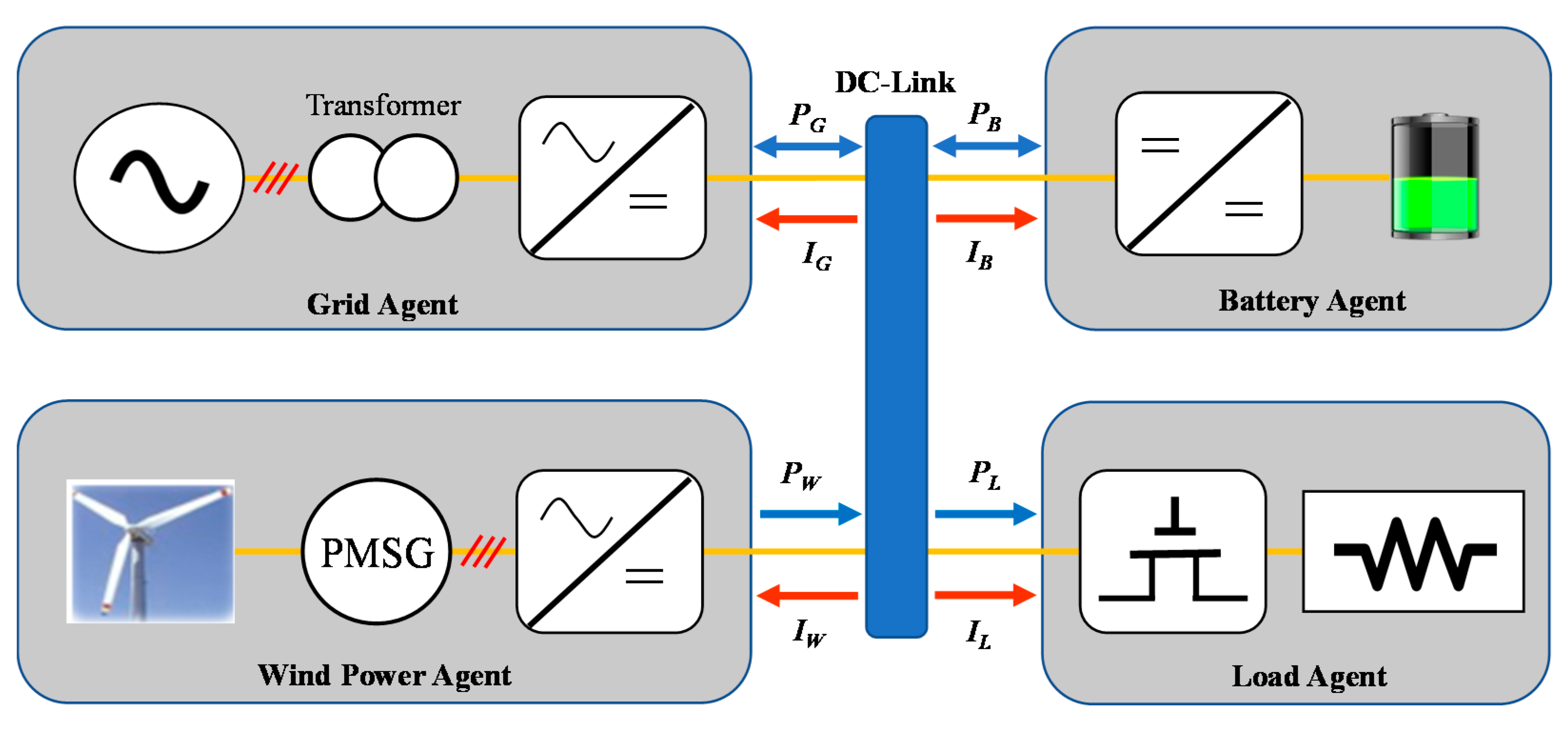
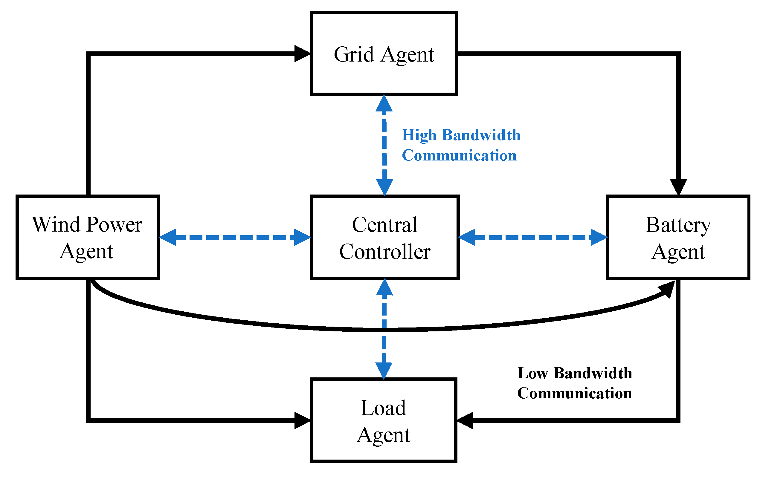
2. Configuration of DCMG System
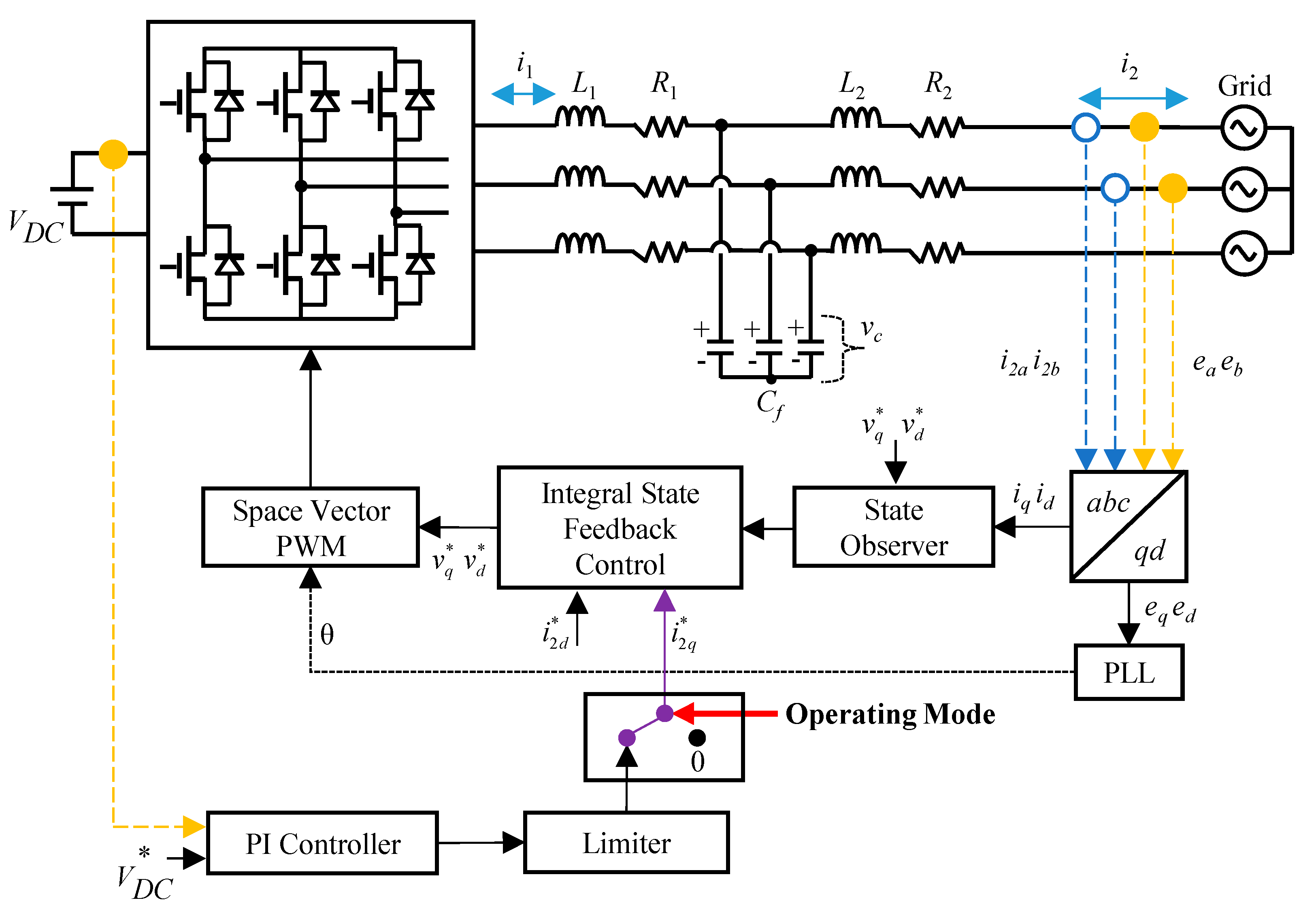
Figure 1 shows the configuration of the DCMG system considered in this study. The DCMG system consists of four agents, which are the grid agent, battery agent, wind power agent, and load agent. The grid agent and battery agent can export or import the power from the DC-link, while the wind power agent only provides the power to the DC-link and the load agent only absorbs the power from the DC-link. In this figure, PG, PB, PW, and PL denote the power from or into the grid agent, the power from or into the battery agent, the power from the wind power agent, and the power into the load agent, respectively. Figure 1 also shows the current direction of each power agent. For convenience, the reference direction of all the currents are taken as out of the DC-link. In order to connect the main grid source to the DCMG system, a transformer and a bidirectional AC-to-DC converter are employed. To supply the power from the wind turbine into the DCMG system, a permanent magnet synchronous generator (PMSG) and a unidirectional AC-to-DC converter are used. A battery is connected with a bidirectional DC-to-DC converter to exchange the power with the DCMG. In the load agent, load shedding or reconnection is achieved through electronic switches.

2.1. Grid Agent

Figure 2 shows the configuration of the grid agent. In order to damp the harmonic currents caused by the main grid source, an inductive-capacitive-inductive (LCL) filter is placed between the grid transformer and AC-to-DC converter. The parameters R1, R2, L1, L2, and Cf represent the filter resistances, filter inductances, and filter capacitance, respectively. The inverter-side current and grid-side current are denoted as i1 and i2, respectively. To regulate the currents in bidirectional way, an integral state feedback current controller with a full state observer is employed based on only the measurements of the grid currents and grid voltages [30]. The detailed control design process and observer implementation for the integral state feedback current controller in the grid-connected inverter is presented in [30,31,32].
The grid agent has three operating modes in the DCMG system, which are VDC control converter (CON) mode, VDC control inverter (INV) mode, and IDLE mode. The grid agent operates as VDC control CON mode when the wind power cannot supply the load demand, or the wind power cannot supply both the load demand and battery power in the charging mode of battery. In this operating mode, the grid agent maintains the DC-link voltage at the nominal value by injecting the required power from the grid to the DCMG. The second operating mode, namely, VDC control INV mode is used when the wind power is sufficient to supply the load demand. The grid agent also operates in this operating mode when the wind power can supply both the load demand and the maximum charging power of the battery (PB,Max,chr). In VDC control INV mode, the grid agent absorbs the surplus power from DCMG to inject it to the main grid, while regulating the DC-link voltage at the nominal value. The grid agent operates in IDLE mode instead of VDC control CON mode when the CC operates under the condition of high electricity price. In IDLE mode, the grid agent avoids the use of additional power from the grid to reduce utility cost.
When the grid agent regulates the DC-link voltage both in VDC control CON mode and VDC control INV mode, the grid agent implements two cascaded control loops as shown in Figure 2. In the outer control loop, the DC-link voltage controller is designed by using the proportional-integral (PI) controller to generate the current reference. Otherwise, the current reference is also generated as zero according to the operating modes of the grid agent. The inner control loop is designed to control the grid-side currents by using the integral state feedback control and full state observer. The full state observer estimates the system states from the system model and the measurement of the grid currents and grid voltages in the synchronous reference frame (SRF). The voltage references from the inner control loop are applied through the space vector pulse width modulation (PWM) modulation to generate the converter drive signals.

2.2. Battery Agent

Figure 3 shows the configuration of the battery agent. The battery is connected to the DCMG system with an inductive (L) filter and interleaved bidirectional DC-to-DC converter for the purpose of reducing current ripples. The battery agent has four operating modes which are VDC control by charging, VDC control by discharging, charge with the maximum allowable current (IB,Max), and IDLE mode. The battery agent operates in VDC control mode by charging if a fault occurs in the grid, and the wind power generation PW is higher than load demand PL. This operating mode is also chosen when the battery SOC is lower than the minimum SOC level, SOCmin, and PW is lower than PL. Under the condition that PW is lower than PL, and the grid agent cannot operate in VDC control CON mode, the battery agent operates in VDC control mode by discharging. When the battery SOC is less than the maximum SOC level (SOCmax) and the grid agent is connected to the DCMG, the battery operates in charge with IB,Max. This operating mode increases the battery SOC as fast as possible. The battery agent operates with IDLE mode when the battery SOC is greater than SOCmax and other power agents operate with VDC control mode. This operating mode maintains the battery SOC level without exchanging the power with the DCMG.
To implement the power flow control, the battery agent uses two PI controllers in the outer control loop and inner control loop. Similar to the grid agent, the outer control loop regulates the DC-link voltage stably and produces the current reference of the battery agent. The inner control loop controls the battery charging/discharging currents in a bidirectional way. In addition to the battery current reference, the inner control loop uses the information on the battery current feedback, the battery SOC, and the operating modes of the battery agent. If the battery agent operates in VDC control mode by charging or discharging, the battery current reference is determined from the outer PI control loop for the DC-link voltage regulation. The battery current reference is selected as IB,Max when the battery agent operates in charge with IB,Max. Otherwise, the battery current reference is set to zero for IDLE mode operation of the battery agent.

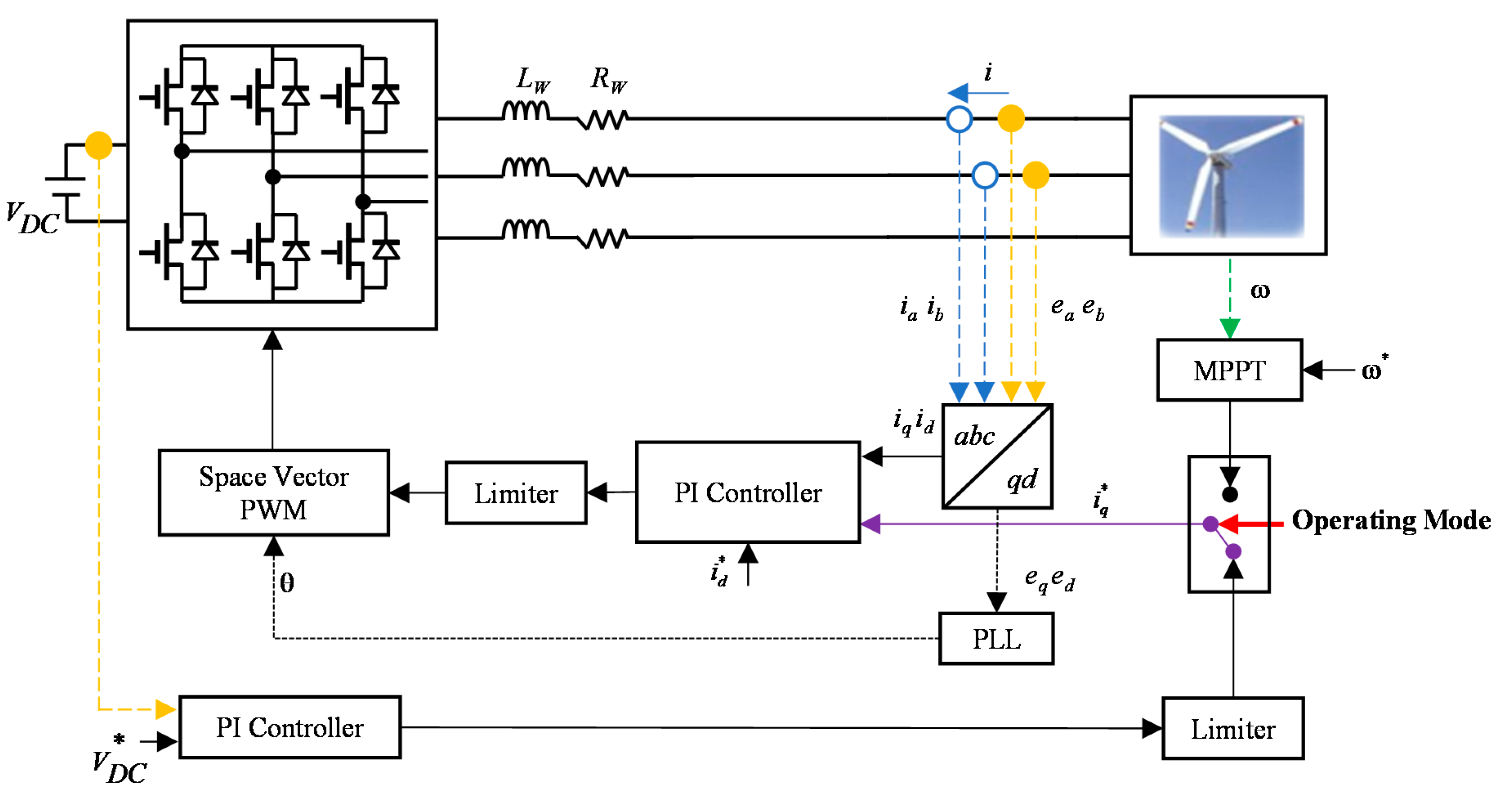
2.3. Wind Power Agent
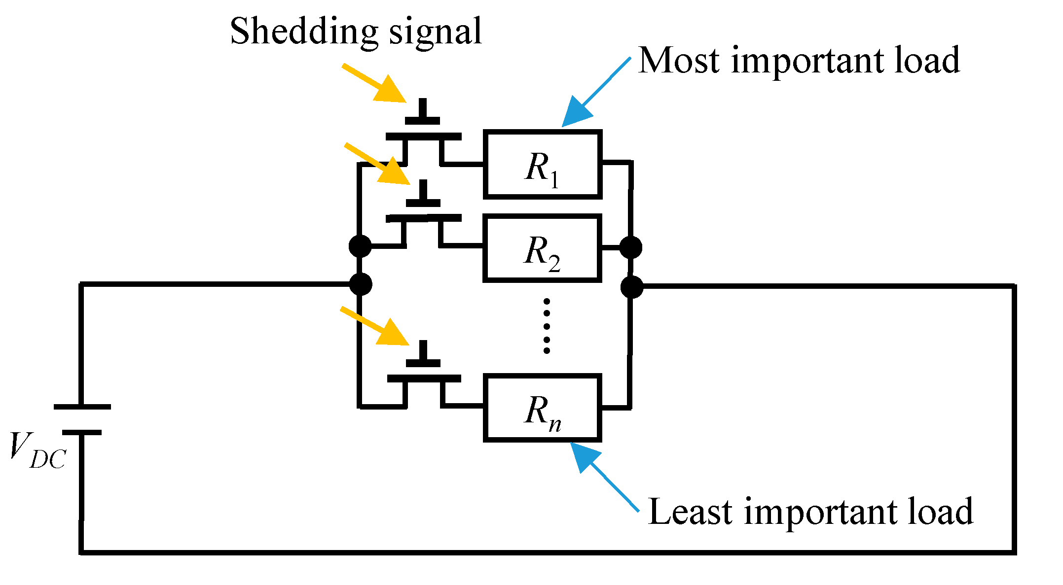
Figure 4 shows the configuration of the wind power agent. An L filter is interfaced between the PMSG and unidirectional AC-to-DC converter, and the output of AC-to-DC converter is connected to the DC-link. The wind power agent has two operating modes which are the maximum power point tracking (MPPT) mode and VDC control mode. The MPPT mode in which the wind power agent operates mostly aims to draw the maximum power from the wind turbine. On the other hand, when the wind power is higher than the load demand and other power agents cannot absorb the surplus power from the wind power, the wind power agent initiates VDC control mode to maintain the DC-link voltage of DCMG reliably. The VDC control mode is implemented by two cascaded control loops, i.e., the outer loop PI controller for the DC-link voltage regulation and inner loop synchronous PI decoupling current controller. The MPPT mode is implemented by the MPPT algorithm, PI speed controller, and inner current control loop.

2.4. Load Agent

Figure 5 shows the configuration of the load agent. In a critical situation, the load agent can shed unnecessary load to prevent the DCMG from collapsing. After the termination of a critical situation, the load agent may reconnect the shedded load through the load reconnection algorithm. The load shedding algorithm is activated when all the agents cannot provide the demanded power of load. In this condition, the load agent disconnects load one by one from the least important load. This process lasts until the system power balance of DCMG is ensured by supplying the necessary load demand at some point. When the grid is reconnected to DCMG or the battery has a sufficient SOC level, the load reconnection algorithm is initiated to reconnect the shedded load [16].

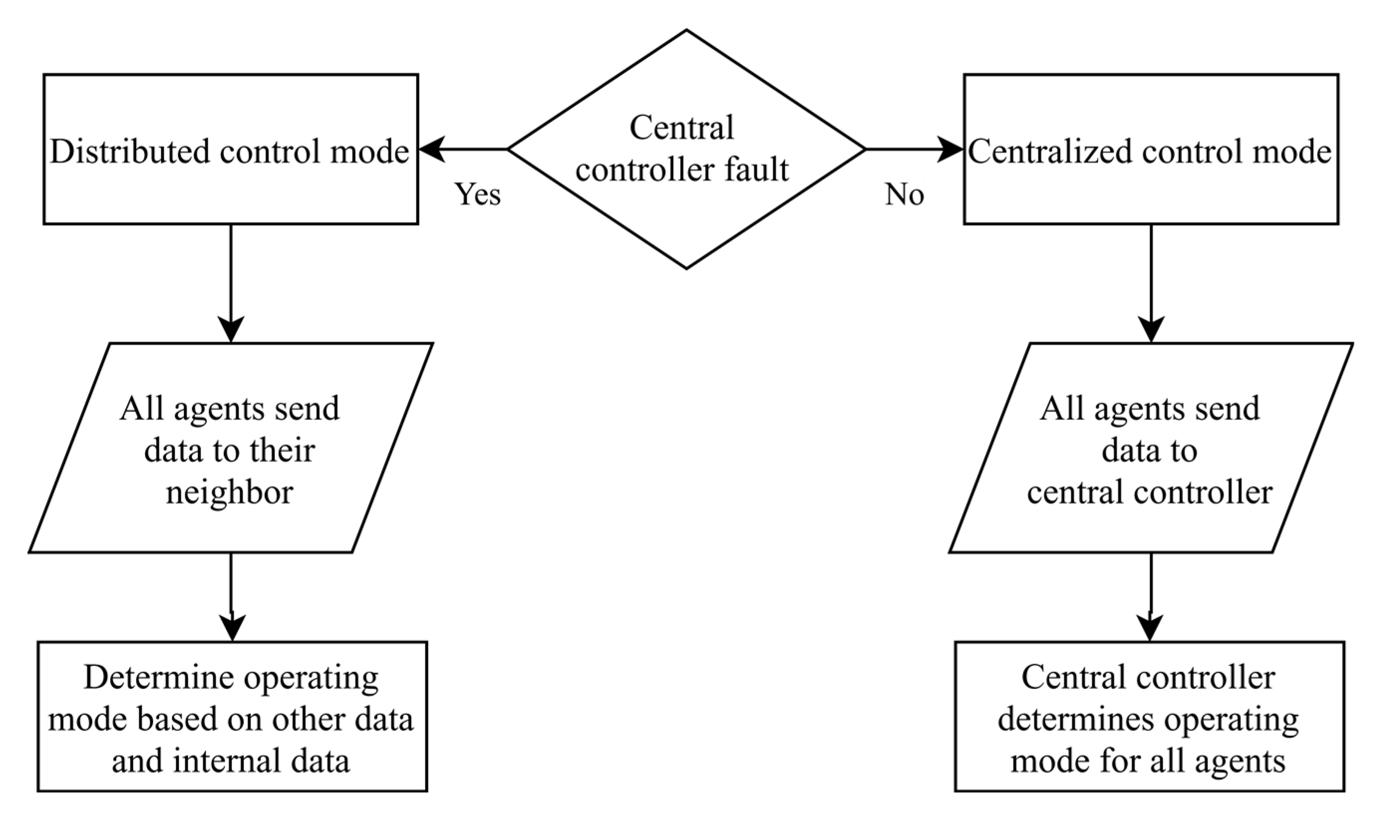
3. Proposed Hybrid DCMG Control Architecture and Power Flow Control Strategy

3.1. Hybrid DCMG Architecture

Figure 6 shows the concept of a hybrid control architecture in the DCMG system. In the hybrid control architecture, the centralized and distributed control schemes are combined. In this figure, the blue dashed line represents an HBC link for the centralized control architecture, while the black solid line represents an LBC link for the distributed control architecture. The exchange of information between the CC and power agents in the centralized control architecture is achieved through the HBC link. On the contrary, all the power agents exchange the information with adjacent neighbors in the distributed control architecture by using one-bit binary data format through the LBC link. In the centralized control of DCMG, the CC collects the information from all the power agents, processes the acquired data, and determines the operating modes of all the power agents to achieve a global optimum solution of the DCMG system. On the other hand, the distributed control of DCMG aims to improve the system reliability and robustness against a fault in the communication link.
In this study, the control mode transition between the centralized control and distributed control is determined based on the availability of the CC. Figure 7 describes the control mode transition in the hybrid DCMG architecture. During the normal condition without the CC fault, the CC operates the entire DCMG system by the centralized control architecture. Once a fault occurs in the CC, the distributed control takes control to operate the DCMG system.
In the centralized control mode, the data is exchanged between the CC and all power agents. All the power agents send specific data to the CC through the HBC link. At the same time, the CC also investigates the electricity price condition from the external sources like the internet. Based on the acquired information, the CC makes the best decision for the operating mode of all agents. Finally, the CC sends data which contains the agent operating mode along with a control signal (CS) to all the agents. Each power agent uses the CS value to determine the operation by the centralized control mode (CS signal is high) or distributed control mode (CS signal is low). When the CS signal is high, all the agents obviously use the operating mode given by the CC. On the other hand, when the CS signal is low, all the agents determine the operating modes based on the agent internal data and received information through the LBC link. In the distributed control mode, all the agents send specific data in a one-bit binary format to the adjacent neighbors. In this scheme, the data transfer by the HBC and LBC methods is accomplished every control period.

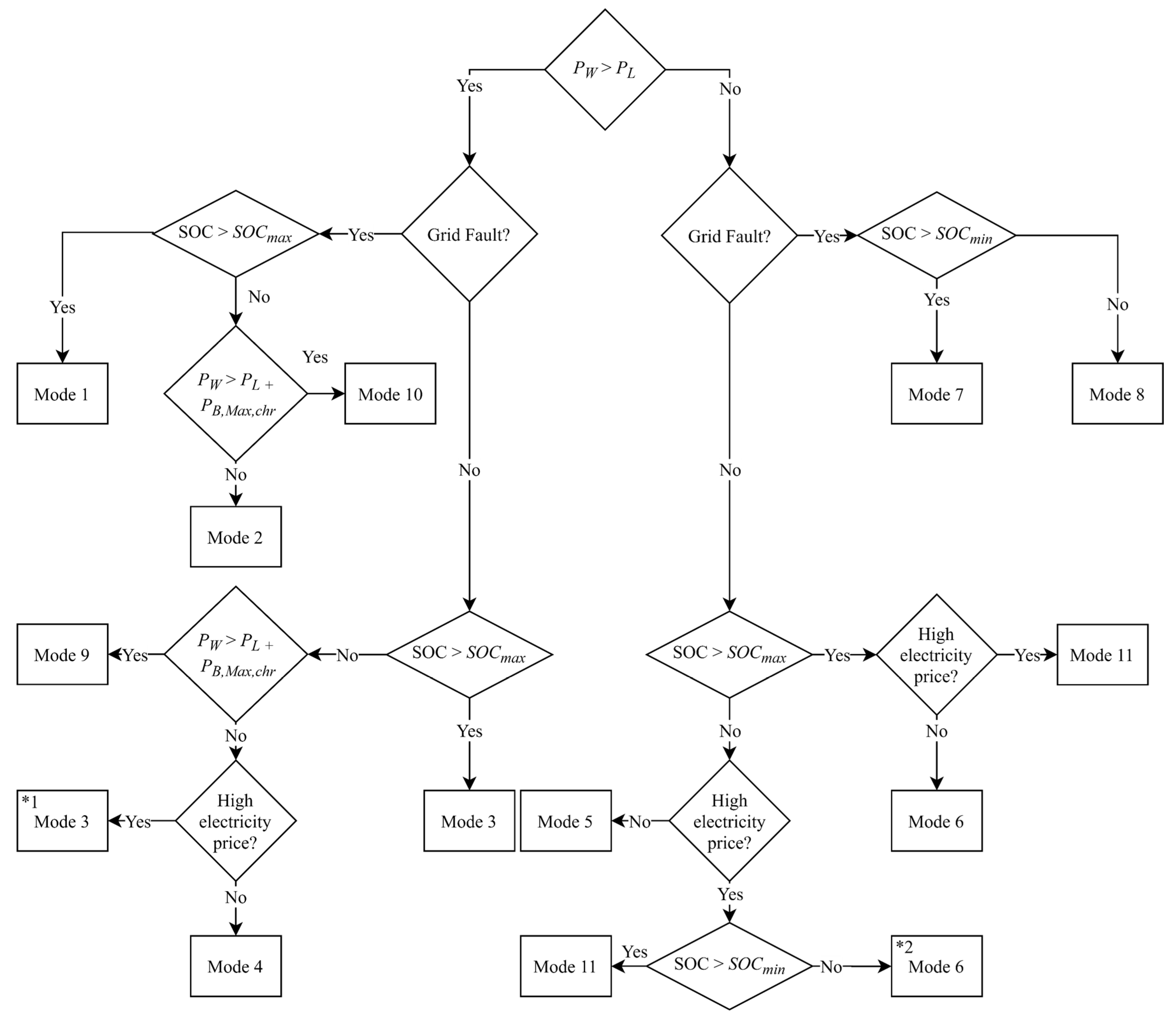
3.2. Power Flow Control Strategy

The power flow control strategy in the hybrid DCMG architecture is autonomously and reliably determined under both the centralized control and distributed control by using the relationship of supply-demand power. To determine the operating modes of power agents, several conditions and key parameters such as the availability of the CC and grid agent, battery SOC level, generated power from the wind power agent, and electricity price are primarily considered. In the proposed hybrid DCMG control scheme, the distributed control mode is composed of ten operating modes as the power flow control strategy. In the centralized control mode, an additional operating mode is added for the power flow control to consider explicitly the constraint of electricity price. Figure 8 shows the power flow control strategy in the distributed control mode. The detailed operating modes of each power agent for power flow control are listed in Table 1.
The power flow control strategy of DCMG in the distributed control mode is explained as follows.
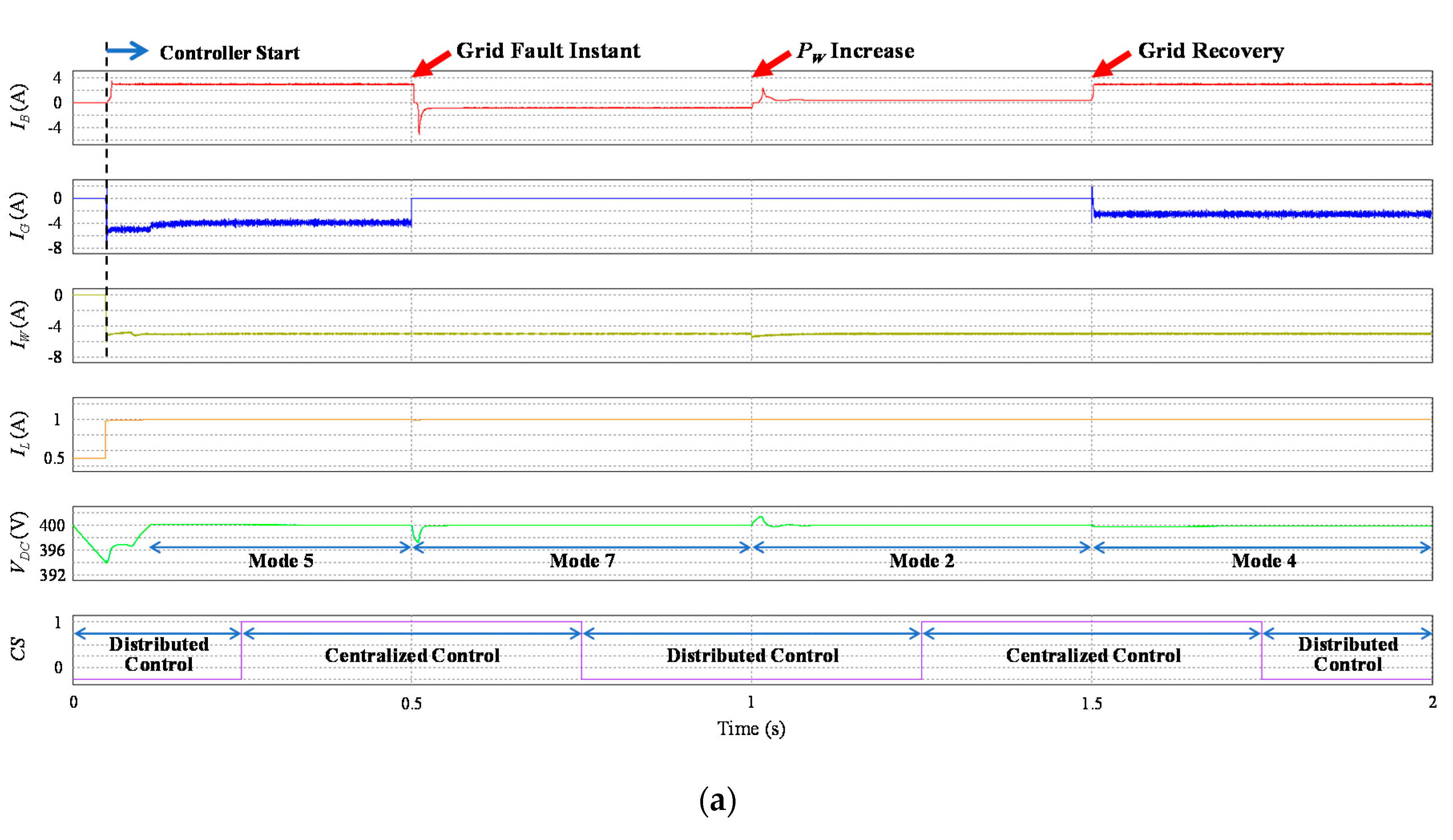
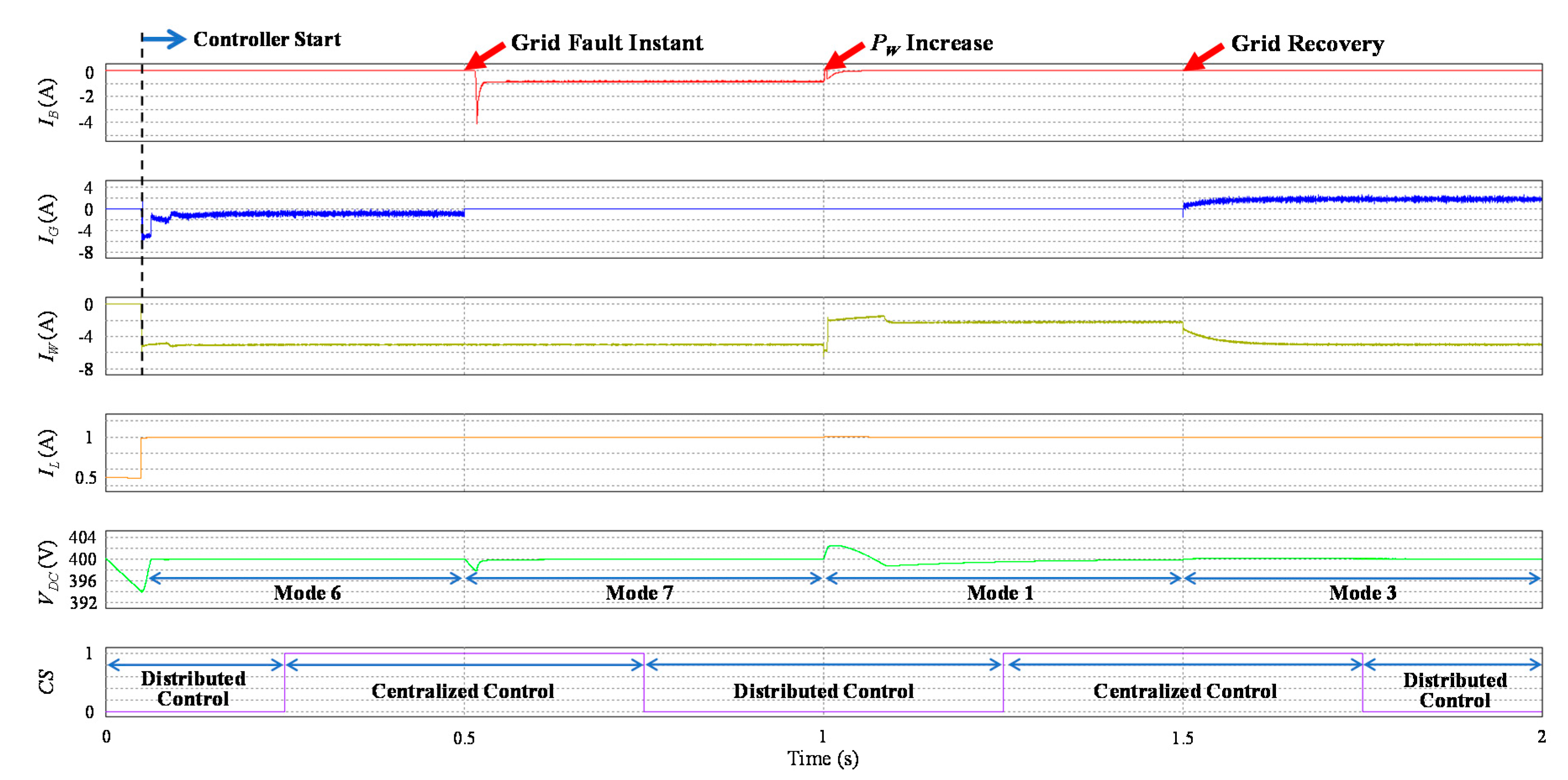
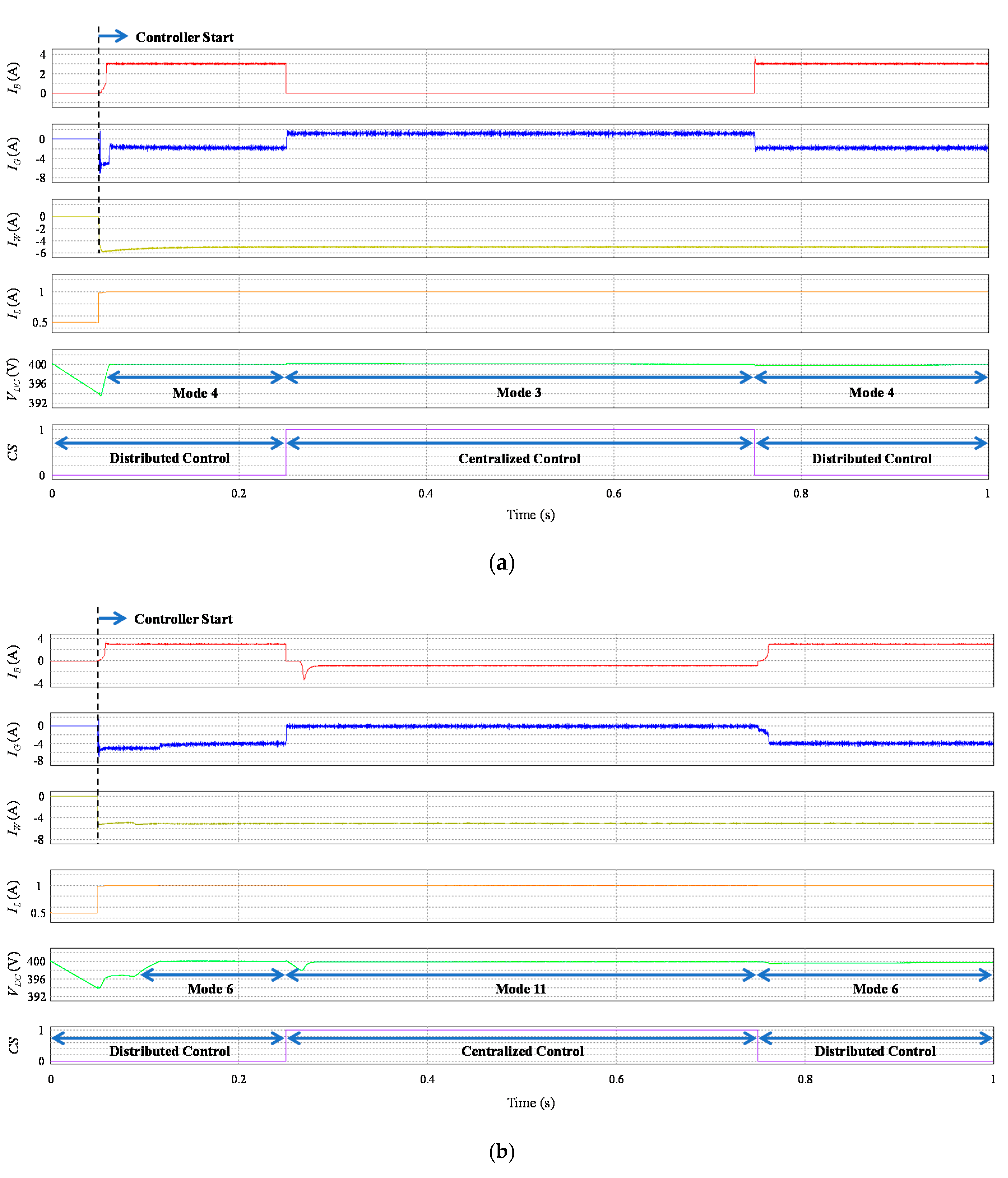
  • Operating mode 1: This operating mode occurs when the generated wind power PW is higher than the required load power demand PL and the battery SOC is higher than SOCmax under a fault in the grid agent. Because PW cannot be absorbed by other agents, the operating mode of the wind power agent is changed into VDC control mode while the battery agent is in IDLE mode.
  • Operating mode 2: This operating mode is selected when the generated wind power PW is higher than the required load demand PL, and the battery is not fully charged (SOC < SOCmax) under the grid fault. This operating mode also requires an additional condition that PW is less than the sum of load demand PL and the maximum charging power of battery PB,Max,chr. In this case, the wind power agent operates with the MPPT mode and the battery agent operates with the VDC control mode by charging to regulate the DC-link voltage.
  • Operating mode 3: This operating mode is used when the grid agent is normal, the generated wind power PW is higher than the required load demand PL, and the battery has been fully charged. In this case, the grid agent operates in VDC control INV mode to absorb the surplus power from the wind power agent which operates in the MPPT mode, while the battery agent operates in IDLE mode.
  • Operating mode 4: This operating mode requires the conditions that the grid agent is normal and the generated wind power PW is higher than the required load demand PL. Additional conditions to select this operating mode are the battery SOC is less than SOCmax, and PW is less than the sum of load demand PL and the maximum charging power of battery PB,Max,chr. In this mode, the wind power agent operates in the MPPT mode, the battery agent charges the battery with the maximum current IB,Max, and the grid agent provides the insufficient power from the grid by operating in VDC control CON mode.
  • Operating mode 5: This operating mode requires the conditions that the generated wind power PW is less than the required load demand PL and the battery SOC is less than SOCmax without a fault in the grid agent. The wind power agent draws the maximum power by operating in the MPPT mode, the battery agent charges the battery with the maximum current IB,Max, and the grid agent provides the insufficient power from the grid by operating in VDC control CON mode.
  • Operating mode 6: Operating mode 6 follows the same flow with the operating mode 5. The only difference is that this mode is used with the condition of SOC > SOCmax. In this operating mode, while both the wind power agent and grid agent maintain their operations with the same as in the operating mode 5, the battery agent changes its operation into IDLE mode.
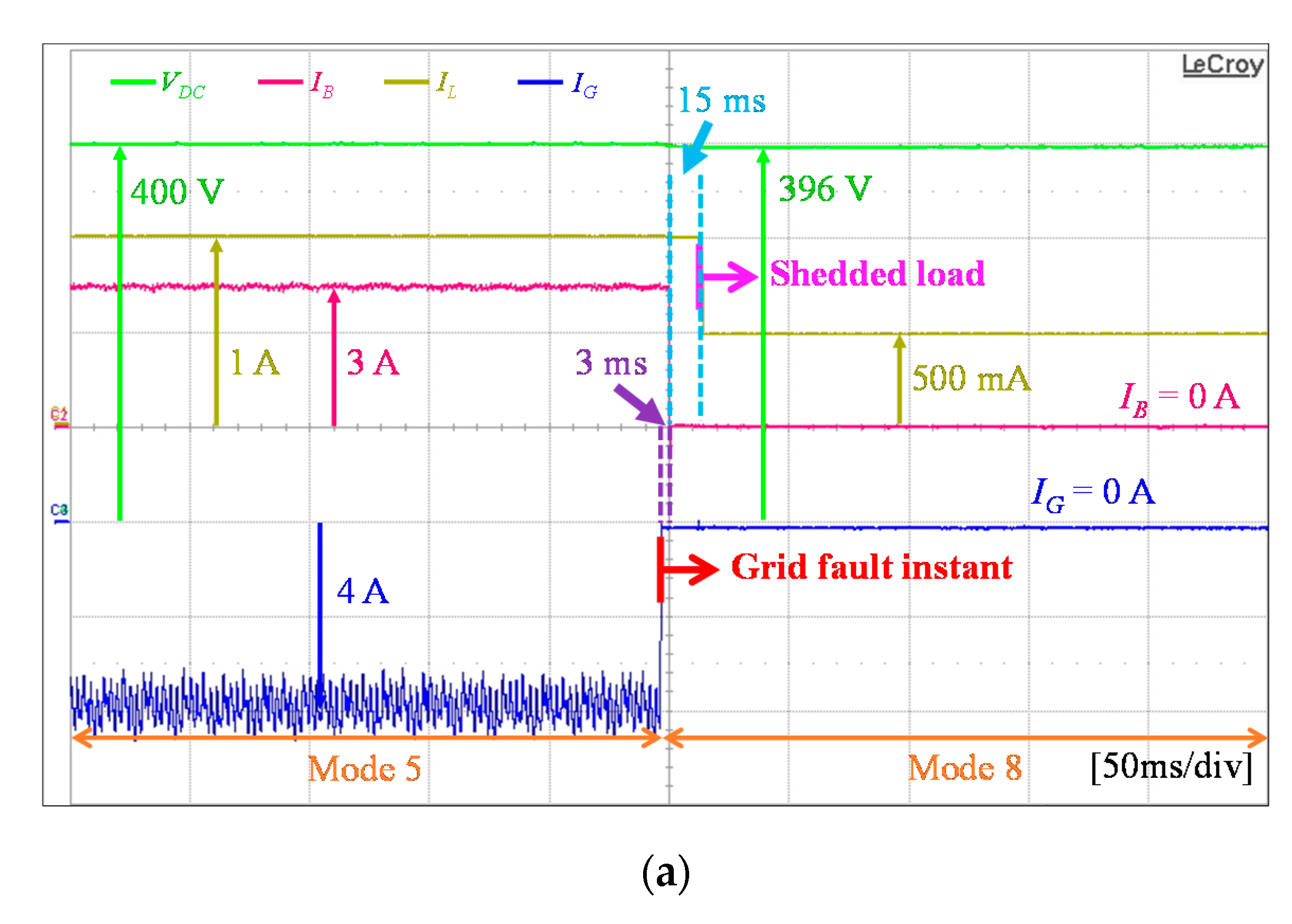
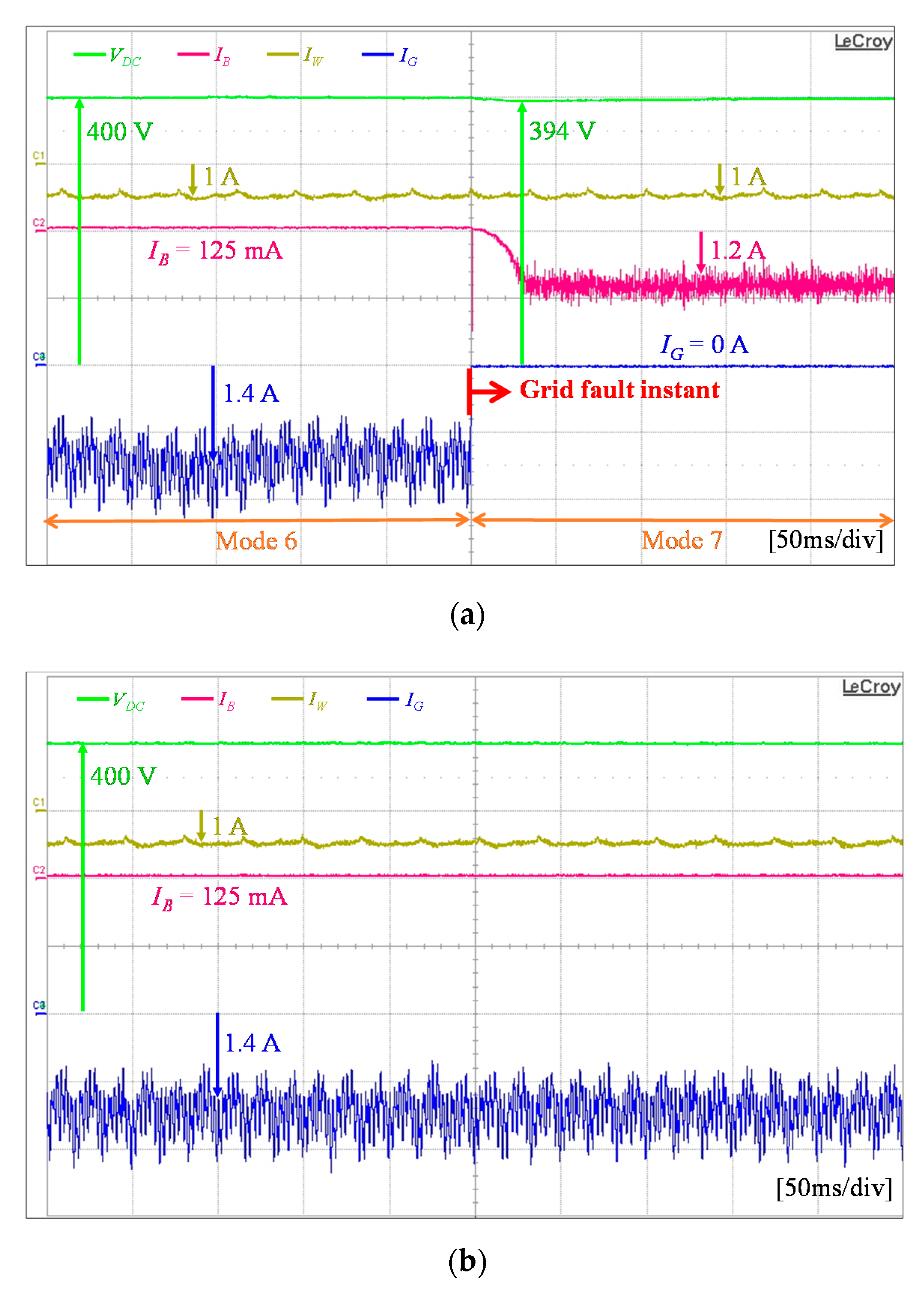
  • Operating mode 7: When the generated wind power PW is less than the required load demand PL and the battery SOC is higher than SOCmin under a fault in the grid agent, the operating mode 7 is chosen. In this mode, the wind power agent operates in the MPPT mode and the battery agent regulates the DC-link voltage by operating in VDC control by discharging.
  • Operating mode 8: Operating mode 8 follows the same flow with the operating mode 7. The only difference is that this mode is used with the condition of SOC < SOCmin. When the DCMG system operates in operating mode 7 for a long period, the battery SOC is gradually decreased and reaches the threshold level of SOCmin. In this case, the battery agent can not supply the power any more. To avoid the DCMG system collapse under this critical condition, the load shedding algorithm is activated by the load agent. The load agent removes less important loads, the battery agent is in IDLE mode, and the wind power agent changes its operating mode into VDC control mode to regulate the DC-link voltage.
  • Operating mode 9: Operating mode 9 is selected by following the same flow with the operating mode 4. The difference is that this mode is determined when the generated wind power PW is greater than the sum of load demand PL and the maximum charging power of battery PB,Max,chr. In this mode, the wind power agent still operates in the MPPT mode, the battery agent charges the battery with the maximum current IB,Max. However, contrary to operating mode 4, the grid agent provides excessive power into the grid by operating in VDC control INV mode.
  • Operating mode 10: Operating mode 10 follows the same flow with the operating mode 2. The only difference is that this mode is chosen with the condition of PW > PL + PB,Max,chr. In this condition, the generated wind power PW is higher than the required load demand PL, and the battery is not fully charged (SOC < SOCmax) under the grid fault. In addition, since PW can supply additional charging power of battery, the battery agent charges the battery with the maximum current IB,Max, and the wind power agent changes its operating mode into VDC control mode to regulate the DC-link voltage.
Figure 9 shows the power flow control strategy in the centralized control mode. The detailed operating modes of each power agent for power flow control are listed in Table 2. In the centralized control, all the operating modes are the same as those of the distributed control except for the operating mode 11. The study in [33] shows that 40% of the world wide energy usage comes from the energy consumption in building area. As the number of building is increased, many researchers have been interested in the optimization of energy savings by considering electricity price [21,22,23,24,25,26]. The research in [34] reports that an effective algorithm on EMS can reduce electricity price with the average of 23.1%. Another study in [10] shows that the use of EMS in the centralized control mode leads to cheaper electricity price than in the distributed control mode. Generally, the electricity cost saving is influenced by many factors such as the load profile, distributed power generation, pricing method, optimization algorithm, and total usage of grid power during high electricity cost condition. In spite of such a difficulty, a particular study in [35] shows the electricity cost saving up to 28% by restraining the electricity injection from the grid during high electricity cost period.
For the purpose of minimizing the customer electricity cost in the DCMG system, the electricity price constraint is also considered in this work. In the proposed scheme, the DCMG system avoids the power supplied from the grid during periods of high electricity price, absorbing the least power only in the critical condition to prevent the system from collapsing. In the presented power flow control strategy, contrary to the distributed control, there is additional operating mode 3 (denoted by *1) in the centralized control mode by considering the constraint of electricity price. As shown in the left part of Figure 9 for the case PW > PL, the high electricity price condition in the centralized control changes the DCMG operation from operating mode 4 to operating mode 3. Whereas the operating mode 4 is selected for the DCMG operation in the normal electricity price condition, the DCMG system changes its operation into the operating mode 3 under high electricity price condition to avoid additional cost. Instead of operating converter mode to supply the power from the grid, the grid agent operates in inverter mode in operating mode 3 to avoid the power supply from the grid.
Based on the constraint of electricity price, the operating mode 11 is considered for the DCMG operation. The first condition to choose the operating mode 11 follows the same flow with the operating mode 6. The utility condition having high electricity price divides the DCMG operation into the operating mode 6 and operating mode 11. Instead of operating converter mode to supply the power from the grid, the grid agent operates in IDLE mode to avoid the use of power from the grid. The second condition to choose the operating mode 11 follows the same flow with the operating mode 5. Because of high electricity price condition, the DCMG selects the operating mode 11 rather than operating mode 5 to operate the grid agent in IDLE mode instead of converter mode. Similarly, there is additional operating mode 6 (denoted by *2) by considering the constraint of electricity price as shown in Figure 9 for the case PW < PL. In spite of high electricity price, the grid agent supplies the power into the DCMG as converter mode only when the battery has an extremely low SOC level in this additional operating mode 6 (denoted by *2).

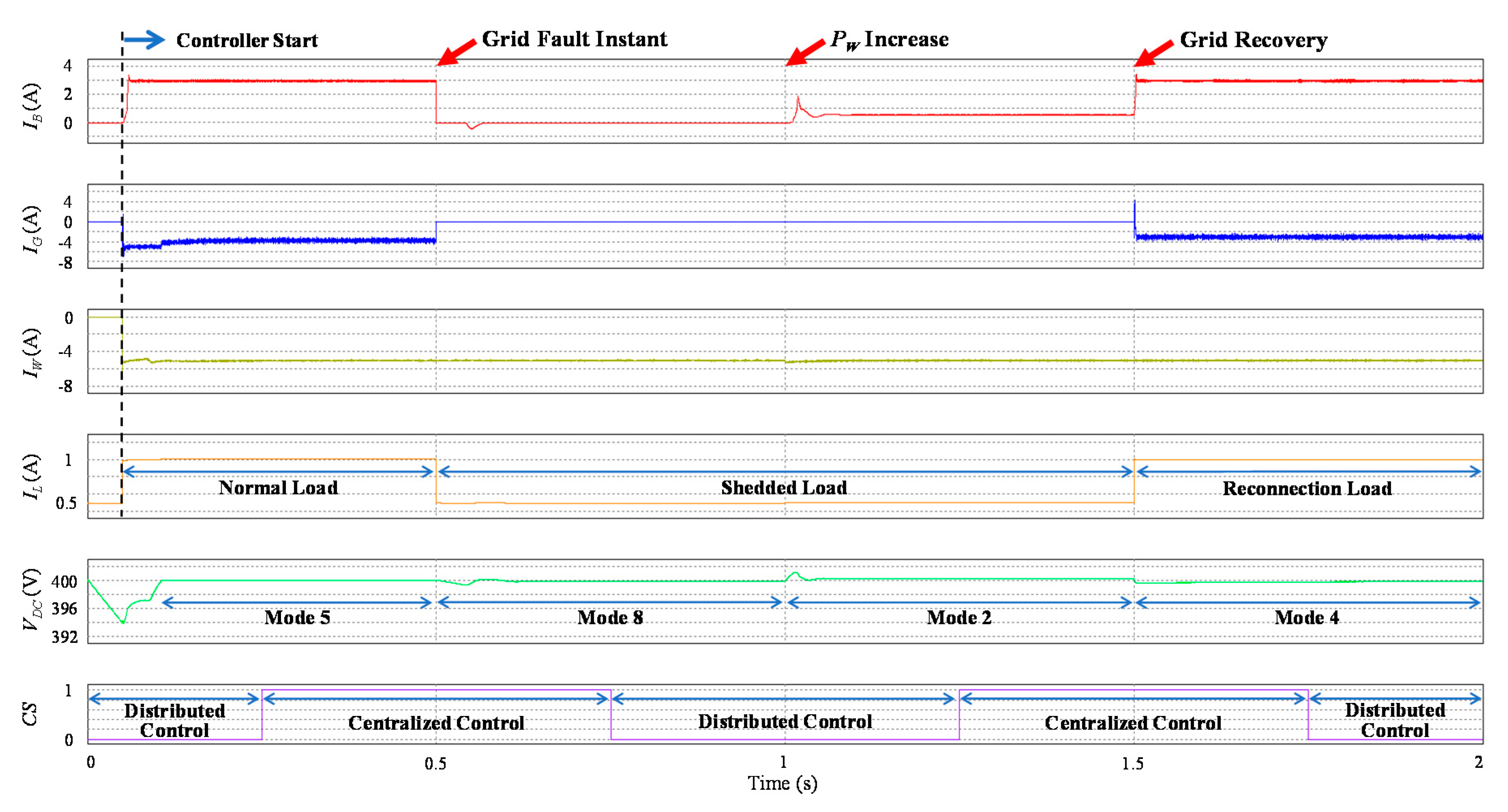
4. Simulation Results

To verify the effectiveness of the power flow strategy in the proposed hybrid DCMG control scheme under the CC fault, unreliable grid connection, and uncertainty of electricity price, the simulation has been done using the PSIM software. Table 3 lists the system parameters used for simulation. Simulations are carried out for four cases which are low battery SOC case, safe regional battery SOC case, high battery SOC case, and high electricity price case. In addition to that, the DCMG system scalability is tested by adding and removing additional power agents during a certain period.
In the simulations for three different battery SOC cases, the grid has a fault from t = 0.5 s to t = 1.5 s. It is also assumed that the CC fault occurs from t = 0 to t = 0.25 s, from t = 0.75 s to t = 1.25 s, and from t = 1.75 s to t = 2s. Initially, the generated wind power PW is less than the required load demand PL until t = 1 s. After that, PW is increased and greater than PL until t = 2 s. In these simulations, the battery agent current, the grid agent current, the wind power agent current, and the load agent current are represented as IB, IG, IW, and IL with the reference direction as in Figure 1, in which the positive current denotes the current into the agent out of the DC-link and the negative current denotes the current from the agent into the DC-link.

4.1. Case of Low Battery SOC

Figure 10 shows the simulation results of the power flow strategy in the proposed hybrid DCMG control scheme for the case of low battery SOC level. Initially, the battery SOC is less than SOCmin and all the agents start the control operation at t = 0.05 s. Since the generated wind power PW is less than the load demand PL and the battery SOC is very small without a grid fault, the DCMG system initially starts the operation with the operating mode 5, which lasts until a fault occurs in the grid at t = 0.5 s.
From this instant, the DCMG operation is changed into the operating mode 8 because both the wind power agent and battery agent cannot provide the required load demand PL. In this case, the load shedding algorithm is activated by the load agent to remove less important load while the battery agent changes the operation into IDLE mode, and the wind power agent is changed into VDC control mode to regulate the DC-link voltage.
When PW is increased higher than PL at t = 1 s, the DCMG changes its operation into the operating mode 2. In this mode, the wind power agent operates in the MPPT mode, and the battery agent regulates the DC-link voltage by operating with the VDC control mode by charging. Because the battery SOC level is still lower than SOCmin, the load reconnection algorithm cannot be activated by the load agent.
As the grid is recovered from fault at t = 1.5 s, the DCMG operation is changed into the operating mode 4 and the load reconnection is activated by the load agent at the same time. Consequently, the wind power agent maintains its operation in the MPPT mode, the battery agent charges the battery with the maximum current IB,Max, and the grid agent supplies the inadequate power by operating in VDC control CON mode.
As stated earlier, it is assumed that the CC has a fault from t = 0 to t = 0.25 s, from t = 0.75 s to t = 1.25 s, and from t = 1.75 s to t = 2s in this simulation. During the CC fault, the distributed control scheme takes the role to operate the DCMG. As shown in this result, in spite of the transition between the distributed control mode and centralized control mode, all the agents operate stably within the DCMG system without severe transient, which validates that the proposed scheme contributes to improve the system reliability and robustness against a fault in the communication link of the centralized control.

4.2. Case of Safe Regional Battery SOC

Figure 11 shows the simulation results of the power flow strategy in the proposed hybrid DCMG control scheme for the case of safe regional SOC level between SOCmin and SOCmax. Similarly, all the agents start the operation at t = 0.05 s and the DCMG initially starts with the operating mode 5. This simulation test considers two cases of PW. Figure 11a represents the case for PW < PL + PB,Max,chr, and Figure 11b represents the case for PW > PL + PB,Max,chr.
As soon as a fault occurs in the grid at t = 0.5 s, the DCMG system operation is changed into the operating mode 7 in both cases. In this mode, the wind power agent still operates in the MPPT mode and the battery agent changes its operating mode to VDC control by discharging to regulate the DC-link voltage.
As the generated wind power PW is increased at t = 1 s, the DCMG operation shows different behavior in Figure 11a,b. Under the condition of PW < PL + PB,Max,chr, the operating mode 2 is used before the grid is recovered. In this mode, the wind power agent operates in the MPPT mode and the excessive power from PW is absorbed by the battery agent which operates in VDC control mode by charging. On the other hand, under the condition of PW > PL + PB,Max,chr, the operating mode 10 is used, in which the battery agent charges the battery with the maximum current IB,Max and the wind power agent regulates the DC-link voltage by operating in VDC control mode.
When the grid is recovered t = 1.5 s, the DCMG operation is changed into the operating mode 4 in Figure 11a, and the operating mode 9 in Figure 11b. In the operating mode 4, the wind power agent maintains its operating mode, the battery agent still charges the battery with the maximum current IB,Max, and the grid agent operates in VDC control CON mode to provide the deficient power in Figure 11a. In the operating mode 9, the wind power agent operates in the MPPT mode, the battery agent maintains its operating mode, the grid agent regulates the DC-link voltage by operating in VDC control INV mode.
A smooth and reliable transition between the centralized control and distributed control caused by the CC fault is also confirmed from this simulation without affecting the overall performance.

4.3. Case of High Battery SOC

Figure 12 shows the simulation results of the proposed hybrid DCMG control scheme for the case of high battery SOC level. Because the battery has been fully charged from the beginning, the DCMG starts with the operating mode 6 and all the agents start the control t = 0.05 s. In the operating mode 6, the wind power agent operates in the MPPT mode, the battery agent is in IDLE mode, and the grid agent operates in VDC control CON mode to regulate the DC-link voltage.
In the presence of the grid fault at t = 0.5 s, while the wind power agent remains in the MPPT mode, the battery agent changes its operation into VDC control by discharging to regulate the DC-link voltage, which realizes the operating mode 7. As the generated wind power PW is increased higher than PL at t = 1 s and the battery agent is still fully charged, the wind power agent executes VDC control to regulate the DC-link voltage.
As the grid is recovered from fault at t = 1.5 s, the surplus wind power can be injected into the grid by the grid agent. At this instant, the DCMG system is controlled by the operating mode 3, in which the wind power agent changes the operation into the MPPT mode, the battery agent is still in IDLE mode, and the grid agent uses VDC control INV mode to control the DC-link voltage.
It is also evident in this simulation that the transition between the centralized control and distributed control in a hybrid DCMG structure is very smooth and stable even in the presence of a sudden fault in the CC.

4.4. Case of Electricity Price Constraint

Figure 13 shows the simulation results with the constraint of high electricity price with the assumption that the CC has the information on the time-varying price of utility. This simulation test considers two cases of PW. Figure 13a represents the case for PW > PL, and Figure 13b represents the case for PW < PL. Similar to the previous cases, all agents start the operation at t = 0.05 s in both cases.
When the generated wind power PW has the condition of PW > PL + PB,Max,chr, the DCMG starts the operation with the operating mode 4, in which the grid agent operates in VDC control CON mode. However, as soon as the distributed control is changed into the centralized control as a result of the recovery of the CC fault at t = 0.25 s, the DCMG operation is changed into the operating mode 3 as shown in Figure 13a. In the operating mode 3 of the centralized control, the battery agent changes the operation into IDLE mode to avoid the use of additional power from the grid, and the surplus power from PW is injected into the grid by operating in VDC control INV mode. If the fault occurs in the CC at t = 0.75 s, the DCMG system operation is returned to the previous operation.
With the condition of PW < PL, the DCMG starts with the operating mode 6, in which the battery agent is in IDLE mode and the grid agent operates in VDC control CON mode. As soon as the distributed control is changed into the centralized control as a result of the recovery of the CC fault at t = 0.25 s, the DCMG operation is changed into the operating mode 11 as shown in Figure 13b. As a result, the grid agent stops the converter mode operation to avoid the use of power from the grid. Instead, the deficient power in the DCMG is supplied by battery with VDC control mode by discharging. Similarly, the DCMG system operation is returned to the previous operation in case of the CC fault.

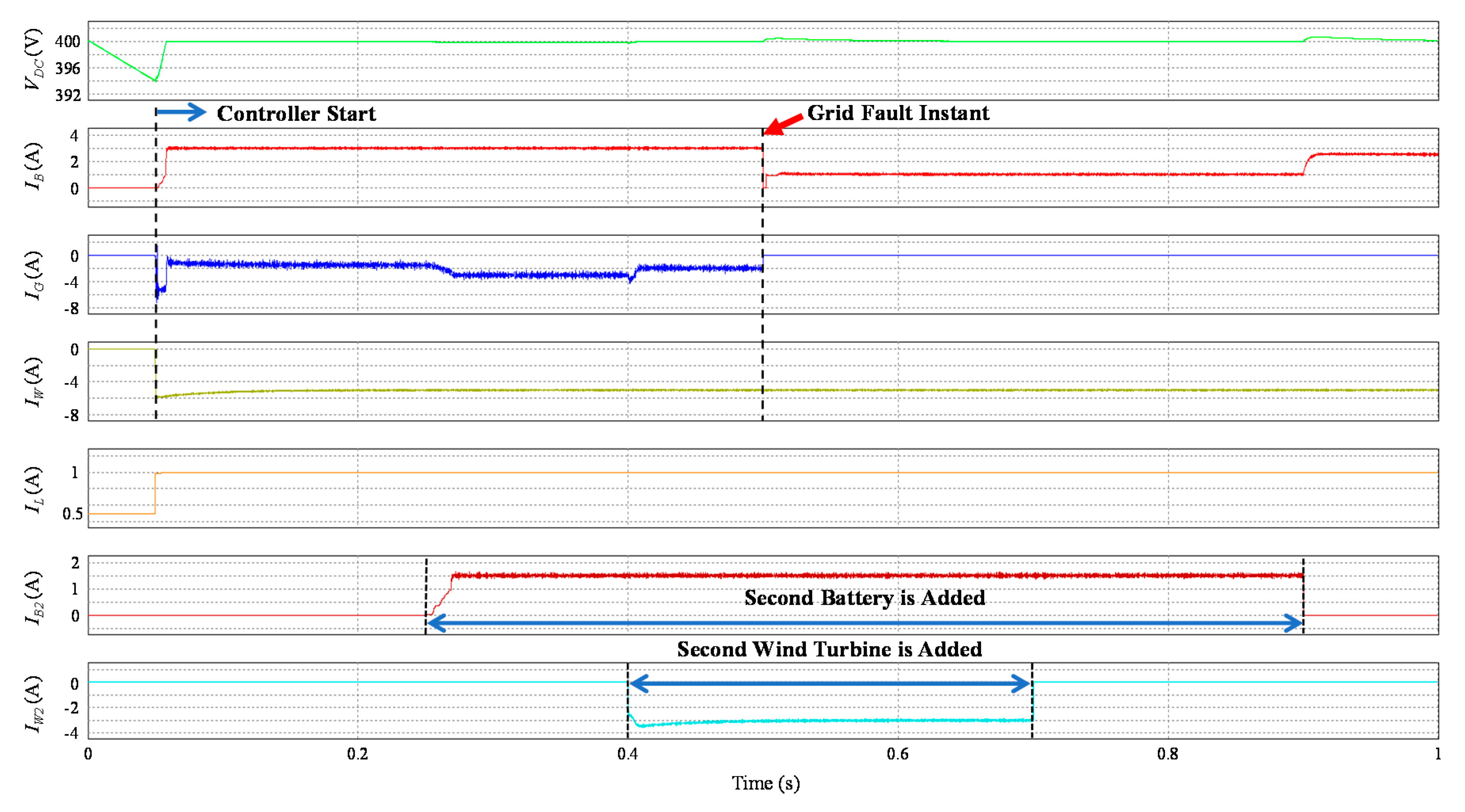
4.5. Scalability Test

The scalability of DCMG has been one of the important issues in DCMG structure. The scalability test is performed in this study based on the method in [7] by including an additional converter to the DCMG system at steady-state. Figure 14 shows the simulation result of the proposed scheme for the scalability test. In this simulation, the second battery agent is added at t = 0.3 s, and removed at t = 0.9 s. The second wind power agent is added at t = 0.4 s, and removed at t = 0.7 s. The second wind turbine operates in the MPPT mode and the second battery agent operates in charge with IB,Max mode. In addition to that, a fault occurs in the grid at t = 0.5 s, which forces the DCMG system to operate in the islanded mode. It is confirmed from this simulation that the DCMG can still maintain the DC-link voltage at the nominal value stably in spite of the addition as well as the removal of additional power agents even under the grid-connected and islanded cases.
In all the simulation tests, the maximum deviation of the DC-link voltage from the nominal value of 400 V is measured as 1.5325% in Figure 10, Figure 11a,b, Figure 12, and Figure 13b. In Figure 13a and Figure 14, it is 1.6275% and 1.5225%, respectively. The maximum deviation of the DC-link voltage from the nominal value is quite unnoticeable.

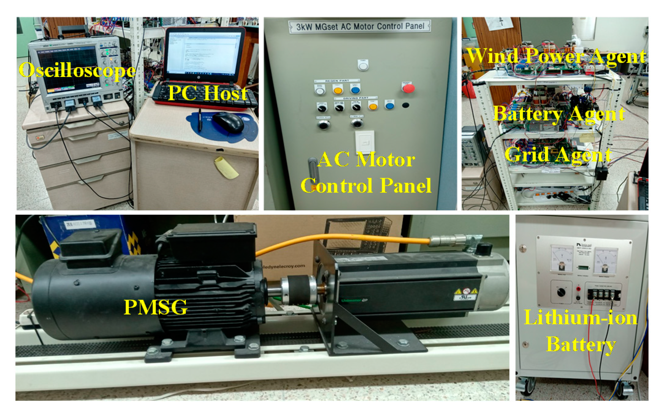
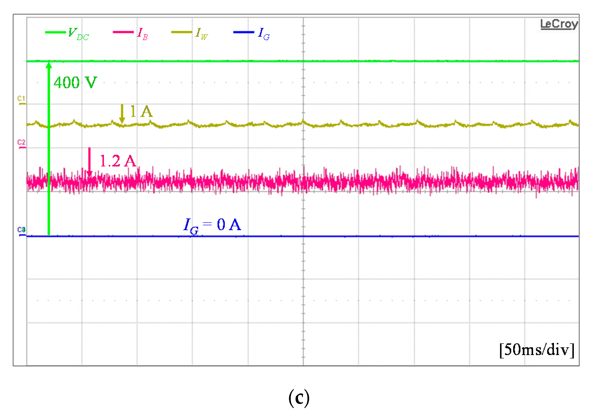
5. Experimental Results

In order to verify the effectiveness of the power flow strategy in the proposed hybrid DCMG architecture, the experiments were conducted by using a laboratory DCMG testbed system. Figure 15 shows the configuration of the experimental DCMG system. The entire system consists of a dc load and three power converters to connect the main grid source, lithium-ion battery, and wind turbine emulator to the DC-link. The wind turbine emulator is constructed by a PMSG and an induction machine drive system. DC load is composed of two 800 Ω resistors in parallel connection, and the magnetic contactor works as a switch to shed and reconnect the load. A 32-bit floating-point digital signal processor (DSP) TMS320F28335 controller is employed to implement the proposed power flow control strategy as well as to control the power converters in each agent.

5.1. Case of Low Battery SOC

Figure 16 shows the experimental results of the power flow strategy in the proposed hybrid DCMG control scheme when the battery SOC level is lower than SOCmin and the grid fault occurs. Figure 16a shows the operating mode transition from 5 to 8 caused by the grid fault. Figure 16b,c show the steady-state responses at the operating mode 5 and 8, respectively. Initially, PW is less than PL and the battery SOC level is lower than SOCmin. In the operating mode 5, the wind power agent is in the MPPT mode, the battery agent is in charge with IB,Max, and the grid agent is in VDC control CON mode for the purpose of providing the insufficient power from the grid by regulating the DC-link voltage. When a fault occurs in the grid, it is impossible for the battery agent to supply the required power to the load agent, which makes the operating mode transition from 5 to 8. As a consequence, the load agent sheds unnecessary load, the battery agent is in IDLE, and the wind power agent is in VDC control mode to maintain VDC at the nominal value. The activation of load shedding algorithm by the load agent causes 15 ms of time delay due to the coil in the magnetic contactor as is seen in Figure 16a. A small delay (3 ms) is also caused by the data transfer and observed in the experimental results. However, as can be shown in the transient response in Figure 16a, the operating mode transition is quite smooth and the DC-link voltage regulation is very stable. The steady-state responses in Figure 16b,c also validate a reliable operation of the DCMG system.

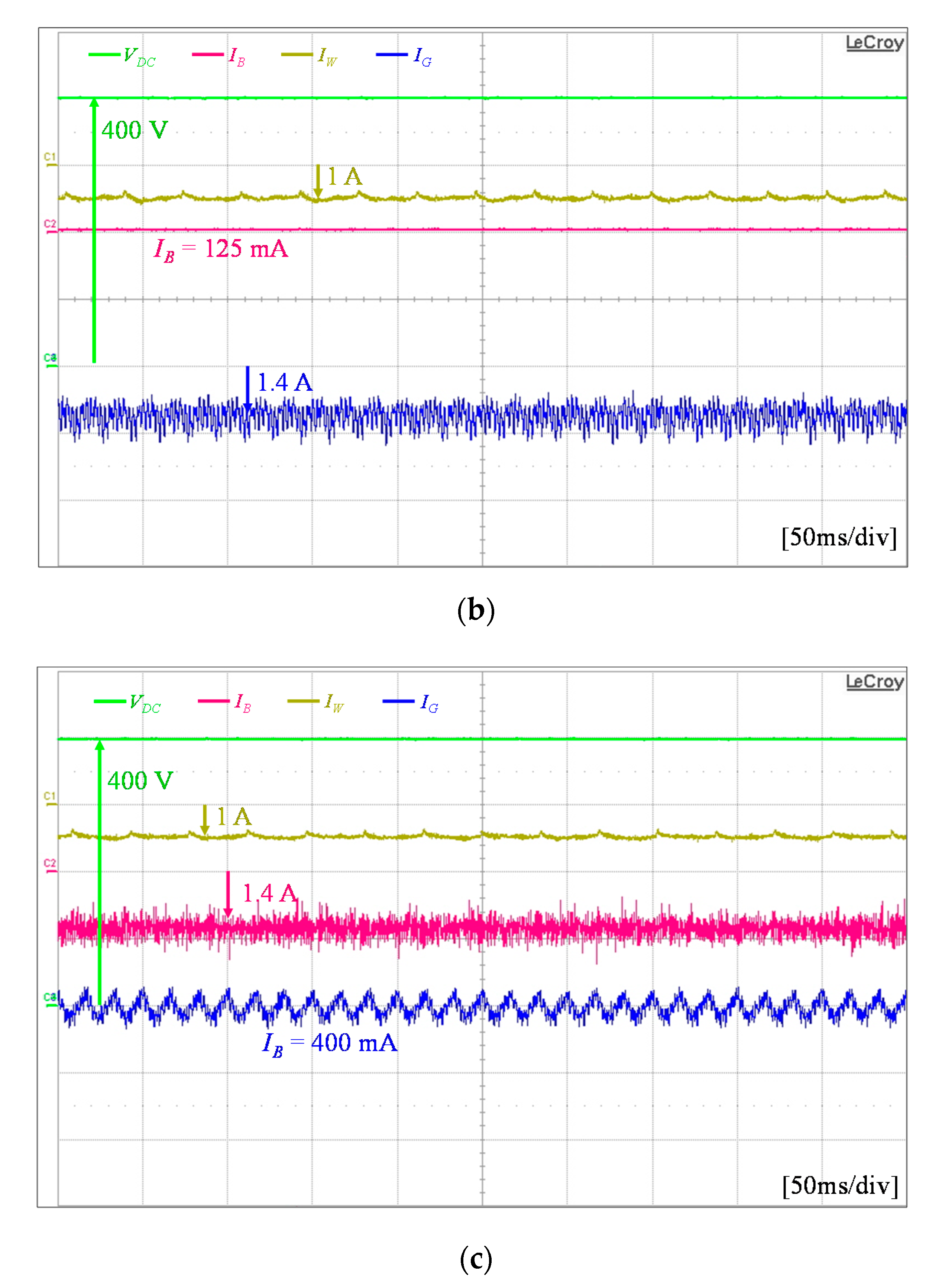
5.2. Case of Safe Regional Battery SOC

Figure 17 shows the experimental result of the power flow strategy in the proposed hybrid DCMG control scheme for the case of safe regional SOC level. Initially, the generated wind power PW is less than the load demand PL, and the battery SOC level in the middle of SOCmin and SOCmax. Without the grid fault, the DCMG starts the operation with the operating mode 5. In this mode, the wind power agent is in the MPPT mode, the battery agent is in charge with IB,Max, and the grid agent is in VDC control CON mode. When a fault occurs in the grid, the DCMG changes the operation into the operating mode 7. Figure 17a shows the operating mode transition from 5 to 7 caused by the grid fault. Figure 17b,c show the steady-state responses at the operating mode 5 and 7, respectively. As a result of the operating mode transition into 7, the battery agent executes VDC control mode by discharging to provide the load remand. These waveforms also confirm a smooth operating mode transition and stable operation of the proposed hybrid DCMG control scheme.

5.3. Case of High Battery SOC

Figure 18 shows the experimental result of the proposed hybrid DCMG control scheme for the case of high battery SOC level. Initially, the generated wind power PW is less than the load demand PL, the battery SOC is higher than SOCmax, and the grid is in the normal condition, which results in the operating mode 6. In this mode, the wind power agent is in the MPPT mode, the battery agent is in IDLE mode, and the grid agent is in VDC control CON mode. As soon as a fault occurs in the grid, the DCMG operation is changed into the operating mode 7. Figure 18a shows the operating mode transition from 6 to 7 caused by the grid fault. Figure 18b,c show the steady-state responses at the operating mode 6 and 7, respectively. As soon as the operating mode is changed, the battery agent takes the role to regulate the DC-link voltage by operating in the VDC control mode by discharging. Similarly, the usefulness of the proposed hybrid DCMG control scheme can be observed.

5.4. Case of Electricity Price Constraint

Figure 19 shows the experimental results of the proposed hybrid DCMG control scheme with the constraint of high electricity price. With the condition that the generated wind power PW is less than the load demand PL, and the battery is fully charged without the grid fault, the DCMG starts with the operating mode 6 at first. If the CC detects high electricity price condition at this instant, the grid agent operation is changed from VDC control CON mode into the IDLE mode to avoid the increase of utility cost. Instead, the battery is discharged to compensate the deficient power in the DCMG system while regulating the DC-link voltage with VDC control mode by discharging. In this case, the resultant DCMG operation is the operating mode 11. Obviously, if the electricity price is returned to the normal condition, the operation of the DCMG system is also restored into the operating mode 6. Figure 19a shows the experimental result of the DCMG operating mode transition when the CC detects high electricity price condition. Figure 19b,c show the steady-state responses at the operating mode 6 and 11, respectively.

6. Conclusions

This paper has presented an effective power flow control strategy for a hybrid control architecture of DCMG under an unreliable grid connection considering the constraint of electricity price. To overcome the limitation of the existing coordination control architectures, a hybrid control method which combines the centralized control and distributed control is applied to control DCMG. By using the hybrid control approach, a more optimal and reliable DCMG system can be constructed even though a fault occurs in the grid or the CC. The power flow control strategy is developed for the hybrid DCMG control architecture by taking the constraint of electricity price into account. In the proposed architecture, the HBC link is used in the centralized control to connect the CC with DCMG power agents. Based on the information from all the agents, the CC determines the operating modes of all the agents. On the contrary, the LBC link is employed to constitute the distributed control. To reduce the communication burden, only one-bit binary data is used to exchange the information between the agents via the LBC link. Main contributions of this paper can be summarized as follows:
(i)
A power flow control strategy for a hybrid DCMG control scheme which combines the centralized control and distributed control is proposed. The proposed scheme improves the system stability and robustness even in the presence of a fault in the communication link of the centralized control. All the power agents operate stably within the DCMG system without severe transients in spite of the transition between the distributed control and the centralized control. The DC-link voltage can be also regulated stably with the proposed scheme in both the centralized control and distributed control even during transition periods.
(ii)
By using the proposed scheme, the common single point of failure as in the centralized control can be avoided. Even when the distributed control takes control of the DCMG system because of a fault in the CC, the DCMG system stably works. Furthermore, the problems related to the lack of information exchange as in the decentralized control can be solved by means of a communication network.
(iii)
The proposed scheme proves that the hybrid DCMG control scheme can be implemented by the exchange of only a small size of data through the HBC and LBC links to exchange the information with reduced communication burden.
(iv)
In the proposed hybrid DCMG control scheme, the constraint of electricity price is also considered to develop the power flow control with the aim to minimize the consumer electricity cost.
To verify the practical usefulness of the power flow control strategy of the proposed hybrid control architecture, a prototype DCMG system has been constructed by using 32-bit floating-point DSP TMS320F28335 controller. The DCMG consists of bidirectional AC-to-DC converter to connect the grid source, unidirectional AC-to-DC converter to connect the wind turbine emulator, and bidirectional DC-to-DC converter to connect the lithium-ion battery. Comprehensive simulation and experimental results have been presented to prove the effectiveness of the proposed power flow control strategy of the hybrid control architecture, which well confirms the stable operation and overall performance of the proposed scheme.

Author Contributions

F.A.P. and K.-H.K. conceived the main concept of the microgrid control structure and developed the entire system. F.A.P. carried out the research and analyzed the numerical data with guidance from K.-H.K., F.A.P. and K.-H.K. collaborated in the preparation of the manuscript. All authors have read and agreed to the published version of the manuscript.

Funding

This research received no external funding.

Acknowledgments

This research was supported by Basic Science Research Program through the National Research Foundation of Korea (NRF) funded by the Ministry of Education (NRF-2019R1A6A1A03032119). This work was supported by the National Research Foundation of Korea (NRF) grant funded by the Korea government (MSIT) (NRF-2020R1F1A1048262).

Conflicts of Interest

The authors declare no conflict of interest.

References

  1. Rosero, C.X.; Velasco, M.; Marti, P.; Camacho, A.; Miret, J.; Castilla, M.A. Active Power Sharing and Frequency Regulation in Droop-Free Control for Islanded Microgrids Under Electrical and Communication Failures. IEEE Trans. Ind. Electron. 2020, 67, 6461–6472. [Google Scholar] [CrossRef]
  2. Pahasa, J.; Ngamroo, I. Coordinated PHEV, PV, and ESS for Microgrid Frequency Regulation Using Centralized Model Predictive Control Considering Variation of PHEV Number. IEEE Access 2018, 6, 69151–69161. [Google Scholar] [CrossRef]
  3. Mathew, P.; Madichetty, S.; Mishra, S. A Multi-Level Control and Optimization Scheme for Islanded PV Based Microgrid: A Control Frame Work. IEEE J. Photovolt. 2019, 9, 822–831. [Google Scholar] [CrossRef]
  4. Espín-Sarzosa, D.; Palma-Behnke, R.; Núñez-Mata, O. Energy Management Systems for Microgrids: Main Existing Trends in Centralized Control Architectures. Energies 2020, 13, 547. [Google Scholar] [CrossRef] [Green Version]
  5. Balog, R.S.; Weaver, W.W.; Krein, P.T. The Load as an Energy Asset in a Distributed DC SmartGrid Architecture. IEEE Trans. Smart Grid 2012, 3, 253–260. [Google Scholar] [CrossRef]
  6. Khorsandi, A.; Ashourloo, M.; Mokhtari, H. A Decentralized Control Method for a Low-Voltage DC Microgrid. IEEE Trans. Energy Convers. 2014, 9, 793–801. [Google Scholar] [CrossRef]
  7. Cook, M.D.; Parker, G.G.; Robinett, R.D.; Weaver, W.W. Decentralized Mode-Adaptive Guidance and Control for DC Microgrid. IEEE Trans. Power Deliv. 2017, 32, 263–271. [Google Scholar]
  8. Nasirian, V.; Moayedi, S.; Davoudi, A.; Lewis, F.L. Distributed Cooperative Control of DC Microgrids. IEEE Trans. Power Electron. 2015, 30, 2288–2303. [Google Scholar] [CrossRef]
  9. Kwasinki, A.; Onwuchekwa, C.N. Dynamic Behavior and Stabilization of DC Microgrids with Instantaneous Constant-Power Loads. IEEE Trans. Power Electron. 2011, 26, 822–834. [Google Scholar] [CrossRef]
  10. Feng, X.; Shekhar, A.; Yang, F.; Hebner, R.E.; Bauer, P. Comparison of Hierarchical Control and Distributed Control for Microgrid. Elect. Power Compon. Syst. 2017, 45, 1043–1056. [Google Scholar] [CrossRef]
  11. Diaz, N.L.; Luna, A.C.; Vasquez, J.C.; Guerrero, J.M. Centralized Control Architecture for Coordination of Distributed Renewable Generation and Energy Storage in Islanded AC Microgrids. IEEE Trans. Power Electron. 2017, 32, 5202–5213. [Google Scholar]
  12. Katiraei, F.; Iravani, R.; Hatziargyriou, N.; Dimeas, A. Microgrids management. IEEE Power Energy Mag. 2008, 6, 54–65. [Google Scholar]
  13. Xu, Q.; Xiao, J.; Wang, P.; Wen, C. A Decentralized Control Strategy for Economic Operation of Autonomous AC, DC, and Hybrid AC/DC Microgrids. IEEE Trans. Energy Convers. 2017, 32, 1345–1355. [Google Scholar]
  14. Liu, W.; Gu, W.; Sheng, W.; Meng, X.; Wu, Z.; Chen, W. Decentralized Multi-Agent System-Based Cooperative Frequency Control for Autonomous Microgrids with Communication Constraints. IEEE Trans. Sustain. Energy 2014, 5, 446–456. [Google Scholar]
  15. Karimi, Y.; Oraee, H.; Golsorkhi, M.S.; Guerrero, J.M. Decentralized Method for Load Sharing and Power Management in a PV/Battery Hybrid Source Islanded Microgrid. IEEE Trans. Power Electron. 2017, 32, 3525–3535. [Google Scholar]
  16. Nguyen, T.V.; Kim, K.H. Power Flow Control Strategy and Reliable DC-Link Voltage Restoration for DC Microgrid under Grid Fault Conditions. Sustainability 2019, 11, 3781. [Google Scholar]
  17. Mehdi, M.; Kim, C.H.; Saad, M. Robust Centralized Control for DC Islanded Microgrid Considering Communication Network Delay. IEEE Access 2020, 8, 77765–77778. [Google Scholar]
  18. Nguyen, T.V.; Kim, K.-H. An Improved Power Management Strategy for MAS-Based Distributed Control of DC Microgrid under Communication Network Problems. Sustainability 2020, 12, 122. [Google Scholar]
  19. Mathew, P.; Madichetty, S.; Mishra, S. A Multilevel Distributed Hybrid Control Scheme for Islanded DC Microgrids. IEEE Syst. J. 2019, 13, 4200–4207. [Google Scholar]
  20. Mohamed, Y.A.I.; Radwan, A.A. Hierarchical Control System for Robust Microgrid Operation and Seamless Mode Transfer in Active Distribution Systems. IEEE Trans. Smart Grid 2011, 2, 352–362. [Google Scholar]
  21. Zhou, L.; Zhang, Y.; Lin, X.; Li, C.; Cai, Z.; Yang, P. Optimal Sizing of PV and BESS for a Smart Household Considering Different Price Mechanisms. IEEE Access 2018, 6, 41050–41059. [Google Scholar]
  22. Wu, X.; Hu, X.; Yin, X.; Zhang, C.; Qian, S. Optimal Battery Sizing of Smart Home via Convex Programming. Energy 2017, 45, 444–453. [Google Scholar]
  23. Hemmati, R.; Saboori, H. Stochastic Optimal Battery Storage Sizing and Scheduling in Home Energy Management Systems Equipped with Solar Photovoltaic Panels. Energy Build. 2017, 152, 290–300. [Google Scholar]
  24. Hemmati, R. Technical and Economic Analysis of Home Energy Management System Incorporating Small-Scale Wind Turbine and Battery Energy Storage System. J. Clean. Prod. 2017, 159, 106–118. [Google Scholar]
  25. Wang, H.; Fang, H.; Yu, X.; Liang, S. How Real Time Pricing Modifies Chinese Households’ Electricity Consumption. J. Clean. Prod. 2018, 178, 776–790. [Google Scholar]
  26. Newsham, G.R.; Bowker, B.G. The Effect of Utility Time-Varying Pricing and Load Control Strategies on Residential Summer Peak Electricity Use: A Review. Energy Policy 2010, 38, 3289–3296. [Google Scholar]
  27. Zhou, B.; Yang, R.; Li, C.; Wang, Q.; Liu, J. Multiobjective Model of Time-of-Use and Stepwise Power Tariff for Residential Consumers in Regulated Power Markets. IEEE Syst. J. 2018, 12, 2676–2687. [Google Scholar]
  28. Li, C.; Tang, S.; Cao, Y.; Xu, Y.; Li, Y.; Li, J.; Zhang, R. A New Stepwise Power Tariff Model and Its Application for Residential Consumers in Regulated Electricity Markets. IEEE Trans. Power Syst. 2013, 28, 300–308. [Google Scholar]
  29. Lu, X.; Guerrero, J.M.; Sun, K.; Vasquez, J.C. An Improved Droop Control Method for DC Microgrids Based on Low Bandwidth Communication with DC Bus Voltage Restoration and Enhanced Current Sharing Accuracy. IEEE Trans. Power Electron. 2014, 29, 1800–1812. [Google Scholar]
  30. Yoon, S.J.; Lai, N.B.; Kim, K.H. A Systematic Controller Design for a Grid-connected Inverter with LCL Filter Using a Discrete-time Integral State Feedback Control and State Observer. Energies 2018, 11, 437. [Google Scholar]
  31. Tran, T.V.; Yoon, S.-J.; Kim, K.-H. An LQR-Based Controller Design for an LCL-Filtered Grid-Connected Inverter in Discrete-Time State-Space under Distorted Grid Environment. Energies 2018, 11, 2062. [Google Scholar] [CrossRef] [Green Version]
  32. Bimarta, R.; Tran, T.V.; Kim, K.-H. Frequency-Adaptive Current Controller Design Based on LQR State Feedback Control for a Grid-Connected Inverter under Distorted Grid. Energies 2018, 11, 2674. [Google Scholar] [CrossRef] [Green Version]
  33. Kolokotsa, D.; Rovas, D.; Kosmatopoulos, E.; Kalaitzakis, K. A Roadmap towards Intelligent Net Zero- and Positive-Energy Buildings. Sol. Energy 2011, 85, 3067–3084. [Google Scholar] [CrossRef]
  34. Beaudin, M.; Zareipour, H. Home Energy Management Systems: A Review of Modelling and Complexity. Renew. Sustain. Energy Rev. 2015, 45, 318–335. [Google Scholar]
  35. Boynuegri, A.R.; Yagcitekin, B.; Baysal, M.; Karakas, A.; Uzunoglu, M. Energy management algorithm for smart home with renewable energy sources. In Proceedings of the 4th International Conference on Power Engineering, Energy and Electrical Drives, Istanbul, Turkey, 13–17 May 2013. [Google Scholar]
Figure 1. Configuration of DC microgrid (DCMG).
Sustainability 12 07628 g001
Figure 2. Configuration of grid agent.
Sustainability 12 07628 g002
Figure 3. Configuration of battery agent.
Sustainability 12 07628 g003
Figure 4. Configuration of wind power agent.
Sustainability 12 07628 g004
Figure 5. Configuration of load agent.
Sustainability 12 07628 g005
Figure 6. Concept of the hybrid DCMG control architecture.
Sustainability 12 07628 g006
Figure 7. Control mode transition in the hybrid DCMG architecture.
Sustainability 12 07628 g007
Figure 8. Power flow control strategy in the distributed control mode.
Sustainability 12 07628 g008
Figure 9. Power flow control strategy in the centralized control mode.
Sustainability 12 07628 g009
Figure 10. Simulation results for the case of battery state-of-charge (SOC) level lower than the minimum value.
Sustainability 12 07628 g010
Figure 11. Simulation results for the case of safe regional battery SOC level: (a) Case of PW > PL and PW < PL + PB,Max,chr; (b) Case of PW > PL and PW > PB,Max,chr.
Sustainability 12 07628 g011aSustainability 12 07628 g011b
Figure 12. Simulation results for the case of battery SOC level higher than the maximum value.
Sustainability 12 07628 g012
Figure 13. Simulation results with the constraint of high electricity price. (a) Operating mode transition for PW > PL; (b) Operating mode transition for PW < PL.
Sustainability 12 07628 g013
Figure 14. Simulation result for scalability when other agents are added into DCMG.
Sustainability 12 07628 g014
Figure 15. Configuration of the experimental DCMG system.
Sustainability 12 07628 g015
Figure 16. Experimental results when the battery SOC level is lower than SOCmin and the grid fault occurs. (a) Operating mode transition from 5 to 8; (b) Steady-state response at operating mode 5; (c) Steady-state response at operating mode 8.
Sustainability 12 07628 g016aSustainability 12 07628 g016b
Figure 17. Experimental results when DCMG operates in the normal SOC level and the grid fault occurs. (a) Operating mode transition from 5 to 7; (b) Steady-state response at operating mode 5; (c) Steady-state response at operating mode 7.
Sustainability 12 07628 g017
Figure 18. Experimental results when the battery SOC level is higher than SOCmax and grid fault occurs. (a) Operating mode transition from 6 to 7; (b) Steady-state response at operating mode 6; (c) Steady-state response at operating mode 7.
Sustainability 12 07628 g018aSustainability 12 07628 g018b
Figure 19. Experimental results with the constraint of high electricity price. (a) Operating mode transition from 6 to 11; (b) Steady-state response at operating mode 6; (c) Steady-state response at operating mode 11.
Sustainability 12 07628 g019aSustainability 12 07628 g019b
Table 1. Operating modes of each agent for power flow control strategy in the distributed control.
ModeWind Power AgentGrid AgentBattery AgentLoad Agent
1VDC controlFaultIDLENormal/Reconnection
2Maximum power point tracking (MPPT)FaultVDC control by chargingNormal/Reconnection
3MPPTVDC control (inverter (INV))IDLENormal/Reconnection
4MPPTVDC control (converter (CON))Charge with IB,Max Normal/Reconnection
5MPPTVDC control (CON)Charge with IB,Max Normal/Reconnection
6MPPTVDC control (CON)IDLENormal/Reconnection
7MPPTFaultVDC control by dischargingNormal/Reconnection
8VDC controlFaultIDLE Shedding
9MPPTVDC control (INV)Charge with IB,Max Normal/Reconnection
10VDC controlFaultCharge with IB,Max Normal/Reconnection
Table 2. Operating modes of each agent for power flow control strategy in the centralized control.
ModeWind Power AgentGrid AgentBattery AgentLoad Agent
1VDC controlFaultIDLENormal/Reconnection
2MPPTFaultVDC control by chargingNormal/Reconnection
3MPPTVDC control (INV)IDLENormal/Reconnection
4MPPTVDC control (CON)Charge with IB,Max Normal/Reconnection
5MPPTVDC control (CON)Charge with IB,Max Normal/Reconnection
6MPPTVDC control (CON)IDLENormal/Reconnection
7MPPTFaultVDC control by dischargingNormal/Reconnection
8VDC controlFaultIDLE Shedding
9MPPTVDC control (INV)Charge with IB,Max Normal/Reconnection
10VDC controlFaultCharge with IB,Max Normal/Reconnection
11MPPTIDLEVDC control by dischargingNormal/Reconnection
Table 3. System parameters of DCMG.
UnitParametersSymbolValue
Grid agentGrid voltage V G r m s 220 V
Grid frequency F G 60 Hz
Transformer Y / T380/220 V
Inverter-side inductance of LCL filter L 1 1.7 mH
Inverter-side resistance of LCL filter R 1 0.5 Ω
Grid-side inductance of LCL filter L 2 1.7 mH
Grid-side resistance of LCL filter R 2 0.5 Ω
Filter capacitance of LCL filter C f 4.5 μF
Wind power agentPMSG stator resistance R S 0.64 Ω
PMSG dq-axis inductance L d q 0.82 mH
PMSG number of poles P 6
PMSG inertia J 0.111 kgm2
PMSG flux linkage ψ 0.18 Wb
Converter filter inductance L W 7 mH
Converter filter resistance R W 0.2 Ω
Battery agentMaximum allowable current IB,Max3 A
Maximum SOCSOCmax90%
Minimum SOCSOCmin20%
Rated capacityC30 Ah
Maximum voltage V B m a x 265 V
Converter filter inductance L L B 7 mH
Load agentPower of load 1 P L 1 200 W
Power of load 2 P L 2 200 W
Priority level: load 1 > load 2--
DC-link Nominal voltage V D C n o m 400 V
Capacitance C D C 4 mF

