Article

An Adaptive Feed-Forward Phase Locked Loop for Grid Synchronization of Renewable Energy Systems under Wide Frequency Deviations

by
Aravind Chellachi Kathiresan
1,
Jeyaraj PandiaRajan
1,
Asokan Sivaprakash
1,
Thanikanti Sudhakar Babu
2,* and
Md. Rabiul Islam
3,*
1
Department of Electrical and Electronics Engineering, MepcoSchlenk Engineering College (Autonomous), Sivakasi 626005, India
2
Institute of Power Engineering, Department of Electrical Power Engineering, Universiti Tenaga National, Kajang 43000, Malaysia
3
School of Electrical, Computer and Telecommunications Engineering, University of Wollongong, Wollongong, NSW 2522, Australia
*
Authors to whom correspondence should be addressed.
Sustainability 2020, 12(17), 7048; https://doi.org/10.3390/su12177048
Submission received: 11 July 2020 / Revised: 20 August 2020 / Accepted: 24 August 2020 / Published: 29 August 2020
(This article belongs to the Special Issue Advances in Renewable Energy Technologies for Sustainability)

Abstract

:
Synchronization is a crucial problem in the grid-connected inverter’s control and operation. A phase-locked loop (PLL) is a typical grid synchronization strategy, which ought to have a high resistance to power system uncertainties since its sensitivity influences the generated reference signal. The traditional PLL catches the phase and frequency of the input signal via the feedback loop filter (LF). In general, to enhance the steady-state capability during distorted grid conditions generally, a filter tuned for nominal frequency is used. This PLL corrects large frequency deviations around the nominal frequency, which increases the PLL’s locking time. Therefore, this paper presents an adaptive feed-forward PLL, where the input signal frequency and phase under large frequency deviations are tracked precisely, which overcomes the above-mentioned limitations. The proposed adaptive PLL consists of a feedback loop that reduces the phase error. The feed-forward loop predicts the frequency and phase error, and the frequency adaptive FIR filter reduces the ripples in output, which is due to input distortions. The adaptive mechanism adjusts the gain of the filter in accordance with the supply frequency. This reduces the phase and frequency error and also decreases the locking time under wide frequency deviations. To verify the effectiveness of the proposed adaptive feed-forward PLL, the system was tested under different grid abnormal conditions. Further, the stability analysis has been carried out via a developed prototype test platform in the laboratory. To bring the proposed simulations into real-time implementations and for control strategies, an Altera Cyclone II field-programmable gate array (FPGA) board has been used. The obtained results of the proposed PLL via simulations and hardware are compared with conventional techniques, and it indicates the superiority of the proposed method. The proposed PLL effectively able to tackle the different grid uncertainties, which can be observed from the results presented in the result section.

1. Introduction

Renewable energy systems, such as solar photovoltaic and wind energy conversion systems, use power electronic converters to inject the generated power to the grid. While integrating these systems with the grid, synchronization is the critical phenomenon that plays a significant role [1,2]. For the effective operation of grid-connected converter, the maintaining phase and frequency of utility voltage are essential. A good synchronization scheme must proficiently detect the phase angle of the utility signal, track the phase and frequency variations smoothly, and forcefully reject disturbances and harmonics. Improper PLL design leads the system to unstable, and the output theta will get distorted, which leads to poor synchronization with an increase in the locking time. Despite various synchronization techniques that have been enforced in the literature [3,4], the well-known and widely used control technique for three-phase power systems is synchronous reference frame PLL (SRF-PLL) [5]. The SRF-PLL works basically with a mechanism of nonlinear feedback control, which effectively maintains the phase and magnitude of the input signal. It mainly comprises the phase detector (PD), voltage-controlled oscillator (VCO), and loop filter (LF). Phase information is obtained through the abc-to-dq transformation, and the system dynamics are determined by a loop filter. When the three-phase system is balanced, a high bandwidth PLL with a very fast transient response can be achieved [6]. In PLL, a PI controller is utilized as a loop filter [7]. A double frequency component in the stationary frame is introduced by a phase unbalancing in utility and generates a distorted reference signal. A reduction in the bandwidth of the PLL improves the system performance at the cost of increased response time [8]. The phase angle estimation is additionally implemented under large frequency deviations with a steady-state error. Obtaining zero steady-state error under dynamic conditions is a challenging task while developing PLLs for grid applications. To eradicate this problem, the authors in [9,10,11] have proposed the distinct combinations of filtering techniques into the PLL structure.
To eliminate the definite frequencies in the input signal, notch filters were designed in [12]. The double frequency ripples caused by unbalanced utility voltages are removed by employing a notch filter by the SRF PLL. Since the notch filter center frequency is fixed, any change in supply frequency from the nominal value will result in deterioration of system performance. One or more lead compensators [13] are cascaded with the PI controller to optimize the performance and improve the steady-state disturbance rejection capability of PLL. Phase tracking with lead compensators is faster than frequency tracking. Moving average filters [14] are employed to remove the ripple due to unbalance and harmonic conditions. In spite of advantages like the easy realization and low computational burden, its frequency-dependent attenuation characteristics degrade its performance.
In order to address the disadvantages of SRF PLL, an enhanced phase-locked loop structure with multiple filters [15] in series is proposed. The distortion components present in the input signal is attenuated through a chain of pre-filters, and a lead compensator is used to remove the phase lag introduced by various filters. Even though the decoupled double synchronous reference frame (DDSRF) PLL [16] eliminates the double frequency ripple, the implementation is complex and limited to canceling the effect of only a few harmonics. The PLL developed for FACTS applications consist of voltage magnitude blocks, phase angle block, and frequency block, which sets the system gain adaptively [17]. The independent frequency and phase tracking control structure provide a good response under large frequency variations. An additional sub-filter is added in the adaptive linear optimal filter (ALOF) [18] to remove the harmonic components and individual harmonics. The frequency is recursively modified by the algorithm and the input signal phase angle, and the learning rate parameter reconciles the accuracy with the convergence speed. Major modification introduced by the enhanced PLL [19] in the phase detector section is used in power system applications for frequency measurements. In most of these methods [12,13,14,15,16,17,18], the nominal frequency correction is provided by the loop filter. Until an adjustment is made for the filtering characteristics under large frequency deviations, the dynamic response is the system will reduce.
In addition to the feedback loop, a feed-forward loop is introduced as an attempt in [20,21] to increase the dynamic performance of PLL. The reference signal is tracked with a lesser tracking error due to the addition of a second control path and lowers the response time [22]. Due to the presence of feedback loop and feed-forward loop action in the classical quadrature PLL (qPLL) [21], the phase-locking time is reduced in the start-up stage. The performance of the PLL in unbalanced conditions is better than the performance of conventional PLL systems. The introduction of a feed-forward path minimizes the frequency error and improves the dynamic performance in the feed-forward frequency PLL (FPLL) [20,23]. The performance under large frequency deviations still deteriorates since the consideration of a moving average filter, which improves filtering characteristics. Thus to overcome this issue, a filter is required to change its filter coefficient and ripple even under a large change in frequency.
This paper is a supplement to [20] and uses an adaptive frequency FIR filter to enhance the tracking capability of the PLL under wide variation in frequency and reduce the double frequency oscillations. In the proposed control, for wide frequency deviations, the phase and input frequency are effectively tacked by the developed synchronization technique. By using the adaptive filter, the dynamic feed-forward estimator loop enables frequency error elimination and ripple removal even under wide frequency deviations. The highlights of the proposed frequency adaptive PLL are, the feedback loop of the proposed PLL eliminates the phase error, the feed-forward loop of the proposed PLL predicts the frequency error, and the adaptive frequency filter reduces the ripples and dual-frequency oscillations. To assess the effectiveness of the proposed PLL over conventional technique, the examinations are conducted under different grid conditions such as ramp change in frequency, phase jump, harmonics, and phase unbalance.
The paper is arranged as follows: The second section describes the structure of the proposed Phase Locked Loop. Section 3 analyzes the small-signal modeling of the proposed feed-forward Phase Locked Loop, performance analysis of the proposed PLL is described in Section 4. Section 5 is a detailed explanation for all the simulated and experimental studies under grid abnormal conditions such as harmonics phase Jump, frequency deviation, and unbalance condition. Finally, Section 6 highlights the most important conclusions.

2. System Description

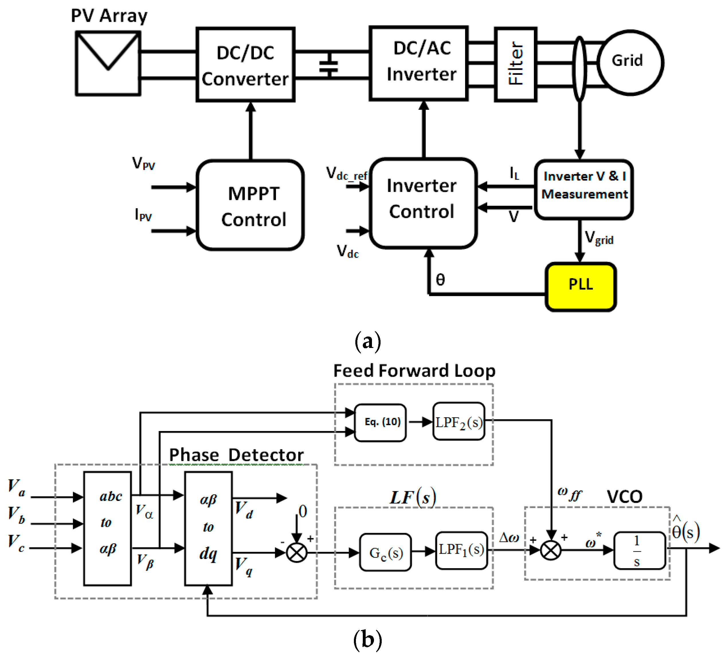
The basic block diagram of the grid-connected photovoltaic system is shown in Figure 1a. The solar photovoltaic system is connected to the gird through a DC/DC converter and an IGBT-based inverter. To synchronize the inverter with a grid, the phase-locked loop plays a major role in the inverter control. Generally, a basic synchronous reference frame based phase-locked loop is used. The basic SRF phase-locked loop tracks the input signal phase and frequency using the closed-loop feedback control loop.
The phase detector generates an error signal with reference to the difference between input and feedback signal, and the loop filter is generally a PI controller that filters the error signal. The center frequency of VCO is fixed at a nominal frequency (feed-forward constant), and the function of the VCO is to generate a signal of frequency (Δω) at the point when the input frequency veers off from the nominal frequency. When a supply frequency has a significant deviation from the nominal value, the locking time increases considerably. Since ∆ω << ωff, if ωff is updated as a function of the supply frequency, the frequency error is easily eliminated, and the loop filter can reduce only the phase error, which reduces the response time of PLL.
As shown in Figure 1b, in addition to the feedback loop, the feed-forward frequency PLL (FPLL) consists of a feed-forward loop. The center frequency of the VCO is dynamically adjusted by the feed-forward loop, and thus the center frequency of the VCO varies under frequency deviations, and the correction to be made by the feedback loop decreases. Therefore, this control technique increases the dynamic efficiency of the PLL under a significant variation in input frequency from the nominal value.
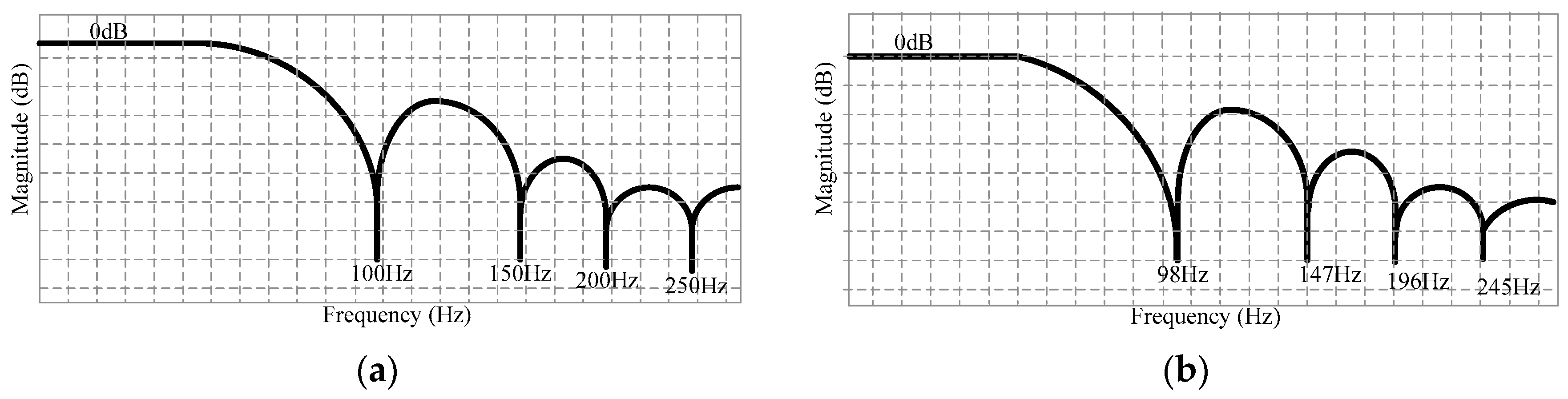
A filter is used to create an undistorted output along with the PI controller even under uncertain utility scenarios, namely phase shift, unbalance, and harmonics. In FPLL, a moveable average filter is used to removes the numerous frequencies ripple due to distorted utility conditions. The moving average filter (MAF) having the capability of eliminating any ripple, which is multiple of its intended frequency. Therefore, the harmonics and double frequency ripples are easily canceled out by using MAF. The frequency-dependent attenuation characteristics are exhibited, which is considered as the major problem with MAF. The ripples due to disturbances change while the changes in supply frequency. In such cases, the disturbance components are not completely blocked by the MAF, and PLL reveals spoor results.
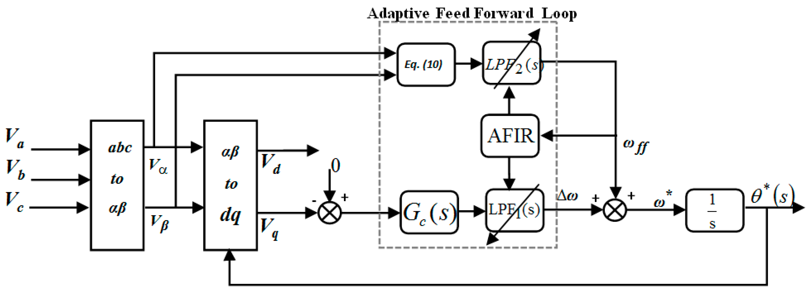
To improve the filtering characteristics, an adaptive frequency moving average filter is essential. Figure 2 illustrates the structure of adaptive FPLL for grid synchronization.
To design a frequency-adaptive moving average filter, several methods [24,25] have been proposed. The adaptive MAF can be obtained either by modifying the filter order with respect to the grid frequency fluctuation, or by adjusting the sampling frequency for the phase-locked loop with respect to the supply frequency, or by using the FIR coefficient in the form of a lookup table. In the proposed work, the coefficient of the Adaptive FIR (AFIR) filter is modified by using a lookup table. The lookup table provides frequency coefficients varying from 20 to 60 Hz for input supply. The frequency spectrum is broken down into 14 bands with each 3 Hz band. On that basis, the adaptive MAF filter automatically updates the filter coefficient, which enables the ripples to be diminished under distorted conditions.

3. Small Signal Modeling

The design of FPLL’s small-signal modeling is presented in this section. Va, Vb, and Vc are the magnitude of the three-phase voltage.
[ V a V b V c ] = [ V m cos θ V m cos ( θ 2 π / 3 ) V m cos ( θ + 2 π / 3 ) ]
The transformation of these signals into the stationary reference frame signals Vα and Vβ are done by Clarke transformation, and Park transformation is used for transforming to dq frame.
[ V α V β ] = 2 / 3 [ 1 1 / 2 1 / 2 0 3 / 2 3 / 2 ] [ V a V b V c ]
[ V d V q ] = [ cos θ * sin θ * sin θ * cos θ * ] [ V α V β ] = V [ cos ( Δ θ ) sin ( Δ θ ) ]
where,
Δ θ = θ * θ
and V is the magnitude.
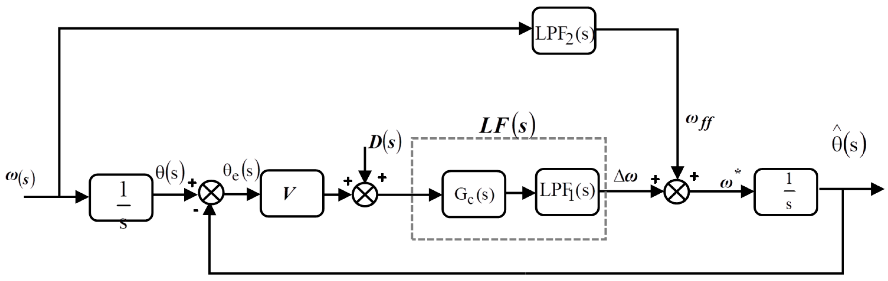
Figure 3 shows the small-signal model of FPLL, where LPF(s) represents the first order low pass filter, LF(s) represent the transfer function of the loop filter, ∆ω represents the change in frequency from the nominal value of frequency in rad/s, D(s) represents the disturbance in the input signal, ωff and ω* are the feed-forward frequency, AFIR represents the Adaptive Finite Impulse Response filter and the estimated frequency. The θe(s), θ(s), and θ^(s) are the phase angle error, input angle, and estimated angle, respectively.
The low pass filter LPF1 is given by
LPF 1 ( s ) = ω p / ( s + ω p )
A PI controller is connected to the low pass filter whose transfer function is given by
G c ( s ) = ( K p + K I / s )
From (5) and (6), the loop filter of FPLL is derived as
LF ( s ) = K P ω p s + K I ω p s ( s + ω p )
The FPLL’s open-loop transfer function is defined as
G ol ( s ) = ( ω p s 2 + K p V ω p s + K i V ω p s 3 )
The FPLL feed-forward frequency is
ω f f ( s ) = LPF 2 ( s )   ω ( s ) ,
where,
ω ( s ) = L ( d { tan 1 ( V β ( t ) / V α ( t ) ) } dt )
L is the Laplace operator. In addition, any change in ∆ω update the value of ωff, and the frequency error is removed rapidly under wide frequency deviations. Therefore, the PI controller minimizes the error and therefore the monitoring time is reduced considerably.

4. Performance Analysis of FPLL

The performance and stability analysis is carried out under wide variation in change in frequency and input voltage magnitude. To analyze the stability, the input voltage magnitude is varied from 1 p.u. to 0 p.u. From (6), the FPLL characteristics polynomial is given by
s 3 + ω p s 2 + V K P ω p s + V K I ω p = 0
Stability requirements for Routh–Hurwitz refer to the characteristic polynomial equation of the FPLL and the stability conditions are derived as
ω p > 0 K I > 0 V > 0 τ i > τ f }

4.1. Evaluation of System Performance under Voltage Sag

The error transfer function (i.e., θ e ( s ) / θ ( s ) ) of FPLL is obtained from the small-signal model is
G e ( s ) = θ e ( s ) θ ( s ) = s 3 s 3 + c n 2 s 2 + Vc n 1 s + Vc n 0
The denominator polynomial is compared to the third order under the damped system in Equation (12).
( s + a ) ( s 2 + 2 ξ ω n s + ω n 2 )
where ω n —natural frequency of oscillation and ξ is the damping ratio.
The under-damped third-order system roots are determined by the following PLL parameters
a 3 a 2 cn 2 + aVcn 1 Vcn 0 = 0
The value of the natural oscillation frequency ω n is identified by taking positive real root,
ω n = Vcn 0 a
The damping ratio ( ξ ) of FPLL is determined by
ξ F P L L = c n 2 a 2 ω n
θ e ( t ) = K 1 e at + K 2 e ζ ω n t cos ( ω d + θ )
The Equation (17) indicates that error in theta, where theta is depends on the real pole (a) and complex pole (ξωn). The ramp reduction of input voltage magnitude results in the raise of the magnitude of ‘a’ and reduction in the magnitude of ξωn. Table 1 shows the change overshoot and damping ratio for variation in input voltage. Figure 4a shows the change in the magnitude of input voltage, which results in a decrease in the transient response of the system due to an increase in magnitude (‘a’). For different bandwidths, the settling time of FPLLs, increase gradually and remain stable. Figure 4b shows the theta error for a step-change in frequency, from Figure 4b, it is observed that the increase in damping ratio reduces the transients of proposed FPLL with fewer steady-state errors when compared to the conventional system.

4.2. Adaptive Feed-Forward Phase-Locked Loop

In the earlier analysis of the method presented in [20], the FIR filter was considered as a first-order low pass filter to verify the stability of PLL. In this section, the filtering characteristic of the FIR filter is analyzed under a wide variation in input voltage. If any voltage unbalances occur at a nominal frequency, then a ripple of double the fundamental frequency appears in the qd axis. These ripples result in the erroneous estimation of ‘θ’. However, a low pass filter is used to filter out the ripples, the response time of the system increases. To overcome that, a linear phase FIR filter is added to FPLL, which provides high attenuation to multiple fundamental frequency components.
It is observed that, apart from increasing the dynamic performance of the system, the FIR filter attenuation factor is high during the presence of multiple of the fundamental frequency. However, in FPLL, the FIR filter is designed to operate for a fixed frequency of 50 Hz [20]. This filter effectively eliminates the double frequency ripples under distorted conditions. When the supply frequency deviates from the nominal value, the frequency of the ripples (due to distortions in the grid) also varies with the supply frequency. Hence a filter designed for nominal frequency shows poor performance under frequency variation. In order to overcome this problem, an adaptive FIR filter which updates its parameters for change in supply frequency is proposed. Figure 2 shows the block diagram of the FPLL with an adaptive FIR filter. The FIR filter is designed to remove the distortions in the rotating frame and generate a pure sinusoidal reference signal. It provides a high attenuation during any variation in supply frequency. To solve this problem, an FIR adaptive filter needs this updates its parameter with reference to the change in frequency. The proposed PLL, with an adaptive feed-forward FIR filter, is shown in Figure 2. In this proposed work, the FIR filter coefficient is modified by using a lookup table. The filter coefficients for the frequency range of 20 to 60 Hz are pre-loaded in the lookup table. The frequency variation is divided into 14 bands, which have a 3 Hz bandwidth. Reduction of bandwidth can boost the precision, and it increases the computational burden of adaptive filters. Therefore a bandwidth of 3 Hz is selected with sufficient accuracy. For every change of 3 Hz, the coefficient of the FIR filter is updated with new values from the pre-loaded lookup table. Hence, the adaptive FIR filter updates the coefficients within the specified band, which results in enhanced filtering characteristics under distorted conditions. The filtering characteristics of PLLs are presented in Figure 5 to show effectiveness.
Figure 5a shows the bode magnitude of FPLL in which the filter provides high attenuation at 50, 100, and 300 Hz. The ripple frequency varies with supply frequency if the utility frequency changes. From Figure 5b, it is notable that the Adaptive FIR filter provides high attenuation under frequency variation. When the frequency changes from 50 to 49 Hz, the ripple frequency also changes to multiple of the fundamental frequency, i.e., 98, 147 Hz, etc. it updates the loop filter parameter automatically based on input frequency, which enables to filter out the multiples of the fundamental frequency.

5. Results and Discussion

The simulation of the proposed frequency adaptive feed-forward PLL is simulated using MATLAB/Simulink, and the laboratory prototype is developed for a 3-ϕ, 415 V, 50 Hz source using an Altera Cyclone II field-programmable gate array (FPGA) board. In addition, the laboratory prototype of FPLL is developed to assess the results obtained using the simulation. The developed prototype is shown in Figure 6.
For the development of a prototype, a three-phase IGBT based inverter is built using Semikron Modules. The IGBT is driven by the Semikron SKHI22A gate driver circuit with the switching frequency of 20 kHz. To measure the voltage and current of the inverter and grid, LV25P voltage transducer and LA55P current transducer are used. The control algorithm is digitally implemented using the Altera Cyclone II FPGA board. The grid voltage is adjusted using 3 phase autotransformer to set the required grid voltage. The computer and FPGA board are connected via a USB port to dump the program. To verify the effectiveness of the PLL, the correlation was made between the performance of traditional synchronous reference frame PLL with the performance of proposed adaptive FPLL under phase angle tracking and the wide variation in nominal frequency under abnormal grid conditions such as frequency variance imbalance, phase jump due to addition inductive or capacitive load, harmonics and the relevant results are presented here.
The proposed FPLL implemented using a simulation environment has been implemented, and results were obtained under various conditions such as (i) frequency deviation, (ii) phase jump, (iii) harmonics, (iv) unbalance condition. Similarly, the same conditions were incorporated in the developed prototype, and a result obtained via the developed prototype is compared with the simulation studies and other conventional techniques.

5.1. Frequency Deviation

To verify the effectiveness of the PLLs, the system is verified under a dynamic change in input frequency. The input voltage is maintained as constant, and at time t = 0.2 s a step change in frequency is applied to both proposed and conventional systems. The step frequency response of the traditional synchronous reference frame PLL and the proposed adaptive feed-forward PLL for ramp frequency change is shown in Figure 7. 
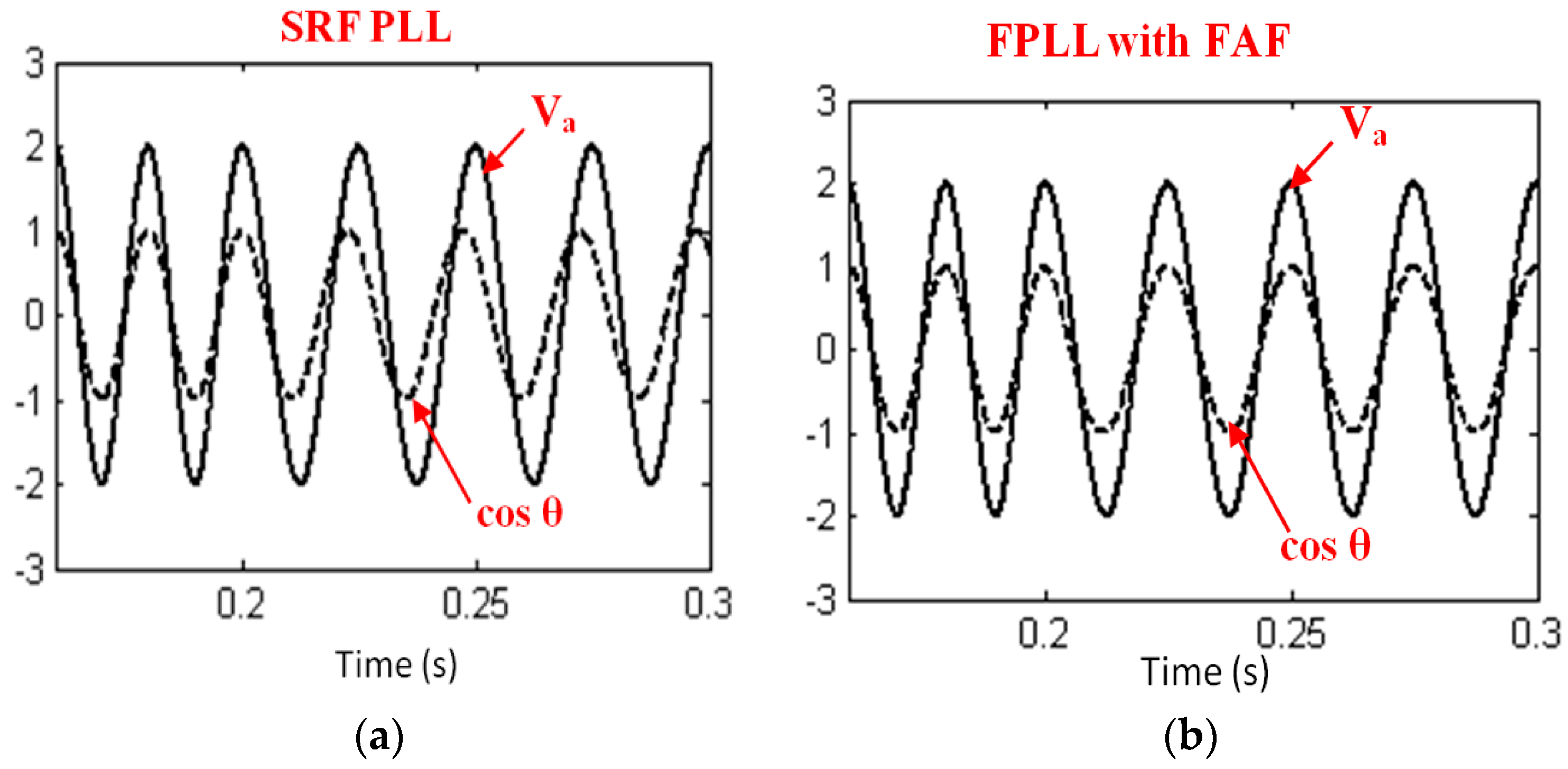
Figure 7 shows that the input supply frequency is initially 50 Hz. Both SRF and FPLL signals are in phase with the input signal. At time t = 0.2 s, the step-change in input frequency from 50 to 40 Hz occurs for both SRF and FPLL, and the results (Figure 7a) that SRF PLL exhibits poor performance under frequency deviations when the supply frequency is reduced from 50 to 40 Hz. The SRF PLL is unable to decrease phase and frequency error to zero. This results in a phase lag between the voltage being applied and output theta of PLL. To eliminate the frequency error in FPLL, the gain of the frequency adaptive filter is dynamically varied with the help of a feed-forward frequency loop. The FPLL output is always synchronized with the input signal irrespective of the input frequency deviation from nominal frequency, which is clearly illustrated from Figure 7b.
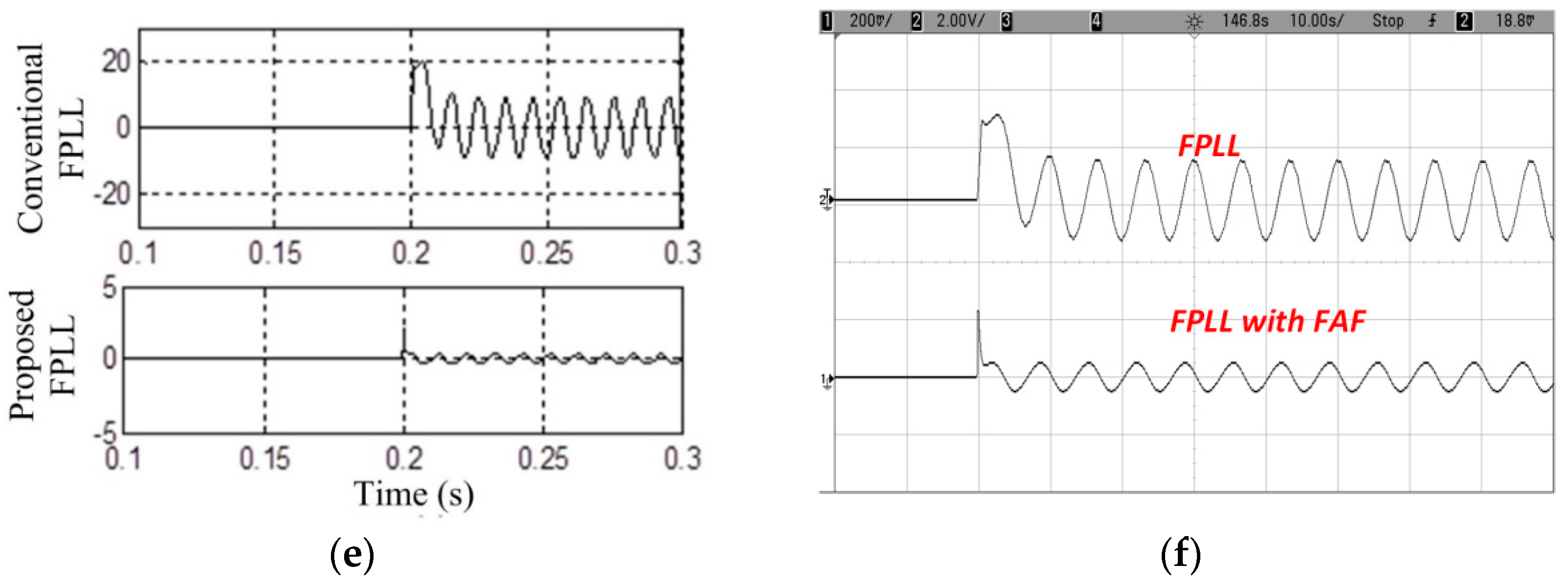
The performance of SRF PLL and the proposed adaptive feed-forward PLL under a wide change in frequency is depicted in Figure 8. From Figure 8, it is observed that SRF PLL performance is unsatisfactory due to constant feed-forward frequency whereas, in FPLL with adaptive filter, there is a dynamical change in the feed-forward frequency due to the deviations in the supply frequency which quickly eliminates the frequency error. This helps to improve the dynamic response of the FPLL.
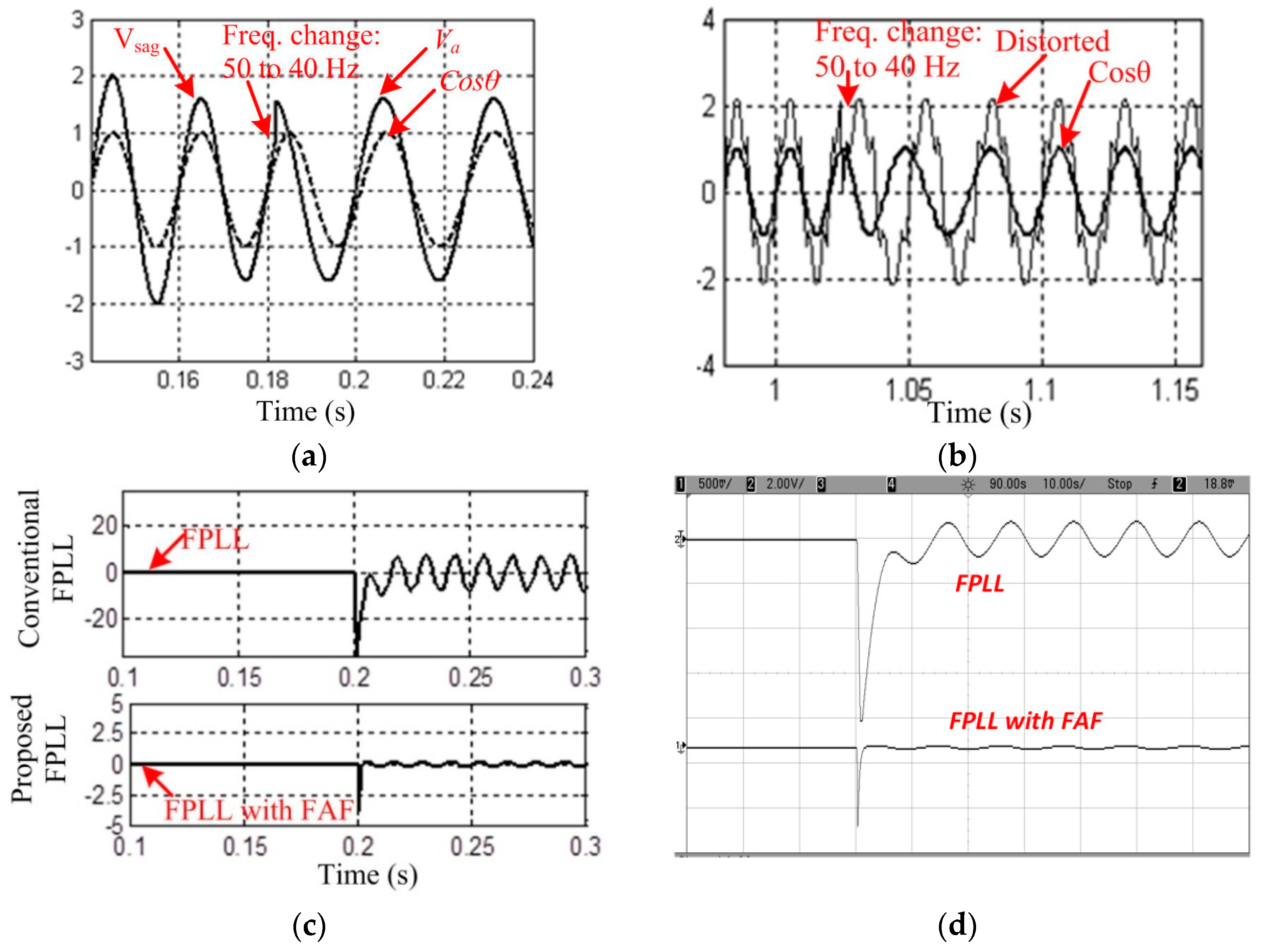
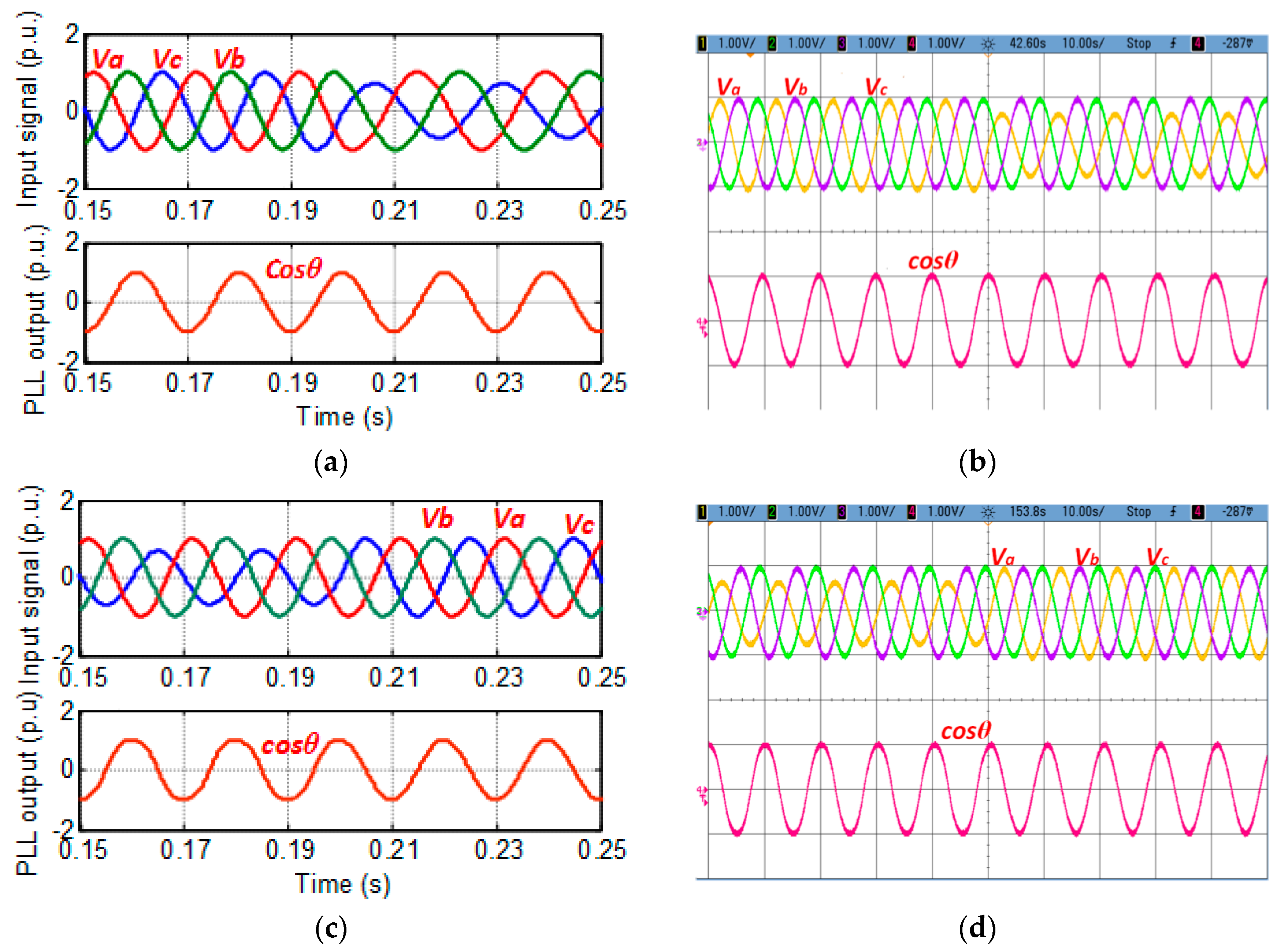
Figure 9 shows the performance of the proposed PLL under ramp change in frequency. To evaluate the performance of the PLL’s under distorted supply with ramp change in frequency, the phase voltage is reduced to 0.7Va at time t = 0.16 s (Figure 9a) and at t = 0.18 s the supply frequency is reduced to 40 Hz. Figure 9a shows the output proposed PLL where the output theta locks the utility within 0.04 s. The performance of the FPLL with a highly distorted input signal is depicting in Figure 9b. In this condition also the input signal in 0.04 s is tracked by the FPLL with a frequency adaptive filter.
Figure 9c shows the phase error simulation response for ramp change in supply frequency from 50 to 40 Hz at t = 0.2 s and Figure 9d illustrates the experimental results for ramp change in frequency. In FPLL, when the frequency changes from 50 to 40 Hz, the Vq component show ripples with a high magnitude, which is illustrated clearly in Figure 9c. In FPLL with a frequency adaptive filter, the steady-state error is reduced to negligible value. This has been verified experimentally and is shown in Figure 9d. To verify the performance under highly distorted conditions, the supply frequency is increased to 40 Hz from 50 Hz at time t = 0.2 s. As seen from the results shown in Figure 9e and Figure 9f, the presence of frequency adaptive filter has considerably increased the FPLL performance by reducing the theta error.

5.2. Phase Jump

The phase jump is the second condition, which is considered to show the effectiveness of the proposed PLL. In this condition, the sudden turning ON/OFF of inductive/capacitive load or a fault in the grid creates a change in phase of the load terminal voltage. To verify the effectiveness of the FPLL with a frequency adaptive filter under this situation, a phase shift of 30° is created with a 30% voltage sag is applied to the ‘A’ phase at time of t = 0.5 s. The simulation and experimental response of the adaptive FPLL (Figure 10a,b) illustrates the effectiveness of the proposed PLL under phase jump. FPLL with frequency adaptive filter locks to input supply and results in an undistorted synchronization signal (cosθ) is formed, which can be observed from the waveforms.
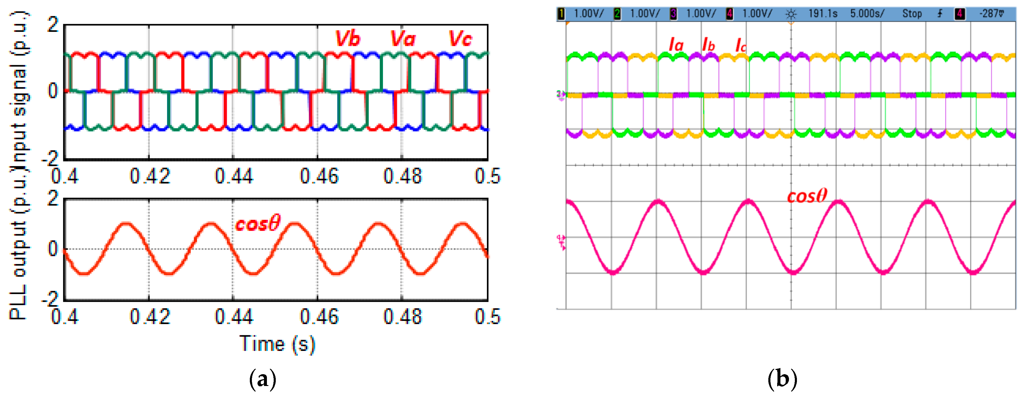
5.3. Harmonics

The performance of FPLL with a frequency adaptive filter with harmonic input is tested by measuring the input current of a 3-ϕ uncontrolled diode bridge rectifier. Because of the presence of multiple of the fundamental frequency (5th and 7th order) in the input signal, the qd axes have a ripple of 300 Hz. The occurrence of 300 Hz in qd axis is highly attenuated by FPLL with a frequency adaptive filter, and the system performance is shown in Figure 11a,b.

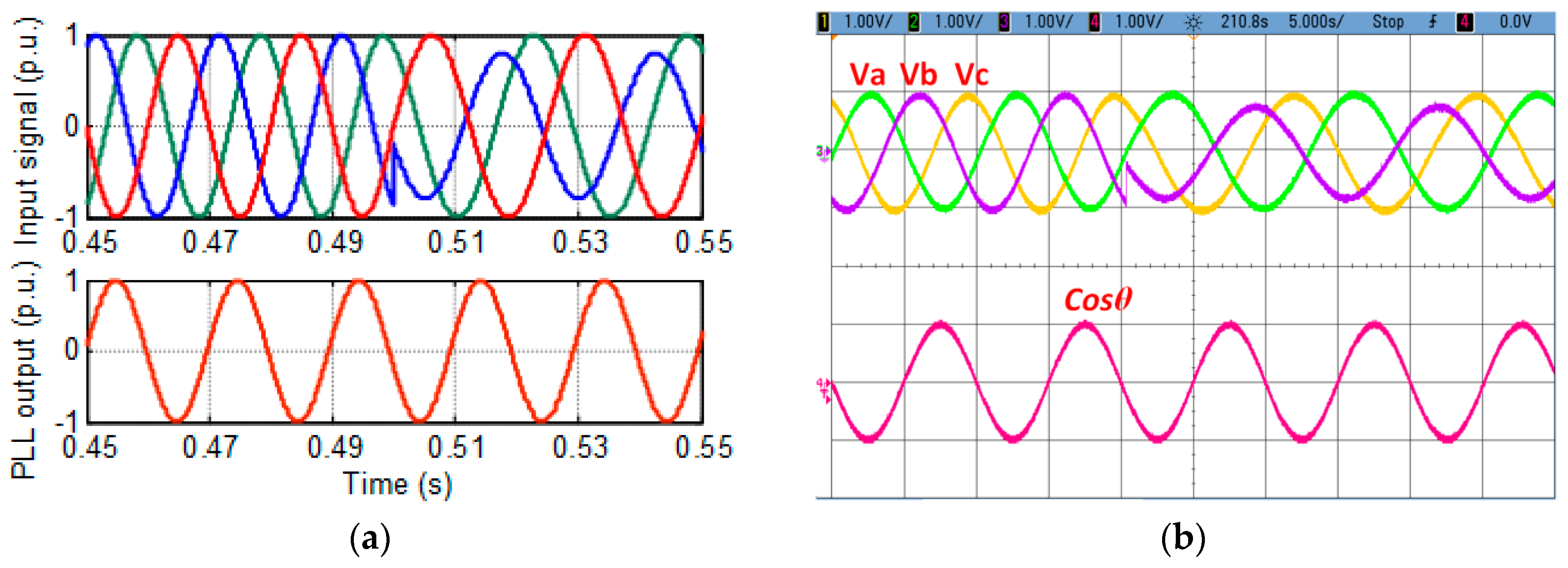
5.4. Unbalance Condition

To identify the effectiveness of the system, the FPLL with frequency adaptive filter is tested under voltage unbalance condition. For instance, the system is allowed to be in balanced condition and at t = 0.2 s, a sag in voltage of 30% is applied to phase ‘A’. The FPLL with a frequency adaptive filter removes the double frequency ripple and provides a perfect theta under unbalance condition, as shown in Figure 12a. To verify the effectiveness, again, the input three-phase supply is allowed to be in unbalanced condition with a voltage of 30% to phase ‘A’ and at time t = 0.4 s, the three-phase supply is a change to balance condition as shown in Figure 12c. It is observed from the experimental waveforms in Figure 12b,d that the FPLL with an adaptive frequency filter is immune to an unbalance in the input voltage.

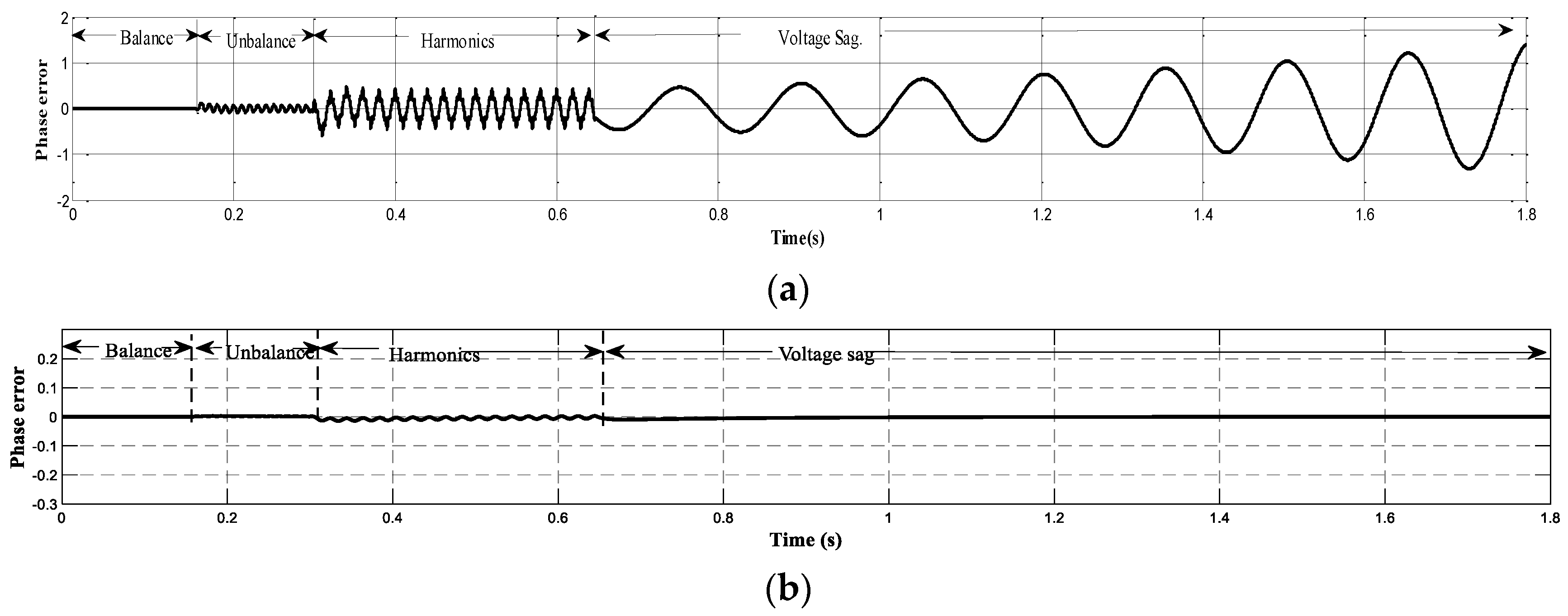
5.5. Performance Comparison of PLLs

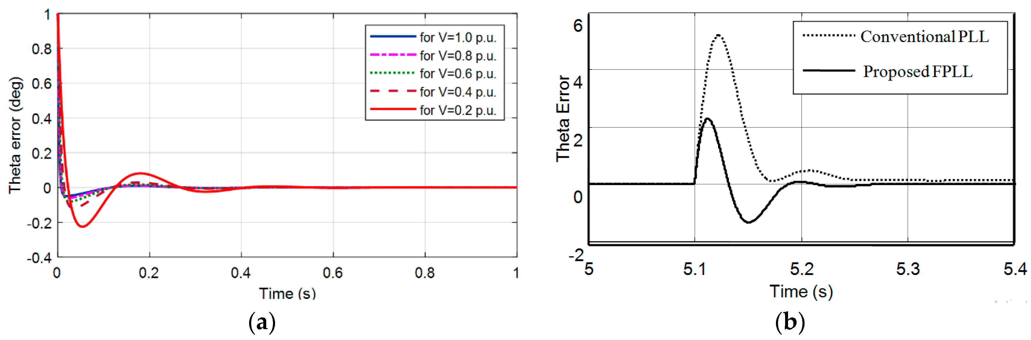
To show the effectiveness of the proposed PLL, a comparison has been made between the conventional and proposed adaptive feed-forward PLL and shown in Figure 13. The PLL’s performance is tested under different grid abnormalities such as unbalance, harmonics, voltage sag, and frequency deviations. From Figure 13b, it is observed that filtering characteristics of the proposed adaptive feed-forward PLL has improved when compared to the conventional PLL (Figure 13a). The proposed PLL is always stable under any change in voltage magnitude because the system is independent of voltage magnitude.

6. Conclusions

An adaptive PLL for tracking of the input signal of phase and frequency under wide frequency variations was presented in this paper. In the proposed system, the center frequency of the PLL is dynamically varied with respect to the supply using a feed-forward loop, which results in the improved dynamic response under wide frequency deviations. The detailed analysis of adaptive feed-forward PLL shows that this feed-forward loop not only improves the dynamic response but also it increases the stability region, and also it reduces the effect of voltage variation on the performance of the FPLL. The filtering characteristics are improved by employing a frequency adaptive filter which filters out the multiple frequency ripples caused by the distorted utility. Further, the proposed adaptive feed-forward loop provides a high attenuation to harmonics yields good filtering characteristics under grid imperfection. The comparison is made with the performance of the proposed PLL and that of the conventional PLL under various grid conditions, and the stability analysis is carried out. The simulation of the proposed frequency adaptive FPLL is simulated using MATLAB/Simulink, and the laboratory prototype is developed to test the PLLs in real-time using an Altera Cyclone II FPGA board. The results obtained for the various grid conditions, such as frequency variation, harmonics, imbalance, and phase shift, illustrate the good filtering characteristics and phase tracking capability of the proposed technique.

Author Contributions

A.C.K.: Conceptualization, Methodology, Software, Data curation, Formal analysis, Writing—Reviewing and Editing. J.P.: Software, Investigation, analysis, Writing—Reviewing and Editing, Supervision. A.S.: analysis, Writing—Reviewing and Editing. T.S.B.: Formal analysis, Visualization, Writing— Reviewing and Editing, Project Administration. M.R.I.: Reviewing and Editing, Project Administration. All authors have read and agreed to the published version of the manuscript.

Funding

This research received no external funding.

Conflicts of Interest

The authors declare no conflict of interest.

References

  1. Mastromauro, R. Grid Synchronization and Islanding Detection Methods for Single-Stage Photovoltaic Systems. Energies 2020, 13, 3382. [Google Scholar] [CrossRef]
  2. Liu, X.; Loh, P.C.; Wang, P.; Blaabjerg, F. A Direct Power Conversion Topology for Grid Integration of Hybrid AC/DC Energy Resources. IEEE Trans. Ind. Electron. 2013, 60, 5696–5707. [Google Scholar] [CrossRef]
  3. Behera, R.R.; Thakur, A.N. An overview of various grid synchronization techniques for single-phase grid integration of renewable distributed power generation systems. In Proceedings of the 2016 International Conference on Electrical, Electronics, and Optimization Techniques (ICEEOT), Chennai, India, 3–5 March 2016; pp. 2876–2880. [Google Scholar]
  4. Daniel, M.-G.; Omar, A.-M.; Rubén, T.-O.; Abel, G.-B. Comparison of Different PLL Strategies for Applications in a Wind Generation System. Procedia Technol. 2013, 7, 150–157. [Google Scholar] [CrossRef] [Green Version]
  5. Xia, T.; Zhang, X.; Tan, G.; Liu, Y. Synchronous reference frame single-phase phase-locked loop (PLL) algorithm based on half-cycle DFT. IET Power Electron. 2020, 13, 1893–1900. [Google Scholar] [CrossRef]
  6. Golestan, S.; Freijedo, F.D.; Vidal, A.; Guerrero, J.M.; Doval-Gandoy, J. A Quasi-Type-1 Phase-Locked Loop Structure. Lett. IEEE Trans. Power Electron. 2014, 29, 6264–6270. [Google Scholar] [CrossRef] [Green Version]
  7. Chung, S.-K. A phase tracking system for three phase utility interface inverters. IEEE Trans. Power Electron. 2000, 15, 431–438. [Google Scholar] [CrossRef] [Green Version]
  8. Zhou, G.; Shi, X.; Fu, C.; Wang, Y. Operation of a Three-phase Soft Phase Locked Loop Under Distorted Voltage Conditions Using Intelligent PI Controller. In Proceedings of the TENCON 2006-2006 IEEE Region 10 Conference, Hong Kong, China, 14–17 November 2006; pp. 1–4. [Google Scholar]
  9. Pal, K.; Kumar, S.; Singh, B.; Kandpal, T.C. Improved phase-locked loop-based control for grid-integrated PV system. IET Renew. Power Gener. 2020, 14, 705–712. [Google Scholar] [CrossRef]
  10. Wang, J.; Wang, J.; Luo, X. Novel PLL for power converters under unbalanced and distorted grid conditions. J. Eng. 2019, 17, 3895–3899. [Google Scholar] [CrossRef]
  11. Zhu, D.; Zhou, S.; Zou, X.; Kang, Y. Improved Design of PLL Controller for LCL-Type Grid-Connected Converter in Weak Grid. IEEE Trans. Power Electron. 2020, 35, 4715–4727. [Google Scholar] [CrossRef]
  12. Li, Y.; Wang, D.; Han, W.; Tan, S.; Guo, X. Performance Improvement of Quasi-Type-1 PLL by using a Complex Notch Filter. IEEE Access 2016, 4, 6272–6282. [Google Scholar] [CrossRef]
  13. Golestan, S.; Guerrero, J.M.; Abusorrah, A.M. MAF-PLL with Phase-Lead Compensator. IEEE Trans. Ind. Electron. 2015, 62, 3691–3695. [Google Scholar] [CrossRef] [Green Version]
  14. Wang, J.; Liang, J.; Gao, F.; Zhang, L.; Wang, Z. A Method to Improve the Dynamic Performance of Moving Average Filter-Based PLL. IEEE Trans. Power Electron. 2015, 30, 5978–5990. [Google Scholar] [CrossRef]
  15. Verma, A.K.; Jarial, R.K.; Rao, U.M. An Improved Pre-Filtered Three-Phase SRF-PLL for Rapid Detection of Grid Voltage Attributes. In Proceedings of the 2019 National Power Electronics Conference (NPEC), Tiruchirappalli, India, 13–15 December 2019; pp. 1–4. [Google Scholar]
  16. Rodriguez, P.; Lunar, A.; Teodorescu, R.; Iov, F.; Blaabjerg, F. Fault ride-through capability implementation in wind turbine converters using a decoupled double synchronous reference frame PLL. In Proceedings of the 2007 European Conference on Power Electronics and Applications, Aalborg, Denmark, 2–5 September 2007; pp. 1–10. [Google Scholar]
  17. Nos, O.V.; Abramushkina, E.E.; Kharitonov, S.A. Control Design of Fast Response PLL for FACTS Applications. In Proceedings of the 2019 International Ural Conference on Electrical Power Engineering (UralCon), Chelyabinsk, Russia, 1–3 October 2019; pp. 301–305. [Google Scholar]
  18. Han, Y.; Xu, L.; Khan, M.M. A novel synchronization scheme for grid-connected converters by using adaptive linear optimal filter based PLL (ALOF-PLL). Simul. Modeling Pract. Theory 2009, 17, 1299–1345. [Google Scholar] [CrossRef]
  19. Rosenkranz, W. Phase-Locked Loops with Limiter Phase Detectors in the Presence of Noise. IEEE Trans. Commun. 1982, 30, 2297–2304. [Google Scholar] [CrossRef]
  20. Rani, B.I.; Aravind, C.K.; SaravanaIlango, G.; Nagamani, C. A three phase PLL with a dynamic feed forward frequency estimator for synchronization of grid connected converters under wide frequency variations. Int. J. Electr. Power Energy Syst. 2012, 41, 63–70. [Google Scholar] [CrossRef]
  21. Liccardo, F.; Marino, P.; Raimondo, G. Robust and fast three phase PLL tracking system. IEEE Trans. Ind. Electron. 2011, 58, 221–231. [Google Scholar] [CrossRef]
  22. Golestan, S.; Ramezani, M.; Guerrero, J.M. An Analysis of the PLLs with Secondary Control Path. IEEE Trans. Ind. Electron. 2014, 61, 4824–4828. [Google Scholar] [CrossRef] [Green Version]
  23. Aravind, C.K.; Rani, B.I.; Manickam, C.; Guerrero, J.M.; Ganesan, S.I.; Nagamani, C. Performance Evaluation of Type-3 PLLs Under Wide Variation in Input Voltage and Frequency. IEEE J. Emerg. Sel. Top. Power Electron. 2017, 5, 971–981. [Google Scholar] [CrossRef] [Green Version]
  24. Luo, W.; Wei, D. A Frequency-Adaptive Improved Moving-Average-Filter-Based Quasi-Type-1 PLL for Adverse Grid Conditions. IEEE Access 2020, 8, 54145–54153. [Google Scholar] [CrossRef]
  25. Zeng, Z.; Yang, J.-Q. A grid synchronization method using frequency adaptive moving average filter. Zhejiang DaxueXuebao/J. Zhejiang Univ. 2014, 48, 1696–1703. [Google Scholar]
Figure 1. Grid-connected photovoltaic system (a) basic block diagram, (b) structure of phase-locked loop (PLL).
Sustainability 12 07048 g001
Figure 2. Structure of adaptive feed-forward frequency phase-locked loop (FPLL).
Sustainability 12 07048 g002
Figure 3. Small signal model of FPLL.
Sustainability 12 07048 g003
Figure 4. Theta Error (a) for a change in input voltage, (b) for step change in frequency.
Sustainability 12 07048 g004
Figure 5. Filtering characteristics of PLLs. (a) Conventional FPLL [20], (b) proposed adaptive feed-forward PLL.
Sustainability 12 07048 g005
Figure 6. Prototype of proposed PLL.
Sustainability 12 07048 g006
Figure 7. Response for frequency changeover from 50 to 40 Hz: (a) cos θ of SRF PLL, (b) cos θ of FPLL with frequency adaptive filter output.
Sustainability 12 07048 g007
Figure 8. Feed-forward frequency under frequency deviation.
Sustainability 12 07048 g008
Figure 9. Theta error for frequency during frequency change over from 50 to 40 Hz: (a) cos θ for voltage sag in ‘a’ phase, (b) cos θ for distorted input signal, (c) phase error under voltage sag-simulation results, and (d) phase error under voltage sag-experimental results, (e) phase error under highly distorted input-simulation results, (f) phase error under highly distorted input-experimental results.
Sustainability 12 07048 g009aSustainability 12 07048 g009b
Figure 10. The response of adaptive FPLL: (a) Simulation response under 30°, phase shift and (b) experimental results under 30° phase shift.
Sustainability 12 07048 g010
Figure 11. The response of adaptive FPLL under harmonic input: (a) Simulation response for 5th and 7th order harmonic input and (b) experimental results for 5th and 7th order harmonic input.
Sustainability 12 07048 g011
Figure 12. Response of PLL under unbalanced condition: (a) 3-φ balanced input to 3-φ unbalanced input (simulation), (b) 3-φ balanced input to 3-φ unbalanced input (experimental), (c) 3-φ unbalanced input to 3-φ balanced input (simulation), and (d) 3-φunbalanced input to 3-φbalanced input (experimental).
Sustainability 12 07048 g012
Figure 13. System phase error, (a) conventional PLL [20], (b) adaptive feed-forward PLL.
Sustainability 12 07048 g013
Table 1. Comparison between conventional and proposed FPLL.
SystemConventional
PLL
FPLLConventional
PLL
FPLLConventional
PLL
FPLLConventional
PLL
FPLL
Voltage1.p.u.0.5.p.u.0.23.p.u.0.2.p.i.
Closed loop Pole−28.52
−34 + j73.5
−34 − j73.5
−28.52
−34 + j73.5
−34 − j73.5
−25.49
−11.4−j59.5
−11.4 + j59.5
−48.81
−23.6 + j36.8
−23.6 − j36.8
−22.05
0.155−j36.8
0.155 + j36.8
−78.79
−8.98 + j21.6
−8.98 + j21.6
−21.43
1.01 + j41.6
1.01 + j41.6
−81.44
−7.66 + j20
−7.66 − j20
Damping ratio0.420.420.1890.5390.00350.385−0.02420.357
Overshoot23.323.554.613.498.92710830.1

