Article

Numerical Analysis of a Solar Tower Receiver Novel Design

by
Messaoud Hazmoune
1,2,*,
Benaoumeur Aour
1,
Xavier Chesneau
3,
Mohammed Debbache
2,
Dana-Alexandra Ciupageanu
4,
Gheorghe Lazaroiu
4,
Mohamed Mondji Hadjiat
2 and
Abderrahmane Hamidat
2
1
Département de Génie Mécanique, Laboratoire de Biomécanique Appliquée et Biomatériaux (LABAB), Ecole Nationale Polytechnique d’Oran—Maurice Audin, BP 1523 El Mnaour, Oran 31000, Algeria
2
Centre de Développement des Energies Renouvelables BP. 62 Route de l’Observatoire Bouzareah, Alger 16340, Algeria
3
LAboratoire de Mathématiques et PhySique, Université de Perpignan Via Domitia-Bât.B-2e étage, 52 avenue Paul Alduy, CEDEX 66860 Perpignan, France
4
Power Engineering Faculty, University POLITEHNICA of Bucharest, Splaiul Independenţei nr. 313, Sector 6, 060042 Bucharest, Romania
*
Author to whom correspondence should be addressed.
Sustainability 2020, 12(17), 6957; https://doi.org/10.3390/su12176957
Submission received: 5 August 2020 / Revised: 24 August 2020 / Accepted: 24 August 2020 / Published: 26 August 2020

Abstract

:
Efficient operation of thermal solar power plants is strongly dependent on the central receiver design. In particular, as the receiver tube determines the temperature behavior inside the receiver, its geometry proves to be the main factor affecting the solar tower receiver performances. This paper investigates the effect of several 3D geometric concepts on both temperature evolution and velocity of the working fluid at the receiver, in order to obtain an enhanced design, with augmented efficiency. A novel receiver tube with helical fins is proposed, aiming an increased heat exchange surface and improved thermal conduction. Extensive numerical simulation is carried out in ANSYS CFX (CFD) to assess the performances of the proposed solar tower receiver design. An unstructured mesh, generated by a computation machine, and (k-ε) turbulence model are employed to this regard. The results show that the tubes with helical fins for solar tower receivers give a very important increase in the outlet temperature, which can reach up to 1050 K.

1. Introduction

1.1. General Considerations

Thermal solar power rapidly gains interest during past decades, as a consequence of its higher energy conversion efficiency compared to other renewable energy technologies. For instance, if only focusing on the solar energy employment, it is emphasized that thermal solar power shows a demonstrated peak solar efficiency of 29% [1], while photovoltaic panels do not exceed 23% [2].
Within a thermal solar power plant, the solar receiver (which converts concentrated solar irradiation into thermal energy) represents one of the key components. Solar receivers using molten salt as heat transfer fluid are the most used, having successful applications in commercial plants (Figure 1) [3].
The solar receiver tube plays a very important role in increasing the efficiency of the solar tower producing thermal energy by converting solar energy into heat. Thus, many studies focus on improving the geometry of solar receivers to increase the thermal efficiency of the solar tower.

1.2. Literature Review

Garbrecht et al. [4] presented an innovative design of a molten salt solar receiver tower, consisting of numerous hexagonal pyramid elements arranged with their vertices pointing towards the heliostats. The thermal efficiency of this new receiver was evaluated based on CFD simulations is higher than that determined for existing concepts in the literature. The highest surface temperature predicted by the simulation is approximately 1070 K at the pyramidal base.
Pacio and Wetzel [5] conducted a study on the current state of liquid metal technology. They used (liquid sodium, PbBi alloy, and molten salt) to increase overall efficiency and reduce specific costs. This will require higher operating temperatures and higher heat flux densities. The results of an experimental study presented by Peipei Xu et al. [6] show that both water and wall temperature distribution are very unequal on the axial and radial directions. It has also been found that the thermal efficiency of the receiver tube increases with the input velocity.
In their work, Boerema et al. [7] studied the effect of different geometries on the resulting surface temperatures of tubular panel receptors. Four designs of tubular panels are examined in view of the sensitivity of these designs to high temperatures resulting from the modification of the heliostats network aiming point. They examined a single diameter tube receiver, an ideal flux receiver, a receiver using tubes of different diameters, and a receiver panel with tubes in series. Single and multiple diameter receptors exhibited high temperatures and high sensitivity under non-standard irradiation. They demonstrated that the large variation in HTF (Heat Transfer Fluid) output temperatures for the single-diameter receiver resulted in a high surface temperature with a maximum of 861 °C, while the multi-diameter receiver partially reduced surface temperatures. Pabst et al. [8] used a volumetric air receiver with a new material, so they performed two tests to show that the air outlet temperatures can reach up to 800 °C.
The influence of geometric internal surfaces also concerns a majority of research work. Deng et al. [9] proposed a model of heat transfer as a function of the angle factor. They developed the internal surface factor equations in the receiver with the finite difference method and an automatic mesh generation technique to solve the surface angle factor equations inside the receiver. Uhlig et al. [10] have tried to increase the size of the receiver in order to reduce the heat flux and thus the receiver temperatures, but this approach increases the specific costs of the receiver.
A new external receiver design, made of bayonet tubes, is proposed by Rodríguez-Sánchez et al. [11] to improve the thermal and mechanical behavior of the receiver during operation. The study proved that lower wall temperatures reduce receiver heat losses and enable an increased thermal efficiency by 2%. On the other hand, the lower temperatures of the film make it possible to use smaller tubes and to reduce the heliostats field. Colomer et al. [12] presented an advanced methodology for detailed modeling of heat transfer and fluid dynamics phenomena in solar tower receivers. The full model is composed of four sub-models (heat conduction, two-phase flow, thermal radiation, and natural convection). Montes et al. [13] proposed a new design for the surface of the active absorber of solar receivers for tower plants, dividing the flux into many circuits as quasi-symmetrical regions are defined on the surface of the absorber.
Sanchez-Gonzalez and Santana [14] presented, in 2015, a methodology to project the distribution of the flux from the mapping within the panels of the solar tower receiver. Thus, a computer code developed to model this methodology and the confrontation with SolTrace software has been successful, providing a new model that can provide a detailed thermal performance analysis and indicate effective ways to improve it. Qiu et al. [15] investigated heat loss reduction and parameter optimization. The results obtained report an outlet temperature of 572 °C with an air flow rate of 5 m3/h.
Badar et al. [16] studied the pressure losses issued by junction in a solar collector by means of modeling and simulation of a simplified collector junction in ANSYS Fluent. The results demonstrate that the losses depend on the flow rate, while the Reynolds number is low. Moreover, the proposed simulation model is able to predict the flow distribution for a multi-tube collector in a wide range of values for the Reynolds number. Liao and Faghri [17] proposed a new design of molten salt receiver of solar tower plant. This receiver is equipped with an evaporator series attached to the heat pipe. The evaporators added to decrease the molten salt freezing potential inside the receptor tube, thus extending the daily operating time of the receptor. The results show that the efficiency of the proposed design is 3% higher than the receptor Molten Salt Electrical Experiment cavity receiver. Maytorena and Hinojosa [18] presented a numerical study of a modified model of molten salt receiver that is based on the receiver model of Rensselaer Polytechnic Institute. This study fussed on the analyze of the creation of direct steam in a vertical tube. This model gave an increase in the mass of flow steam of 4.28 times with 44% of mass flux reduction. Montoya et al. [19] performed a finite element analysis of thin-walled tubes in a molten salt receptor. Their results proved that mechanical stresses play an important role in the distribution of the stress of the receptor tube. Moreover, they found that the stress component varying with respect to the mechanical boundary conditions is the axial stress. Therefore, the thermal stress of the tube has two components: one component of the internal stresses and another of the external stresses. It is highlighted that the last constraint is generated by the clips preventing thermal bending, which multiply about three times the equivalent stress. Wang et al. [20] investigated five new receptors with ailerons like design, aiming to improve the optical efficiency of the solar tower. It is noticeable that the proposed receptors are able to effectively decrease peak fluxes by more than 40% while reducing the optical efficiency by less than 1.1%. Kanatani et al. [21] developed a solar cavity receiver model using helical tubes for the heat absorber.

1.3. Aims of Research

According to the detailed literature review presented above, increasing the output temperature of the receiver is related to improving the heat transfer in the receiving tubes that is a key focus in the field of concentrated solar power. This paper presents a comparative numerical study of new receiver shapes, which aims to define the optimal receiver geometry that has the high heat transfer and high output temperature. The mathematical modeling concept are presented in Section 3 and all related quantities are listed in the Abbreviation. In addition, the temperature inside the receiver should not exceed the fusion temperature material of the receiver. To answer this problem, this research aims to increase the heat exchange surface and improve the heat conduction by proposing a helical finned receiver tube.
The proposed model is simulated in ANSYS CFX using molten salt (NaNO3-NaNO2-KNO3) with the heat transfer proprieties that are presented Table 1.

2. Proposed Receiver Tube Geometries

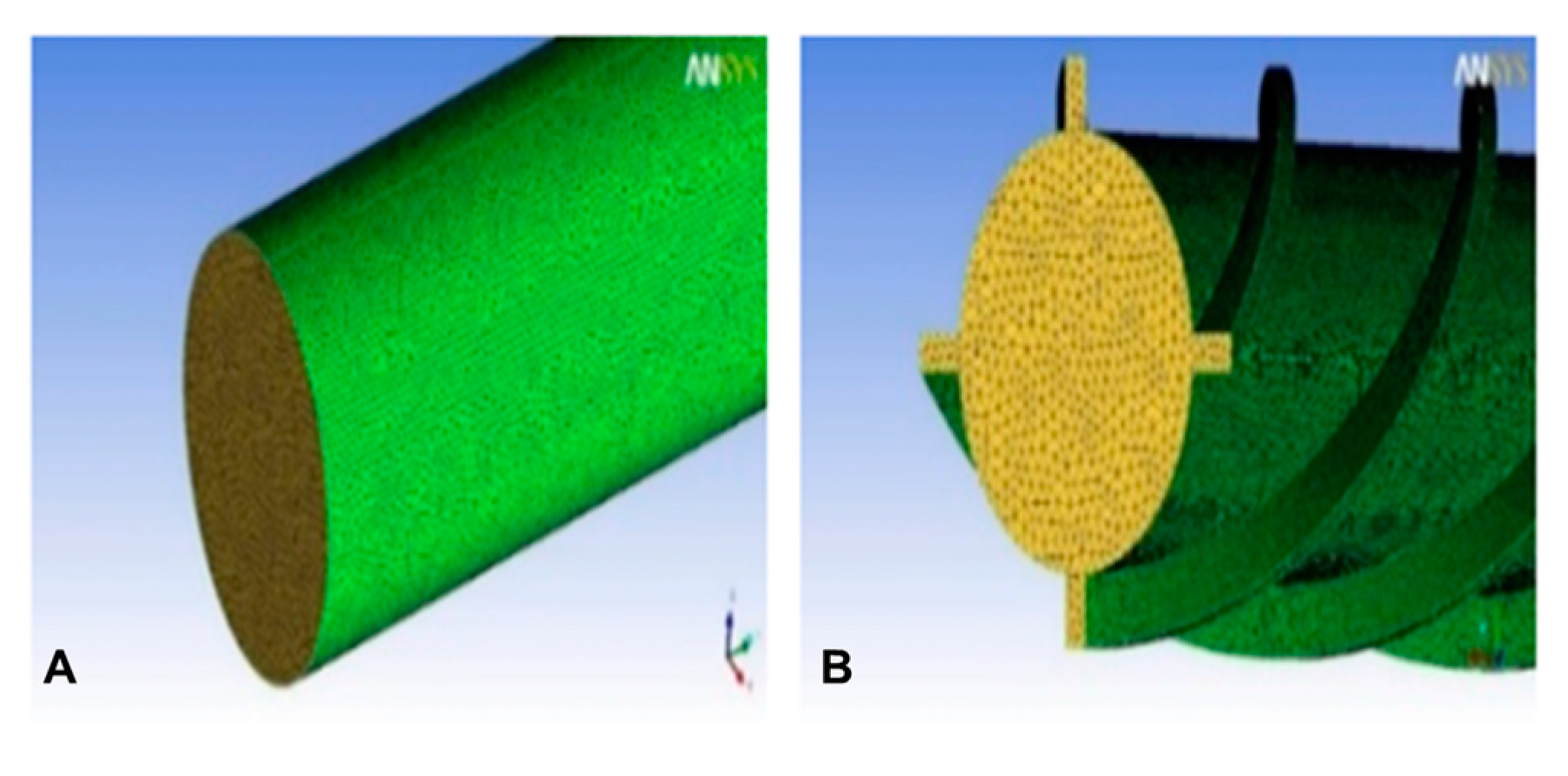
Figure 2 shows the proposed new design of the receiver tube in a solar tower. The internal geometry of the tube has two smooth shapes with helical fins, aiming to increase contact surfaces and heat exchange. The helical pitch has different values, as shown in Table 2, for the four configurations taken into account. The mesh is, therefore, modified accordingly, as represented in Figure 3 and Figure 4. Mesh adjustment is required in order to obtain a good compromise between the time of computation and a satisfactory precision.
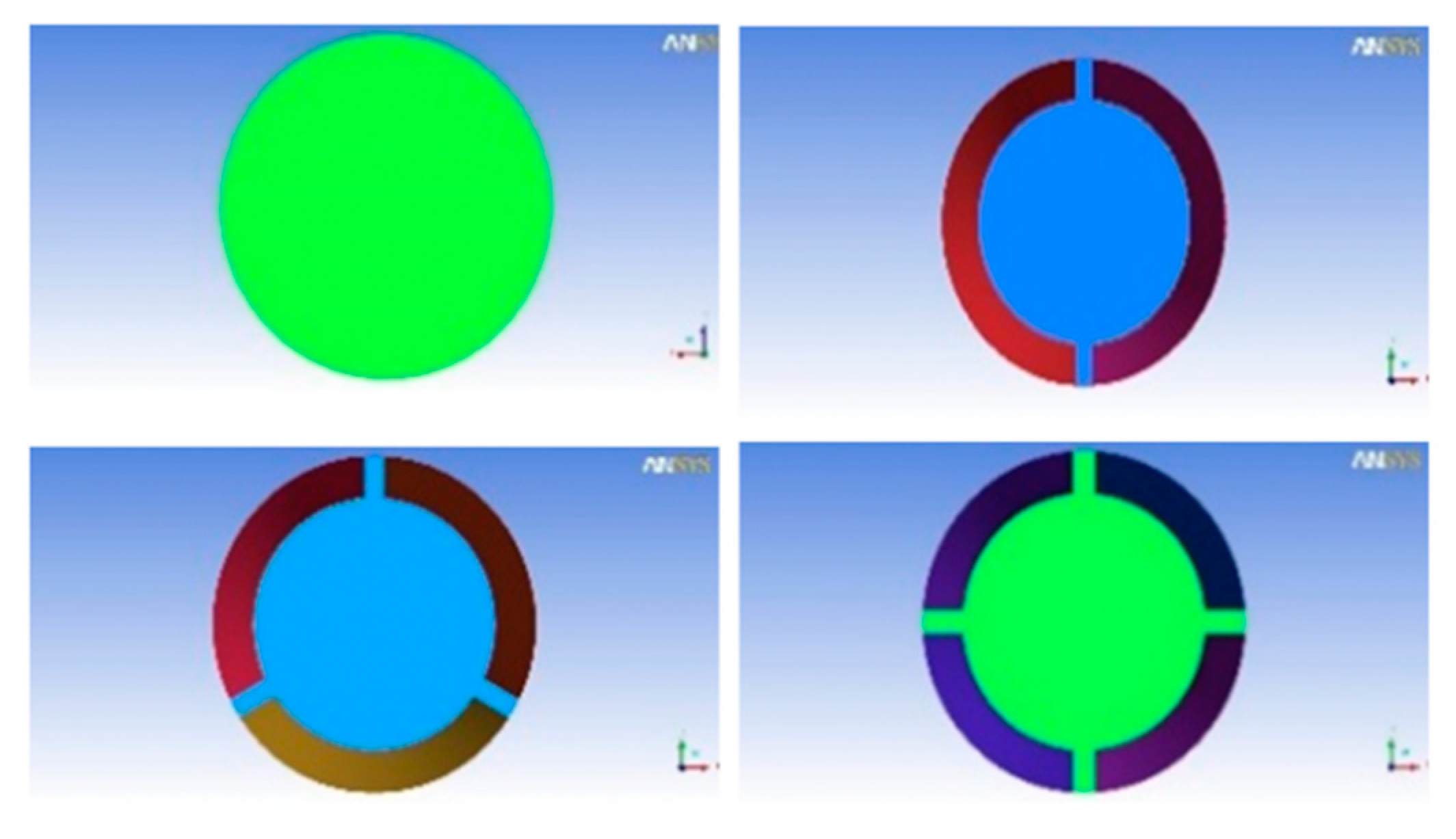
In order to study the effect of the fins, four cases examined using the new configuration having the greatest helical pitch length (400 mm), while also changing the number of fins as illustrated in Figure 4. The purpose of this study is to define the best geometric configuration with less complexity and a high heat transfer rate.

3. Mathematical Model

3.1. Conservation Equations

Continuity [23]:
u i ¯ x i = 0
Momentum [23]:
ρ u j ¯ u i ¯ x i = p ¯ x i + x i [ μ u i ¯ x i ρ u i u j ¯ ¯ ] + ρ g i
Energy [23]:
ρ u j ¯ T ¯ x i = 1 c p x i [ k T ¯ x i ρ c p T u j ¯ ¯ ]
where: ui—instant velocity fluctuation on x direction (m/s), x—system coordinate; ρ —density (kg/m3), p—pressure (Pa), μ —viscosity (kg/m · s), g—gravity (m/s2), T—mean temperature (K), cp—specific heat (J/kg · K).

3.2. Turbulence

Turbulent kinetic energy (kt) [23]:
ρ u j ¯ k t ¯ x t = x j [ ( μ + μ t σ k t ) k t ¯ x j ] + P k t + G k t + ρ ε t
Dissipation of the turbulent kinetic energy (εt) [23]:
ρ u j ε t x j = x j [ ( μ + μ t σ ε t ) ε t ¯ x j ] + c 1 ε t ε t k [ P k t + c 3 ε t G k t ] c 2 ε t ρ ε t 2 k t
ui—instant velocity fluctuation in x direction (m/s); x—system coordinate; rho—density (kg/m3); p—pressure (Pa); μ —viscosity (kg/m · s); g—gravity (m/s2); T—mean temperature (K); cp—specific heat (J/kg · K); σ ε t , σ k t —turbulent Prandtl number; c 3 ε t , c 2 ε t —coefficients constants; Gkt—Generation of turbulent kinetic energy due to the buoyancy force.

3.3. Boundary Conditions

Q = h ( T T a m b ) n
Smooth   tube :                   Q = h . s . ( T T a m b )
Tube   with   fins :       Q = h . p . d x . ( T T a m b )
Q —Heat flux; T T a m b —the fluid temperature difference; S—total surface area of the smooth tube; h—the coefficient of convective transfer (W.m−2.K−1); p—perimeter of the fin (exchange perimeter of the convective flux).

3.4. CFD Modeling

The independence of the mesh was obtained with the profiles of mean values of the liquid temperature (T). The results obtained at the exit of the tube is made for the boxes where it meshed by tetrahedral element for the flowing number of elements (225,122, 365,146, 514,454, 716,218, 832,256, 972,446, 1,021,456, and 1,242,122), where different meshes produce the same behavior. In addition, the average percentage difference was determined for the temperature (T) between the coarsest mesh (972,446 elements) and the finest mesh (1242,122 elements), the initial coarse mesh of 972,446 elements and the solution converged to residue 1.10−6. Initializing our stationary adaptation gateway with a coarse mesh allows fast calculations with low complexity.

4. Results and Discussions

The results obtained are validated against the ones presented in the study by Garbrecht et al. [4] (as detailed in below), who proposed a new design of a receiver of a molten salt solar tower. The new receiver consists of numerous hexagonal pyramid elements arranged with their vertices pointing towards the heliostats. The thermal efficiency of this new receiver is evaluated through CFD simulations and exceeds the values determined for existing concepts reported in the literature.
In order to compare the performances of a smooth tube and a finned tube of a solar tower receiver, in the following are presented the results concerning the influence of the fin and the influence of the pitch of the fin on the flow temperature and velocity at the receiver. The influence of the number of fins in each tube was also investigated in this research.
To quantify the heat transfer associated with the fin, the temperature distribution along the fin from an energy balance point of view must be evaluated first. To establish this balance, the following simplifying assumptions are considered [24]:
  • The flow is permanent and there is no internal heat dissipation.
  • The thermal conductivity of the fin, k, is constant.
  • The convective exchange coefficient, h, is uniform over the entire surface of the fin.

4.1. Influence of the Fin Pitch on the Temperature Evolution

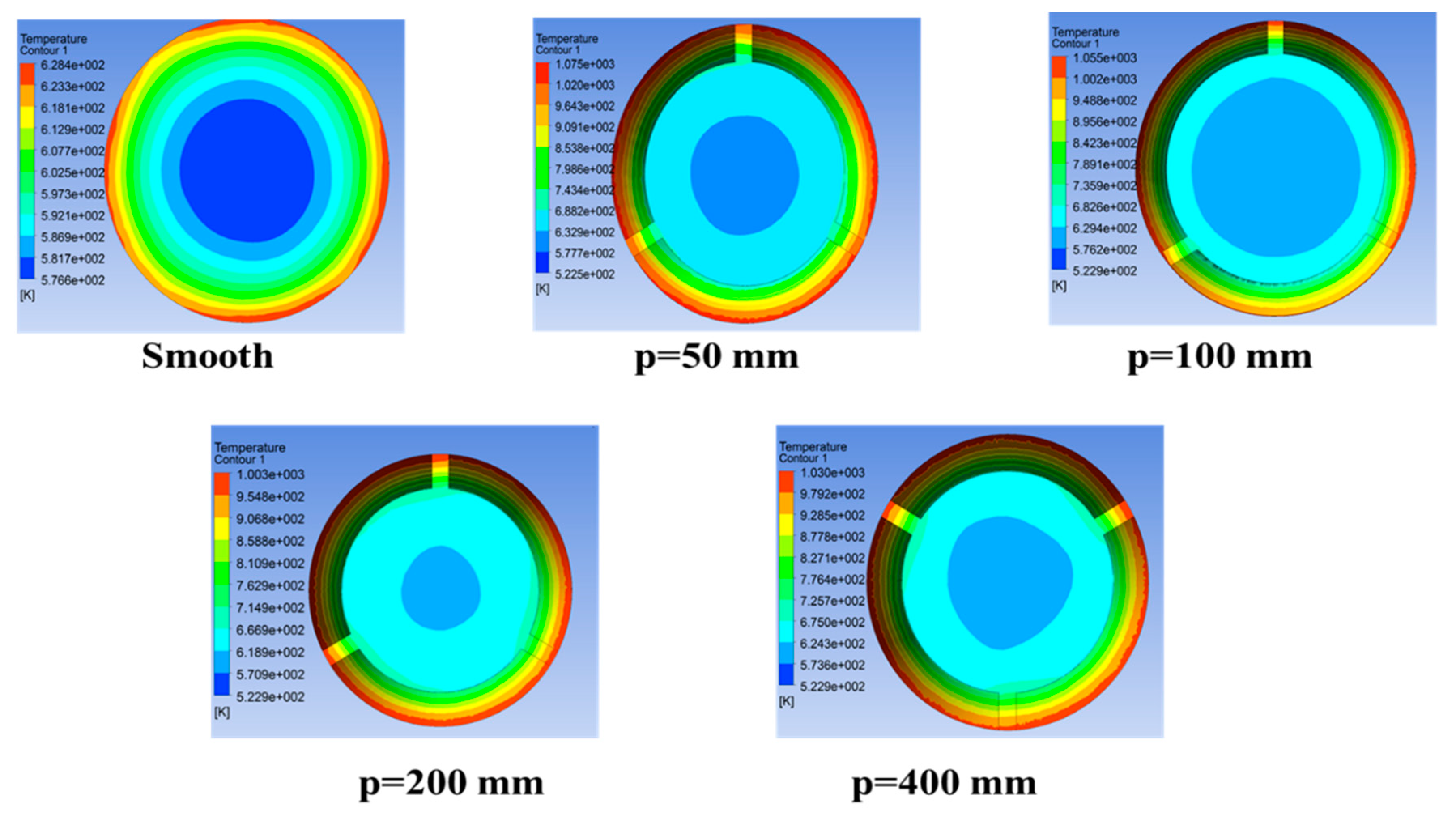
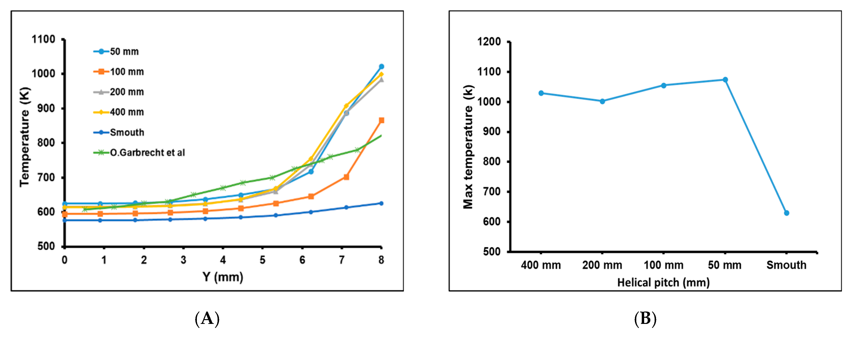
The fins are used to increase the heat flux transferred from the solid (tube walls) to the fluid. However, the fin itself owns a thermal resistance and adds it to the thermal circuit. From Figure 5 and Figure 6, it can be noted that the maximum temperature in the case where the tube is smooth reaches 629 K, while in the case of finned tubes, the temperature reaches very high values, even exceeding 1000 K. Therefore, a temperature difference of about 370 K emerges between the two types of tubes for a heat flow of 0.4 MW/m2. Indeed, the cylindrical tube provided with helical fin has a greater heat exchange surface than that available for a cylindrical tube having the same diameter, the same length, and the same boundary conditions, but without fin.
The influence of the fin pitch on the evolution of the temperature also studied in this research. To this aim, fins with different pitches (50, 100, 200, and 400 mm) are implemented. The results obtained show that the fin pitch has a significant influence on the heat transfer and the evolution of the temperature. As pictured in Figure 6, when the pitch is 50 mm, the maximum temperature reaches 1075 K, while for a pitch of 100 mm, the temperature is 1055 K. The maximum temperature decreases further with increasing the pitches to 200 and 400 mm, dropping to 1003 K. It is therefore highlighted that, to obtain higher temperatures, it is necessary to reduce the fin pitch. Moreover, it is evidenced that the fin presence can improve the heat transfer from the solid surface to the adjacent fluid. This is due to the fact that the fins improve the heat dissipation of a confined solid system in which the heat flux densities are high.

4.2. Influence of the Fin Pitch on the Velocity Profile

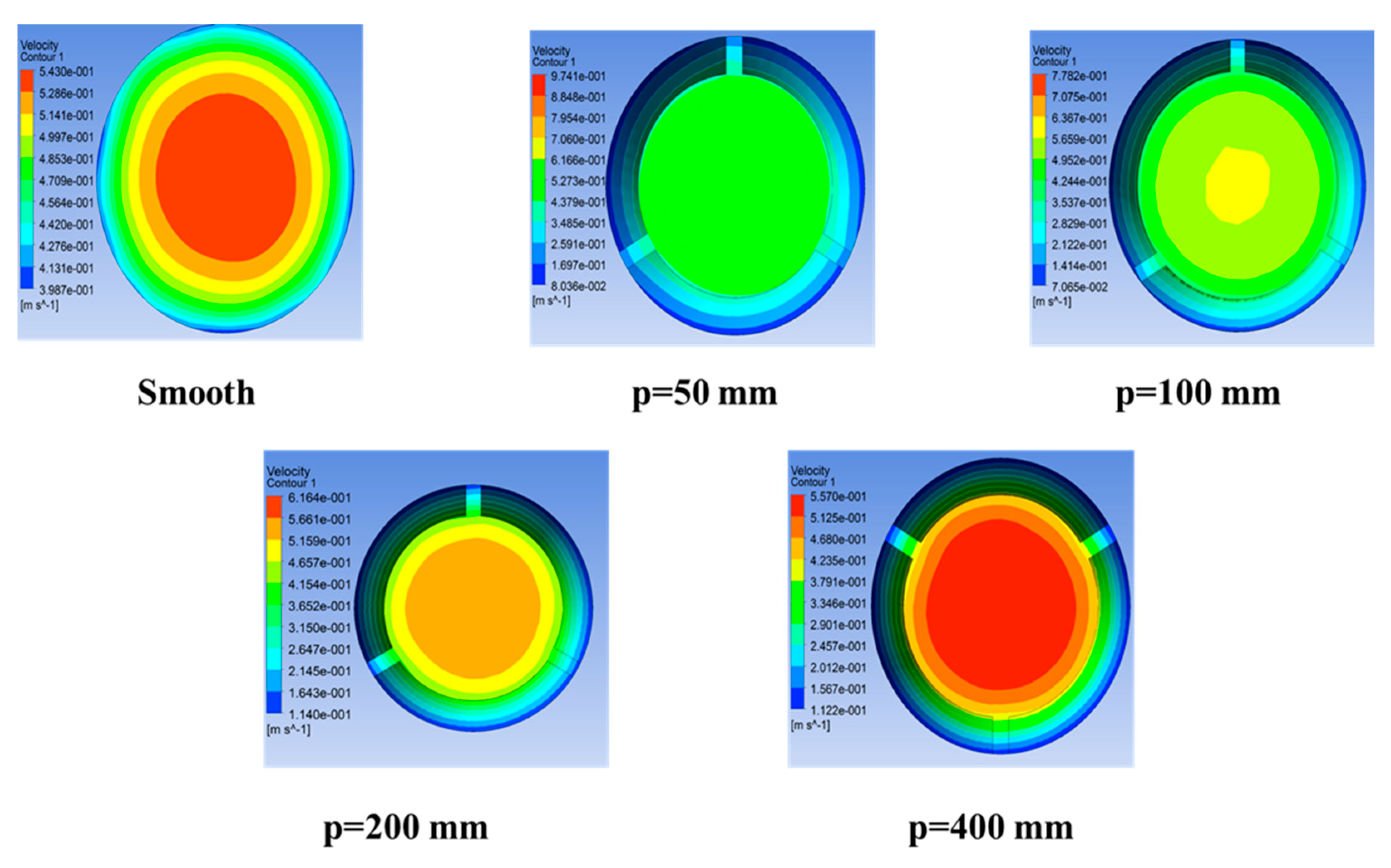
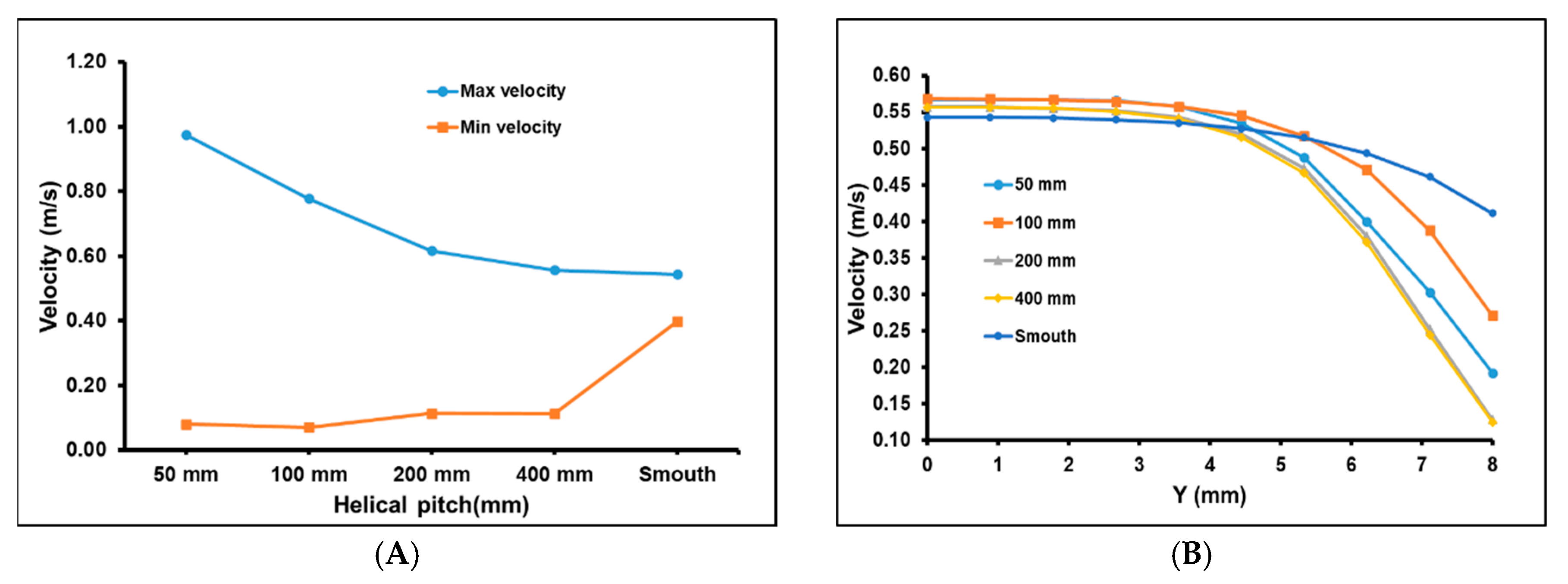
The flow velocity within the solar tower receivers plays a very important role since the fluid is the element enabling energy conversion (heat into mechanical energy). Figure 7 and Figure 8 depict the influence of the fin pitches (50, 100, 200, and 400 mm) on the coolant flow velocity.
It is remarked that, in the case of the smooth tube, the velocity varies from 0.39 to 0.54 m/s for an inlet of 0.5 m/s, so an increase of 0.04 m/s (8%) is acceptable. On the other hand, in the case of the finned tube, at the same inlet velocity of 0.5 m/s, the fin pitch directly influences the flow velocity, as shown in Figure 8. It is emphasized that, for the case of 100 and 50 mm, the velocity reaches up to 0.78 and 0.97 m/s, respectively. Simulation results show that increasing the fins pitches from 200 to 400 mm, the velocity varies within the ranges 0.12 to 0.56 m/s and 0.14 to 0.16 m/s, respectively, showing a slight decrease. Thus, a smaller fin pitch enables an increased flow velocity.
Overall, the results show that employing a helically shaped fin and decreasing the fin’s pitch allow obtaining a higher flow velocity of the fluid in the receiver. Since a very high mass flow rate is required to turn the turbine, the finned tube design remains among the optimal technological approaches.

4.3. Influence of the Number of Fins on the Evolution of the Temperature

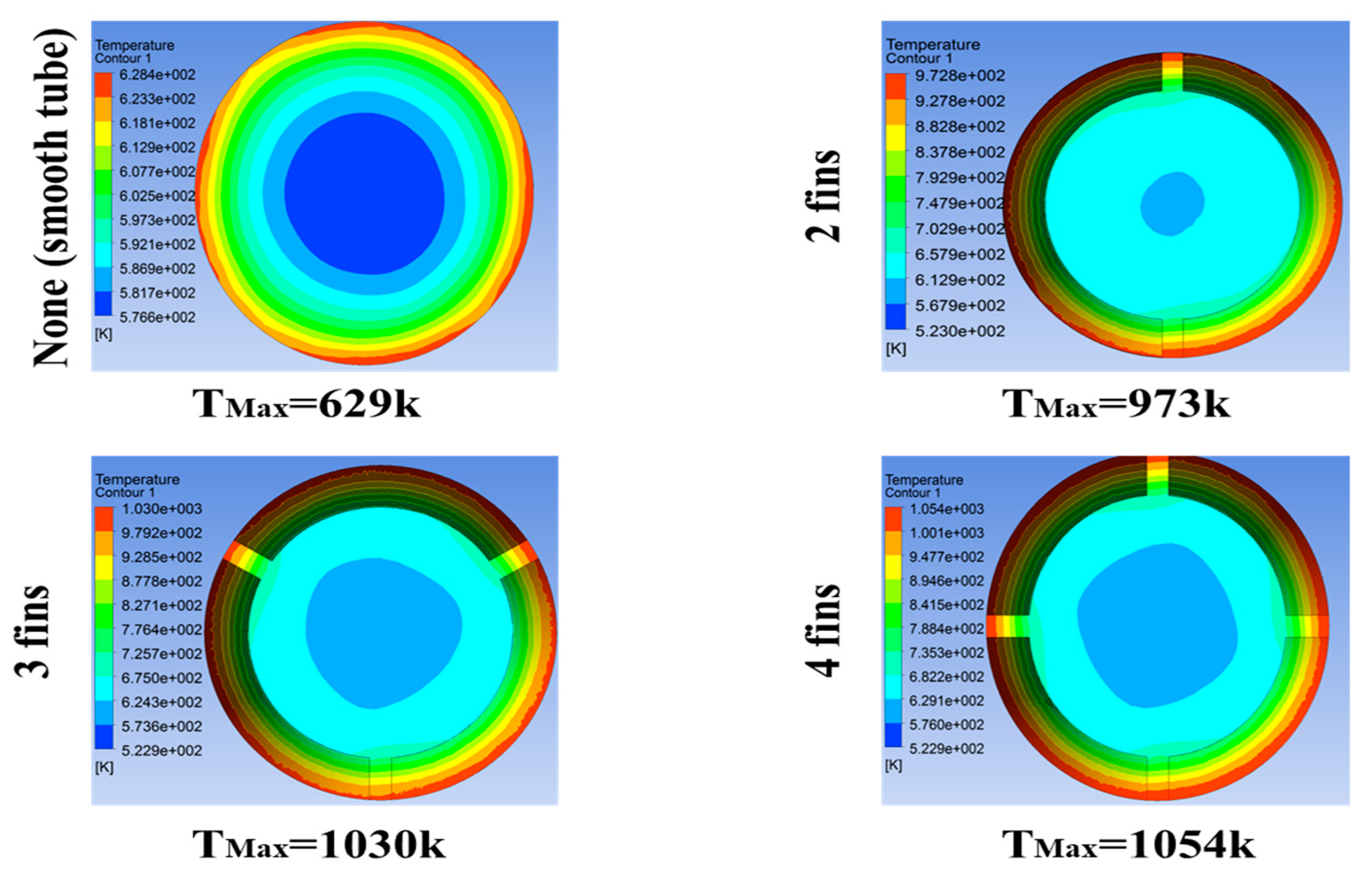
Increasing the heat exchange surface using the fins is one of the most popular passive methods to improve heat transfer, various studies proving that not only this increase, but also the thermo-physical properties of the fin contribute to enhancing the heat transfer [25]. In this study, we carried out numerical simulations using ANSYS CFX software for four cases (smooth, two fins, three fins, and four fins), aiming to analyze the evolution of the heat flow under the effect of the increased the exchange surface.
According to Figure 9 and Figure 10, a significant change in the output temperature of the solar receiver is noticeable when increasing the number of fins. Indeed, the maximum temperature is equal to 629 K if the tube is smooth, while it increases to 973 K for the tube with two fins, and 1030 K for that of three fins getting as high as 1054 K for that of four fins. This change in temperature comes from the increase in the rate of conductive heat transfer. It is highlighted that the greater volume of fluid permeability in porous medium generates a greater heat extraction to the hot wall.

4.4. Influence of the Number of Fins on the Velocity Profile

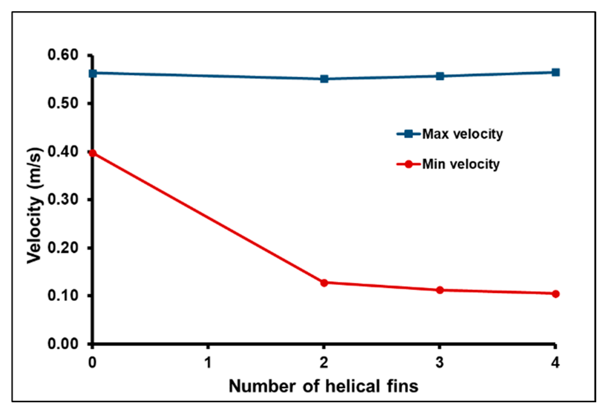
The results in Figure 11 depict the values of the maximum and minimum velocities as a function of the fins number in the solar receiver tube for a fin pitch of 400 mm, considering the same boundary conditions used in all the cases studied. It is evident that no significant difference arises among the evolutions of the maximum fluid velocities in the four cases studied, remaining almost identical for all cases. Instead, for what concerns the evolution of the minimum velocities, quite different values (0.4, 0.15 m/s) are registered if comparing the smooth tube and the finned tubes. In addition, it is found that there is no change in the velocity among the investigated cases of finned tubes with the change of the number of fins.

5. Conclusions

Through this study, a technological solution to increase the heat exchange in the receiver of a solar tower has been defined. This solution is using finned receiver tubes instead of smooth tubes. This solution remains among the possible improvements to be done in the future for solar receivers.
To increase the heat exchange, there are two possibilities: Either the convective exchange coefficient h increased by increasing the flow velocity and decreasing fluid temperature.
In most applications, the maximum increase of h is not sufficient to evacuate the desired heat flux and the cost is often too high. The second solution is easy to implement since it consists simply of increasing the exchange surface using fins. The thermal conductivity of the material constituting the fin must be high in order to minimize the temperature gradients between the base and the end of the fin.
In this study, the results show that the receiver tube with four fins is the best design. This tube can give high temperature and high heat transfer ratio compared to other designs. However, in the whole case:
  • The fins increase the heat flux transferred from the solid to the fluid.
  • In order to obtain higher temperatures, it is necessary to minimize the fin pitch.
  • The decrease of the fin pitch increases the flow velocity.
  • A significant change in temperature was noticed at the solar receiver output by increasing the number of fins.
  • The number of fins does not affect the values of the flow velocity.
Noted that the temperature is greater than 565 °C, which makes the molten salt lose its properties. To solve this problem, we have to decrease this temperature by:
  • Increasing the flow rate to decrease the temperature and thus produce more electrical energy.
  • Reducing the heliostats field to minimize the cost of projects and gain land surface.

Author Contributions

Conceptualization: M.H., B.A., and X.C.; Methodology: M.H. and M.D.; Software: M.H., and M.M.H.; Validation: B.A., X.C. and M.H.; Formal Analysis: M.H. and A.H.; Data Curation: M.H., M.D. and B.A.; Writing—Original Draft Preparation: M.H.; Writing—Review & Editing, D.-A.C.; Funding Acquisition: G.L. All authors have read and agreed to the published version of the manuscript.

Funding

This work was supported by a grant of the Romanian Ministry of Research and Innovation, CCCDI–UEFISCDI, project number PN-III-P1-1.2-PCCDI-2017-0404/31PCCDI/2018, within PNCDI III.

Conflicts of Interest

The authors declare no conflict of interest.

Abbreviation

Acronyms
CFDComputational Fluid Dynamics.
HTFHeat transfer fluid.
SPTSolar power tower.
SRRadiant heat source
3DThree-dimensional.
k-εTurbulence model.
Symbols
YOutlet vertical radial position (mm).
cpSpecific heat (J/kg · K)
Ddiameter (m)
Ggravity (m/s2)
Gktgeneration of turbulent kinetic energy due to the buoyancy force
Hconvective transfer coefficient
Kkinetic energy
ktturbulent kinetic energy
Llength (cm)
Ppressure (Pa)
Pktgeneration of the turbulent kinetic energy
Qconvective heat flux
Sexchange surface
T ˙ fluctuation of temperature (K)
T ¯ the mean temperature (K)
Ttemperature of fluid (K)
u i ˙ instant of fluctuation velocity in x direction (m/s)
uinlet velocity (m/s)
μ viscosity (kg/m.s)
x, y, zsystem coordinate
ρ density (kg/m3)
σ ε t ,   σ k t turbulent Prandtl number
εtdissipation of the turbulent kinetic energy
εdissipation of the kinetic energy
c 3 ε t ,   c 2 ε t dissipation of the kinetic energy

References

  1. Müller-Steinhagen, H.; Trieb, F. Concentrating Solar Power, A Review of the Technology; Institute of Technical Thermodynamics, German Aerospace Centre (DLR): Stuttgart, Germany, 2004. [Google Scholar]
  2. Choudhary, P.; Srivastava, R.K. Sustainability perspectives- a review for solar photovoltaic trends and growth opportunities. J. Clean. Prod. 2019, 227, 589–612. [Google Scholar] [CrossRef]
  3. Praveen, R.P. Performance analysis and optimization of central receiver solar thermal power plants for utility scale power generation. Sustainability 2020, 12, 127. [Google Scholar] [CrossRef] [Green Version]
  4. Garbrecht, O.; Al-Sibai, F.; Kneer, R.; Wieghardt, K. CFD-simulation of a new receiver design for a molten salt solar power tower. Sol. Energy 2013, 90, 94–106. [Google Scholar] [CrossRef]
  5. Pacio, J.; Wetzel, T. Assessment of liquid metal technology status and research paths for their use as efficient heat transfer fluids in solar central receiver systems. Sol. Energy 2013, 93, 11–22. [Google Scholar] [CrossRef]
  6. Xu, P.; Liu, J.; Xiang, Y.; Lei, Q.; Zhou, J.; Cen, K. Numerical simulation and experimental study of the tube receiver’s performance of solar thermal power tower. Energy Procedia 2014, 61, 1618–1621. [Google Scholar] [CrossRef] [Green Version]
  7. Boerema, N.; Morrison, G.; Taylor, R.A.; Rosengarten, G. High temperature solar thermal central-receiver billboard design. Sol. Energy 2013, 97, 356–368. [Google Scholar] [CrossRef]
  8. Pabst, C.; Feckler, G.; Schmitz, S.; Smirnova, O.; Capuano, R.; Hirth, P.; Fend, T. Experimental performance of an advanced metal volumetric air receiver for Solar Towers. Renew. Energy 2017, 106, 91–98. [Google Scholar] [CrossRef]
  9. Deng, Q.; Xiao, X.; Hao, Y.; Wang, Q.; Hu, T.; Wang, Y. Heat transfer performance evaluation of a large-size cavity receiver in the solar power tower plant based on angle factors. Sol. Energy 2017, 148, 78–86. [Google Scholar] [CrossRef]
  10. Uhlig, R.; Flesch, R.; Gobereit, B.; Giuliano, S.; Liedke, P. Strategies enhancing efficiency of cavity receivers. Energy Procedia 2014, 49, 538–550. [Google Scholar] [CrossRef] [Green Version]
  11. Rodríguez-Sánchez, M.R.; González, A.S.; Marugán-Cruz, C.; Santana, D. New designs of molten-salt tubular-receiver for solar power tower. Energy Procedia 2014, 49, 504–513. [Google Scholar] [CrossRef] [Green Version]
  12. Colomer, G.; Chiva, J.; Lehmkuhl, O.; Oliva, A. Advanced CFD&HT numerical modeling of solar tower receivers. Energy Procedia 2014, 49, 50–59. [Google Scholar] [CrossRef] [Green Version]
  13. Montes, M.J.; Rovira, A.; Martínez-Val, J.; Ramos, Á. Proposal of a fluid flow layout to improve the heat transfer in the active absorber surface of solar central cavity receivers. Appl. Therm. Eng. 2012, 35, 220–232. [Google Scholar] [CrossRef]
  14. González, A.S.; Santana, D. Solar flux distribution on central receivers: A projection method from analytic function. Renew. Energy 2015, 74, 576–587. [Google Scholar] [CrossRef]
  15. Qiu, K.; Yan, L.; Ni, M.; Wang, C.; Xiao, G.; Luo, Z.; Cen, K. Simulation and experimental study of an air tube-cavity solar receiver. Energy Convers. Manag. 2015, 103, 847–858. [Google Scholar] [CrossRef]
  16. Badar, A.W.; Buchholz, R.; Lou, Y.; Ziegler, F. CFD based analysis of flow distribution in a coaxial vacuum tube solar collector with laminar flow conditions. Int. J. Energy Environ. Eng. 2012, 3, 2251–6832. [Google Scholar] [CrossRef] [Green Version]
  17. Liao, Z.; Faghri, A. Thermal analysis of a heat pipe solar central receiver for concentrated solar power tower. Appl. Therm. Eng. 2016, 102, 952–960. [Google Scholar] [CrossRef]
  18. Maytorena, V.; Hinojosa, J. Three-dimensional numerical study of direct steam generation in vertical tubes receiving concentrated solar radiation. Int. J. Heat Mass Transf. 2019, 137, 413–433. [Google Scholar] [CrossRef]
  19. Montoya, A.; Rodríguez-Sánchez, M.R.; López-Puente, J.; Santana, D. Numerical model of solar external receiver tubes: Influence of mechanical boundary conditions and temperature variation in thermoelastic stresses. Sol. Energy 2018, 174, 912–922. [Google Scholar] [CrossRef]
  20. Wang, W.Q.; Qiu, Y.; Li, M.J.; Cao, F.; Liu, Z.B. Optical efficiency improvement of solar power tower by employing and optimizing novel fin-like receivers. Energy Convers. Manag. 2019, 184, 219–234. [Google Scholar] [CrossRef]
  21. Kanatani, K.; Yamamoto, T.; Tamaura, Y.; Kikura, H. A model of a solar cavity receiver with coiled tubes. Sol. Energy 2017, 153, 249–261. [Google Scholar] [CrossRef]
  22. Engineering Database of Liquid Salt Thermophysical and Thermochemical Properties. Available online: https://www.osti.gov/biblio/980801-engineering-database-liquid-salt-thermophysical-thermochemical-properties (accessed on 10 February 2020).
  23. Hazmoune, M.; Aour, B.; Chesneau, X.; Lazaroiu, G.; Hadjiat, M.M.; Debbache, M.; Ciupageanu, D.A. Influence of the geometric and mechanical parameters on the temperature evolution within the tubes of a receiver from a solar power tower, U.P.B. Sci. Bull. Ser. D 2020, 82, 1–14. [Google Scholar]
  24. Yang, X.; Yang, X.; Ding, J.; Shao, Y.; Fan, H. Numerical simulation study on the heat transfer characteristics of the tube receiver of the solar thermal power tower. Appl. Energy 2012, 90, 142–147. [Google Scholar] [CrossRef]
  25. Touahri, S. Phénomènes de Convection Mixte a Propriétés Variables dans les Conduits Cylindriques à Ailettes et Sans Ailettes. Ph.D. Thesis, Universite Mentouri, Constantine, Algeria, 6 December 2012. [Google Scholar]
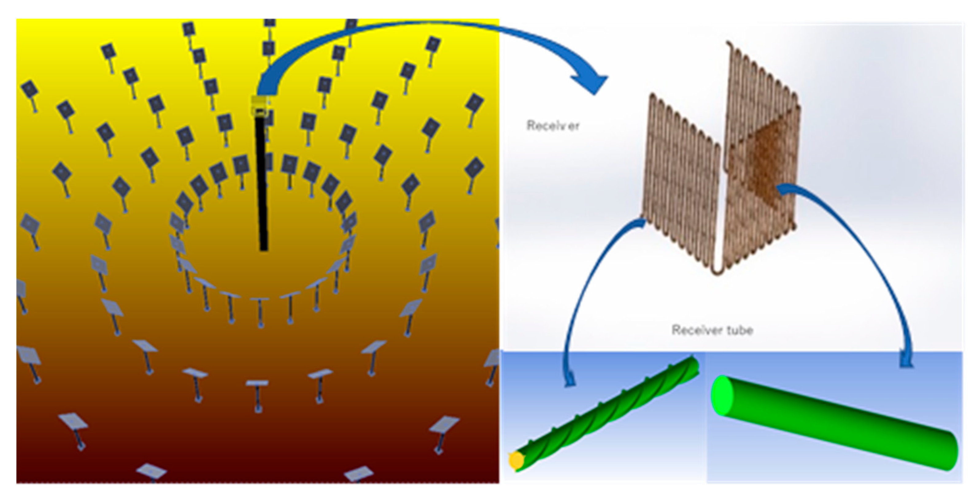
Figure 1. Presentation of the problem (solar tower, solar receiver, and solar receiver tube).
Sustainability 12 06957 g001
Figure 2. Receiver tube dimensions: (A) smooth, (B) finned.
Sustainability 12 06957 g002
Figure 3. Solar receiver tube: (A) smooth and (B) finned.
Sustainability 12 06957 g003
Figure 4. 2-D view of the smooth and finned receiver tube (2, 3, 4 fins).
Sustainability 12 06957 g004
Figure 5. Evolution of the temperature according to the pitch of the fin at the exit of the tube.
Sustainability 12 06957 g005
Figure 6. Influence of the pitch of the fin on the evolution of temperature. (A) temperature evolution; (B) max temperature evolution.
Sustainability 12 06957 g006
Figure 7. Velocity profile according to the fin pitch at the exit of the tube.
Sustainability 12 06957 g007
Figure 8. Velocity profile according to the fin pitch. (A) velocity profile. (B) max velocity profile.
Sustainability 12 06957 g008
Figure 9. Evolution of the temperature as a function of the number of fins at the outlet of the tube.
Sustainability 12 06957 g009
Figure 10. Evolution of the temperature according to the fin pitch at the exit of the tube. (A) max temperature evolution. (B) temperature evolution.
Sustainability 12 06957 g010
Figure 11. Evolution of the maximum and minimum values of velocity versus fins number.
Sustainability 12 06957 g011
Table 1. Properties of NaNO3-NaNO2-KNO3 molten salt used in this study [22].
QuantityValue
Mol % (Wt. %)7–49–44 (7–40–53)
Formula Weight (g/mol)1.77–1.98
Freezing/Melting Point (K)415
Boiling Point (K)1843
Density (kg/m3)1790
Specific Heat Capacity (J/kg·K)1560
Viscosity (kg/m·s)0.0013–0.0016
Thermal Conductivity (W/m·K)0.51–0.605
Prandtl No.4.0
Table 2. Pitch lengths of the four studied configurations.
ConfigurationPitch Length
Conf0150 mm
Conf02100 mm
Conf03200 mm
Conf04400 mm