Article

Special-Length-Priority Algorithm to Minimize Reinforcing Bar-Cutting Waste for Sustainable Construction

Department of Architectural Engineering, Kyung Hee University, Yongin-si, Gyeonggi-do 17104, Korea
*
Author to whom correspondence should be addressed.
Sustainability 2020, 12(15), 5950; https://doi.org/10.3390/su12155950
Submission received: 30 June 2020 / Revised: 19 July 2020 / Accepted: 21 July 2020 / Published: 23 July 2020

Abstract

:
Reinforcing bars (rebar), which have the most embodied carbon dioxide (CO2) per unit weight in built environments, generate a significant amount of cutting waste during the construction phase. Excessive cutting waste not only increases the construction cost but also contributes to a significant amount of CO2 emissions. The objective of this paper is to propose a special-length-priority cutting waste minimization (CWM) algorithm for rebar, for sustainable construction. In the proposed algorithms, the minimization method by special and stock lengths was applied. The minimization by special length was performed first, and then the combination by stock length was performed for the remaining rebar. As a result of verifying the proposed algorithms through a case application, it was confirmed that the quantity of rebar was reduced by 6.04% compared with the actual quantity used. In the case building, a CO2 emissions reduction of 406.6 ton-CO2 and a cost savings of USD 119,306 were confirmed. When the results of this paper are applied in practice, they will be used as a tool for sustainable construction management as well as for construction cost reduction.

1. Introduction

Building construction and operations accounted for 36% of global final energy use and nearly 40% of energy-related carbon dioxide (CO2) emissions in 2017 [1]. Concrete and reinforcing steel contribute about 65% of building greenhouse gases (GHG), 40% of which are CO2 emissions generated by concrete [2]. Clark and Bradley described that the mean embodied carbon dioxide (ECO2) for office buildings is 340 kg-CO2/m2, of which the structure accounts for approximately 60% [3]. In their research report, they suggest 95 kg-ECO2/ton for C25/30 concrete and 872 kg-ECO2/ton for reinforcing bar (rebar). This suggests that reducing the ECO2 in the structural frame directly produces a GHG reduction. In addition, in terms of the carbon footprint, efforts to reduce the rebar, which has an ECO2 of about 9.2 times that of concrete per unit weight [4], are very important.
In general, rebar cutting waste is estimated in the planning stage to be 3–5% [5,6,7,8] but more than 5% occurs in the actual construction stage [5,7,8,9,10,11,12,13]. This is because there is a lack of optimization technology on construction sites [14]. In order to solve this problem, many studies have been conducted to minimize rebar cutting waste [5,6,7,8,9,10,11,12,13,14,15,16,17,18,19,20,21,22,23,24,25]. Most studies use a stock length called a standard, or market length to make combinations that minimizes cutting waste [8,9,10,11,12,13,14,15,16,19,20,21,22,23,24,25]. In other words, they combine the rebar indicated in the structural drawings using stock lengths held in the rebar shop or plant in order to minimize cutting waste. If the rebar to be ordered by special length is used in the rebar combinations, cutting waste can be further reduced [5,7,14,17]. Rebar combinations using special lengths and stock lengths can further reduce the cutting waste and CO2 emissions. However, research on the use of special lengths for cutting waste minimization (CWM) in the construction industry is lacking. The study of Porwal and Hewage introduces the concept of special length combination [7], but constraints for minimization by special length (MSpL) are not clearly described. In addition, several studies have suggested the concept of MSpL but lack a detailed explanation of algorithm operation [7,14,17]. Additionally, from the viewpoint of sustainable construction, the effect of reducing CO2 emissions through minimization algorithms has not been suggested. Therefore, the objective of this paper is to propose a special-length-priority CWM algorithm for rebar, for sustainable construction.
The study proceeds as shown in Figure 1. First, we describe the originality of this paper and the lessons obtained after reviewing the references on CWM and the cutting stock problem (CSP). Then, we introduce the CWM algorithms, the core content of this paper. We describe in detail the concept of stock and special lengths, the CWM process and algorithms, and MSpL. Next, after applying the proposed algorithms to the case project, we analyze the rebar savings details. In addition, we confirm the CO2 emission and cost reduction effects associated with the rebar quantity reduction. Finally, we discuss the problems, lessons learned, and opportunities for further studies, and we describe the results of this present study.

2. Literature Review of CWM Problems

Research on CWM began with a study to solve the CSP. The study of the CSP was first mentioned by Kantorovich in 1939 and first published in Management Science in 1960 [26]. The problem consists of determining the best way of cutting a set of large objects into smaller items [27]. In operations research, the CSP is the problem to cut standard-sized pieces of stock material, such as rebar, paper rolls, or sheet metal, into pieces of specified sizes while minimizing the material wasted [28]. Kantorovich provides two examples in his paper to make the CSP easier to understand [26]. Since then, many scholars have conducted research to obtain a solution to the CSP using linear programming [29,30,31,32,33,34,35,36,37,38,39,40,41,42], genetic, or heuristic approaches [43,44,45,46,47,48].
In the case of rebar CWM, studies using linear programming and/or heuristic algorithms have been conducted [5,7,8,10,12,13,14,15,16,17,19,20,21,22,23,24,25]. In most cases, however, research has been conducted to minimize scrap or cutting waste using stock lengths, and the opportunity to further reduce cutting waste using special lengths has been lost. From the previous studies [5,14], we have confirmed that MSpL reduces cutting waste more than minimization by stock length (MStL). There have been several studies on minimization by special length (MSpL) [5,7,14,17], but various conditions required in practice have not been reflected in algorithms. Furthermore, the application process of MSpL reflecting these conditions was not specifically introduced. In the case of MSpL, variables such as minimum order quantity, rebar lengths for special order, minimum loss rate, and minimum and maximum combination length should be considered in practice. However, in most studies, these conditions were not reflected or sufficiently explained. In the paper of Porwal and Hewage [7], they proposed an algorithm for minimization by market and special lengths using rebar data extracted from building information modeling (BIM). However, detailed descriptions of constraints such as the rebar loss rate and minimum order quantity are not clearly described. In other papers [5,14,17], the MSpL concept was introduced, but detailed application processes were not described in their manuscripts.
In this paper, we propose algorithms that perform minimization by stock length on the rebar that is left after MSpL. However, since many scholars are familiar with MStL, MStL is first introduced, and MSpL is discussed later in the manuscript.

3. Cutting Waste Minimization Algorithms

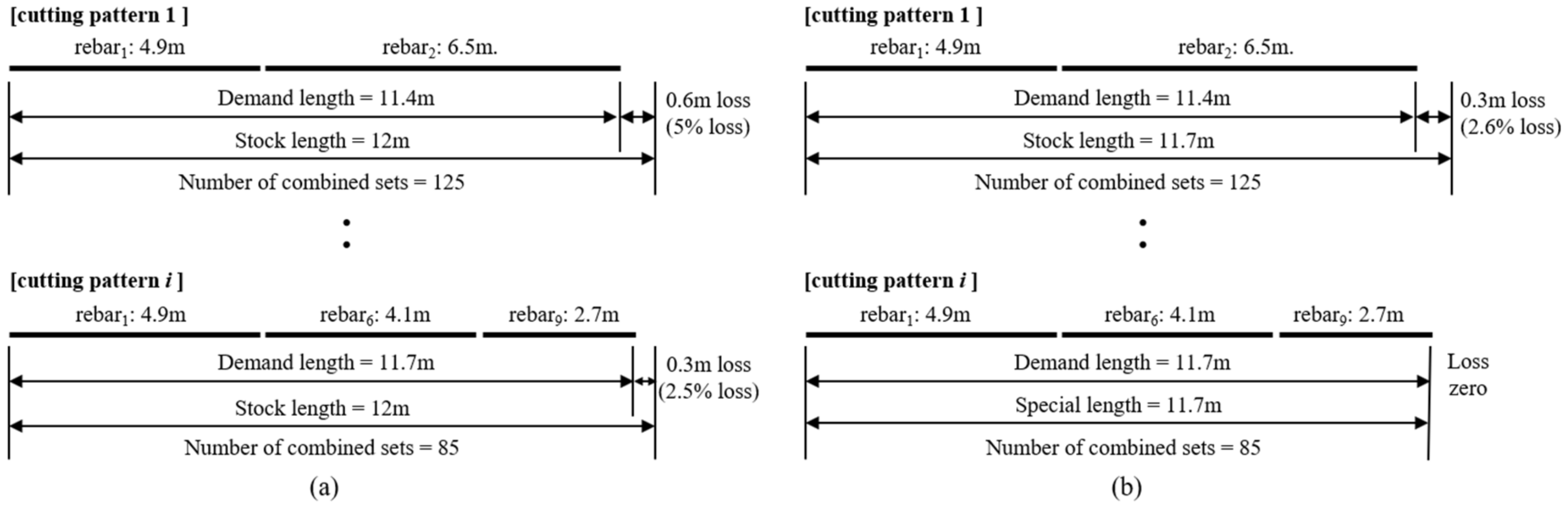
3.1. Definition of Stock and Special Lengths

Based on the examination of the studies to date, the CWM methods for rebar are largely divided into two types. Minimization by stock length (MStL) [5,7,8,10,12,13,14,15,16,17,20,21,22,23,24,25] and MSpL [5,7,14,17]. In these two methods, the target loss ratio and minimum quantity can be added as constraints [5,14,17]. Figure 2 is an example of combinations of stock lengths and special lengths. In the case of cutting pattern 1 in Figure 2a, two reinforcing bars are combined using a stock length of 12 m, and 0.6 m of cutting waste or loss occurs, which corresponds to a loss rate of 5%. In the case of cutting pattern i, three reinforcing bars are combined and 0.3 m of cutting waste is generated, which corresponds to a loss rate of 2.5%. If the special length of 11.7 m is used as shown in Figure 2b, in the same cases there is 0.3 m of cutting waste, a 2.6% loss rate, and a loss of zero, respectively. As shown in the examples, when using special lengths, the cutting waste is generally reduced more than with stock lengths.
For reference, “special length” means the length determined by the customer’s order, not the rebar length sold on the market. For example, stock or market length means the length determined by the producer in regular interval values such as 9, 10, 11, and 12 m, whereas special length includes irregular values such as 8.4, 9.7, and 10.1 m. Although there are differences by country, stock lengths of 7, 8, and up to 12 m are common in many countries, and when ordering rebar with special lengths, conditions for length, minimum quantity, and delivery time must be satisfied. In the case of Korea, orders must be made in 0.1-m intervals with a minimum quantity of 50 tons and a delivery time of two months or more. For example, rebar with a diameter of 25 mm and a length of 8.4 m can be obtained by special order in a quantity of 60 tons and a delivery time of two months.

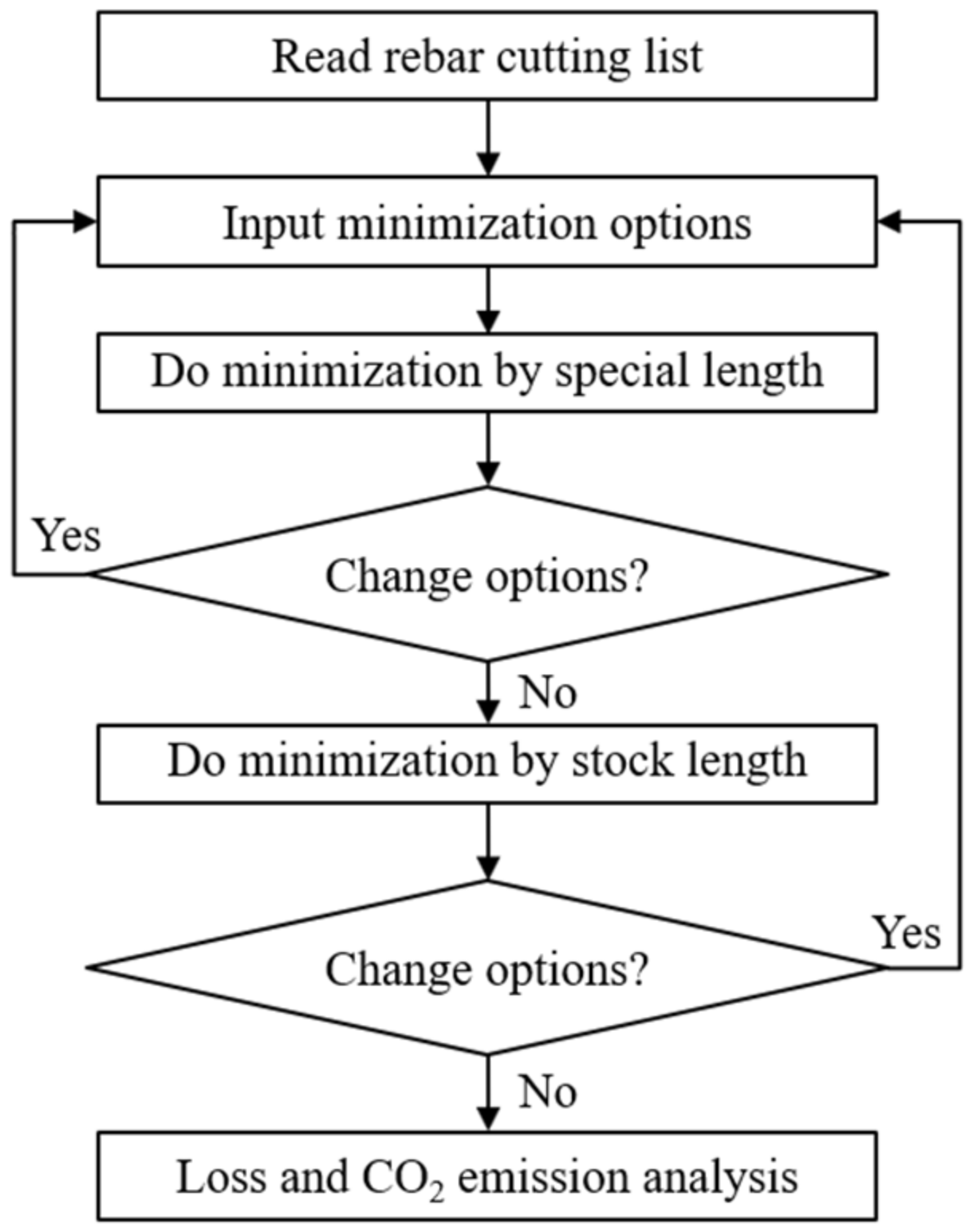
3.2. Cutting Waste Minimization Process

As mentioned earlier, rebar combination by special length provides an opportunity to reduce cutting waste or trim loss more than by stock length. Therefore, unlike the previous studies, which performed CWM by stock length only, the CWM algorithms proposed in this paper perform an MStL on the rebar that is left after performing an MSpL, as shown in Figure 3.
Figure 3 is described briefly as follows: (1) Read the rebar cutting list from the BIM [7] or computerized IPD system [17]; (2) Input options such as minimum and maximum lengths of rebar to be ordered, target loss rate, and minimum rebar quantity to be combined; (3) Execute the MSpL that satisfies the input options; (4) If the desired solution is not derived, decide whether to perform the MSpL again after mitigating options or perform an MStL; (5) If the desired solution cannot be derived from the MStL, decide whether to perform the optimization again by changing options. Otherwise, the process is terminated after analyzing the cutting waste and CO2 emissions.

3.3. Cutting Waste Minimization Algorithm

In general, CWM is performed for stock lengths using the objective function shown in Equation (1) as introduced in several studies [5,14,17]. This is a mathematical formulation that minimizes the difference between the length of the cutting pattern ( l i ) and the stock length L s t i obtained by combining multiple rebars. In this case, the constraints of Equations (2) to (4) must be satisfied. For reference, in Equation (2), l i corresponds to the demand length in Figure 2a, and r 1 ,   r 2 , .., r n correspond to rebar1, rebar2, rebarn. Equation (3) is not necessary if a single stock length is used, but it must be satisfied if several stock lengths are used. In the case of construction sites, the conditions of Equation (3) are generally valid because rebar of multiple market lengths can be purchased.
Minimize   f ( X i ) = i = 1 N L s t i n i l i n i / L s t i n i
Subject   to   l i L s t i ,   l i = r 1 + r 2 + + r n
L m i n L s t i L m a x 0
< n i ,   integer ,   i = 1 ,   2 , ,   N
Here,
L s t i = Stock length of cutting pattern i (m)
l i = Length of cutting pattern i obtained by combining multiple rebars, demand lengths (m)
n i = Number of rebar combinations with the same cutting pattern i
r i = Length of combined rebar (m)
L m i n = Minimum length of rebar to be ordered (m)
L m a x = Maximum length of rebar to be ordered (m).
So far, most rebar optimization studies in the construction sector have been conducted for MStL. This is because materials such as rebar, structural steel, pipes, and timber are supplied by the manufacturer in market lengths. If the target loss rate is added as a constraint to the CWM, Equation (5) should be used. In this case, the combination is executed only when the loss rate ε caused by the cutting pattern is less than or equal to the target loss rate ε t . When MSpL is performed, the loss rate can be further reduced but many algorithms have focused on MStL because of the complexity of the optimization algorithms.
ε = L s t i l i L s t i ε t
Here,
ε t = Target cutting waste or loss rate (%)
ε = Cutting waste or loss rate (%).

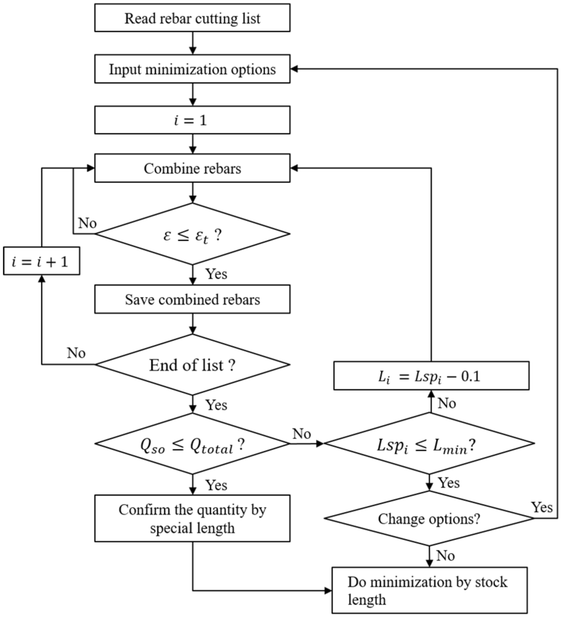
3.4. Minimization by Special Length

The mathematical formulation of CWM by special length is described in Equations (7)–(11), which is similar with previous studies [5,7,14]. Special lengths ( L s p i ) that satisfy constraints such as the target loss (scrap or waste) rate ε t and minimum quantity for special order ( Q s o ) must be searched. In this case, the special length must be within the range of minimum ( L m i n ) and maximum ( L m a x ) lengths where special orders are possible.
Minimize   f ( X i ) = i = 1 N L s p i n i l i n i / L s p i n i
Subject   to   l i L s p i ,   l i = r 1 + r 2 + + r n
L m i n L s p i L m a x ,
ε = L s p i l i L s p i ε t ,
Q s o Q t o t a l , 0
< n i ,   integer ,   i = 1 ,   2 ,   ,   N
Here,
l i = Length of cutting pattern i obtained by combining multiple rebars, demand lengths (m)
L s p i = Special length of cutting pattern i that satisfies the target loss rate (m)
L m i n = Minimum length of rebar to be ordered (m)
L m a x = Maximum length of rebar to be ordered (m)
n i = Number of rebar combinations with the same cutting pattern i
r i = Length of combined rebar (m)
ε = Cutting waste or loss rate (%)
ε t   = Target cutting waste or loss rate (%)
Q t o t a l = Total combined rebar quantity (ton)
Q s o = Minimum rebar quantity to be special ordered (ton).
For example, in the case where the loss rate is less than 2%, the length is between 8 and 12 m at intervals of 0.1 m, but the total quantity ( Q t o t a l ) of the same length that will be more than 50 tons is searched. The MSpL that satisfies these conditions proceeds with the process shown in Figure 4. The minimization process in that figure is described in pseudocode, as follows:
(1)
After the rebar cutting list is read, in which the number of reinforcing bars by diameter and length is counted, it is sorted in descending order with length and number priority. This is for efficient performance of the quantity–priority combination.
(2)
Options such as the maximum ( L m a x ) and minimum ( L m i n ) lengths of rebar to be ordered, target loss rate ε t , and minimum rebar quantity ( Q s o ) to be special ordered are entered. If the target loss rate is not entered, the combination that satisfies the condition of Q s o with a special length priority is executed by default.
(3)
The rebar combination ( l i ) that satisfies L m i n L s p i L m a x for rebar of the same diameter is executed in descending order from the maximum length ( L m a x ) of rebar to be ordered. If L s p i l i / L s p i ε t is satisfied, the next combination i = i + 1 is executed until the end of the list after saving the result of combination, or the combination is performed until the loss rate condition is satisfied. This is because executing the combination in descending order from the maximum length is effective in performing the quantity–priority combination, as described in step (1).
(4)
Next, the total quantity of combined rebar is calculated by Equation (12).
Q t o t a l = w i = 1 N L s p i n i
here, w = unit weight of combined rebar per meter (ton/m).
(5)
If Q s o Q t o t a l is not satisfied, MSpL is repeated while L s p i is decreased by 0.1 m until L s p i L m i n is satisfied. If a solution that satisfies the constraints is not found in the process so far, it should be decided whether to perform the minimization again after alleviating the combination conditions. Otherwise, MStL must be subsequently performed.
If Q s o Q t o t a l is satisfied, the quantity of special length is determined and MStL is executed for the remaining rebar. As all of the rebar is not combined by special length, minimization is performed with stock lengths for the remaining ones.

4. Verification of CWM Algorithms

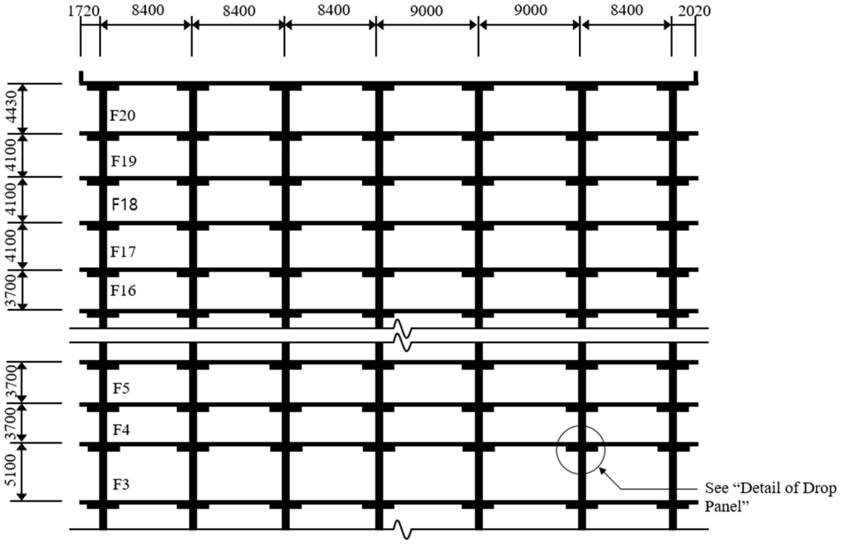
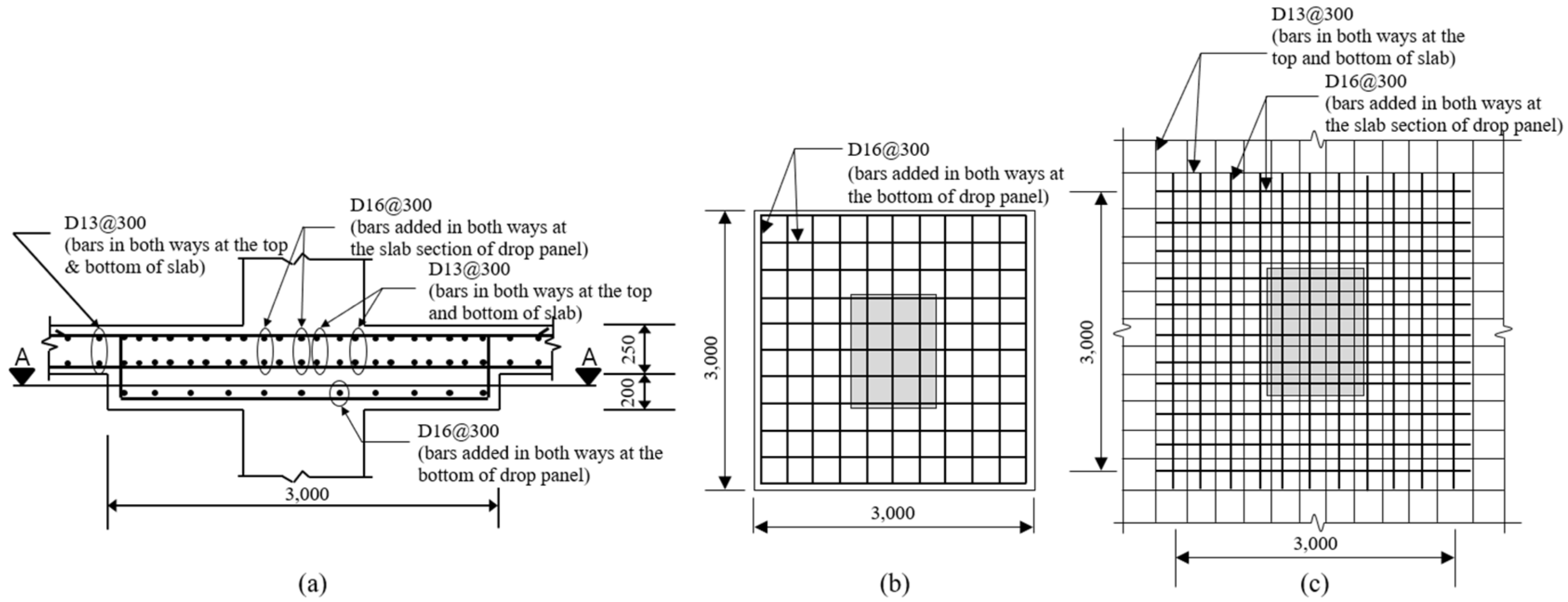
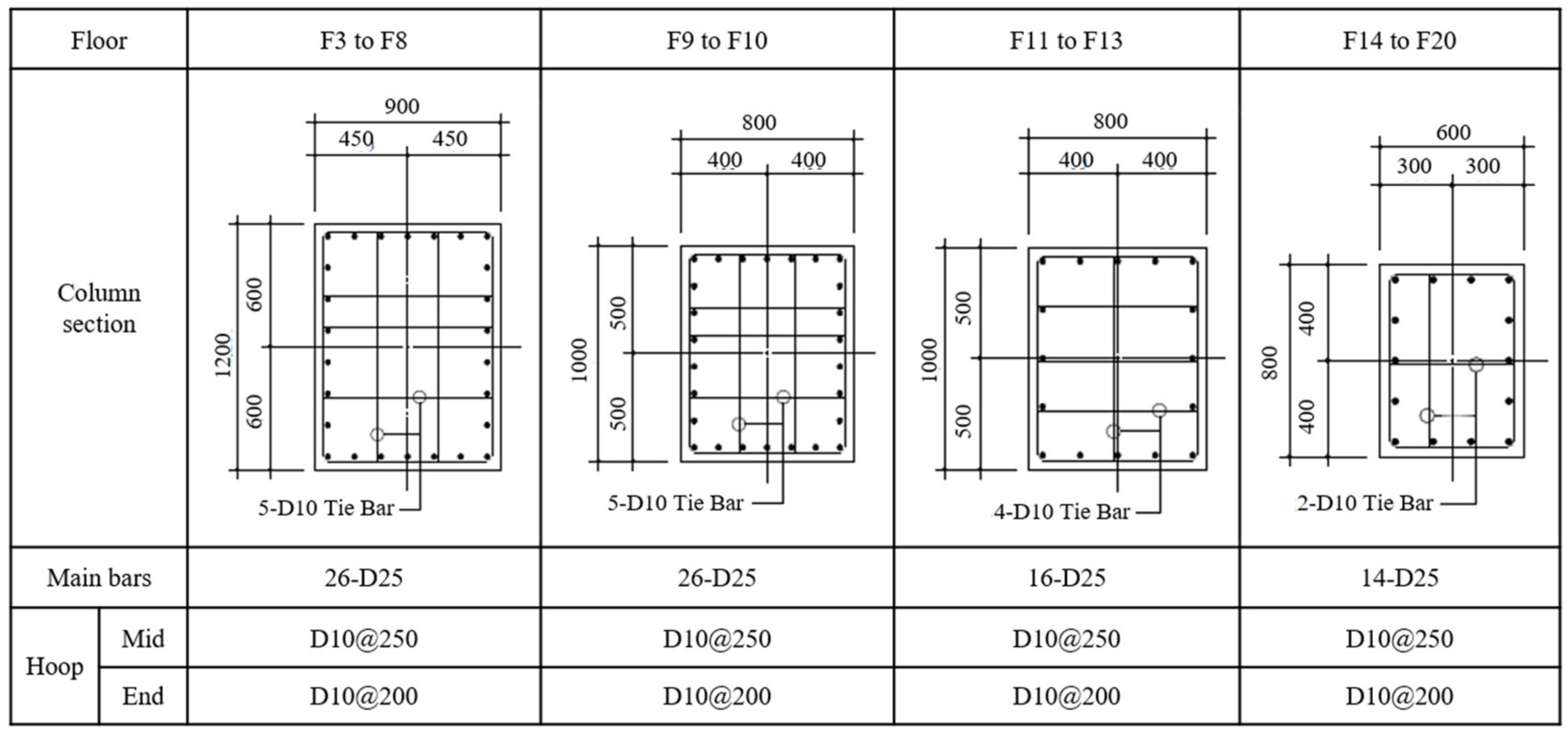
4.1. Brief Description of the Case Project

The effectiveness of CWM algorithms by stock and special lengths described so far should be verified through case application. To this end, the case project shown in Table 1 was selected in this study. This is a commercial building project constructed in Seoul, Korea, with a total floor area of 66,644 m2, three basement levels, and 20 floors above ground. The site area of the case project is not large enough for rebar work on site. Moreover, considering the quality, time, and safety, the rebar was supplied from the plant.
Reviewing the structure of the case building, the underground structure is steel reinforced concrete (SRC) and the superstructure is reinforced concrete (RC). In addition, the first and second floors are designed as a column-and-beam structure, and as shown in Figure 5, from the 3rd floor to the 20th floor, it is designed as a flat slab structure. That is, the case building includes three types of structures. For effective verification of the proposed CWM algorithms, as shown in Figure 5, the case application is performed on the flat slab structure from the 3rd floor to the 20th floor, which is the largest part of the building.
The flat slab structure of the case project is composed of columns, slabs, and drop panels. Therefore, as shown in Figure 5 and Figure 6, the top of each column is reinforced by drop panels. Figure 6a is the sectional detail of the drop panel that is most frequently applied to the case structure, and below the drop panel, 11-D16s are reinforced at 300-mm intervals as shown in Figure 6b. In the case of the slab part, D13 is installed at 300-mm intervals in both directions on the upper and lower sides as shown in Figure 6c. Furthermore, at the top of the drop panel, D16 is additionally reinforced at 300-mm intervals over the width of the column strip. As shown in Figure 6a, the slab thickness is 250 mm, and the drop panel thickness is 450 mm (200 mm thicker than the slab). For reference, the cross-section of deformed bars is variously marked in many countries as Y, H, D, etc. In the case of this paper, it is denoted by D (Deformed bar), which is commonly used in Korea.
For the columns of the case project, as shown in Figure 5 and Figure 7, all of them, including C3, have four sections with different reinforcements, such as 900 × 1200, 800 × 1000, and 600 × 1000, from F3 to F20. This is because the design was optimized according to the change in the load condition of each floor. As shown in Figure 7, the main bars are designed to have 26, 16, and 14 deformed bars with a diameter of 25 mm, gradually decreasing in number. Additionally, the sizes and combinations of tie bars and hoops designed for buckling vary from 5-D10 at F3 to F10, to 2-D10 at F14 to F20, as shown in Figure 7. For reference, the 5-D10 tie bars and hoops consist of five deformed tie bars and one hoop with a diameter of 10 mm. The columns shown in Figure 5 and Figure 7 are connected by mechanical couplers, so there is no splice lapping. Therefore, according to the cross-sectional change, the rebar that is installed continuously in the upper and lower columns is connected by couplers, but the rest of it is anchored to the upper column. The case building has less rebar than the structure size because, in order to reduce the cross-sections of the structural members, super-high-tensile deformed (SHD) bars with a yield strength of 500 MPa were used for D10 and D13, and ultra-high-tensile deformed (UHD) bars with a yield strength of 600 MPa were used for D16, D19, and D25.

4.2. Application of CWM Algorithms

In this study, for the verification of the proposed algorithm, rebar combinations were performed on structural frames from F3 to F20. The rebar cutting list generated from the bar-bending schedule was used for rebar information. At the case site, various diameters of rebar were used. For example, in the case of the column in Figure 7, 25-mm-diameter rebar was used for the main bar, and 10-mm-diameter rebar was used for the hoop. Table 2 and Table 3 show the combination results of the CWM algorithms for the main bars of all of the columns.
Table 2 shows the results of minimization by MSpL according to Equations (6) to (11), and the final loss rate, i.e., cutting waste rate, was calculated to be 0.58%. A detailed description of Table 2 is as follows: (a) Combination is performed on the 25-mm rebar in the bar-cutting list file named “proj101_bcl.dat”: (b) The minimum quantity of special length is 50 tons after combination for rebar with a minimum length of 6.0 m and a maximum length of 10.0 m, and the maximum loss rate is not specified as 3.0%; (c) Cutting pattern S1 has the same combined and order lengths of 7.4 m, so the loss rate is zero for the order quantity of 176.2 tons; (d) The combined and order lengths of the cutting pattern S2 are equal to 9.2 m, so the loss rate is zero for the order quantity of 42.8 tons; (e) Finally, in cutting pattern S3, the combined length is 8.53 m, but in order to satisfy the minimum order weight of 50 tons, 18.82 tons must be ordered with a length of 9.2 m, in which case the loss rate is increased to 7.85%. However, as shown in Table 2, the quantity of S3 is relatively small compared with S1 and S2. Therefore, the loss rate of the final MSpL is 0.58%, which corresponds to 1.37 tons of cutting waste.
For reference, in the case structural frame, 25-mm-diameter rebar was used for the columns only. Additionally, there were not many cutting patterns because there were many main rebars of the same length. In other words, as shown in Figure 5, the lengths of the main rebars of all of the columns on the same floor were the same and the length was changed according to the change in floor height. The total number of main rebars in the case frame was 15,734, which were identified in five lengths.
Table 3 shows the results of MStL by Equations (1) to (4), and the final loss rate was calculated as 1.58%. In Table 2, the cutting pattern is combined into one because it is performed on the remaining rebar after combination by special length. For cutting pattern N1, the combined length is 8.86 m and the stock length is 9.0 m. The combined and stock weight are 1.65 and 1.68 tons, respectively, and the loss rate is 1.58%. For reference, in the case of MStL, the combination conditions are the same as for MSpL but the minimum weight is not specified. This is because it is assumed that there is a sufficient quantity in stock.
Comparing the results of Table 2 and Table 3, the minimization results by special length have a lower loss rate than by stock length. This is because combination by special length is performed to further reduce the loss rate.
Table 4 shows the results of applying CWM algorithms to all types of rebar used in the case structural frame in Figure 5, Figure 6 and Figure 7. Five diameters of rebar were used, and a total loss rate of 0.96% was calculated. The total quantity of rebar required for construction is 1.807.45 tons, and the quantity to be supplied in special and stock lengths is 1.824.75 tons. The loss rate is different for each diameter of rebar depending on the design characteristics of the structural member in which each rebar is used. The details are as follows.
D10, D13, and D16 are mostly rebars that are repeatedly used in various structural members such as slabs, staircase walls, stairs, hoops, and drop panels. In those applications, many rebars of the same length are placed in the same type of structural members. In addition to these characteristics, small-diameter rebar left after cutting for primary use can be used for various other purposes. For example, they can be used as diagonal bars for crack reinforcement, reinforcement of openings, etc. Therefore, the cutting waste rate is lower than that of large-diameter rebar. Moreover, the combined weight was sufficient to cover the various cutting patterns, so MSpL and MStL using the CWM algorithms were performed smoothly.
In the case of D19, MStL was performed because there was no combination that met the minimum weight for a special order (50 tons). As a result, the cutting waste rate increased. Lastly, in the case of D25, most of the rebar was combined with the MSpL algorithm, as described in Table 2 and Table 3, so the cutting waste rate was the lowest.

4.3. Comparison of Actual and Optimized Rebar Quantities

In order to verify the effectiveness of CWM algorithms, actual and optimized rebar quantities must be compared. As shown in Table 5, the actual quantity of rebar in the case structural frame is 1.942.05 tons and the quantity optimized by the CWM algorithms is 1.824.75 tons. As a result, 117.30 tons were saved, which is 6.04% of the actual quantity. It can be seen from this table that the reduction rate differs significantly for each diameter of rebar.
As described above, small-diameter rebar had more secondary use after cutting. Therefore, it is common that less cutting waste is generated with small-diameter rebar. However, in Table 5, the 10.27% reduction rate for D10 is higher than that of D13 and D16, which means that the loss rate of the actual quantity of rebar is higher than the optimized one. The high quantity reduction rate calculated after optimization by the CWM algorithms means that the loss rate of the actual rebar quantity is high. The reason is presumed to be a problem with the rebar work management. In addition, Table 5 confirms a relatively small loss rate for D13 and D16. This is because there are many rebars with the same lengths repeatedly used in structural members such as slabs, staircase walls, and drop panels.
In the case of D19, it is confirmed that the cutting waste is increased because the quantity required for the work is relatively small and there are not many rebars of the same length placed repeatedly. However, it is confirmed that a cutting waste reduction of 12.39% can be obtained using the CWM algorithms proposed in this study. Lastly, in the case of D25, it is used for the main rebar of the columns, and it is relatively easy to manage the rebar to reduce cutting waste because there are not many changes in length. Therefore, it is confirmed that the quantity reduction of this rebar by optimization is 3.75%, which is smaller than that of the other types of rebar, as shown in Table 5. For reference, when the reduced rebar quantity of 117.3 tons is converted into money, it is about USD 98,976 including material, cutting and bending, and placement costs.

4.4. CO2 Emission Reduction Effects

When using the CWM algorithms proposed in this study, the contribution to sustainable construction should be confirmed. For this, Table 6 shows the quantitative calculation of the CO2 emissions for rebar saved by the algorithms. Substituting 3.466 ton-CO2/ton [49], the unit CO2 emissions of high-tensile deformed bar published by the Korea Institute of Construction Technology (KICT), show that the CO2 emissions from the actual rebar work and the optimized result are calculated to be 6.731.15 and 6.324.58 tons, respectively. For reference, the LCI DB (Life Cycle Inventory Database) varies by country, and this study cited the data presented in the research report of the government-funded research institute, KICT. In addition, because the LCI DB for SHD and UHD used in the case project has not been officially provided, the unit CO2 emission data for high-tensile deformed bar are cited in this paper.
As shown in Table 6, when the CWM algorithms are applied, it can be seen that the case project has a CO2 emission reduction of 406.60 tons which is equivalent to 6.04% of the structure. As mentioned in the introduction, in the case of buildings, the structure accounts for about 65% of building GHGs [3]. Considering this reference, there is a CO2 emission reduction of 3.93% based on the whole building. From a carbon footprint point of view, the embodied CO2 per unit weight or volume of rebar is about 9.02 times that of concrete [4]; therefore, the CO2 emission reduction produced by the CWM algorithms has a great effect on sustainable construction.
It is necessary to confirm the cost reduction effect by converting the CO2 emission reduction effect to the carbon price. To this end, the cost savings of USD 20,330 can be confirmed when applying the Korean carbon transaction price of USD 50/ton-CO2 [50] announced by the Carbon Disclosure Project (CDP). When this amount is added to the previously calculated savings of USD 98,976 in construction cost, a total savings of USD 119,306 is confirmed. Similar to LCI DB, the annual price of carbon traded by CDP varies by country. According to CDP data, in the case of Korea, the price was USD 64/ton-CO2 in 2016 and USD 50/ton-CO2 in 2017, which is USD 14/ton-CO2 lower than the previous year.
The proposed algorithms were applied to the 3rd to 20th floors, designed as a flat slab structure, which is part of the case project. The amount of rebar used in the entire structural frame of the case project was found to be 3.444.06 tons. Therefore, if the CWM algorithms proposed in this study are applied to the entire structural frame, greater CO2 emission and cost reductions are expected.

5. Discussion

In this study, as shown in Figure 3, we proposed an algorithm that performs MStL on the rebar that remains after special length minimization. With this algorithm, cutting waste or trim loss is further reduced because, as illustrated in Figure 2, the special length is combined at 0.1-m intervals, unlike the stock length, which is generally combined at 1-m intervals. This is also confirmed by the results shown in Table 2 and Table 3.
Through this study, we confirmed that additional in-depth studies are needed on these two issues. First, it is possible to combine all of the rebar for one project at the same time, but the results may not be practical. For example, rebar placed on the first and 20th floors can be combined. In this case, the inventory management cost may be high because there is a significant time difference between the use of rebar on the 1st floor and the use of the remaining rebar on the 20th floor. Therefore, the combination condition for rebar to be used within a certain time must be added. For example, the condition for performing a combination of rebar to be used within two weeks should be added. So far, most of the papers related to CSP do not consider the time factor. If the required rebar information can be obtained automatically from the BIM [7] or from an integrated project delivery system [17] linked to the schedule, this problem can be easily solved.
Existing CSP-related studies, including this paper, use original rebar information generated after the structural design. In this case, there are different amounts of rebar of various lengths, and numerous combinations are repeated to search for solutions. Additionally, as mentioned above, rebar scattered in various locations are combined. In addition to cutting patterns that are difficult to apply practically, cutting waste rates cannot be reduced below a certain level [5]. However, it was confirmed that near-zero cutting waste could be achieved by realigning the rebar in the drawings created after the structural design in special lengths using heuristic algorithms. It was also confirmed that heuristic algorithms would be more efficient than mathematical algorithms in performing rebar realignment. Therefore, further studies on the rebar alignment algorithm for near-zero cutting waste should be performed for sustainable construction.
During the case study, it was confirmed that significant efforts have been made from the structural design stage to increase the productivity of rebar work and reduce the rebar loss rate. For example, it is common for some Korean companies to use 500- or 600-MPa super- or ultra-tensile bars instead of 400-MPa high-tensile deformed bar, and to use couplers to connect rebar more than 20 mm in diameter. The goal of near-zero cutting waste for sustainable construction is expected to be achieved if heuristic rebar alignment algorithms are applied along with these efforts.

6. Conclusions

Efforts to reduce carbon and climate change risk are being carried out globally and in all industries. In particular, rebar, which has the most ECO2 per unit weight in built environments, generates a significant amount of cutting waste in the construction phase. Therefore, there is not only the cost of rebar construction but also a considerable amount of CO2 emissions to be expected. To solve this issue, we proposed rebar CWM algorithms for sustainable construction. The effectiveness of the proposed algorithms was verified through a case project, and the following results were obtained.
First, in the case of the optimization of D25 rebar, the cutting waste rate for special lengths was 0.58%, whereas that for stock lengths was 1.58%. This proved the assumption that combination by special length reduced the loss rate more than combination by stock length.
Furthermore, although the actual quantity of rebar put into the case project was 1942.05 tons, the quantity optimized by the proposed algorithms was 1824.75 tons, which represented a quantity reduction of 117.3 tons. This corresponds to 6.04% of the actual quantity and a savings of USD 98,976 in construction costs.
In addition, CO2 emissions by the proposed optimization algorithms compared with actual emissions had a reduction of 406.6 ton-CO2. This corresponds to a CO2 emission reduction of 3.93% based on the whole building, reflecting that the structure accounts for about 65% of building GHGs [3]. This is a savings of USD 20,330 based on the carbon trade price in Korea, and a total savings of USD 119,306, including a reduction in construction costs. The quantity of rebar used in the entire building of the case project, including the flat slab structure on the 3rd to 20th floors, was found to be 3444.06 tons. If the proposed algorithms had been applied to the entire building, further CO2 and cost savings would have been expected.
These results confirmed that the proposed CWM algorithms worked as an effective tool for sustainable construction. During this study, it was observed that near-zero cutting waste could be achieved by realigning the rebar in the structural drawings to special lengths. In other words, it was observed that repositioning rebar of a certain length while satisfying the structural design criteria might significantly reduce cutting waste. In order to do this efficiently, heuristic algorithms of a new concept rather than the mathematical algorithms proposed in this study should be developed in the future.

Author Contributions

Conceptualization, S.K.; methodology, S.K.; validation, D.L., S.S. and D.K.; formal analysis, D.L., S.S. and S.K.; investigation, D.K.; data curation, D.K.; writing—original draft preparation, D.L. and S.K.; writing—review and editing, D.L. and S.K.; visualization, S.S.; supervision, S.K.; project administration, S.K.; funding acquisition, S.K. All authors have read and agreed to the published version of the manuscript.

Funding

This work was supported by the National Research Foundation of Korea (NRF) grant funded by the Korean government (MOE) (no. 2017R1D1A1B04033761).

Acknowledgments

The authors thank SK E&C for providing the rebar data of the case project to verify the CWM algorithms.

Conflicts of Interest

The authors declare no conflict of interest. The funders had no role in the design of the study; in the collection, analyses, or interpretation of data; in the writing of the manuscript, or in the decision to publish the results.

References

  1. International Energy Agency and the United Nations Environment Programme. 2018 Global Status Report: Towards a Zero-Emission, Efficient and Resilient Buildings and Construction sector. 2018, p. 9. Available online: https://www.worldgbc.org/sites/default/files/2018%20GlobalABC%20Global%20Status%20Report.pdf (accessed on 19 April 2020).
  2. Pacheco-Torgal, F.; Cabeza, L.; Labrincha, J.; De Magalhaes, A. Eco Efficient Construction and Building Materials: Life Cycle Assessment (LCA), Eco-Labelling and Case Studies; Elsevier: Cambridge, UK, 2014; Volume 1, pp. 624–630. [Google Scholar]
  3. Clark, D.; Bradley, D. Information Paper—31: Embodied Carbon of Steel Versus Concrete Buildings; Cundall Johnston & Partners LLP: Newcastle, UK, 2013; p. 4. [Google Scholar]
  4. Lee, I.J.; Yu, H.; Chan, S.L. Carbon Footprint of Steel-Composite and Reinforced Concrete Buildings, Standing Committee on Concrete Technology Annual Concrete Seminar 2016, Hong Kong, 20 April 2016; Construction Industry Council. Available online: https://www.devb.gov.hk/filemanager/en/content_971/7_Carbon_Footprint_for_Steel_Composite_and_Reinforced_Concrete_Buildings.pdf (accessed on 22 April 2020).
  5. Kim, S.K.; Kim, M.H. A Study on the development of the optimization algorithm to minimize the loss of reinforcement bars. J. Archit. Inst. Korea 1991, 7, 385–390. [Google Scholar]
  6. Kim, G.H. A Study on Program of Minimizing the Loss of Re-Bar. Master’s Thesis, Korea University, Seoul, Korea, 2002; pp. 8–58. [Google Scholar]
  7. Porwal, A.; Hewage, K.N. Building information modeling-based analysis to minimize waste rate of structural reinforcement. J. Constr. Eng. Manag. 2012, 138, 943–954. [Google Scholar] [CrossRef]
  8. Poonkodi, N. Development of software for minimization of wastes in rebar in rcc structures by using linear programming. Int. J. Adv. Res. Trends Eng. Technol. (IJARTET) 2016, 3, 1262–1267. [Google Scholar]
  9. Nadoushani, Z.; Hammad, A.; Akbar Nezhad, A. A Framework for Optimizing Lap Splice Positions within Concrete Elements to Minimize Cutting Waste of Steel Bars. In Proceedings of the 33th International Symposium on Automation and Robotics in Construction (ISARC 2016), Auburn, AL, USA, 21 July 2016. [Google Scholar] [CrossRef]
  10. Shahin, A.A.; Salem, O.M. Using genetic algorithms in solving the one-dimensional cutting stock problem in the construction industry. Can. J. Civ. Eng. 2004, 31, 321–332. [Google Scholar] [CrossRef]
  11. Chandrasekar, M.K.; Nigussie, T. Rebar Wastage in Building Construction Projects of Hawassa, Ethiopia. Int. J. Sci. Eng. Res. 2018, 9, 282–287. [Google Scholar]
  12. Nadoushani, Z.S.M.; Hammad, A.W.; Xiao, J.; Akbarnezhad, A. Minimizing cutting wastes of reinforcing steel bars through optimizing lap splicing within reinforced concrete elements. Constr. Build. Mater. 2018, 185, 600–608. [Google Scholar] [CrossRef]
  13. Zubaidy, S.S.; Dawood, S.Q.; Khalaf, I.D. Optimal utilization of rebar stock for cutting processes in housing project. Int. Adv. Res. J. Sci. 2016, 3, 189–193. [Google Scholar] [CrossRef]
  14. Kim, S.K.; Hong, W.K.; Joo, J.K. Algorithms for reducing the waste rate of reinforcement bars. J. Asian Archit Build. 2004, 3, 17–23. [Google Scholar] [CrossRef]
  15. 44/12 Benjaoran, V.; Bhokha, S. Trim loss minimization for construction reinforcement steel with oversupply constraints. J. Adv. Manag. Sci. 2013, 1, 313–316. [Google Scholar] [CrossRef] [Green Version]
  16. Benjaoran, V.; Bhokha, S. Three-step solutions for cutting stock problem of construction steel bars. KSCE J. Civ. Eng. 2014, 18, 1239–1247. [Google Scholar] [CrossRef]
  17. Kim, D.; Lim, C.; Liu, Y.; Kim, S. Automatic Estimation System of Building Frames with Integrated Structural Design Information (AutoES). Iranian J. Sci. Tech. Trans. Civ. Eng. 2019, 1–13. [Google Scholar] [CrossRef]
  18. Hwang, J.W.; Park, C.J.; Wang, S.K.; Choi, C.H.; Lee, J.H.; Park, H.W. A Case Study on the Cost Reduction of the Rebar Work through the Bar Loss Minimization. In Proceedings of the KIBIM Annual Conference 2012, Seoul, Korea, 19 May 2012; Volume 2, pp. 67–68. [Google Scholar]
  19. Khalifa, Y.; Salem, O.; Shahin, A. Cutting Stock Waste Reduction using Genetic Algorithms. In Proceedings of the 8th Annual Conference on Genetic and Evolutionary Computation, Seattle, WA, USA; 2006; pp. 1675–1680. [Google Scholar] [CrossRef]
  20. Salem, O.; Shahin, A.; Khalifa, Y. Minimizing cutting wastes of reinforcement steel bars using genetic algorithms and integer programming models. J. Constr. Eng. Manag. 2007, 133, 982–992. [Google Scholar] [CrossRef]
  21. Gilmore, P.C.; Gomory, R.E. A linear programming approach to the cutting-stock problem. Oper. Res. 1961, 9, 849–859. [Google Scholar] [CrossRef]
  22. Nanagiri, Y.V.; Singh, R.K. Reduction of wastage of rebar by using BIM and linear programming. Int. J. Tech. 2015, 5, 329–334. [Google Scholar] [CrossRef]
  23. Zheng, C.; Yi, C.; Lu, M. Integrated optimization of rebar detailing design and installation planning for waste reduction and productivity improvement. Autom. Constr. 2019, 101, 32–47. [Google Scholar] [CrossRef]
  24. Zheng, C. Multi-Objective Optimization for Reinforcement Detailing Design and Work Planning on a Reinforced Concrete Slab Case. Master’s Thesis, Alberta University, Edmonton, Canada, 2018. [Google Scholar] [CrossRef]
  25. Zheng, C.; Lu, M. Optimized reinforcement detailing design for sustainable construction: Slab case study. Procedia Eng. 2016, 145, 1478–1485. [Google Scholar] [CrossRef] [Green Version]
  26. Kantorovich, L.V. Mathematical methods of organizing and planning production. Manag. Sci. 1960, 6, 366–422. [Google Scholar] [CrossRef]
  27. Ben Amor, H.; Valério de Carvalho, J. Cutting stock problems. In Column Generation; Springier: Boston, MA, USA, 2005; pp. 131–161. [Google Scholar] [CrossRef]
  28. Cutting Stock Problem. Available online: https://en.wikipedia.org/wiki/Cutting_stock_problem (accessed on 20 April 2020).
  29. Arbib, C.; Marinelli, F.; Ventura, P. One-dimensional cutting stock with a limited number of open stacks: Bounds and solutions from a new integer linear programming model. Int. Trans. Oper. Res. 2016, 23, 47–63. [Google Scholar] [CrossRef]
  30. Berberler, M.; Nuriyev, U.; Yildirım, A. A Software for the one-dimensional cutting stock problem. J. King Saud Univ. Sci. 2011, 23, 69–76. [Google Scholar] [CrossRef] [Green Version]
  31. Belov, G.; Scheithauer, G. Setup and open-stacks minimization in one-dimensional stock cutting. INFORMS J. Comput. 2007, 19, 27–35. [Google Scholar] [CrossRef] [Green Version]
  32. Dyckhoff, H. A new linear programming approach to the cutting stock problem. Oper. Res. 1981, 29, 1092–1104. [Google Scholar] [CrossRef]
  33. Feifei, G.; Lin, L.; Jun, P.; Xiazi, Z. Study of One-Dimensional Cutting Stock Problem with Dual-Objective Optimization. In Proceedings of the International Conference on Computer Science and Information Processing (CSIP), Xi’an, Shaanxi, China, 24–26 August 2012. [Google Scholar] [CrossRef]
  34. Fernandez, L.; Fernandez, L.A.; Pola, C. Integer Solutions to Cutting Stock Problems. In Proceedings of the 2nd International Conference on Engineering Optimization, Lisbon, Portugal, 6–9 September 2010. [Google Scholar]
  35. Gilmore, P.C.; Gomory, R.E. A linear programming approach to the cutting-stock problem-part II. Oper. Res. 1963, 11, 863–888. [Google Scholar] [CrossRef]
  36. Goulimis, C. Optimal solutions for the cutting stock problem. Eur. J. Oper. Res. 1990, 44, 197–208. [Google Scholar] [CrossRef]
  37. Haessler, R.W.; Sweeney, P.E. Cutting stock problems and solution procedures. Eur. J. Oper. Res. 1991, 54, 141–150. [Google Scholar] [CrossRef] [Green Version]
  38. Haessler, R.W. Controlling cutting pattern changes in one-dimensional trim problems. Oper. Res. 1975, 23, 483–493. [Google Scholar] [CrossRef]
  39. Jahromi, M.H.; Tavakkoli, R.; Makui, A.; Shamsi, A. Solving an one-dimensional cutting stock problem by simulated annealing and tabu search. J. Ind. Eng. Int. 2012, 8, 24. [Google Scholar] [CrossRef] [Green Version]
  40. Lin, P. Optimal Solution of One Dimension Cutting Stock Problem. Master’s Thesis, Lehigh University, Bethlehem, PA, USA, 26 April 1994. [Google Scholar]
  41. Roodman, G.M. Near-optimal solutions to one-dimensional cutting stock problems. Comput. Oper. Res. 1986, 13, 713–719. [Google Scholar] [CrossRef]
  42. Vahrenkamp, R. Random search in the one-dimensional cutting stock problem. Eur. J. Oper. Res. 1996, 95, 191–200. [Google Scholar] [CrossRef]
  43. Chen, C.; Hart, S.; Tham, W. A simulated annealing heuristic for the one-dimensional cutting stock problem. Eur. J. Oper. Res. 1996, 93, 522–535. [Google Scholar] [CrossRef]
  44. Cherri, A.C.; Arenales, M.N.; Yanasse, H.H. The one-dimensional cutting stock problem with usable leftover—A heuristic approach. EUR J. OPER RES. 2009, 196, 897–908. [Google Scholar] [CrossRef]
  45. Cui, Y.; Zhao, X.; Yang, Y.; Yu, P. A heuristic for the one-dimensional cutting stock problem with pattern reduction. Proc. Inst. Mech. Eng. Part B: J. Eng. Manuf. 2008, 222, 677–685. [Google Scholar] [CrossRef]
  46. Gradišar, M.; Kljajić, M.; Resinovič, G.; Jesenko, J. A sequential heuristic procedure for one-dimensional cutting. Eur. J. Oper. Res. 1999, 114, 557–568. [Google Scholar] [CrossRef]
  47. Poldi, K.C.; Arenales, M.N. Heuristics for the one-dimensional cutting stock problem with limited multiple stock lengths. Comput. Oper. Res. 2009, 36, 2074–2081. [Google Scholar] [CrossRef]
  48. Wang, Z.; Rao, G. A multi-stage genetic algorithm for one-dimensional cutting stock problems with one stock material length. J. Syst. Sci. Inf. 2005, 3, 643–651. [Google Scholar] [CrossRef]
  49. KICT (Korea Institute of Construction Technology). The Environmental Load Unit Composition and Program Development for LCA of Building, The Second Annual Report of the Construction Technology R&D Program. 2004. Available online: http://www.ndsl.kr/ndsl/search/detail/report/reportSearchResultDetail.do?cn=TRKO201000018952 (accessed on 28 May 2020).
  50. CDP Worldwide. Carbon Pricing Connect. Available online: https://www.cdp.net/en/climate/carbon-pricing/carbon-pricing-connect (accessed on 29 May 2020).
Figure 1. Research process and methodology.
Sustainability 12 05950 g001
Figure 2. Combination examples of stock and special lengths: (a) Combination cases of stock lengths; (b) Combination cases of special lengths.
Sustainability 12 05950 g002
Figure 3. Cutting waste minimization process.
Sustainability 12 05950 g003
Figure 4. Minimization process by special length.
Sustainability 12 05950 g004
Figure 5. Structural frame of the case building.
Sustainability 12 05950 g005
Figure 6. Detail of drop panel reinforcement: (a) Sectional detail of drop panel; (b) Section A-A; (c) Detail at the slab part of drop panel.
Sustainability 12 05950 g006
Figure 7. Rebar details of column C3.
Sustainability 12 05950 g007
Table 1. Description of the case project.
DescriptionContents
LocationSeoul, Korea
Site area8832 m2
Building area3970 m2
Total floor area66,644 m2
No. of floorsB3 to F20
StructureBasement: SRC
Superstructure: RC
Table 2. Combination report for special lengths of 25-mm diameter rebar.
Combination Report for Special Lengths
Diameter (mm) = 25Reference files = proj101_bcl.dat
Combination conditionsMin. length (m) = 6.0Max. length = 10.0
Min. weight (ton) = 50Max. loss rate (%) = 3.0
Cutting PatternNo. of rebarsCombined Length (m)Order Length (m)Combined Weight (ton)Order Weight (ton)Loss Rate (%)
S1612174007400176.20176.200.00
S211969200920042.8042.800.00
S35268.530920017.4518.827.85
Sum 236.45237.820.58
Table 3. Combination report for stock lengths of 25-mm-diameter rebar.
Combination Report for Stock Lengths
Diameter (mm) = 25Reference files = proj101_bcl.dat
Combination conditionsMin. length (m) = 6.0Max. length = 10.0
Min. weight (ton) =Max. loss (%) = 3.0
Cutting PatternNo. of RebarsCombined Length (m)Stock Length (m)Combined Weight (ton)Stock Weight (ton)Loss Rate (%)
N1488.8609.0001.651.681.58
Sum 1.651.681.58
Table 4. Combination report by rebar size.
DescriptionUnitD10D13D16D19D25Sum
Combined weight (C)ton335.62899.93259.9473.86238.101.807.45
Supply weight (S)ton338.29906.03264.0176.92239.501.824.75
Loss rate (S–C)/S%0.800.681.574.140.590.96
Table 5. Comparison of actual and optimized rebar quantities.
DescriptionUnitD10D13D16D19D25Sum
Actual (A)ton377.00952.43276.0087.80248.821.942.05
Optimized (O)ton338.29906.03264.0176.92239.501.824.75
Quantity reduction (A–O)ton38.7146.4011.9910.889.32117.30
Reduction rate (A–O)/A%10.274.874.3412.393.756.04
Table 6. Calculation of CO2 emission reduction effect.
DescriptionQuantity (ton)Unit CO2 Emission (ton-CO2/ton)Amount (ton-CO2)
Actual (A)1.942.053.4666.731.15
Optimized (O)1.824.753.4666.324.58
Reduction effect (A–O)117.30 406.60

