1. Introduction
In civil engineering, one of the most important goals is currently the sustainability of constructions and the reduction of financial and material costs. One approach to reducing costs is to take financial savings into account in the preparation and production of building structures. The financial aspects and the sustainability of buildings can be affected by a suitably chosen material, the design of a specific structure, and the method of connecting individual parts of the examined structure.
Many building structures consist of thin-walled cold-formed (TWCF) beams and shells. These structures can be built using clinching technology. Clinching is a method of connecting materials without additional binders, using tools that permanently connect materials to each other and form a mechanical point without a fastener [
1,
2]. Clinching tools include, in most cases, a punch and die method. There are two basic types of dies—those with and those without moving elements. In clinching, the punch compresses two material layers into a die and thus forms a permanent joint, connecting layers together. The joint shape depends mostly on the selected combination of punches and dies—it may be round or angular, with or without the cut-in of connected sheets [
3,
4].
Clinching is offered as an interesting alternative for connecting thin-walled sections in the building industry. TWCF sections are widely used, in particular for cost reduction purposes, to reduce the weight of the structure and due to their potential for production automation [
5,
6,
7,
8,
9,
10]. TWCF structures are at the forefront of focus for many research groups [
11]. In recent years, a number of studies attempting to extend clinching to other materials (including composite, plastics, wood, or aluminium) have been conducted [
12]. However, this article concentrates on the steel sheets [
13,
14].
A simplified analysis based on beams for load-carrying members and shells for panels is very useful, especially in terms of design efficiency at an early stage. The final design, however, often lacks an advanced numerical model with an exact static analysis of structures’ behaviour [
15,
16]. Existing publications have analysed problems of numerical modelling of structures based on thin-walled sections [
17,
18], steel bearing elements [
19], or reinforced concrete structures [
20], while the problem of the modelling of the clinch connection has not yet been thoroughly explored. The results of the tests can lead to the calibration and validation of the mathematical models [
8,
21,
22], which should ensure the conformity of the numerical model and the actual behaviour of the studied structures [
23].
Many research groups have primarily focused on the evaluation of individual input parameters, especially regarding their influence on the final shape of the clinch connection [
4,
24,
25]. The reason for this is that the connection task is very repeatable in the production field, and there is great potential for automation and acceleration of the production processes. There are also studies that consider the various types of damage that occur during laboratory testing and affect the variables and relationships that affect other modes of failure [
5,
12,
26]. In this research, attention is paid to the behaviour of the clinch connection under a load, which occurs in building structures in common situations. A prerequisite for this work is a perfectly executed preproduction situation with a certain degree of reliability ensuring that the joined material is well connected without defects, as well as joints that are disrupted in known fashion failures.
The aim of this article is to present a workflow for civil engineers who work with known data sets such as specific materials, clinic technologies, and other types of joints. The procedures in this article can be generalised, and applications and assessments can be performed using commonly available commercial software. The creation of the double sections is a very suitable method where two sections are connected, e.g., pillars, trusses, and other structural components, to increase bearing capacity and total rigidity of the structural system. Suitable sections are, for example, Omega, C, and U profiles. Under legislation that is currently in effect, there is no methodology available to deal with a proposal evaluating such connections. These sections are, therefore, in practice often connected using standard bolts, creating a lattice bar. Such design, however, is problematic in terms of its effectiveness and economics.
2. Research Significance
The presented article builds upon the results of a previous project [
27]. The main topic is an experimental and numerical evaluation of steel cross-sections using a clinching method, which is infrequently used in civil engineering. Unfortunately, there is no procedure for the assessment of the joints. The numerical models aim to facilitate understanding of the behaviour of the joints and to identify parameters that determine their load-bearing capacity. Early models of connections were prepared in LS-Dyna software [
28].
A previous article [
27] focused on the selection of an appropriate method for numerical modelling of a specific joint, and the following research included attempts to deepen the knowledge of the joint’s behaviour through analysis, which allowed for a wider application of clinch connections. The numerical modelling outputs enable the improvement of the manual assessment procedures and specifications of factors determining the correct assessment of the joints. Two variants of the model were prepared and evaluated—with and without slippage in the press jaws. The agreement between the model and the experiment is discussed further in the work. The presented process that has been selected might be used for civil engineering needs. From geometry preparation, samples were cut in two planes to verify the joint symmetry.
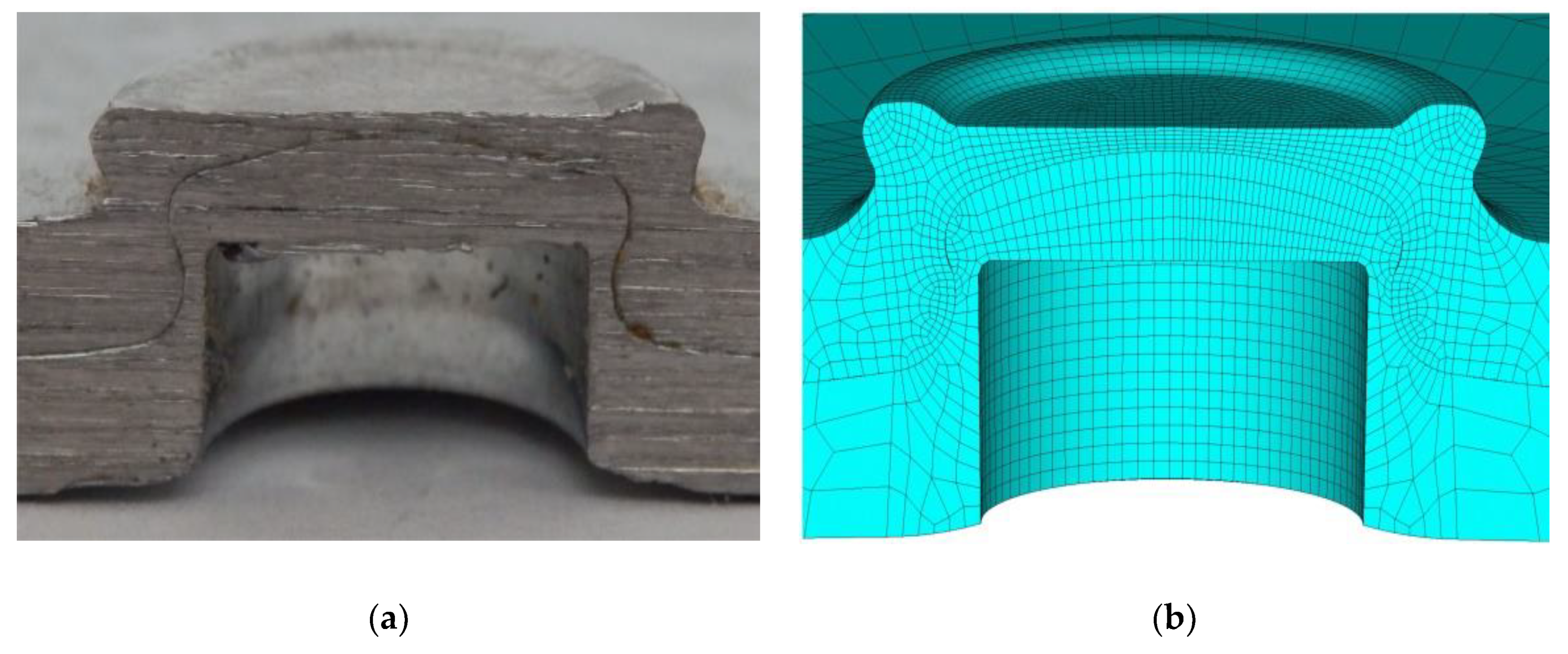
The real geometry of the cross-section was compared with the results of the numerical analysis of the clinch connection development process. In the first step, we considered a deformed mesh from the numerical model (
Figure 1) of the pressing process. Excessive deformation (bevelling) occurred in many volume components, preventing the possibility of further usage of the final-component network. As a result, it was necessary to find another solution based on the new numerical model prepared in ANSYS software [
29] (
Figure 2). The discussed model brings new insights into the simulation of sample attachment in the jaws of the tear-off machine and into the load-carrying possibilities of the test.
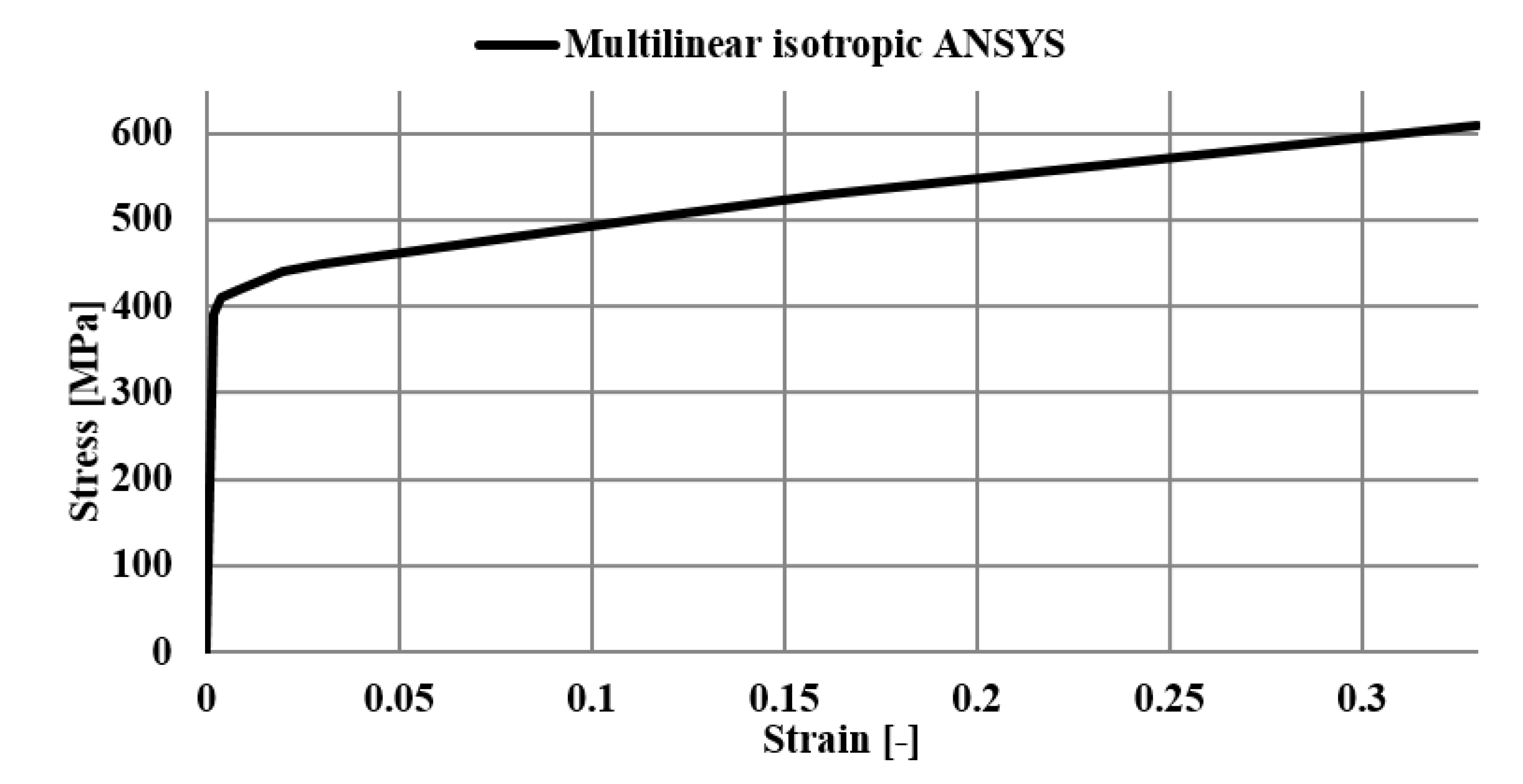
3. Verification of Material Parameters for Numerical Modelling
Physical experiments included verifications of material characteristics of the tested material. Tested samples were made of material S390GD with a yield point of 390 MPa. A series of such tests were carried out to verify the material and its yield points. According to the steel manufacturer’s certificate, the Poisson’s constant was 0.3. The parameters of the supplied steel have been checked, and their results have been published, for example, in [
17,
27]. Testing was conducted on standard bodies designed for tensile tests (see
Figure 3).
The model prepared in the ANSYS software was based on isoparametric finite elements with identical dimensions to the sample size. In
Figure 3, we can see the sample after rupture and the corresponding numerical model in ANSYS. It can be seen from this figure that the slope of the failure on the tested sample corresponds to the stress of the model. The deformation of the finite-element network is very similar to that of the actual deformation of the ruptured sample.
As mentioned before, the tested sample is an S390GD material with a yield strength of 390 MPa and a strength limit of approx. 460 MPa. On the colour scale in
Figure 3, it can be observed that values at the point of rupture are relatively close to the expected results. To define the real material model, the tensile test was subsequently modelled in ANSYS software [
29], on which the actual material model was built using an iteration method.
Figure 4 shows the resulting multilinear material model that was used in both models—the numerical model of the clinch connection tensile test and the evaluation numerical model of the conducted tensile test.
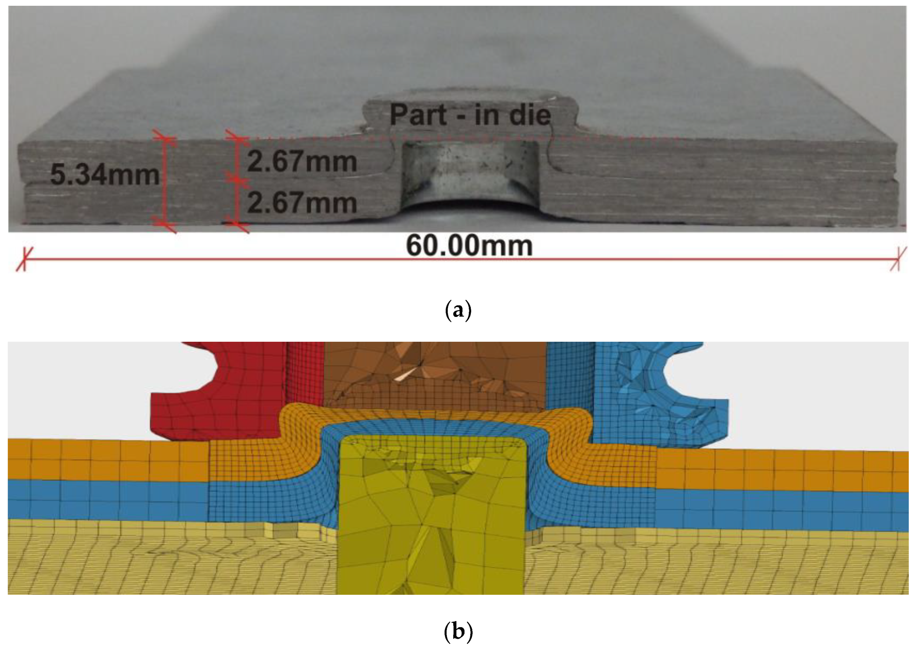
4. Tensile Test Setup and Numerical Model
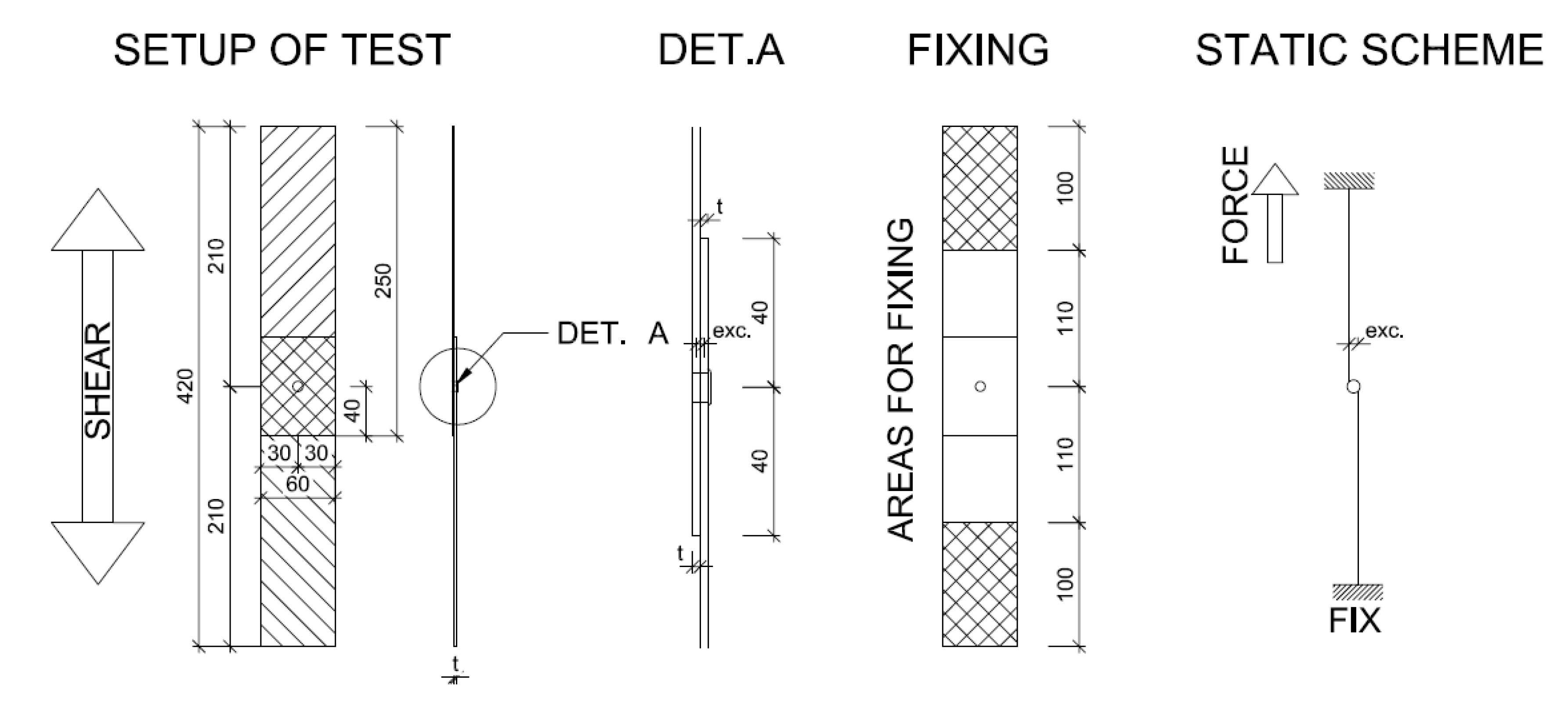
The setup of the physical tensile experiment is illustrated in
Figure 5. The thickness of the basic material is 2.67 mm. Clinch joint geometry is formed according to the cross-section of several samples before testing, and their confrontation with numerical model results in LS-DYNA [
27].
The computing model was prepared in an ANSYS system corresponding to a full scale of the physical experiment. The model employed volume elements SOLID186, which offer a great number of internal nodes. Exposed points modelled with 0.15 mm mesh size were then increased into a larger mesh size (see
Figure 6). The primary intention was to use the finite-element network created in the clinching process, even with the acceptance of the tension after relaxation. Nevertheless, some finite elements in the clinching process were damaged to the extent that they could not meet the conditions of reliable calculation. Residual tension from the clinching process did not play an essential role in further analysis.
The geometry was hence created from cross-sections of physical samples by their transformation to computer-aided design (CAD) for numerical analysis needs. Boundary conditions were specified in the numerical model according to the setup in
Figure 5. On one side, the sample was firmly fixed at the length of 100 mm, corresponding to fastening in the pressing machine. On the other side, the sample was also fixed but had an additional displacement in the nodes in the pressure machine movement direction. The numerical model was materially, structurally, and geometrically nonlinear. Contacts were created between all surfaces considered to be in mutual interaction. There was a clear goal to imitate the real sample so that its behaviour and geometry were as similar as possible. This approach can remove several deficiencies of the model, and the subsequent comparison can be satisfactorily accepted.
The material model was based on knowledge and was defined as being multilinear. The load was applied to the model in several steps, and a special load state was created to simulate slipping, in which the rigidity of the sample attachment for the movement section, which was 0.75 mm long, was reduced. This precondition was incurred based on physical experiments in which the sample was firmly fixed, in some cases after partial movement of the pressure head. The numerical model was conceived as a mathematical model without destruction, and deformation during load application was monitored to predict the potential points of joint failure. Important model parameters are listed in
Table 1.
5. Comparison of Results
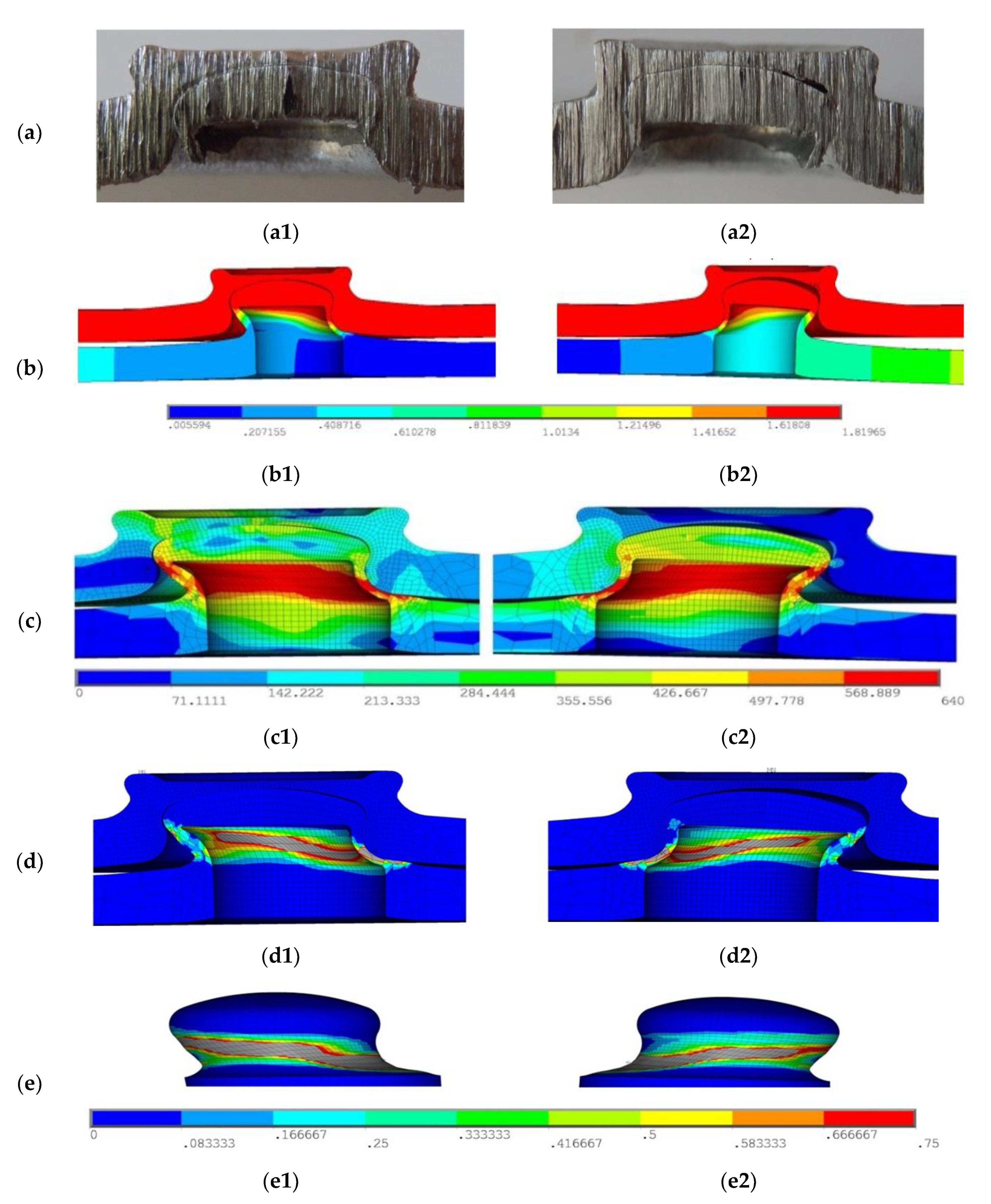
The physical experiment was considered as a tensile test. The testing procedure was completed for the destruction mechanism. Seven samples were tested in the laboratory, and the relations between the force and deformation were monitored. Typical joint deformations after the test are shown in
Figure 7.
We can see the cross-section of the joint (a1, a2), the deformation (b1, b2), the tension von Mises stress (c1, c2), and the inside (d1, d2) and outside (e1, e2) plastic deformation. The physical experiment was influenced mainly by the fixing method in the tearing press. In certain samples, slight slipping was experienced in press jaws during physical testing, followed by the deformation modes that can be seen in
Figure 7(a2).
As a result, it is necessary to look at the results from two viewpoints, first considering the samples and results with slippage in the jaws (
Figure 7(a1,b1,c1,d1,e1)) and then considering the samples and results without this effect (
Figure 7(a2,b2,c2,d2,e2)). The numerical model was considered for two different possibilities.
The first variant of the numerical model was simulated without slippage in the press jaws, and no undesirable extraction at the bottom part of the joint occurred. The trend of the load course and resulting force is very similar to that of the physical experiment. Numerical calculation of the first variant showed rigidity in the first section. In the numerical model, the same force as for the physical experiment could not be reached.
At the deformation of 1.50 mm, joint rigidity started to decline, and thus excessive plasticity of the joint was initiated (see
Figure 7c,d). This predicted the points of the most probable joint destruction. It can be also seen that the so-called neck is the weakest part of the clinch connection, and the results of the numerical model have proven that the points of the actual joint were successfully destructed.
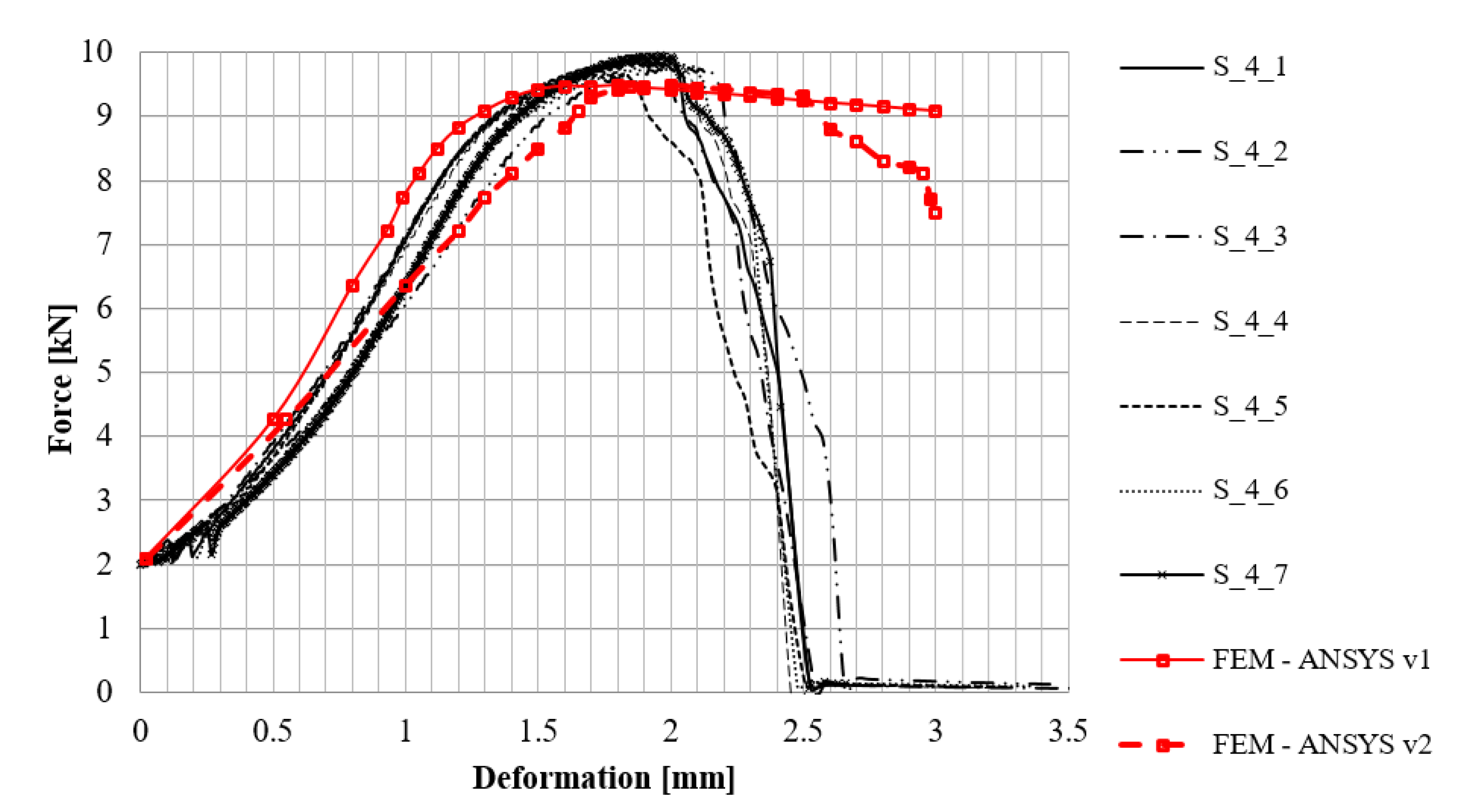
In the second variant, the model behaviour was different due to reduced rigidity at the attachment point (press jaws). In the physical experiment, slipping at the beginning of the load application occurred in some cases, and the bottom part of the joint was partially torn out in these samples. Values obtained from the course of the test for all samples are graphically displayed in
Figure 8.
Maximum force achieved in testing was 9.80 kN at the movement of 2.00 mm. The sample behaved linearly up to 7.50 kN when the respective deformation was 1.10 mm. It is apparent from the diagram that the trend between the physical experiment and the numerical model is identical. Comparing the results of Variant 1 and Variant 2 of the ANSYS model, there is a relatively large difference in force values before the deformation of about 2 mm was achieved.
The resulting forces from the two variants are, however, very similar, and the slight tear-off of the bottom parts was almost identical.
Figure 8 shows declined local rigidity for Variant 2. This may have caused the gradual tear-off of the bottom part. The edge of the bottom joint part, arched in the upper part, helped resist and prevent complete joint tear-off based on the friction scheme.
6. Discussion
This article deals with problems of clinch connection testing and its numerical modelling in an ANSYS system. Based on performed physical experiments, a destruction mode was determined at the weakest point of the clinch joint, the so-called neck. The numerical model was prepared based on data from previous research, following the development process of clinch connection.
Figure 1 and
Figure 2 show the comparison among the original numerical model in the LS-Dyna software, the photo of the sample cross-section at the joint, and the new model simulated by the ANSYS software. Tensile tests were performed to identify material characteristics of the tested material, and the acquired data were used in the numerical analysis under the form of a multilinear material model.
The actual results of the physical experiments are very similar to those of the numerical model. There are only slight differences between the models caused by inaccuracy in the attachment, some microscopic material defects, and other noninfluential facts. The article also contains a description of the acquisition and use of the model of material properties for verification.
The third part of this article summarises the knowledge of the numerical modelling of the problem. The discussed model brings new insights into the simulation of sample attachment in the jaws of the tear-off machine and into the load-carrying possibilities of the test. Finally, the results of the models and tests are compared.
Figure 7 provides a graphical understanding of the deformation of a joint after the tensile test, revealing that the numerical model can simulate the behaviour of the clinching joint.
The model also allowed us to determine the specific voltage values at all points in the joint. Two variants of behaviour were observed, depending on whether the specimen had slipped from the jaws or not. This refers to the results of the relationship between deformation and tensile force.


