1. Introduction
Modern construction industry focuses on the rational design of the sustainable building. The challenges of recent sustainable development require a reliable solution, which, in many cases, is characterized by multiple conflicting criteria [
1,
2]. Calculating floor settlements is a common task for structural designers [
3,
4]. The accuracy of the problem solving depends on the design procedure chosen [
5,
6,
7], conditions of a construction site [
8], aims and importance of the problem to decision-makers [
9]. Results can be very accurate, but for the minimum floor area. Besides, the results may cover a large area of the slab, but with much less accuracy. The decision-makers should take into account that the project’s life cycle conditions are changing [
10]. The sustainability of structures is highly dependent on design decisions [
11,
12]. Decision-makers need an integrated approach deploying complex support conditions on the ground floor to simplify computational procedures, save computation time and costs, and at the same time, obtain sufficiently accurate results.
Structural design programs cost money, and many are not used to resolve specialized issues. Among such issues are tasks such as ground-supported slabs that are partly supported on the pile foundations of structures. This paper proposes a method for solving ground floor slab design issues using conventional design programs and obtain the required accuracy of the results, thus avoiding the need to acquire specialized geotechnical applications that often cannot be used to solve basic design tasks.
A sufficient variety of software is available for the analysis of soil-structure interaction. Some software is more suitable for geotechnical problem solving (Plaxis, SoilStructure, Geo5, Novo Tech software, and so), and others usually are used for structural analysis [
13] with the data obtained from the geotechnical study. As a rule, geotechnical software requires more computer resources and time. Besides, no comfortable output of data is generally available, which is necessary for the reinforcement calculation of the structure. The study aims to provide a fast and efficient way to describe the behavior of subgrade under the floor slabs using conventional structural design programs, and to obtain reliable calculation results.
The structural analysis software commonly models the soil by using subgrade reaction coefficients [
14]. Springs that represent the behavior of the subgrade reaction under load are the basis of the soil modeling. The most widely used relation between forces and deformations is linear because of the simplicity of the equations’ solution.
In general, the floor slab’s behavior depends on its load values [
3], the layout and stiffness of subgrade, the thickness of the RC (reinforced concrete) slab [
15,
16], and the characteristics of soils under the slab [
14,
17]. The contact pressure between floor slabs and soil is indeterminate. When compiling the calculation scheme for a ground slab on a deformable subgrade, one encounters two problems: the nature of the distribution of the reactive pressure under the floors and the variable load [
18,
19,
20]. The intensity of the reactive pressure under the slab depends on the subgrade settlements, slab deformation, and the type of the load. Settlements rely directly on the rigidity of subgrade and slab [
7,
21]. The ground slab basement is a heterogeneous material, and the deformation properties of it depend on many parameters and factors [
22,
23].
All the soil layers affect the calculation results. Theoretically, the thickness of the elastic half-space is unlimited. In reality, however, soil deformations decrease with deepening; only the topsoil layers will deform [
17]. Only a limited thickness of the soil is compacted, and only a layer of a certain thickness will deform. The layer thickness depends on the loading area and soil properties [
20,
24]. One solution is to assume that the modulus of deformation increases with increasing depth. Besides, different soil types have different properties and affect the calculation results differently. Problem-solvers must consider it in the calculations. In general, the size and layout of the load may vary [
23].
For this reason, designers must assess the changes in the load’s layout and size within certain limits in calculations. Usually, the upper layers are compacted. If it is impossible to compact, weak upper soils can be replaced and then compacted [
25,
26]. As alternatives to the soft soils’ replacement could be chemical stabilization of soils, reinforcing of soils with rigid inclusions [
17,
27] or use of piles as supports for RC slab on the ground [
28,
29,
30].
Ground floor settlement differences may occur, not only due to different soil compressibility but also due to inadequate support conditions [
21,
31]. Very often, the floor slabs laid on soil, and the columns and the walls’ foundations support them.
The settlement of floor slabs and columns or walls foundations differ from each other. The pile foundations’ settlements are relatively small [
32]. Thus, the settlements of the floor slab above the foundation piles will be very small, while in other places, the floor slab sinks more [
33,
34].
As a result, the settlements of the floor slab differ significantly and may not meet the requirements for flatness. In such a situation, the designers must reduce settlements of the most deformed parts of the floor, or increase the settlements of parts above the columns or walls’ foundations. Settlements can be reduced by replacing weak soils, using chemical stabilization, or reinforcing the soil with rigid inserts. Another way is to deepen the pile foundation grid to the required level to ensure a sufficient magnitude of deformation of the floor slabs above the pile foundation grid. Reduced soil deformation and a deepened foundation piles’ grid also used together are useful to achieve a level of smoothness that meets tolerance requirements. Another possible way is to support the floor slab on the piles [
28]. In this case, the settlements of the slab significantly reduced, and the differences between relatively small settlements would not exceed limit values. The slab must be sufficiently thick and heavily reinforced. Moreover, a large number of piles may be needed. Therefore, such a method is expensive and not widely used when other solutions are possible.
Joints in the industrial floors are necessary. The calculation scheme divides the floor slab into segments according to the floor joints’ location. The size of these segments is limited. The purpose of joints is to release tensile stresses caused by drying shrinkage and temperature changes inside the slab as well as to provide breaks in the construction process. Therefore, the number and type of joints depend on the floor construction methods.
RC ground slab must satisfy the strength and the flatness tolerance requirements [
3,
4].
Thus, when designing industrial floors, there is a significant problem of how to evaluate the stiffness of subgrade and piles with the required accuracy, moreover, to do that with widely used structural computing applications.
The article provides analysis of two FEM-based methods: the Plaxis 3D and the Scad. For the Plaxis 3D, it is a large-scale computational task. This method models all soil layers based to their characteristics. Meanwhile, elasticity characteristics describe supports in the Scad. These elastic supports represent the deformations of the underlying soils. Such a way significantly speeds up and simplifies calculations.
In the paper, the proposed method allows to optimize design time, efficient use of computer resources, piles’ test data or obtained stiffness coefficients of the piles. This approach is tested on the practical case study.
2. Materials and Methods
Independently of soils’ situation, RC ground slab must satisfy the strength and the flatness tolerance requirements. The flatness tolerance requirements are especially crucial if lift trucks will be in use. If the slab does not meet flatness requirements, lift trucks can overturn. Therefore, during the design of the RC ground slab, the evaluation of the settlements of the subgrade is essential. The tolerance requirements depend on the type of lift trucks. The conditions, according to DIN 15185 [
4], are presented in
Table 1 and
Table 2.
When the slab subgrade is stiffer, the settlements are smaller, and the ground floor reinforcement is less intense. If the subgrade is more deformable, especially when the slab’s areas are loaded differently, the slab sits unevenly and needs more intensive reinforcement. In regions where pile foundation grillages decrease settlements of some parts of the slab, reinforcement may be particularly intense, and the differences of settlements between slab areas could hardly satisfy flatness requirements (
Table 1 and
Table 2).
The ground floor thickening is applicable as a critical solution to reducing the differences of the ground slab settlement but could be a quite expensive solution.
There are two main theories to model soil behavior: elastic half-space and subgrade reaction. When using the elastic half-space method, the equations of the elasticity theory apply. The surface deforms, not only directly at places of added load, but also nearby. The main parameter of the ground deformability is the soil elasticity modulus E (MPa). The elasticity modulus can be determined by testing soil samples in the laboratory (odometer, triaxial test), directly (plate load test, Ménard pressuremeter test) or indirectly (cone penetration test, standard penetration test) in situ.
The subgrade reaction (known as Winkler) theory states that the settlement of surface
s is proportional to the applied pressure
p [
35]:
where
Cs (MPa/m) is the subgrade reaction coefficient.
The settlement of a surface point depends only on the pressure added at that point. The estimation of the values of the subgrade reaction coefficient
Cs is one of the most complex problems in geotechnical engineering. This coefficient is not just an index that characterizes the soil properties; it also depends on the subgrade loading scheme, foundation geometry, depth, and size [
36,
37].
In addition to other factors, the numerical value of the subgrade modulus correlates to the soil elasticity modulus
E. The theory of elasticity simply explains the subgrade reaction coefficient. The elastic settlement
s of a flexible footing with the dimensions
l ×
b (
l >
b) is equal to:
where
q is the footing pressure;
ν—Poisson’s ratio;
Is—the influence factor depending on rigidity, the shape, and
l/
b ratio of the footing.
The Equation (2) can be written as follows:
where
ks is subgrade stiffness coefficient.
The soil is infinitely deep, and the soil elasticity modulus is assumed constant. The deformation will be smaller, assuming that compressed layer is of limited thickness. An additional factor can be introduced into the evaluation when compressing a layer of finite thickness [
16].
The concept of the subgrade reaction coefficient has been presented in technical literature by many researchers, including [
6,
31,
37].
The most commonly used is the one-parameter subgrade reaction coefficient. However, also, two-parameter settings were proposed [
38] as well as the layered half-space model [
5].
The two-parameter theory uses the subgrade reaction coefficients
C1 (a compression ratio) and
C2 (a shear ratio), as depicted in
Figure 1:
According to [
39], the subgrade reaction coefficients for two-parameter models for layered soil are as follows:
where
hi is the thickness of soil layer
i;
Ei is the modulus of deformation of layer
i.
Equation (11) express the modulus of the shear deformation
Gi of layer
i.
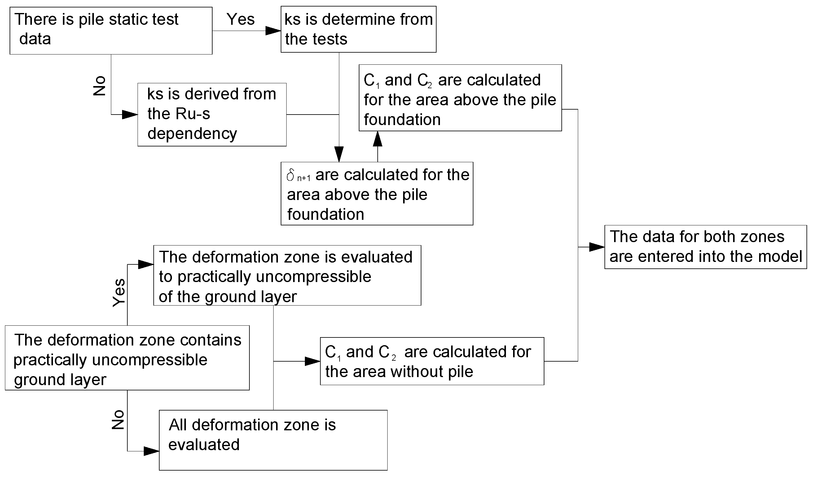
However, when evaluating the reaction coefficients of the layer above the pile cap, a different situation arises. There is soil deformation between the ground slab’s raft and the bottom and the settlement of the pile foundation due to additional loads. Designers could evaluate these deformations separately.
A designer could calculate the value of settlement
δ for soil between the pile cap and floor slab using formula (8). The piles’ foundation settlement is calculated under the assumption that spring is representing the pile’s behavior. The settlement of pile when used as the pile stiffness coefficient
ks is:
where
A is the area of the raft;
n the number of piles;
σsz—distributed load on a pile cap;
ks is the pile stiffness according to pile static tests and the secant point on the Weibull curve. It is equal to the spring constant
Kv0.33 of the model, and this quantity represents the pile stiffness under Serviceability Limit State conditions [
28]:
where
Kv0.33 is dimensionless pile stiffness;
D—pile diameter;
Ru—ultimate pile bearing capacity (or asymptotic ultimate bearing resistance
Rcau values).
Then the Equation (10) in the region above the pile cap must be changed to:
Using the above-presented procedure obtained stiffness coefficient, the increase of subgrade stiffness in the pile cap area is modeled. In this way, structural applications are proper to analyze slabs on the elastic subgrade and, at the same time, asses the influence of the caps of the piles.
Figure 2 shows a flow chart for the calculation procedure.
3. Practical Application of Proposed Model
The real case study in this section is based on the design task of a large logistics center. It shows how to use the proposed stiffness estimation method to calculate industrial ground slab deformations and internal forces using the widely used structural design program. The same task is solved with the specialized Plaxis 3D software.
A variety of RC ground slab settlements were calculated for the logistic center. Self-weight, uniformly distributed, and concentrated loads from shelving supports were applied to the slab model.
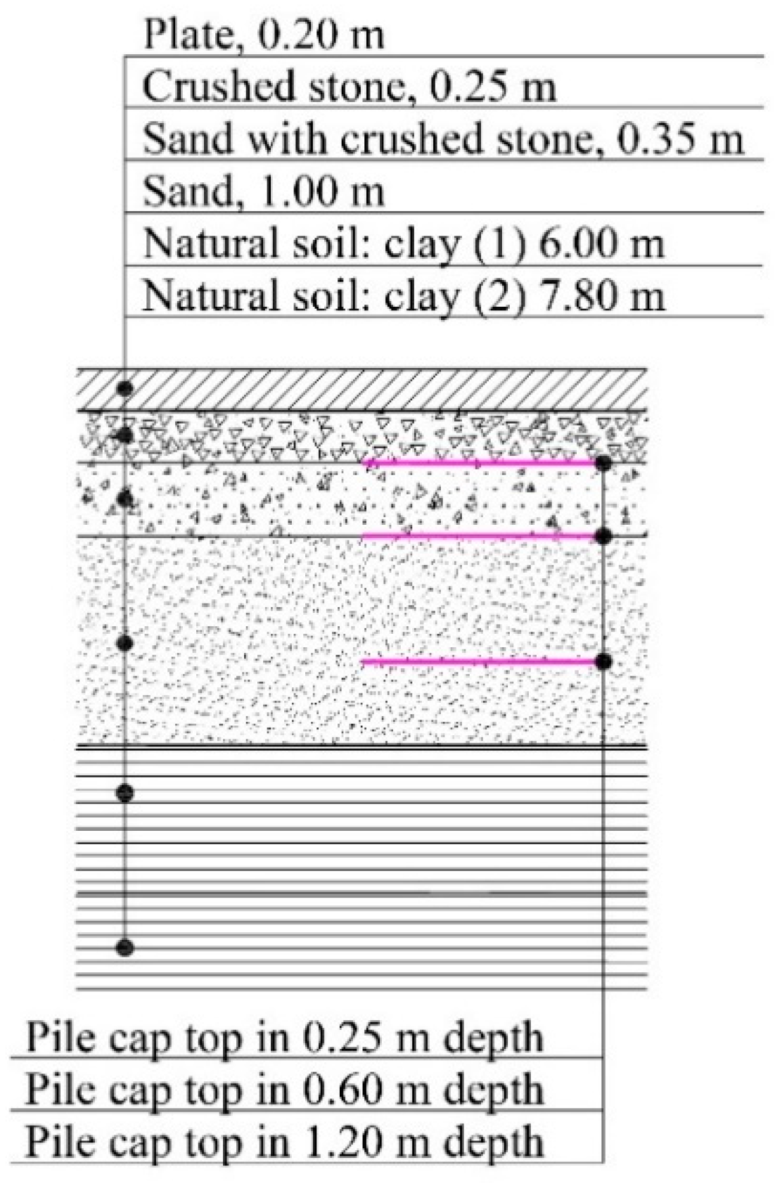
Five ground layers are the ground slab’s basis.
Figure 3 and
Table 3 present subgrade cross-section and characteristics of the layers. All the characteristics of the soil layers are taken from the geological report of the site. Only for crushed stone, sand with crushed stone, and sand minimal cohesion value of 1 kPa are accepted. This is because the FEM model does not allow to determine the shear strength of the soil without providing adhesion. Otherwise, the stiffness matrix is not compound, and the FEM model has no solution.
Comparative calculations for three depths of the pile cap were performed.
Figure 3 shows depths (0.25, 0.60, and 1.2 m) from the ground slab’s bottom o to the pile cap’s top.
The RC ground slab’s parameters used in the calculation are as follows: the thickness of the RC slab—0.2 m; the weight density of the RC slab—25 kN/m3; the modulus of the RC slab deformation—31 GPa.
The task is to calculate the settlements of an 0.2 m thick RC ground floor slab loaded by uniformly distributed and concentrated forces (
Figure 4).
The characteristic uniformly distributed load of the slab was 50 kN/m
2 (this value without self-weight of the slab). This load was applied to all the surfaces of the RC slab. For values and layout of concentrated loads from shelving supports, see
Figure 4. The following distribution and magnitude of the loads were specified in the design task of the analyzed logistics center.
For ground slab analysis, two software packages were used: Plaxis 3D Foundation v.1 (Plaxis 3D)—geotechnical analysis program and Scad 11.7 (Scad)—structural analysis program. Plaxis 3D has the possibility of a direct analysis of soil behavior. Scad accepts soil behavior as a response of the springs. When using spring models, proper evaluation of stiffness of the soils and the changes of soils’ stiffness above the pile foundations is quite complicated. At the same time, these structural analysis programs could be used for the simplified fast structural design of the floor slabs.
3.1. Calculations of the Slab with Plaxis 3D
The Mohr-Coulomb model was used during the analysis of the logistic center-ground slab settlements. The yield surface of this model is an extension of the Coulomb’s friction law to the general states of stress (the Manual of Plaxis 3D).
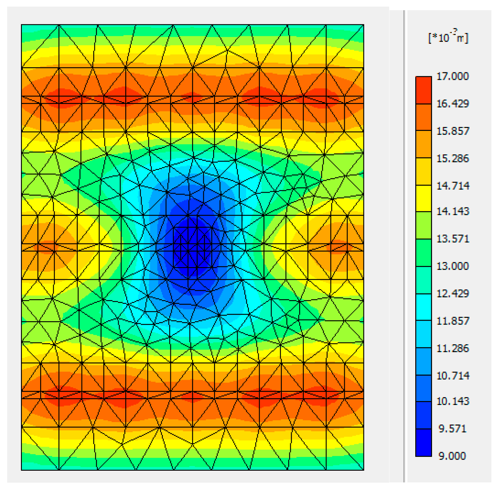
Figure 5 shows the settlement distribution of the modeled fragment “A” of the RC slab when the pile cap is in-depth of 1.20 m.
The depth of the pile cap affects the settlements of the slab. The settlements will be uniform if, above the pile cap, the floor subgrade structure is thicker. It can be seen from the settlements chart (
Figure 6) in section A-A (layout in
Figure 4a) that the pile cap’s depth affects the plate settlements. Slab’s settlements above the foundation when subgrade is 0.25 m, 0.60 m, and 1.20 m thickness, are equal respectively to −4.74 mm, −6.06 mm, and −8.99 mm. So, when the pile cap is deeper, the slab’s settlements can be unified.
3.2. Calculations of the Slab Using FEM (Scad) Program
For the slab calculations based on Eurocode 2 [
40], a two-parameter model was used.
The base under the floor is divided into two zones: a region with no pile foundation; a region over the pile cap.
During the calculation, the pile stiffness coefficient
ks = 81 MN/m [
28] was used to predict the subgrade reaction coefficients in the zone above the pile cap. Other parameters were the same as in the calculation with Plaxis 3D.
The deformable soil layer outside the pile cap is assumed to be 10.0 m. Affected by the floor weight (4.8 kPa) and storage load (50 kPa), considering only vertical deflection, the floor slab settlement will be 17.47 mm. The subgrade reaction coefficient C1 for the layer outside the pile cap will be 3137 kN/m3. The floor weight (4.8 kPa) and the storage load (50 kPa) 1.20 m, affect the thickness of the layer above the pile cap. The layer compression will be 1.00 mm.
The pile foundation will be affected by slab weight, storage, and pile cap loads. The pile foundation settlement is calculated under the assumption that the spring is used instead of a pile with the stiffness coefficient equal to
ks = 81,000 kN/m. The deformations of the floor plate are calculated only from the additional loads—the weight of the floor slab and storage load. According to [
5], the pile foundation settlement will be only 0.33 mm.
The subgrade reaction coefficient C2 for the layer above the pile cap will be 41,221 kN/m3.
The subgrade reaction coefficient for zone outside the pile cap can be calculated by applying Equation (7), where
δΣ = 0.3188·10
−3 m
3/kN and for the layers’ base
δn+1 = 0.
Table 4 shows the calculated values.
In the zone above the pile cap, only the three upper layers are evaluated. For the pile foundation, according to Equation (13), δn+1 = 6.0494·10−6 m3/kN.
The values of the subgrade reaction coefficients are presented in
Table 5.
Figure 7 shows the distribution of the settlements of the modeled fragment “A” of the slab when the pile cap is in-depth of 1.20 m.
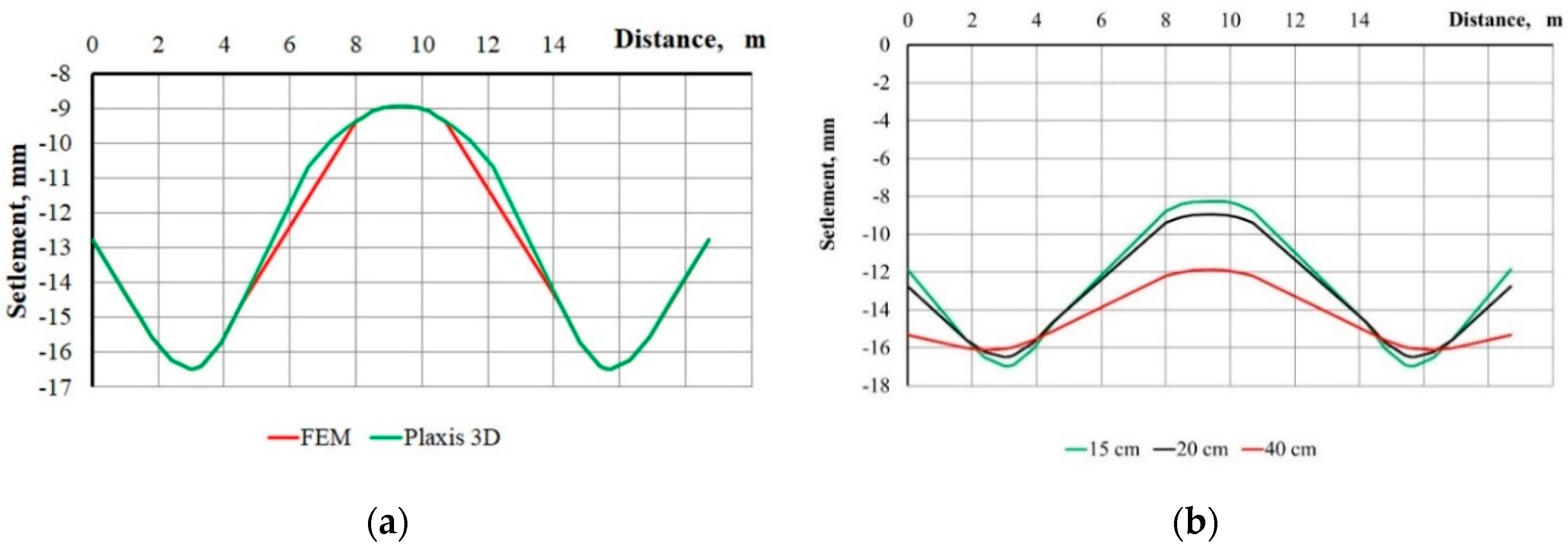
The presented slab’s settlements charts (see
Figure 5 and
Figure 7) of the fragment “A” show that settlements’ distribution and the values obtained using the FEM program and Plaxis3D are practically identical. Additionally, it can be seen by comparing settlements in section A-A with a 1.20 m thick layer of soil above the pile cap (
Figure 8a). These results are obtained when the thickness of the RC slab is 0.2 m. The maximum and minimum settlements’ values are identical.
The influence of the slab thickness also affects its deformation. It can be seen from the graphs given in
Figure 8b, which presents the results of calculations when the pile cap is at a depth of 1.2 m below the floor slab, and the thickness of the slab is either equal to 0.15 m, 0.20 m, or 0.40 m.
The rigidity of the floor slab (changing the slab thickness) affects the deformations of the slab. However, the amount of concrete will increase significantly. The maximum and minimum settlements in the cross-section A-A, depending on the thickness of the slab, are given in
Table 6.
By increasing the thickness of the slab, its settlement is more uniform. Still, the maximum settlements decrease not significantly. There is a slight difference in the minimal settlement: as the slab thickness increases from 0.15 to 0.40 m, the minimal value of settlement decreases up to 43 per cent.
4. Results and Conclusions
The paper proposes a method of ground floor slab design using conventional structural design programs. This efficient calculation method makes it possible to avoid the need for specialized geotechnical applications. The results of the calculations show that the method proposed in the article gave the required accuracy, and the calculation procedure is quite fast and uncomplicated.
Different ground slab settlements could be caused not only by the loads and the characteristics of subjacent ground layers but also by the various support conditions. The existence of pile foundations under the ground slab could significantly increase the stiffness of a subgrade in a particular area and reduces settlements of the ground slab around them. This effect is especially evident in the areas where the main building columns are on the group of piles supported. In this case, the subgrade above the pile cap is stiff, and settlements of the slab above are small. At that time, the parts of the slab away from the stiff subgrade will settle more, and differences in settlements occur. The increased settlements of the less deformed parts of the slab will reduce the settlement differences to a certain level, and the slab flatness will not exceed the permissible requirements.
The calculation results show that the pile cap’s descent into deeper soil layers allows achieving acceptable differences of settlements of the floor slab. In this case, the calculation of the subgrade reaction coefficient under RC slab should assess the soil layer thickness and pile settlements.
In the case of the calculation of large dimensional logistic center floor settlements, it is recommended to use the subgrade reaction coefficient with two parameters. The two-parameter subgrade coefficient can successfully supplement the modeling of the base using finite elements. The settlement distribution and values using the FEM program and Plaxis 3D software were practically identical. This proposed integrated engineering method reduces computational efforts and provides sufficiently accurate results.
The thickness of the ground slab directly affects the rigidity of the slab and changes the settlements. However, this method is not the most efficient one to use only to reduce and unify settlements of the slab because of the significant increase in materials consumption for the slab.

 ,
, 


