Article

Active Disturbance Rejection Control of Boiler Forced Draft System: A Data-Driven Practice

Key Laboratory of Energy Thermal Conversion and Control of Ministry of Education, School of Energy and Environment, Southeast University, Nanjing 210096, China
*
Author to whom correspondence should be addressed.
Sustainability 2020, 12(10), 4171; https://doi.org/10.3390/su12104171
Submission received: 4 April 2020 / Revised: 8 May 2020 / Accepted: 11 May 2020 / Published: 20 May 2020
(This article belongs to the Section Energy Sustainability)

Abstract

:
Boiler forced draft systems play a critical role in maintaining power plant safety and efficiency. However, their control is notoriously intractable in terms of modelling difficulty, multiple disturbances and severe noise. To this end, this paper develops a data-driven paradigm by combining some popular data analytics methods in both modelling and control. First, singular value decomposition (SVD) is utilized for data classification, which further cooperates with back propagation (BP) neural network to de-noise the measurements. Second, prediction error method (PEM) is used to analyze the historical data and identify the dynamic model, whose responses agree well with the actual plant data. Third, by estimating the lumped disturbances via the real-time data, active disturbance rejection control (ADRC) is employed to control the forced draft system, whose stability is analyzed in the frequency domain. Simulation results demonstrate the efficiency and superiority of the proposed method over proportional-integral-differential (PID) controller and model predictive controller, depicting a promising prospect in the future industry practice.

1. Introduction

At present, China’s power generation is still dominated by thermal power. Thermal power generation accounts for most of the total power generation in China. The amount of coal consumed each year accounts for half of the total energy consumption of the country. However, the combustion of coal produces a lot of carbon dioxide and other harmful gases, bringing serious pollution to the environment [1,2]. By operating a boiler combustion system, which is one of the most important production equipment in the thermal power plant, economically and efficiently, we can greatly save the coal consumption and achieve energy saving and emission reduction by the thermal power plant. The boiler combustion control system mainly includes three subsystems: a forced draft control system, induced draft control system and fuel control system [3]. The forced draft control system is mainly used to transport pulverized coal into the boiler and provide oxygen for boiler combustion. The induced air control system is mainly used to ensure the furnace negative pressure. The fuel control system is mainly used to change the amount of fuel entering the furnace according to the boiler instruction. Among them, the forced draft control system is in pursuit of the best air-coal ratio, (i.e., the air volume vs fuel injected into the boiler). In the best air-coal ratio state, the pulverized coal entering the furnace can be fully burned, leading to less emission of toxic gases like CO and heat loss in the production, which has great significance in energy conservation and emission reduction.
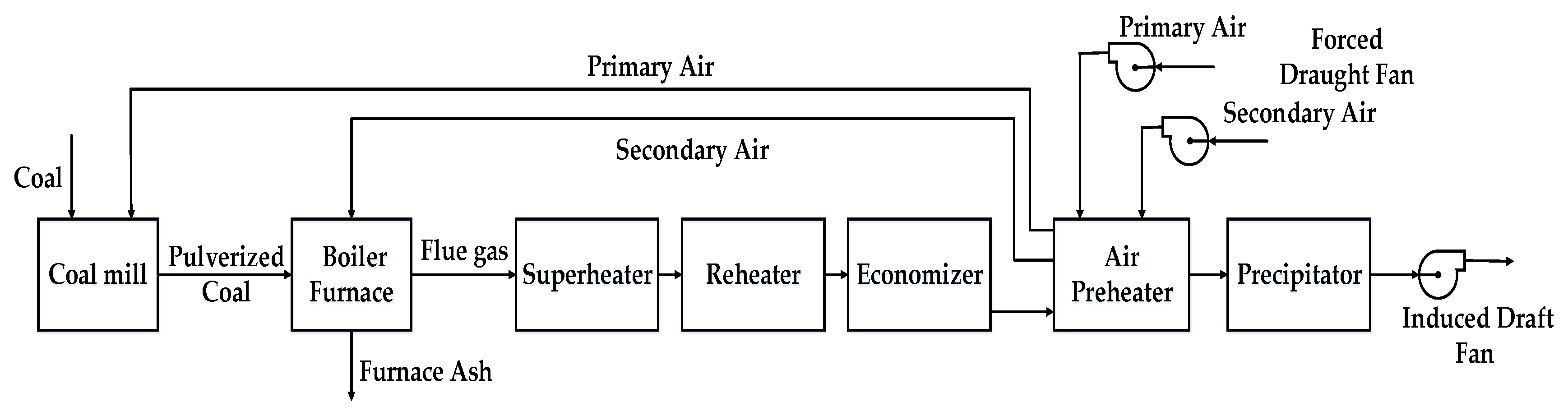
Combustion control is the most important aspect of boiler unit operation. The boiler combustion system is shown in Figure 1. The coal is crushed by the coal mill and blown into the boiler by the primary air. After the coal is burned in the boiler, the flue gas passes through the superheater, reheater, economizer and air preheater for heat exchange. Finally, the flue gas is discharged into the atmosphere.
For large-scale coal-fired boiler, combustion air distribution is a main aspect of operation control. Different boiler equipment and coal quality have the optimal air distribution mode. The air distribution mode directly affects the economy of the boiler unit operation. If the air volume is too small or the fuel distribution is not appropriate, the flame center of the furnace will be low and the fuel combustion rate will be poor, leading to low steam temperature and boiler thermal efficiency. If the air volume is too large, it will cause the flame center of the furnace to move up and reduce the residence time of the pulverized coal in the combustion area of the furnace, leading to the increase of the desuperheating water volume and mechanical incomplete combustion loss [3,4,5]. Therefore, unreasonable air distribution will affect the thermal efficiency of the boiler, the cycle efficiency of the unit and the economy of the unit operation.
For high-quality coal, if the primary air volume and secondary air volume are too low or the air distribution is not appropriate, it will cause early ignition and local reducing atmosphere in the furnace, resulting in burner damage and furnace slagging. For inferior coal and coal with low volatile content, excessive primary air volume will lead to boiler fire extinguishing and cause the combustion system to wear, affecting the stability and safety of the unit operation [3,4]. It can be seen that the rationality of boiler air distribution is the basis of unit operation economy and safety. With the higher requirements of automatic control for the units in operation, the automatic control of boiler combustion is a main content. The automatic control of combustion is basically achieved by the calculation of fuel quantity and air distribution volume and the correction of boiler oxygen content [3]. Therefore, it is necessary to require the boiler unit to have a reasonable and accurate air volume control system. Only in this way can the boiler combustion be controlled deeply and accurately, and the unit operation can be guaranteed to have a higher level of safety, stability and economy.
In the actual power units, the air volume is often controlled by forced draft fans. The dynamic characteristics of the forced draft system are affected by other disturbances such as boiler load, coal supply, oxygen content in the furnace, etc. In the measurement of air volume, the existing measurement methods and equipment are limited by science and technology. Therefore, the air volume measurement is not accurate and the sampled data of air volume and coal quantity have more disturbances and noises, which makes identification very difficult. In order to improve the accuracy of identification model and establish a more accurate model of air supply system, it is necessary to reduce noise and classify the data. With the development of big data technology, de-noising methods and data classification methods have many new developments and are widely used. De-noising methods include three-sigma rule [6], density-based spatial clustering of applications with noise (DBSCAN), singular value decomposition (SVD) [7,8,9,10] and so on. Data classification methods include k-means method, Gaussian mixture model method, k-nearest neighbor method [6], back propagation (BP) neural network [11,12,13,14], etc. As a widely used data de-noising method, SVD is applied in many fields of engineering. A newly reported reweighted SVD method uses periodic modulation intensity criterion to measure how influential the periodic impulses are in each signal component [7]. A novel SVD-based guided wave array signal processing approach is presented in [8] for relatively weak signals. Based on singular value decomposition package (SVDP), an extended SVDP and its fast computation for extracting the resonance band excited by bearing defect with distinguished performance is proposed in [9]. Online SVD for time-varying matrix is proposed in [10]. At the same time, as an advanced modeling method, BP neural network also has been applied in many industrial or non-industrial models. An adaptive Kalman filtering algorithm based on BP neural network was proposed for real-time exhaled breath analysis in [11]. In [12], an improved genetic algorithm (GA)–simulated annealing algorithm (SA)–BP (GASA-BP) prediction model was established by introducing an adaptive learning rate into the original BP neural network algorithm for predicting coal and gas outburst. A BP neural network with principal component analysis method was used to forecast the bio aerosol concentration in [13]. It presents in [14] an improved method BP neural network back analysis of in-situ stress field, based on the calculated results of multivariate linear regression analysis. From the above literature, it can be seen that SVD can accurately extract data and has excellent performance in industrial data noise reduction. For big data, BP neural network modeling method can be used in a lot of aspects, and the prediction and analysis are more accurate. However, most of the current data-driven practices in power plant industry are macro fuel consumption prediction, fault data classification, etc. In data processing before modelling, data-driven practices is rare. This paper attempts to use the data of the boiler forced draft system to improve the accuracy of the model. Therefore in this paper, a data classification method of united SVD data de-noising method and advanced BP neural network is proposed to classify the data and improve the accuracy of closed-loop simulation, which is based on the massive data resources provided by the big data platform of a fossil power generation group. SVD can effectively reduce unnecessary noise in data. Meanwhile, after noise reduction, BP neural networks can also effectively learn the properties of training data to classify field data.
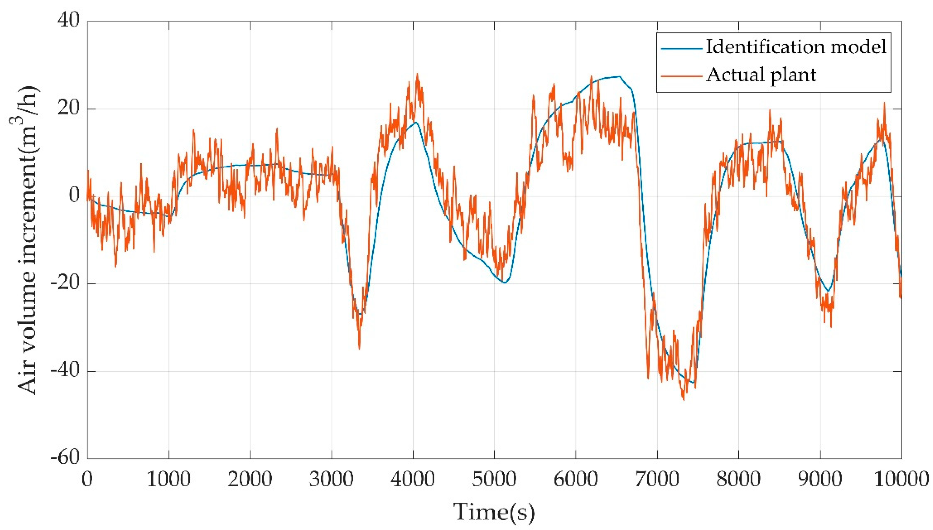
After classifying the data of air supply system, it is necessary to use the classified data to model forced draft control system. The forced draft control system is a single-input-single-output (SISO) system. The total air volume is controlled by the adjustable vane opening (AVO) of the forced draft fan, and associated with the coal quantity and the AVO of induced draft fan. For this system, the prediction error method (PEM) [15,16,17,18] is used in this paper for modeling using the classified data. As a mature modeling method, PEM has been verified on the reliability of modeling in various fields. In [15], a stabilized version of PEM, where a virtual controller stabilizes the prediction error, was introduced. A novel approach for the task of speech reverberation suppression in non-stationary (changing) acoustic environments was proposed based on weighted prediction error method in [16]. In [17], a separable prediction error method for robot identification was proposed considering the physical parameters as well as the noise model. It presented in [18] that a recursive prediction error method which can be applied on a model of any degree of complexity.
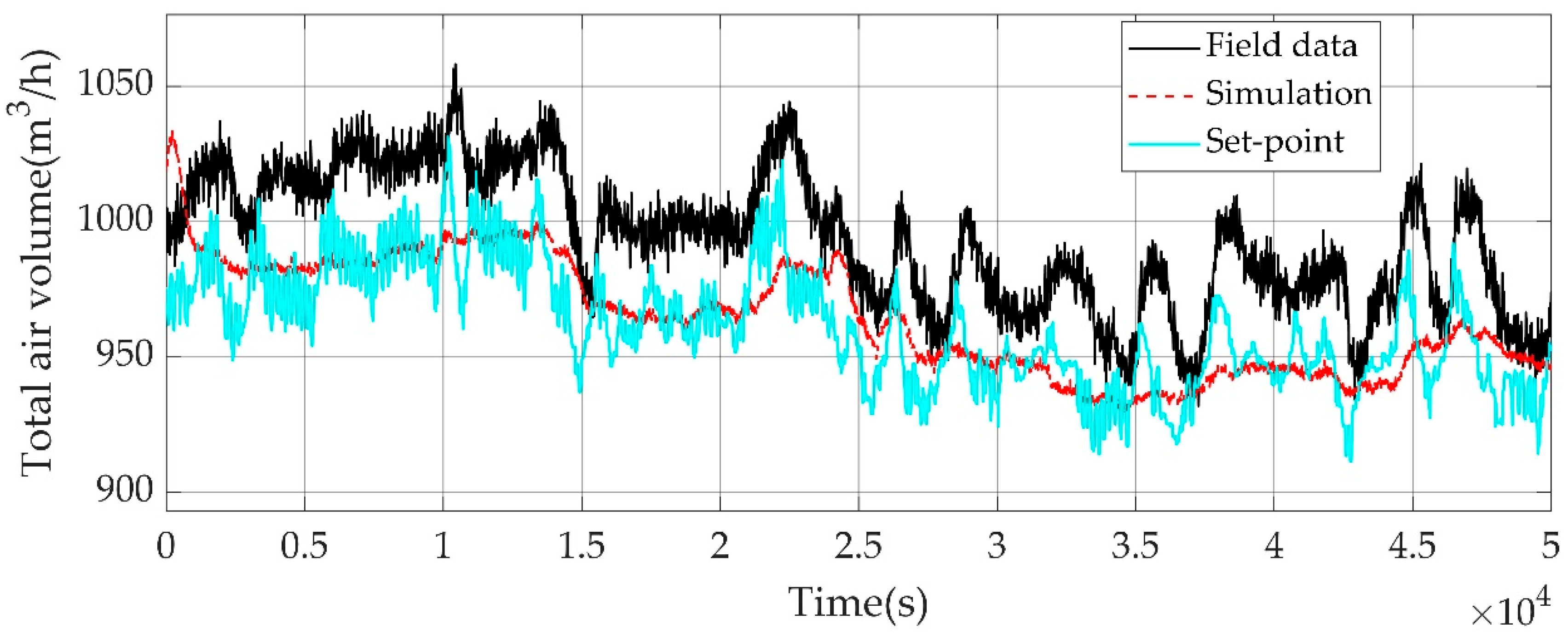
Based on the identified model and the actual proportional-integral-differential (PID) control strategy of the forced draft control system of a power plant in the city of Nanjing, Jiangsu Province, China, the closed-loop simulation system of forced draft control is established to verify the feasibility of the data classification method and the accuracy of the closed-loop identification model, and to study better control strategies. Since the forced draft control system is related to boiler combustion and coal supply, conventional PID control is difficult to overcome a lot of disturbances. When the load changes greatly, the conventional PID control cannot adapt to it as well as many other problems like large overshoot, long settling time and poor robustness, making it difficult to achieve satisfactory control effect. To solve these problems, some advanced control algorithms have been put forward such as active disturbance rejection control (ADRC) [19,20,21,22], model predictive control (MPC) [23,24,25,26], adaptive control and so on. Two robust control techniques estimating disturbances for small-scale unmanned helicopters: adaptive disturbance rejection control (ADRC) and disturbance observer based control (DOBC) are introduced and compared in [19]. In [20], ADRC was used in an open-cathode proton exchange membrane fuel cell (PEMFC), and extensive simulations demonstrated the uncertainty compensation ability of ADRC. It analyzed in [21] that the control mechanism from the perspective of the modified plant, which, in turn, would give guidance to parameter tuning of ADRC and a complete tuning procedure for ADRC was developed. The capability of ADRC was investigated in [22] in dealing with the nonlinear systems with multiple uncertainties and nonlinear measurement. As an advanced industrial control technology, MPC has been fully applied and developed. It considered in [23] that distributed model predictive control (DMPC) for the vibrations of smart tensegrity structures with input saturation. In order to optimize the energy production of an inertial sea wave energy converter (ISWEC), an original model predictive control was used in [24]. An adaptive model predictive control was developed in [25] to solve parameter uncertainty of hybrid energy storage systems. A MPC approach was also used for hydrogen circulation system of polymer electrolyte membrane fuel cell in [26]. Considering the strong disturbance-rejection ability of ADRC and good performance of MPC by using accurate identification model, they are studied in the forced draft control system respectively and compared with single PID control in this paper. Taking advantage of big data resource of power plants, this paper studies control strategy optimization on boiler forced draft system.
The purpose of the paper is to improve control performance of the boiler draft system in terms of fast command following which is critical for maintaining the best air-coal ratio. In pursuit of following the preset air-coal ratio tightly in operations of the combustion system, this paper proposed more effective modeling and control approaches on the boiler draft system. The main contributions of this paper are summarized as follows:
  • In order to establish an accurate model of the boiler forced draft system, a novel data classification method of united SVD data de-noising method and advanced BP neural network is proposed in this paper. This method can effectively reduce the noise, and reasonably screen the data for modelling.
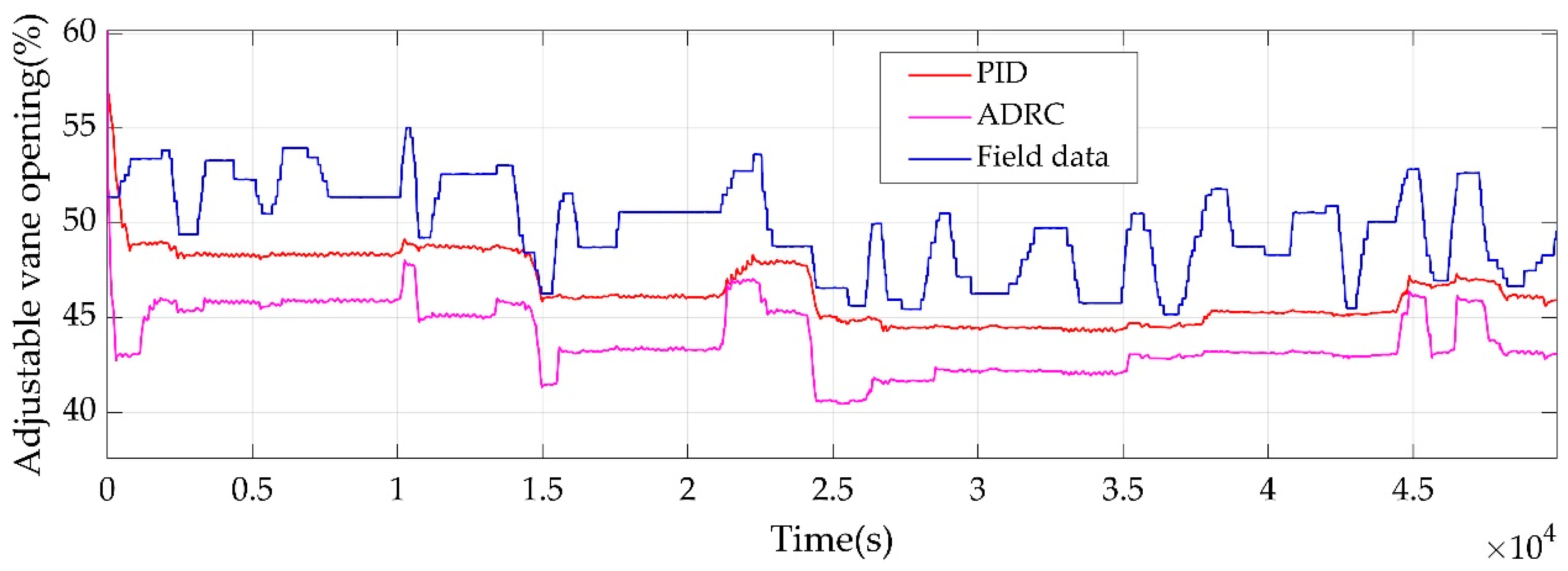
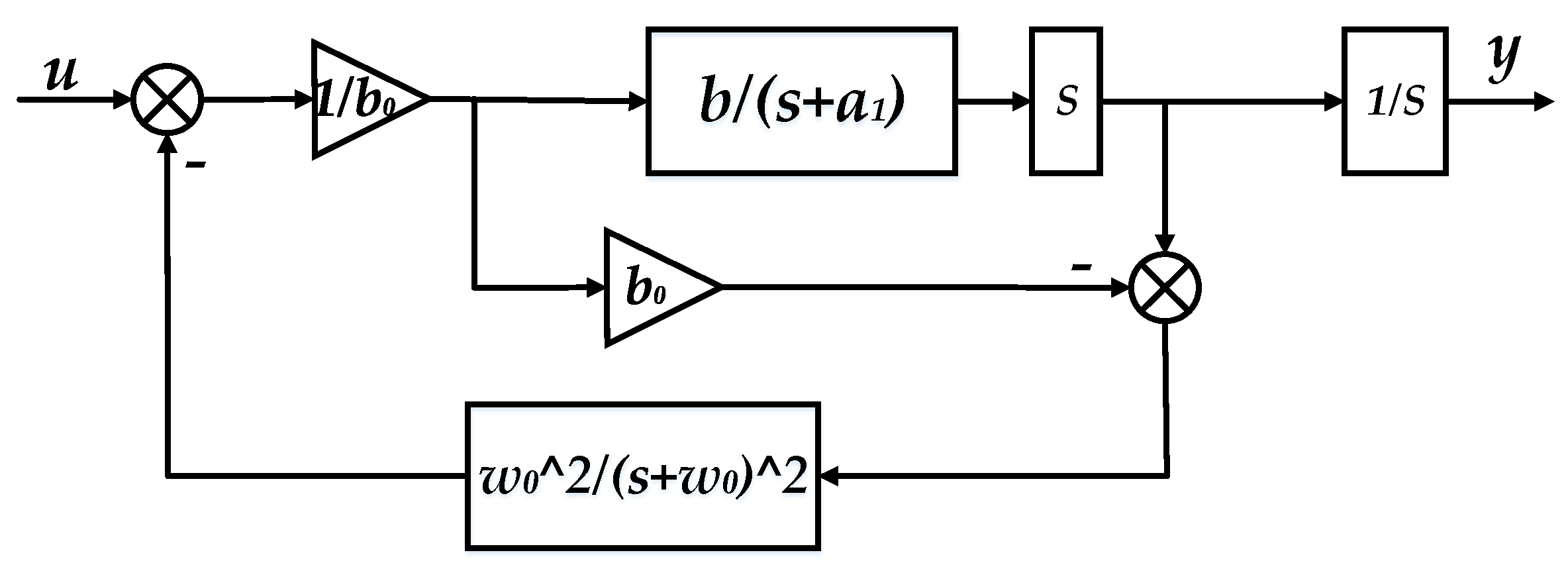
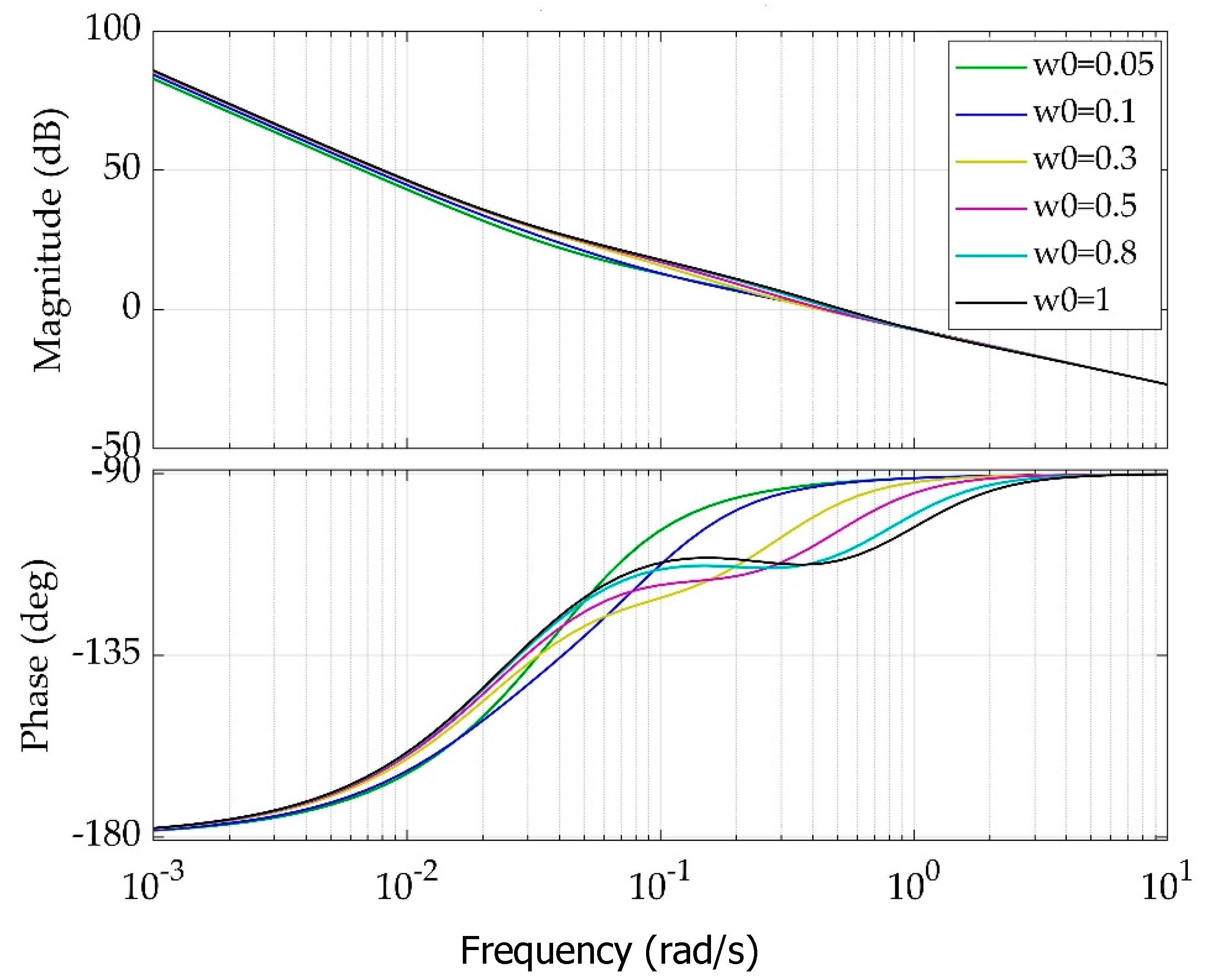
  • The advanced ADRC controller is designed for the boiler forced draft system and applied to the model. The stability of the ADRC control loop for boiler forced draft systems is analyzed in the frequency domain and its flexible stability margin is shown.
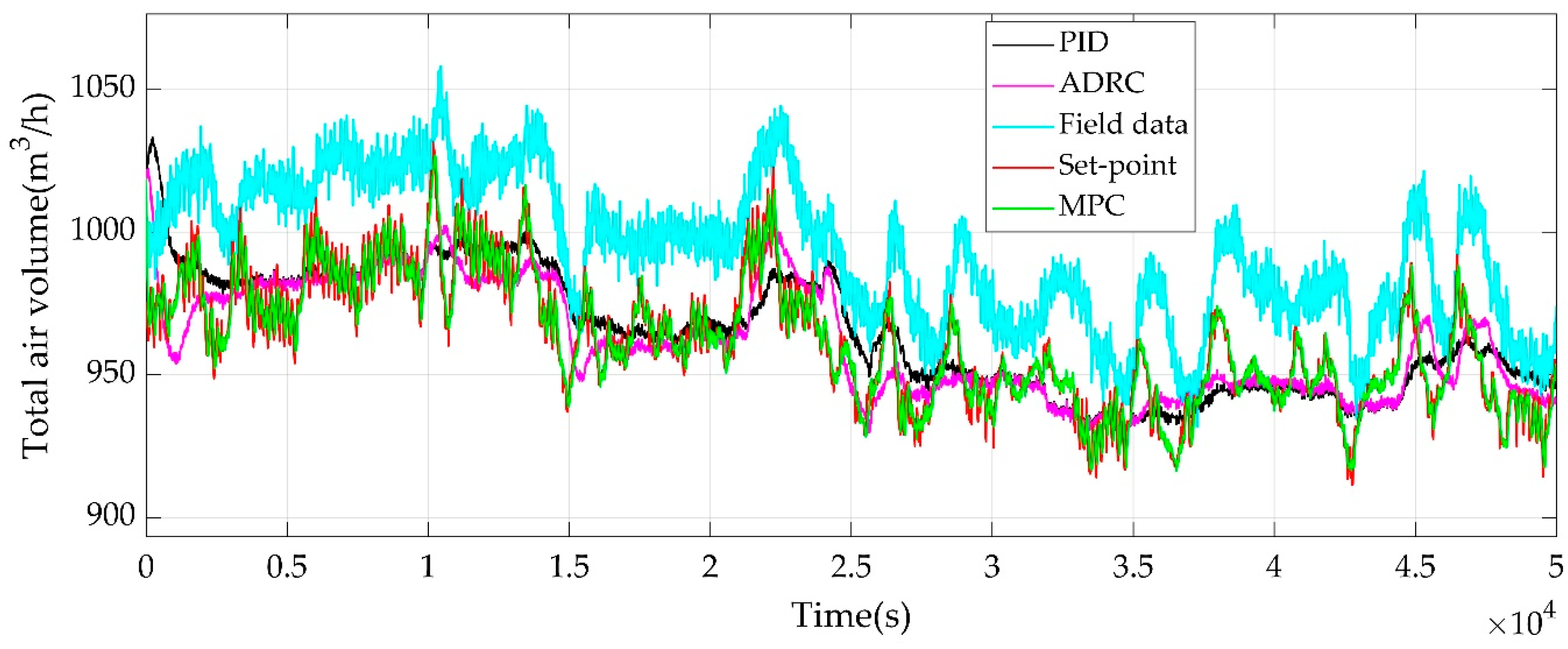
  • The good control performance of ADRC is proved by comparing with other control approaches including single MPC and PID and is also evaluated by comparing with the field data from the real control system.
The rest of the paper is organized as follows. In Section 2, the data classification method called SVD-BP is introduced for extracting identification data. In Section 3, the simulation system of boiler forced draft control is established for verifying closed-loop identification accuracy and for control study. In Section 4, the advanced control strategies of boiler forced draft control system are studied based on the closed-loop simulation system and compared with each other. Conclusions are drawn in Section 5.

2. Data Preprocessing

Because of the dynamic characteristics of the forced draft control system, the error of the air volume measurement strategy and equipment, and other unknown disturbance problems, the data of air volume and coal volume has great volatility. In order to establish an accurate model of the forced draft control system, it is necessary to reduce noise and classify the data. This paper performs noise reduction and classification based on field data from a big-data platform on a boiler forced draft control system in a power plant. First, the dynamic characteristics of the forced draft control system and the characteristics of data are analyzed. Second, SVD is used for filtering noisy data. Third, the BP neural network is used for the de-noised data to find the best identification data segment.

2.1. The Dynamic Characteristics of the Forced Draft Control System

In the forced draft control system, the air enters the boiler through the primary fan and the secondary fan. Before the air enters the boiler, it is heated by an air preheater to improve the boiler thermal efficiency. The role of primary air is to transport and dry pulverized coal, and to supply the air required for fuel combustion. The main process of primary air is that the air enters the primary fan the air preheater. After being heated by the air preheater, the air enters the coal mill. At the proper temperature and flow rate, the pulverized coal is dried by the primary air and transported through the pulverized coal pipeline to the burner nozzle to be injected into the furnace for combustion. The role of secondary air is to supply the oxygen required for fuel combustion. The secondary air directly enters the boiler after passing through the air preheater. The process flow diagram of the forced draft system is shown in 
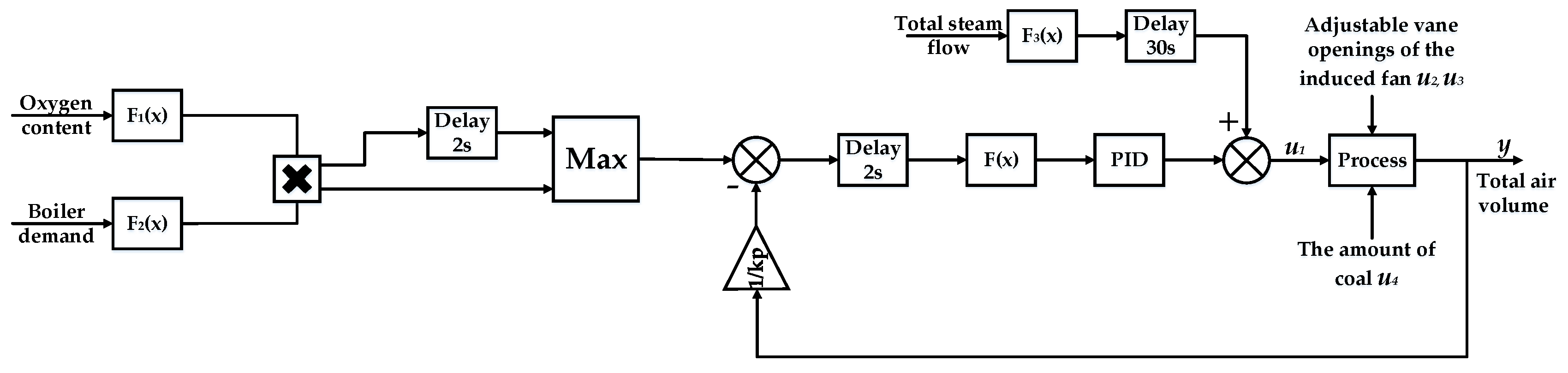
Figure 2, and the conventional control strategy of the forced draft system is shown in Figure 3.
Because the primary air flow depends on the primary air volume required by the combustion system and the amount of air leakage through the air preheater, we only need to control the secondary air volume to achieve the purpose of controlling the total air volume. Simultaneously, the set-point of the total air volume is calculated based on the oxygen content of the flue gas. It can be seen from Figure 2 that the total air volume is determined by the amount of coal, the AVO of the forced fan and the induced fan. Thus the inputs of the model can be chosen as the AVOs of the forced fan, the induced fan A, B and the amount of coal, denoted as u1, u2, u3 and u4 in Figure 3. The output of the model is the total air volume, denoted as y in 
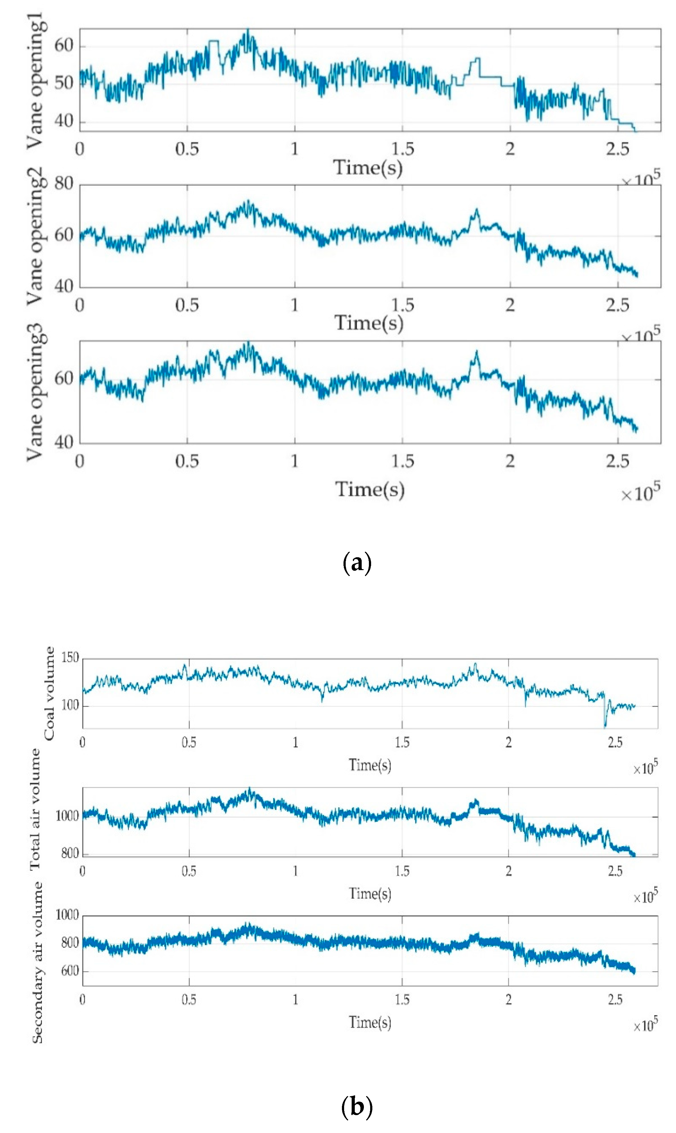
Figure 3. The corresponding field data is shown in Figure 4.
It follows from Figure 4a,b that the data of air volume and coal volume exhibits obvious volatility, whose noise needs to be reduced. In contrast, the AVOs of forced fan and induced fan have less fluctuation and noise.

2.2. Noise Reduction Based on SVD

The SVD problem of time-varying matrix can be expressed as the following formula, in general.
A ( t ) = U ( t ) ( t ) V T ( t )
Thereinto, A(t) is a m × n matrix; U(t) and V(t) are m × n and n × n unitary matrices; ( t ) is a m × n time-varying diagonal matrix. Simply speaking, the SVD of A(t) is a factorization of the form U ( t ) ( t ) V T ( t ) .
Considering the field data is in the real number field, we only discuss SVD in the real number field in this paper. Assume A ( t ) R m × n being a smoothly time-varying matrix, and consider the following equation system:
( t ) = U T ( t ) A ( t ) V ( t ) U ( t ) U T ( t ) = I m V ( t ) V T ( t ) = I n
where I m and I n are m × m and n × n matrices; orthogonal matrices V ( t ) R n × n and U ( t ) R m × m , and diagonal matrix ( t ) R m × n are the unknown matrices to be solved. Evidently, Equation (2) is equivalent to the time-varying SVD problem (1).
According to the filed data we get, A ( t ) can be composed of secondary air volume and coal volume. A ( t ) is a matrix of 250,000 × 2. Then, 95% of the sum of diagonal elements of ( t ) is chosen to form a new ( t ) . At last, a new matrix A ( t ) as the new secondary air volume and coal volume after noise reduction is recombined. A ( t ) is a factorization of the form U ( t ) ( t ) V T ( t ) . The corresponding sub-matrixes U ( t ) and V ( t ) are extracted from U ( t ) and V ( t ) , according to the length of the rows and columns of ( t ) 
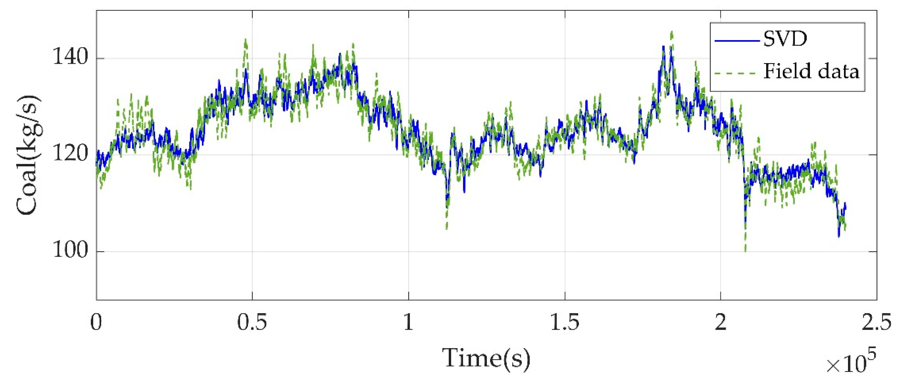
. Through SVD de-noising, the secondary air volume and coal are shown in Figure 5 and Figure 6.
As can be seen in Figure 5 and Figure 6, the noise in the total coal are obviously reduced. At the same time, the noise of secondary air volume is reduced by a certain amount. The obvious outliers have been removed.

2.3. BP Neural Network Screening Method

A BP neural network generally consists of an input layer, an output layer and a hidden layer connected by a group of weight factors. The basic architecture of BP neural network is shown in Figure 7.
According to the forward operation of input data, BP neural network calculates the final network error and transmits the error in the opposite direction. Based on the error, the weights can be adjusted under certain rules. After being trained with a large number of data samples, the neural network model can approach any nonlinear model.
Before training the neural network, normalization was necessary. Normalization can avoid some unnecessary numerical problems and unify evaluation standard. Normalization is also good for gradient descent algorithm, making the network converge quickly. The normalization used in this paper is shown in Equation (3a). The x is the input of the neural network. At the same time, the activation function of the neural network is the rectified linear unit shown in Equation (3b). The x is the output of the hidden layer.
The input layer of the model are the AVOs of the forced fan and the induced fan A, B, and the amount of coal. The output layer of the model is the total air volume.
x = x x min x max x min
f ( x ) = m a x ( 0 , x )
After normalization, the training samples and testing samples need to be prepared well. In this paper, 7800 groups of data from one day were labeled as accurate data and 80% of the data constitutes the training set. The rest constituted the validation set. A total of 250,000 groups of data another day constituted a testing set. The sampling time was 1 s.
Then the neural network is trained by training set. As a fully interconnected network, there are four neurons in the input layer, one neuron in the output layer, and 15 neurons in the hidden layer, respectively. The biases are random numbers.
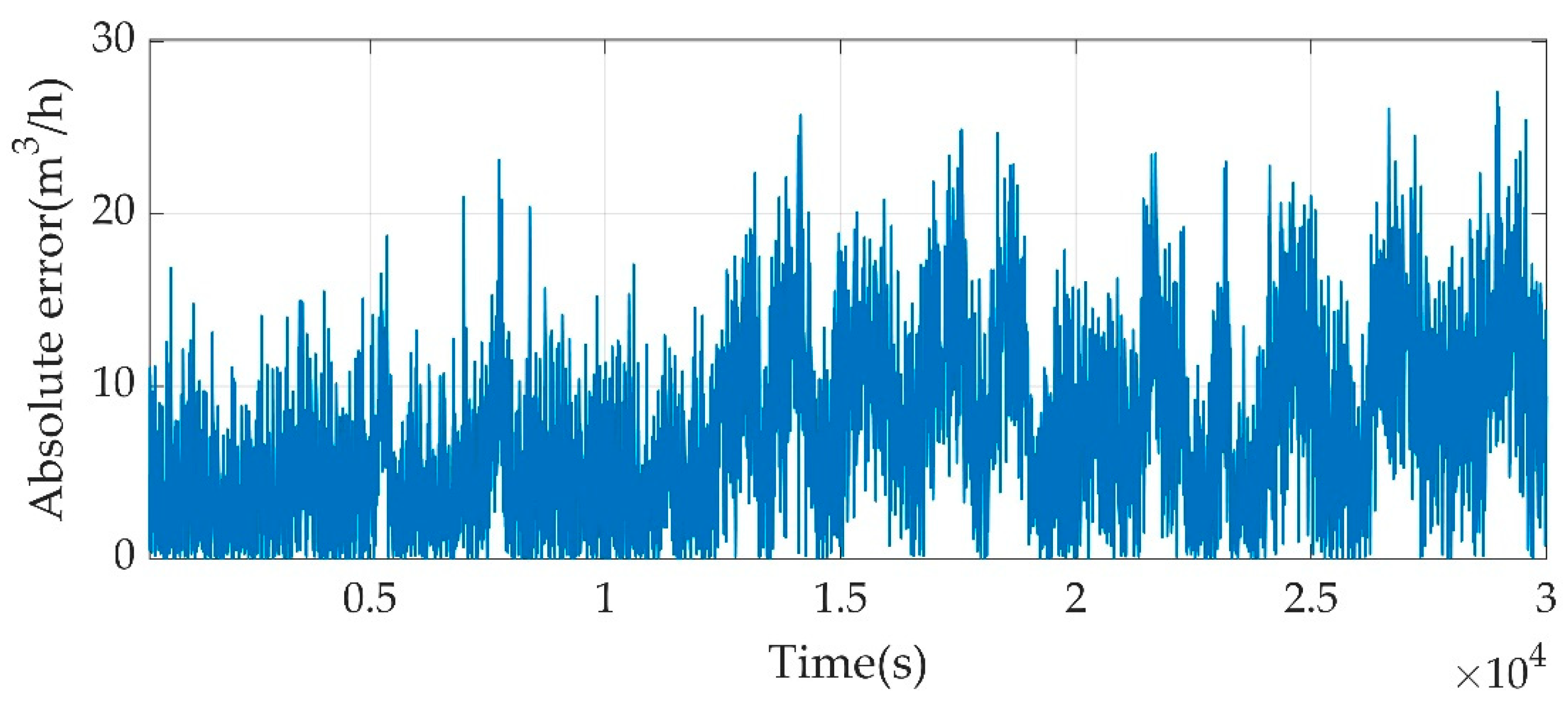
The trained model is validated by validation set and tested by testing set. The fit of the validation set reached 80%. The test results are shown in the following Figure 8 and Figure 9.
As can be seen, the absolute error between field data and calculated data is 20. We assumed that if the absolute error is within 5, the current value can be used for identification. At every 1000 points, we calculate the number of the identifiable data in the data length of 10,000. The data segment with the most identifiable data is the optimal identification data segment. A segment starting from 123,000 to 133,000 is the optimal segment.

3. Data-Driven Based Modeling and Simulation

Closed loop simulation is established based on actual power plant control strategy and dynamic model identified from the classified data segment. In order to design better controllers and reduce model complexity, PEM was used as the identification method. Then, historical field data is imported for verification.

3.1. Modeling by PEM

The prediction error method refers to a method of calculating the output from time (k + 1) to the future time using the input and output signals before time k. We need to adjust parameter θ to make the predicted root mean squared error reaching the minimum parameter estimation, after z(k) is given, the prediction error model is shown in Equation (4):
z ( k ) = f [ z ( k 1 ) , , z ( 1 ) , z ( 0 ) , u ( k 1 ) , , u ( 1 ) , u ( 0 ) , θ ] + e ( k , θ )
where z(k − 1) is the output of time k − 1; u(k − 1) is the input of time k − 1; e(k,θ) is the forecast error at time k; and θ is all parameters of the corresponding model.
In order to minimize the forecast error e(k,θ) and select a best model from Equation (4), some scalar functions JN(θ) related to the covariance matrix (5) of the prediction error were used as cost functions. Parametric estimation θ is called prediction error estimation when JN(θ) is minimized.
D N ( θ ) = 1 N n + 1 k = n N e ( k , θ ) e T ( k , θ )
where n is the beginning of the data; N is the end of the data.
The following two scalar functions (6) and (7) are usually used as the estimation criteria:
J 1 N ( θ ) = t r [ W D N ( θ ) ]
J 2 N ( θ ) = lg [ det D N ( θ ) ]
where W is a positive definite matrix.
Generally, J1N(θ) and J2N(θ) are nonlinear functions of the parameter θ, the prediction error parameter estimation method eventually becomes the optimal problem of J1N(θ) or J2N(θ). In the actual problem, if the covariance matrix of e(k,θ) is known, we choose J1N(θ) as the prediction error criterion. If the covariance matrix is unknown, we choose J2N(θ) as the prediction error criterion
The minimization of J1N(θ) or J2N(θ) can be obtained by making the nonlinear steady-state system model parameter estimation optimal such as gradient method and relaxation method.
According to the above principle, the linear autoregressive exogenous (ARX) model of the forced draft-controlled plant is established. It is transformed into the following transfer function for simulation.
y = 0.0564 z 0.9938 u 1 + 0.0042 z 0.9938 u 2 + 0.0095 z 0.9938 u 3 + 0.0061 z 0.9938 u 4
where y is the total air volume, u1 is AVO of forced draft fan, u2 is AVO of induced draft fan A, u3 is AVO of induced draft fan B, u4 is the total coal volume, and z is the z-transform operator.
The model identification image is as shown in Figure 10.
It is obvious that the identification model is similar to the actual plant. The volatility of identification model is consistent with the actual plant. Therefore, the proposed combined data-extraction method of SVD de-noising and BP classification is feasible.

3.2. Simulation Verification

After the model is established, closed loop simulation is also established. The control strategy of actual forced draft system is single PID control as shown in Figure 3. The parameters of PID are kp = 0.8, ki = 0.02, kd = 0 and the set-point of the total air volume is calculated by the boiler demand and the oxygen content of flue gas. The main steam flow is used as feed-forward to adjust the vane position of the forced draft fan. The simulation result is shown in Figure 11 and Figure 12
The simulation time is 50,000 s. It can be seen from Figure 11 and Figure 12 that the simulation of the total air volume is consistent with the fluctuation of the actual value. The simulation is near the set-point. The differences between the actual data and the simulation data exist due to the absences of the unknown disturbances and measurement noises in the simulation system, and it does not much affect the purpose of control design. In general, the data classification method and identification method are feasible. It is seen from Figure 12 that the actual control strategy does not track the set-point tightly and thus needs improvement for better control effect.

4. Data-Driven Based Control Design

The response of single PID controller to disturbance and delay is slow, and there will be obvious overshoot before stabilization. Thus the control strategies with ADRC and MPC, which have stronger anti-disturbance ability and better control performance based on predictive model respectively, are studied via the above simulation platform.

4.1. ADRC

ADRC was originally proposed for the general nth order process, where an nth order ADRC is used. However, accurate model order is usually unavailable in process control. Therefore, a low-order ADRC controller is usually preferred in practice [27]. The principle schematic of ADRC is shown in Figure 13:
Any 1st order disturbed system can be described as (9):
x ˙ 1 = f + b u y = x
where f is the total disturbance consisting of the unknown external disturbances and internal dynamics and b is a critical gain.
Then the system can be expanded into a 2nd order linear system (10):
x ˙ 1 = x 2 + b 0 u x ˙ 2 = f y = x 1
where b0 is an approximation of b.
Based on the expanded 2nd order system, a 2nd order expanded linear state observer (11) is designed as follows:
e 1 = y - z 1 z ˙ 1 = z 2 - β 1 e 1 + b 0 u z ˙ 2 = - β 2 e 1
It has been proven in [28] that z1, z2 will well track y, and f respectively, provided that the parameters β1, β2 are tuned reasonably.
The feedback is selected as follows (12) to compensate the expanded state:
u = u 0 z 2 b 0
The number of the tuning parameters has been reduced in [29] by combing the parameters as follows.
β 1 = 2 w 0 ,   β 2 = 2 w 0 2
where w0 correspond to the system bandwidth.
From the z-transfer function (8), it can be seen that when other inputs are analyzed as disturbances, including the AVO of induced draft fan and the total coal, the system can be considered as one 1st order linear plant with two disturbances. The ADRC is established based on the above principle. We set w0 = 0.2, b0 = 0.1. The parameters of the single PID controller are kp = 0.8, ki = 0.025, kd = 0. Figure 14 and Figure 15 show the comparator results among the simulation of ADRC, the simulation of PID control and field data.
It can be seen that, thanks to the compensation mechanism of ADRC, the simulation fluctuation of total air volume is greatly reduced and tightly closer to the set-point compared with single PID controller. Meanwhile, the AVO of forced draft fan is smaller than the actual data and the simulation of PID control. Therefore, the ADRC shows the better performance in the forced draft control.

4.2. Frequency-Domain Stability Analysis of ADRC

Frequency-domain stability analysis is very popular in analyzing the performance of ADRC [30,31,32], this paper analyzes the stability of ARDC based on the classical Bode plot. The control loop and the controlled object can be simplified to get the structure of the internal model control of the 2nd order extended state observer (ESO).
As seen from Figure 16, the model can be transformed into a standard structural form. The input signal u is the output of the controller, and the output signal y is the 1st order integral of the output of the controlled object. The transfer function of the internal model can be obtained as Equation (14).
ϕ ( s ) = b ( s + w 0 ) 2 b 0 ( s + a 1 ) ( s + w 0 ) 2 + [ b s - b 0 ( s + a 1 ) ] w 0 2
The characteristic equation of the closed-loop system can be written as Equation (15):
1 + ϕ ( s ) H ( s ) = 0
Considering the frequency response of φ(s)H(s), the effect of the bandwidth changes of the observer on the system performance is shown in Figure 17. The values of w0 are 0.05, 0.1, 0.3, 0.5, 0.8, and 1. The b0 is 0.1 and b is 0.05658, a1 is 0.0062. The corresponding cut-off frequencies and phase margins are shown in Table 1.
It is obvious that w0 is able to impact the response speed and stability of the system. The larger w0 is, the higher the cut-off frequency is, and the faster the response speed of the system is. However the absolute value of phase margin of the system is reduced, which reduces the stability of the system. Therefore, the estimation accuracy of ESO is related to w0 [33]. The increase of w0 makes the accuracy of ESO estimation higher, but the system sensitive to noise. Therefore, w0 needs to be limited to a suitable range, which can not only play a role in disturbance rejection, but also ensure a certain observation accuracy.

4.3. MPC

In addition to ADRC, MPC is also widely perceived to give favorable disturbance rejection performance [34,35]. MPC is proposed for linear or quasi-linear system control in the early days and has been widely used in the process industry. The basic control structure of MPC is shown in Figure 18. The MPC includes prediction model, feedback correction and receding-horizon optimization. The prediction model is used to predict the future output of the system. Optimal control problem with multi-variable processes, constraints and large inertia can be solved by MPC.
In Figure 18, y(k) is the actual output of the system, u(k) is the input of the system and r(k) is set-point of output of the system.
According the transfer functions (9), the discrete-time state-space expressions of the prediction model is established as Equation (16). The AVO of forced draft fan is taken as the input, and the total air volume is taken as the output.
x ( k + 1 ) = G x ( k ) + H u ( k ) y = C x ( k ) + D u ( k )
where, the parameters are set as G = 0.9938, H = 0.25, C = −0.2244, D = 0.
The optimization function is designed as Equation (17) and considering the AVO as the constraints shown as Equation (18):
J = ( Y r - Y k ) * Q * ( Y r Y k ) + Δ U * R * Δ U
0 u 100 5 Δ u 5
where Yr is the set-point of output; Yk is the field output; Q is the error weight; R is the control weight; ΔU is the input increment.
The prediction horizon is taken as 80 s, and the control horizon 5 s. The objective function is transformed into the standard quadratic form and the optimization problem is solved by combining the constraints.

4.4. Simulation Result

The results of the simulation are shown in Figure 19 and Figure 20.
As can be seen from Figure 19 and Figure 20, the simulation of the total air volume can almost completely fit the set-point, especially when the set-point fluctuates greatly. At the beginning of simulation, compared with ADRC and single PID controller, the total air volume under MPC control has no obvious mutation. However, compared with ADRC and single PID, the AVO fluctuates greatly, which cannot meet the actual demand. The great fluctuation may cause various problems for the AVO.
In general, the response of single PID control to disturbance is slow, and it is difficult to overcome a large number of disturbances. In contrast to single PID control, MPC can mitigate the disturbance well and make the output reach the set-point. However, it is too sensitive to disturbances so that the AVO fluctuation is too large. Among the three kinds of control strategy, ADRC can balance the accuracy of output and the fluctuation of AVO. The ability of anti-disturbance of ADRC is remarkable.

5. Conclusions

The ever-growing stringent regulations on energy saving and emission reduction makes it a tremendous yet straightaway necessity to precisely model and efficiently control the forced draft control of boiler combustion systems. To tackle the problem of more noises and disturbances in the forced draft control system, this paper proposes an SVD-BP hybrid approach to classify the field data. Then, ADRC and MPC are used, respectively, for disturbance rejection for better forced draft control effect. Several conclusions are drawn from the simulation results. (i) SVD-BP can effectively reduce the noise, and successfully classify the data of the forced draft control system. The simulation results prove that the classified data for modeling is sufficient to develop an accurate model. The fit of the model has been successfully improved from 44% to 65%. (ii) ADRC can improve the disturbance rejection effect within the reasonable range of AVO, comparing with single MPC and PID to achieve the purpose of controlling boiler combustion better. According to total air volume control responses, the proposed method is able to increase the performance by about 8%. In summary, the proposed SVD-BP can be applied in boiler forced draft systems to classify the field data, and ADRC can improve the disturbance rejection performance.

Author Contributions

Q.W. proposed the SVD-BP data extraction method and ADRC control for the forced draft system. H.X. and L.S. established the simulation model of the forced draft system, and L.P. is the mentor of the whole process. All authors have read and agreed to the published version of the manuscript.

Acknowledgments

This work was supported by the National Natural Science Foundation of China under Grants 51936003 and 51576040. The authors would like to give our sincere appreciation to the editor and anonymous referees for their careful review and valuable suggestions.

Conflicts of Interest

The authors declare no conflict of interest.

Abbreviations

SVDSingular value decomposition
PEMPrediction error method
BPBack propagation
ADRCActive disturbance rejection control
PIDProportional-integral-differential
MPCModel predictive control
AVOAdjustable vane opening
ARXAutoregressive exogenous
ESOExtended state observer
u1AVO of forced draft fan
u2AVO of induced draft fan A
u3AVO of induced draft fan B
u4The total coal volume
yThe total air volume
zThe z-transform operator

References

  1. Rahat, A.A.; Wang, C.; Everson, R.M.; Fieldsend, J.E. Everson Data-driven multi-objective optimisation of coal-fired boiler combustion systems. Appl. Energy 2018, 229, 446–458. [Google Scholar] [CrossRef] [Green Version]
  2. Ren, F.; Li, Z.; Liu, G.; Chen, Z.; Zhu, Q. Combustion and NOx emissions characteristics of a down-fired 660-MWeutility boiler retro-fitted with air-surrounding-fuel concept. Energy 2011, 36, 70–77. [Google Scholar] [CrossRef]
  3. Lawn, C.J. Principles of Combustion Engineering for Boilers; Academic Press: Orlando, FL, USA, 1987. [Google Scholar]
  4. Gu, Y.; Zhao, W.; Wu, Z. Online adaptive least squares support vector machine and its application in utility boiler combustion optimization systems. J. Process Control 2011, 21, 1040–1048. [Google Scholar] [CrossRef]
  5. Liu, X.; Bansal, R.C. Integrating multi-objective optimization with computational fluid dynamics to optimize boiler combustion process of a coal fired power plant. Appl. Energy 2014, 130, 658–669. [Google Scholar] [CrossRef]
  6. Zhu, J.; Ge, Z.; Song, Z.; Gao, F. Review and big data perspectives on robust data mining approaches for industrial process modeling with outliers and missing data. Annu. Rev. Control 2018, 46, 107–133. [Google Scholar] [CrossRef]
  7. Chen, Y.; Liang, X.; Zuo, M.J. An improved singular value decomposition-based method for gear tooth crack detection and severity assessment. J. Sound Vib. 2020, 468, 115068. [Google Scholar] [CrossRef]
  8. Wang, P.; Zhou, W.; Li, H. A singular value decomposition-based guided wave array signal processing approach for weak signals with low signal-to-noise ratios. Mech. Syst. Signal. Process. 2019, 141, 106450. [Google Scholar] [CrossRef]
  9. Huang, Y.; Huang, C.; Ding, J.; Liu, Z. Fault diagnosis on railway vehicle bearing based on fast extended singular value decomposition packet. Measurement 2019, 107277. [Google Scholar] [CrossRef]
  10. Chen, J.; Zhang, Y. Online singular value decomposition of time-varying matrix via zeroing neural dynamics. Neurocomputing 2019. [Google Scholar] [CrossRef]
  11. Zhou, S.; Liu, N.; Shen, C.; Zhang, L.; He, T.; Yu, B.; Li, J. An adaptive Kalman filtering algorithm based on back-propagation (BP) neural network applied for simultaneously detection of exhaled CO and N2O. Spectrochim. Acta A 2019, 223, 117332. [Google Scholar] [CrossRef]
  12. Wu, Y.; Gao, R.; Yang, J. Prediction of coal and gas outburst a method based on the BP neural network optimized by GASA. Process Saf. Environ. Prot. 2020, 133, 64–72. [Google Scholar] [CrossRef]
  13. Li, X.; Cheng, X.; Wu, W.; Wang, Q.; Tong, Z.; Zhang, X.; Li, Y. Forecasting of bioaerosol concentration by a Back Propagation neural network model. Sci. Total Environ. 2020, 698. [Google Scholar] [CrossRef]
  14. Yong-song, L.; Jian-min, Y.; Jian-ping, C.; Jing, X. Analysis of 3D In-situ Stress Field and Query System’s Development Based on Visual BP Neural Network. Procedia Earth Planet. Sci. 2012, 5, 64–69. [Google Scholar] [CrossRef] [Green Version]
  15. Maruta, I.; Sugie, T. Stabilized Prediction Error Method for Closed-loop Identification of Unstable Systems. IFAC PapersOnLine 2018, 51, 479–484. [Google Scholar] [CrossRef]
  16. Parchami, M.; Amindavar, H.; Zhu, W.P. Speech reverberation suppression for time-varying environments using weighted prediction error method with time-varying autoregressive model. Speech Commun. 2019, 109, 1–14. [Google Scholar] [CrossRef]
  17. Brunot, M.; Janot, A.; Carrillo, F.; Gautier, M. A separable prediction error method for robot identification. IFAC PapersOnLine 2016, 49, 487–492. [Google Scholar] [CrossRef]
  18. Flaus, J.M.; Cheruy, A. Estimation of the State and Parameters of a Bioprocess Using the Recursive Prediction Error Method. IFAC Proc. Vol. 1989, 22, 6. [Google Scholar] [CrossRef]
  19. Sun, L.; Shen, J.; Hua, Q.; Lee, K.Y. Data-driven oxygen excess ratio control for proton exchange membrane fuel cell. Appl. Energy 2018, 231, 866–875. [Google Scholar] [CrossRef]
  20. Sun, L.; Jin, Y.; You, F. Active disturbance rejection temperature control of open-cathode proton exchange membrane fuel cell. Appl. Energy 2020, 261, 114381. [Google Scholar] [CrossRef]
  21. Sun, L.; Zhang, Y.; Li, D.; Lee, K.Y. Tuning of Active Disturbance Rejection Control with application to power plant furnace regulation. Control Eng. Pract. 2019, 92, 104122. [Google Scholar] [CrossRef]
  22. Chen, S.; Xue, W.; Huang, Y. On active disturbance rejection control for nonlinear systems with multiple uncertainties and nonlinear measurement. Int. J. Robust Nonlinear Control 2020. [Google Scholar] [CrossRef]
  23. Peng, H.; Li, F.; Kan, Z. A novel distributed model predictive control method based on a substructuring technique for smart tensegrity structure vibrations. J. Sound Vib. 2020, 471, 115171. [Google Scholar] [CrossRef]
  24. Shang, C.; You, F. A data-driven robust optimization approach to scenario-based stochastic model predictive control. J. Process Control 2019, 75, 24–39. [Google Scholar] [CrossRef] [Green Version]
  25. Hou, J.; Song, Z.; Hofmann, H.; Sun, J. Adaptive model predictive control for hybrid energy storage energy management in all-electric ship microgrids. Energy Convers. Manag. 2019, 198, 111929. [Google Scholar] [CrossRef]
  26. He, H.; Quan, S.; Wang, Y.X. Hydrogen circulation system model predictive control for polymer electrolyte membrane fuel cell-based electric vehicle application. Int. J. Hydrog. Energy 2020. [Google Scholar] [CrossRef]
  27. Sun, L.; Li, D.; Hu, K.; Lee, K.Y.; Pan, F. On tuning and practical implementation of active disturbance rejection controller: A case study from a regenerative heater in a 1000 MW power plant. Ind. Eng. Chem. Res. 2016, 55, 6686–6695. [Google Scholar] [CrossRef]
  28. Aström, K.J.; Hägglund, T. Advanced PID Control; ISA Press: Research Triangle Park, NC, USA, 2006; 461p. [Google Scholar]
  29. Sun, L.; Li, G.; Hua, Q.S.; Jin, Y. A hybrid paradigm combining model-based and data-driven methods for fuel cell stack cooling control. Renew. Energy 2020, 147, 1642–1652. [Google Scholar] [CrossRef]
  30. Chen, S.; Xue, W.; Zhong, S.; Huang, Y. On comparison of modified ADRCs for nonlinear uncertain systems with time delay. Sci. China Inf. Sci. 2018, 61, 70223. [Google Scholar] [CrossRef] [Green Version]
  31. Geng, X.; Liu, T.; Hao, S.; Zhong, C.; Wang, Q.-G. Anti-windup design of active disturbance rejection control for sampled systems with input delay. Int. J. Robust Nonlinear Control 2019. [Google Scholar] [CrossRef]
  32. Nie, Z.Y.; Zhu, C.; Wang, Q.G.; Gao, Z.; Shao, H.; Luo, J.-L. Design, analysis and application of a new disturbance rejection PID for uncertain systems. ISA Trans. 2020. [Google Scholar] [CrossRef]
  33. Stanković, M.R.; Madonski, R.; Shao, S.; Mikluc, D. On dealing with harmonic uncertainties in the class of active disturbance rejection controllers. Int. J. Control 2020. [Google Scholar] [CrossRef]
  34. Kong, X.; Liu, X.; Ma, L.; Lee, K.Y. Hierarchical distributed model predictive control of standalone wind/solar/battery power system. IEEE Trans. Syst. Man Cybern. Syst. 2019, 49, 1570–1581. [Google Scholar] [CrossRef]
  35. Hou, J.; Song, Z.; Park, H.; Hofmann, H.; Sun, J. Implementation and evaluation of real-time model predictive control for load fluctuations mitigation in all-electric ship propulsion systems. Appl. Energy 2018, 230, 62–77. [Google Scholar] [CrossRef]
Figure 1. Boiler combustion system.
Sustainability 12 04171 g001
Figure 2. Forced draft system.
Sustainability 12 04171 g002
Figure 3. Forced draft control system.
Sustainability 12 04171 g003
Figure 4. Field data. (a) Vane opening1: Adjustable vane opening (AVO) of forced fan (%); Vane opening2: AVO of induced fan A (%); Vane opening3: AVO of induced fan B (%). (b) Coal volume (kg/s); total air volume (m3/h); secondary air volume (m3/h).
Sustainability 12 04171 g004
Figure 5. The total coal amount.
Sustainability 12 04171 g005
Figure 6. The secondary air volume.
Sustainability 12 04171 g006
Figure 7. The basic architecture of back propagation (BP) neural network.
Sustainability 12 04171 g007
Figure 8. The test results of BP neural network.
Sustainability 12 04171 g008
Figure 9. Absolute error between field data and calculated data.
Sustainability 12 04171 g009
Figure 10. Air volume increment of identification model and actual plant.
Sustainability 12 04171 g010
Figure 11. The AVO of the forced draft fan.
Sustainability 12 04171 g011
Figure 12. The total air volume.
Sustainability 12 04171 g012
Figure 13. Principle schematic of active disturbance rejection control (ADRC). r is the set point; y is the output; kp and b0 are the parameters of controller. Gp denotes the controlled object. z2 is the total disturbance.
Sustainability 12 04171 g013
Figure 14. The AVO of the forced draft fan.
Sustainability 12 04171 g014
Figure 15. The total air volume.
Sustainability 12 04171 g015
Figure 16. The internal model control.
Sustainability 12 04171 g016
Figure 17. Bode diagram of the system.
Sustainability 12 04171 g017
Figure 18. The basic control structure of model predictive control (MPC).
Sustainability 12 04171 g018
Figure 19. The AVO of the forced draft fan.
Sustainability 12 04171 g019
Figure 20. The total air volume.
Sustainability 12 04171 g020
Table 1. Phase margin and cut-off frequency of the system.
w0Cut-Off Frequency (rad/s)Phase Margin (/°)
0.050.375687.5564
0.10.406187.1007
0.30.427880.2411
0.50.449873.8828
0.80.497469.7333
10.526868.7269

