Article

Near Trapping Effect on Wave-Power Extraction by Linear Periodic Arrays

1
State Key Laboratory of Coastal and Offshore Engineering, Dalian University of Technology, Dalian 116024, China
2
Department of Engineering Science, Uppsala University, 75239 Uppsala, Sweden
*
Author to whom correspondence should be addressed.
Sustainability 2020, 12(1), 29; https://doi.org/10.3390/su12010029
Submission received: 22 October 2019 / Revised: 12 December 2019 / Accepted: 16 December 2019 / Published: 18 December 2019

Abstract

:
Near trapping is a kind of strong hydrodynamic interaction phenomenon in a regular array under specific incident wave conditions, which causes the excitation force on the structures in the array to change suddenly. In this paper, based on linear potential flow theory, the effects of near trapping on the hydrodynamic interaction and wave-power extraction characteristics of linear periodic arrays composed of the oscillating float type wave energy converters are studied by using the higher-order boundary element method in a frequency domain. The parameters considered include the separation spacing, number of devices, and incident wave direction. It is found that the near trapping significantly reduces the overall wave-power extraction, especially for the cases with a large number of devices, and changes the trend of the power distribution. The occurrence of the near trapping phenomenon depends on the ratio of the separation spacing to the wavelength and the incident wave direction. The results highlight the effective layout of linear arrays under the influence of near trapping, which not only ensures the total production power, but also reduces the power difference among wave energy converters.

1. Introduction

The arrays of wave energy converters (WECs) are a necessary trend of wave energy utilization for commercial viability. However, the hydrodynamic interactions among floating bodies in an array have a great effect on the overall wave-power extraction. Therefore, the research on parameters affecting the hydrodynamic interaction between waves and bodies is popular for many scholars, including the number of units, separation spacing, incident wave condition, geometry, and layout. Zhong and Yeung [1] investigated the effects of the spacing and layout on the power extraction. Göteman [2] studied the effect of geometries and configurations on the array performance. Mcguinness and Thomas [3] considered the hydrodynamic optimization of the linear and circular arrays, and concluded that the incident wave direction has a great influence on the overall performance. Both Andres et al. [4] and Göteman et al. [5] analyzed the effect of number of WECs and the spacing between WECs under the various wave conditions. Stratigaki et al. [6] set up the experiment array composed of up to 25 identical WECs, and studied the important influence of array effect on the power absorption and the wave field by considering the quantity, spacing, and incident wave conditions.
As early as the end of 20th century, an important phenomenon, near trapping, attracted extensive attention when the hydrodynamic interactions of a column array were investigated. When the near trapping phenomenon occurs, rather large free wave surface oscillations can be observed near the columns and the wave force on the columns is amplified. Before the investigation of near trapping, Evans and Linton [7,8] carried out numerical studies on the wave surface distribution around the vertical-cylinder structures in a wave flume, and observed the trapping phenomenon and different forms of trapping modes around the structure. Maniar and Newman [9] studied the wave diffraction by a long array of bottom-mounted cylinders arranged at equal spacing in open water. The results showed that the interaction among cylinders has a significant effect on the force and wave surface distribution. When the number of cylinders in the array is large, the force on the middle cylinder can be ten times that on the single cylinder in open water at some incident frequencies, while a large number of waves are stranded near the cylinders and fewer waves propagate to the far field. This phenomenon is very close to the trapping phenomenon observed in the flume. Motivated by the work of Maniar and Newman [9], Evans and Porter [10] analyzed the peak forces on the circular arrays and defined near trapping as ‘a local oscillation in the vicinity of the array at a well-defined frequency which decays slowly as its energy leaks away due to wave radiation at large distances’. Walker and Eatock Taylor [11] stated that no exact trapping phenomenon occurs for a finite array in open water, and the corresponding phenomenon is described as near trapping. Siddorn and Eatock Taylor [12] studied the hydrodynamic characteristics for the square array of floating truncated cylinders, and proved that near trapping would be excited under the appropriate incident wave conditions. Wolgamot et al. [13] considered the connection between near trapping and radiation in arrays of oscillating truncated cylinders without the incident waves.
As a common hydrodynamic interaction phenomenon in regular arrays, many research results on the near trapping phenomenon have been published, but they have rarely been used to guide the wave-power extraction of wave energy arrays. In this paper, the near trapping phenomenon and its effects on the excitation force and energy absorption characteristics of linear periodic arrays are discussed. The wave-body interactions problem is calculated by a higher-order boundary element method based on linear potential flow theory in a frequency-domain. The parameters considered include the spacing among absorbers, number of absorbers, and incident wave direction. The main objective of the present study is to investigate the performance of the array under the effects of near trapping with different layout parameters. The basic theory of hydrodynamic and extraction principles of wave power are briefly introduced in Section 2, the results and discussion are presented in Section 3, and the conclusion is summarized in Section 4.

2. Methods and Verification

The coordinate system of the array composed of the cylindrical WECs is shown in Figure 1. The coordinate system OXYZ is the global coordinate system and the coordinate systems o1x1y1z1, o2x2y2z2, and onxnynzn are local coordinate systems of the 1st, 2nd and n-th absorber, respectively. The origin and xy plane of all coordinate systems are on the mean free water surface and z is the vertical coordinate (positive upwards). In Figure 1, Sf is the free water surface; Sb is body surface, Sb = Sb,1 + Sb,2 + … + Sb,n; Sd is the seabed, and S is the infinity.

2.1. Hydrodynamics of Wave-Body Interaction

In this paper, based on linear potential flow theory, the spatial velocity potential φ (x, y, z) satisfies the Laplace equation in the whole flow field, where x, y, and z are the global spatial coordinates. All absorbers oscillate in one degree of freedom (e.g., heave mode), so the total velocity potential φ for N absorbers can be decomposed by,
ϕ = ϕ I + ϕ D + j = 1 N u j ϕ j R
where φI is the incident potential, φD the diffraction potential, φjR the radiation potential due to the motion of the j-th absorber with unit velocity amplitude and the other absorbers remaining stationary, and uj is the oscillating velocity of j-th absorber.
The velocity potential for an incident wave with the wave amplitude A0 can be written as follows,
ϕ I = i g A 0 ω cosh k ( z + h ) cosh k h e i k x
where ω is the angular frequency of the incident wave, which satisfies the dispersion relation, that is, ω2 = gk tanh(kh), g is the gravity acceleration, k is the wave number, and h is the water depth.
The diffraction and radiation potential meet the free water surface, body surface, and infinite Sommerfeld boundary conditions, respectively, as the formula (3),
{ ( z ω 2 g ) [ ϕ D , ϕ R ] = 0   ( o n   S f )   ϕ D n = ϕ I n   ( o n   S b )   ϕ j R n = n j = n ( j )   ( o n   S b , j )   ϕ j R n = n j = 0   ( o n   S b , i j ) z [ ϕ D , ϕ R ] = 0   ( o n   S d ) lim r r ( r i k ) [ ϕ D , ϕ R ] = 0   ( o n   S ) ( j = 1 , 2 , N )
where nj is the generalized normal vector and n(j) represents the normal vector of the j-th absorber.
The boundary integral Equation (4) was established by using Green’s function G(x, x0) [14] which satisfies the free water surface condition to solve the velocity potential. The integral region can be confined to the surface of absorbers, thus reducing the requirement of computer memory and improving the computational efficiency,
α ϕ ( x 0 ) S b G ( x , x 0 ) n ϕ ( x ) d S = S b ϕ ( x , x 0 ) n G ( x ) d S
where x and x0 are the field and source points, respectively. The solid angle coefficient α related to the body surface is calculated directly. The integral Equation (4) is resolved by the higher order boundary element method [15] with a discretization of the body surface into elements. After the velocity potential is obtained, the excitation force FjE on the j-th absorber is obtained by integrating the dynamic pressure on the wetted surface due to the incident and diffraction potentials, as shown in formula (5). The radiation force FjR, added mass μji and radiation damping λji on the j-th absorber subject to a unit forced motion of the i-th absorber can be written as formula (6) and (7), where ρ is the seawater density.
F j E = i ω ρ S b , j ( ϕ I + ϕ D ) n j d S
F j R = i ω ρ i = 1 N u i S b , j ϕ i R n j d S = i ω ρ ( u j S b , j ϕ j R n j d S + j i N u i S b , j ϕ i R n j d S )
μ j j = Re ( ρ S b , j ϕ j R n j d S ) ,   μ j i = Re ( ρ S b , j ϕ i R n j d S ) ,   μ i j = μ j i λ j j = 1 ω Re ( ρ S b , j ϕ j R n j d S ) ,   λ j i = 1 ω Re ( ρ S b , j ϕ i R n j d S ) ,   λ i j = λ j i
The power take-off (PTO) system is composed of a spring and a damper, exerting the spring and damping reaction force on the absorber. The damping force is assumed to be linear with respect to the velocity of the absorber. The reaction force of PTO can be expressed as formula (8), where the mechanical damping and the spring stiffness of the j-th PTO are Rj and KPTO, j, respectively.
F P T O , j = ( 1 i ω K P T O , j R j ) u j
According to Newton’s second law, the motion equation in the frequency domain for an array of N absorbers oscillating in the single degree of freedom is given by,
{ i ω ( [ M 1 0 M j 0 M N ] + [ μ 11 μ 1 N μ i j μ N 1 μ N N ] ) + ( [ λ 11 λ 1 N λ i j λ N 1 λ N N ] + [ R 1 0 R j 0 R N ] ) 1 i ω [ K 1 0 K j 0 K N ] } ( u 1 u j u N ) = ( F 1 E F j E F N E )
where Mj and Kj represent the mass and the restoring stiffness coefficient of the j-th absorber, respectively. Kj = Cj + KPTO,j includes the hydrodynamic restoring coefficient Cj and the spring stiffness of the PTO KPTO, j.

2.2. Extraction Principles of Wave Power

The power extracted by an array of N identical WECs is obtained as the product of the mechanical damping and the velocity squared,
P array ( ω , β ) = j = 1 N P j ( ω , β ) = j = 1 N 1 2 R j u j u j * = 1 2 { U } T [ R ] { U }
where Parray is the total power absorbed by an array, Pj is the power of each WEC in the array, β is the direction of incident wave, and superscript T and superscript * represent the transpose and conjugate of the matrix, respectively. In addition, [R] is the diagonal matrix about the mechanical damping systems, and the velocity vector of the absorbers {U} is N dimensional column vector, which can be obtained by formula (11),
{ U } = { F } ( [ R ] + [ B ] ) + i ω ( [ M ] + [ A ] [ K ] / ω 2 )
where {F} is the column vector of the excitation forces, [M] and [K] the diagonal mass matrix and restoring force coefficient matrix, and [A] and [B] the added mass and radiation damping matrix, respectively. The diagonal matrices [R], [M] and [K] consist of one diagonal element per absorber, and the vectors {U} and {F} are composed of one element per absorber. The non-diagonal elements of the dense matrices ([A] and [B]) are taken as the result of the hydrodynamic interaction effects among the array.
The concept of the interaction factor is widely used to explain the interaction effects between absorbers in the WEC array. For the large WEC arrays, the high total power and uniform power distribution are considered as two objectives of effective arrays. So the mean interaction factor Qmean and single interaction factor Qsingle,j are used to illustrate the performance of the WEC array. The interaction factor is defined as follows,
Q mean ( ω , β ) = P array N P isolated = 1 N j = 1 N Q sin gle , j ( ω , β )
where, Pisolated is the optimal power absorbed by the single isolated WEC in open water, and the damping of each PTO is selected to be the optimal damping [16], as formula (13) shows,
R opt , iso = λ 2 + [ ω ( M + μ ) K / ω ] 2
where M, K, μ and λ are the mass and the restoring force coefficient, and the added mass and radiation damping of the single isolated absorber in open water.
In the case of Qmean > 1, the interaction effects between the array is favorable, and the mean power absorbed by the whole array is greater than the optimal power of the single isolated WEC. For Qsingle,j > 1, this means that the power absorbed by the j-th WEC in the array is greater than that of the single isolated WEC. It is considered that the WEC array is very constructive and efficient if Qmean ≥ 1 and all Qsingle,j ≥ 1.

2.3. Numerical Verification

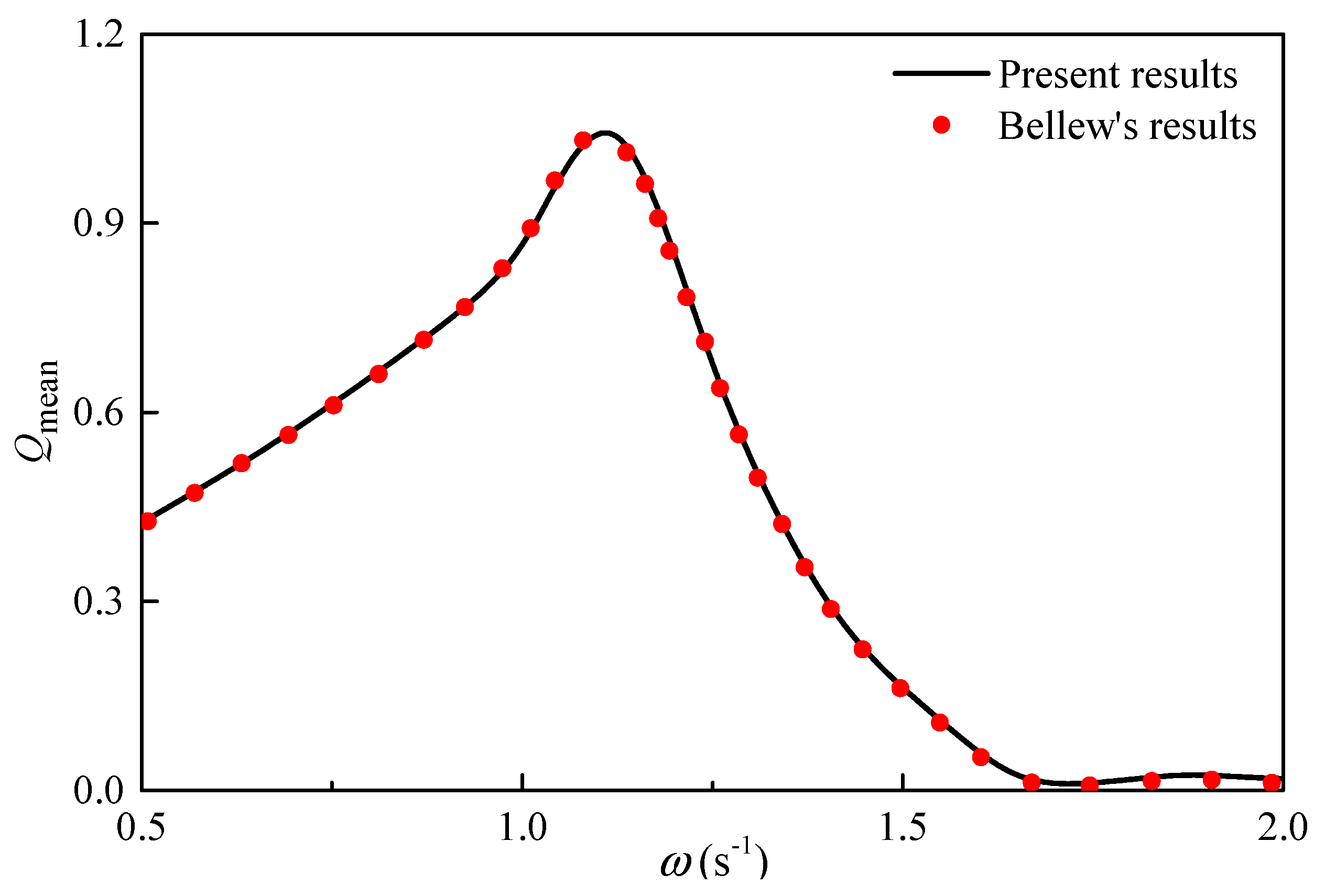
To verify the numerical model, the predicted mean interaction factor of a WEC array is compared with the published results [17] from WAMIT, a computer program based on the linear and second-order potential theory for analyzing floating or submerged bodies, in the presence of ocean waves. The array consists of five heaving hemispherical absorbers with a linear equidistant arrangement. The main parameters are the radius of per hemisphere a = 5 m, the spacing between adjacent absorbers 4a, and the water depth 7a, as shown in Figure 2.
The comparison of mean interaction factor between the present and published results in beam seas is shown in Figure 3. The PTO damping matrix in the total power calculation is defined according to the optimal damping given in formula (13), where the coefficient of the single isolated structure is replaced with the coefficient matrix of the array, and the main diagonal elements of the damping matrix are corresponding to each structure in the array. It can be seen that two results are in good agreement with each other, which supports the proposed numerical model.

3. Results and Discussion

In this section, the equidistant linear array composed of several WECs is studied. Each cylinder in the array is identical and considered as a truncated cylinder oscillating in surge or heave mode. The effects of near trapping on excitation forces and wave-power extraction are investigated. The parameters of spacing between the adjacent WECs, number of the WECs and incident wave directions are considered.
The arrangement of the number of the WECs N = 9 is shown in Figure 4. The radius and draught of the cylinder are a = 1.0 m and a/2. If not specified, the spacing between the adjacent WECs is D = 2d = 8a. The effect of water depth is not taken into account here and the considered water depth is h = 20 m. In the numerical calculation, each cylinder is divided into 200 panels.
To study the influence of the near trapping phenomenon on the WEC array, the performance of the surging array and heaving array are investigated, respectively. The schematic representation of the heaving and surging WECs are shown in Figure 5a,b, respectively. Unlike Babarit’s model design [18], which considers the same body surface facing with the incident waves, the same cylinder is considered as the wave-power absorber of the surging and heaving WEC, and the natural frequencies in surge and heave modes are made consistent by adjusting the spring stiffness of the PTO. Thus, the spring stiffness KPTO,j of the j-th heaving absorber is defined as 0 and the j-th surging absorber is equal to 25.5 kN/m. The PTO damping is taken as the optimal damping of the single isolated absorber. According to formula (13), the PTO damping of both heaving and surging WECs is equal to 1.76 kN/m.

3.1. Excitation Forces

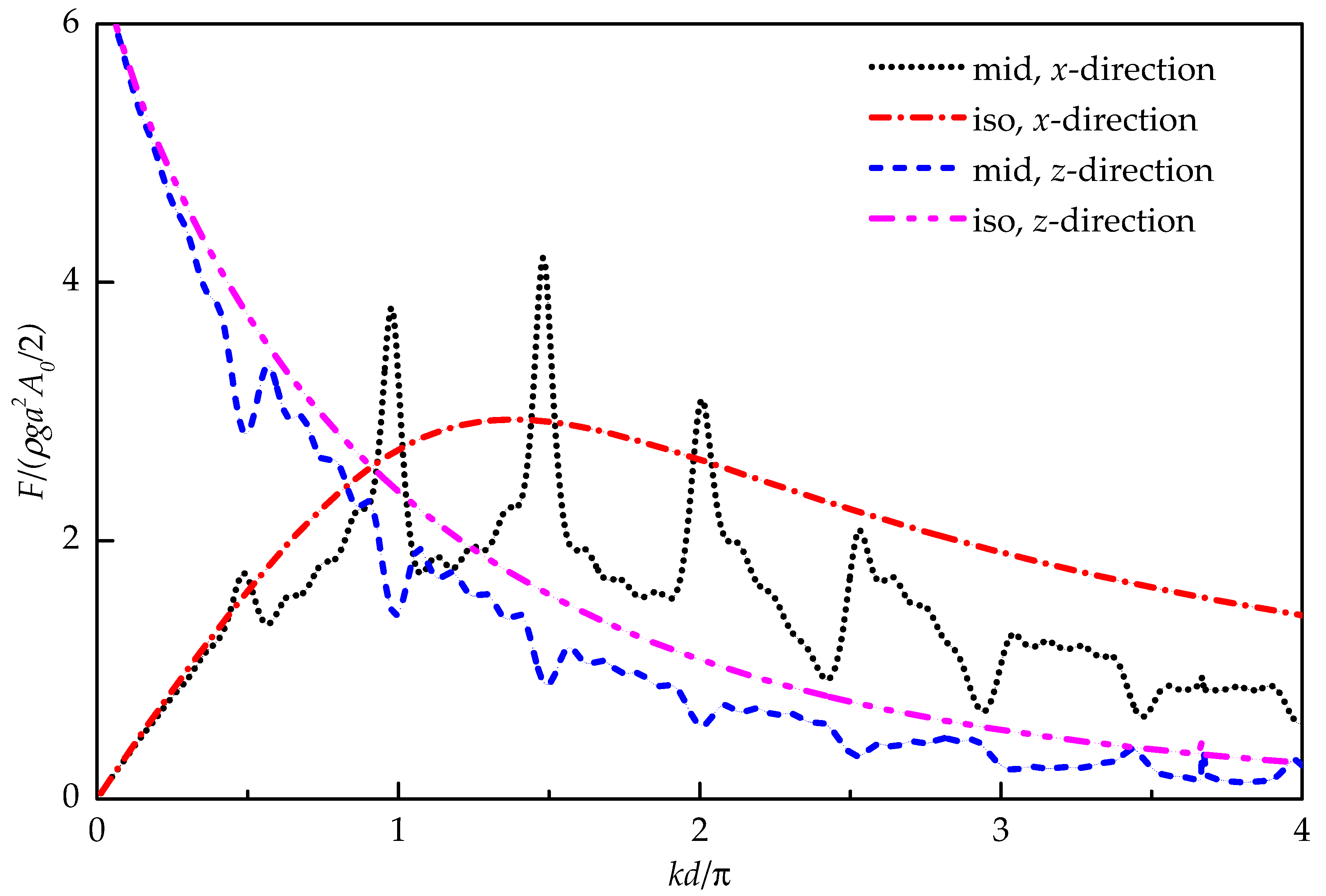
In this section, the magnitude of the wave excitation forces in x-direction and z-direction of the 5th cylinder in the middle of the array is studied and compared with that of the single cylinder in open water, for head seas (i.e., β = 0°), over a range of frequencies (i.e., 0 < kd < 4π), as shown in Figure 6. Here the excitation force is normalized by the incident wave amplitude, water density, gravity acceleration, radius, and draught.
From Figure 6, it can be found that there are a series of sudden changes in the excitation force on the middle cylinder at kd/π ≈ 0.5n (n = 1, 2, …). In particular, the excitation force in the x-direction has a large narrow peak when n is small. By comparing the excitation force curves in the x-direction with those in the z-direction, it can be found that the sudden changes between them are just the opposite, i.e., if there is a sudden crest in the x-direction, a sudden trough occurs in the z-direction at the same frequency. These sudden changes are due to the occurrence of near trapping. A close connection between a series of peaks of the horizontal excitation force and the near trapping has been proved by Maniar and Newman [9]. The first and second peaks (i.e., kd/π = 0.5 and 1.0) correspond to Neumann and Dirichlet trapped waves, respectively, and the subsequent peaks are associated with ‘nearly-trapped waves’. Neumann and Dirichlet trapped modes satisfy Neumann condition (i.e., ∂φ/∂n = 0) and Dirichlet condition (i.e., φ = 0) on all central planes among cylinders, respectively. Once Neumann condition is satisfied, the motions of two adjacent absorbers are opposite, and the phase difference between them is ±π. However, the phase in Dirichlet trapped modes is practically identical along the array. Except for these critical wave numbers in the near trapping phenomenon, the most common hydrodynamic phenomena in an array can be observed in comparison with the excitation force on the single isolated absorber. That is, for the long wave, the excitation force on the middle absorber is basically equal with that on the single isolated one because the absorber is small enough relative to the wavelength and the wave diffraction is strong. For the short wave, the excitation force on the middle absorber is lower than that on the single isolated one due to the sheltering and reflection of the upstream absorbers.
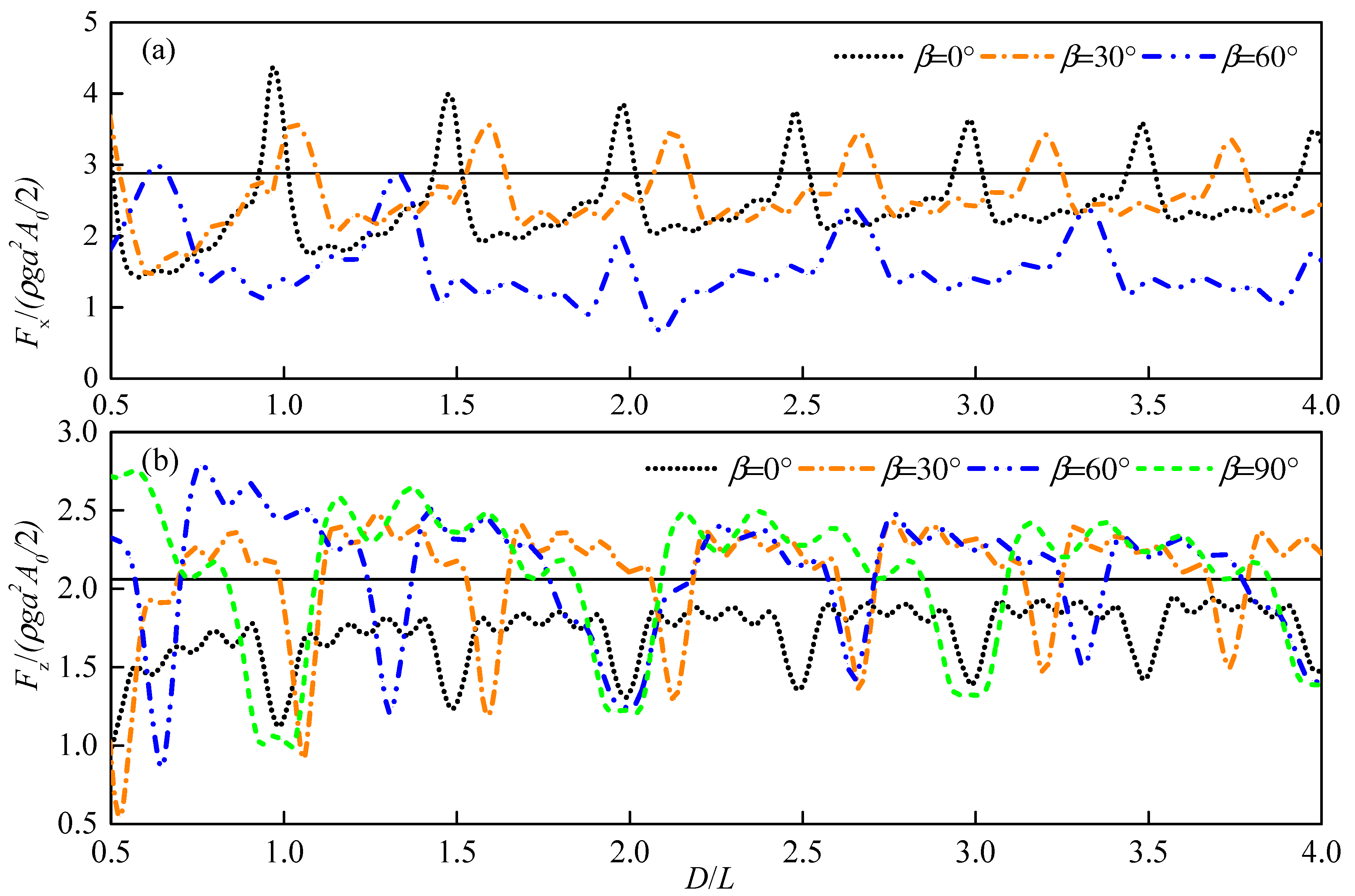
The variation of the excitation force with the dimensionless spacing D/L (L is the wavelength), under different incident wave directions is investigated and shown in Figure 7. The considered wavelength is L = 6.85 m and the range of the spacing is 0.5L < D < 4L. The dimensionless excitation forces on the single isolated absorber in open water in the x-direction and z-direction are 2.88 and 2.06, respectively. It can be seen that the near trapping phenomenon occurs when the ratio of the spacing between the adjacent absorbers and the wavelength meets the certain conditions, which is varied according to the incident wave direction. Figure 7 shows that the periodicity of critical spacing around the near trapping increases with the increase of the incident angle. Thus, the near trapping occurs generally for the oblique incident angle, which was pointed out by Maniar and Newman [9]. In addition, with the increase of the spacing between adjacent absorbers, the overall variation trend of excitation force amplitude is close to the excitation force on the single isolated absorber in open water, which also indicates that the interaction between absorbers decreases.

3.2. Captured Power

The effects of near trapping on the wave-power extraction are investigated in this section. The total power and power fluctuation of a WEC array are mainly concerned in the most previous studies. However, the actual performance of each device may differ greatly from the potential of the power generation, due to the mass production and installation of WEC devices in the array. As a result, not only the total power but the power distribution in the array are taken into account in this section. There are two criteria used for judging the efficiency of the array layout. Firstly, the mean power of the array is greater than or close to the optimal power of the single isolated WEC in open water. Secondly, the power distribution among the WECs is supposed to be uniform, and each WEC plays the full role, i.e., the single interaction factor of each WEC larger or close to 1.0.

3.2.1. Incident Wavelength

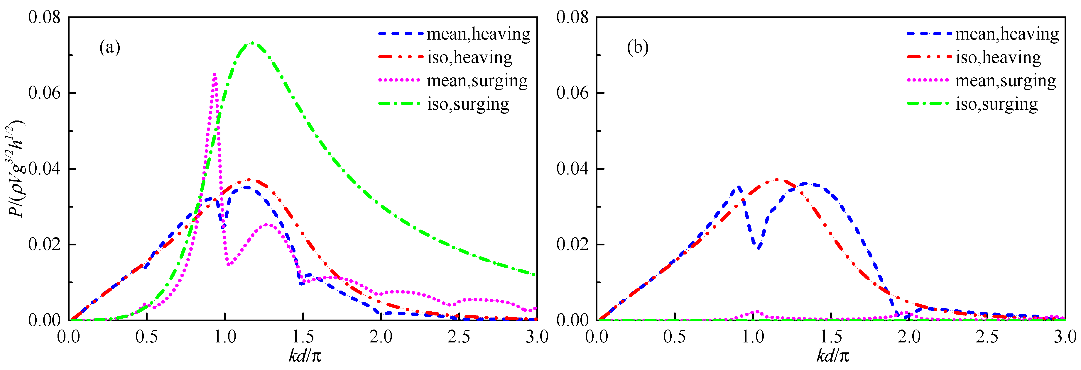
Figure 8 shows the comparison of mean power extracted by the surging and heaving arrays with the power of the single isolated WEC under the incident direction β = 0° and β = 90°. From Figure 8a, it can be seen that the mean power of the array appears to have an extreme value at kd/π ≈ n/2, in a heaving or surging array. The mean power is affected by Neumann-type and Dirichlet-type near trapping at kd/π ≈ n/2 and kd/π ≈ n (n = 1, 2, …), respectively. At kd/π ≈ 1.0 and 1.5, the mean power of surging array is reduced by about 75% and 80% in comparison with the single isolated one, respectively. At the same time, the relating reductions of mean power in the heaving array are 30% and 55%, respectively. This shows that when the near trapping phenomenon occurs, the total power of the array decreases significantly and the effect of near trapping on the surging array is more dramatic than that on the heaving array. Moreover, for the long wavelength, there is basically no difference between the mean power and the power absorbed by the single isolated absorber and the array. However, for the short wavelength, the absorbed power changes significantly because the interference between the array and wave becomes more remarkable. As shown in Figure 8b, the mean power of the array is only affected by Dirichlet-type near trapping at kd/π ≈ n, where Dirichlet boundary condition is satisfied. The mean power of the surging array is basically near to 0, because the original PTO damping (parallel to the x-axis and 0-degree incident direction) is orthogonal to the incident wave direction at this time.
For the single isolated absorber in open water, the power captured in surge mode is twice as much as that in heave mode, and the frequency adaptability of power is better for the single isolated absorber in surge mode. However, when the surging absorbers are arranged into the linear array, the incident wave frequency and direction adaptability of total power are quite poor. In contrast, the frequency and direction adaptability of the power extracted by the heaving array have little change compared with that of the single isolated heaving absorber.
As a result, the absorbers oscillating in the surge mode are not suitable in the array system, because interaction effects have a quite negative impact on their performance. Therefore, the heaving arrays should be chosen according to the economy of resource utilization and adaptability to sea conditions.
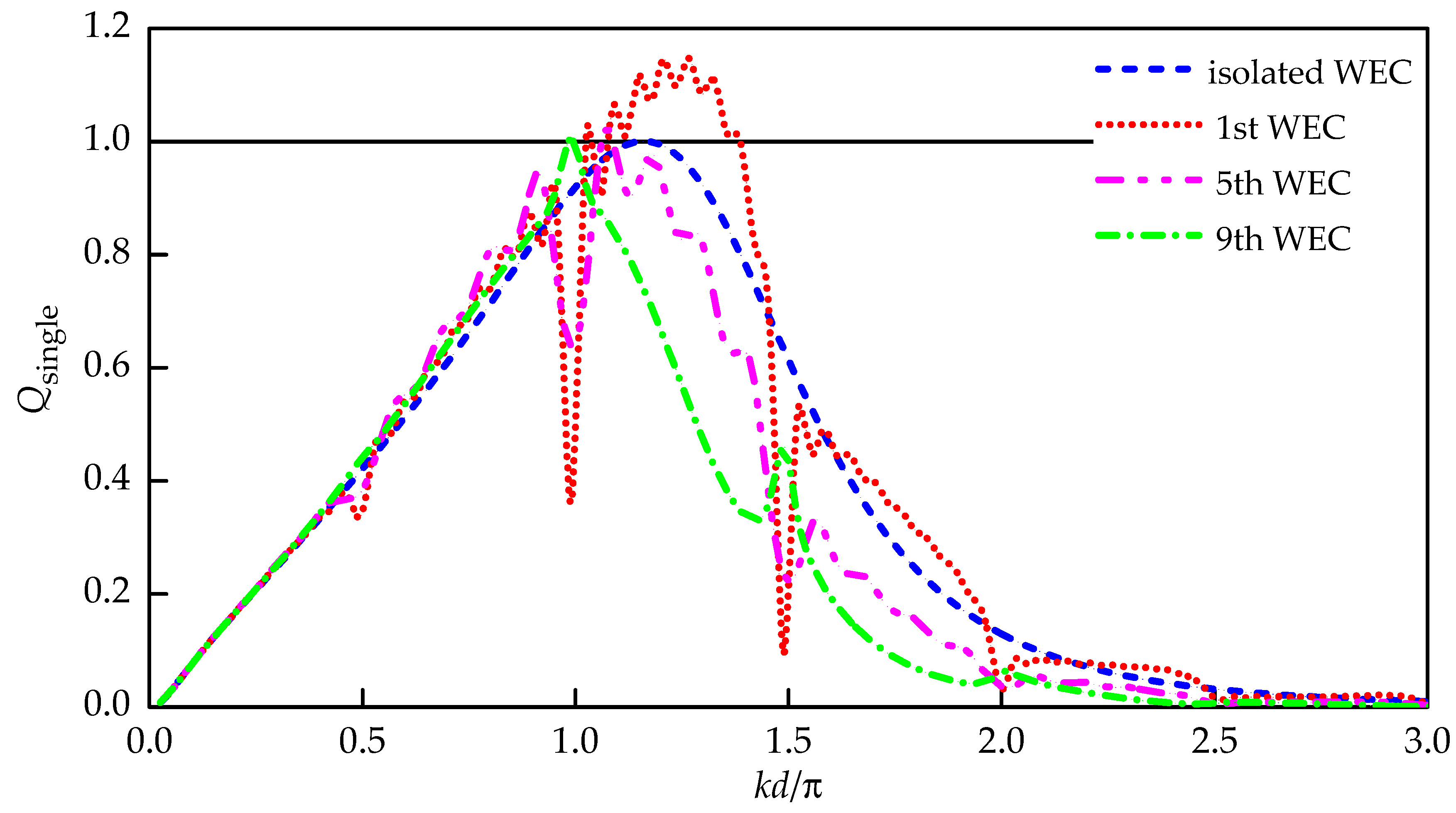
The single interaction factors of three representative WECs in the array and comparison with the single isolated WEC in open water are shown in Figure 9. A series of significant changes can be found at the critical wave numbers at which the near trapping conditions (i.e., kd/π ≈ n/2, n = 1, 2, …) are satisfied. In the long wave, the difference of power captured by all absorbers in the array is very small because of the strong diffraction of the incident energy along the array. Even when Neumann trapping mode occurs (kd/π ≈ 0.5), the power differences among absorbers in the array and that of the single isolated absorber are not very significant. However, when kd/π ≈ 1.0 and 1.5, the effect of near trapping is quite obvious. When kd/π ≈ 1.0, although the power absorbed by the first WEC decreases significantly, the power absorbed by the downstream WECs along the array increases gradually, and the power of 9th WEC is close to the optimal power of the single isolated one in open water. When kd/π > 1.0 and far from the critical wave numbers at which the near trapping occurs, the single interaction factor of each absorber along the array decreases gradually, and the power absorbed by the first WEC is the largest. This is mainly due to the reflection from the downstream absorber, which can make the upstream absorber extract more power. Meanwhile, the power extracted by the downstream absorber is obviously lower than the power extracted by the single isolated absorber in open water due to the absorption and dissipation of the incident energy by the upstream absorber.
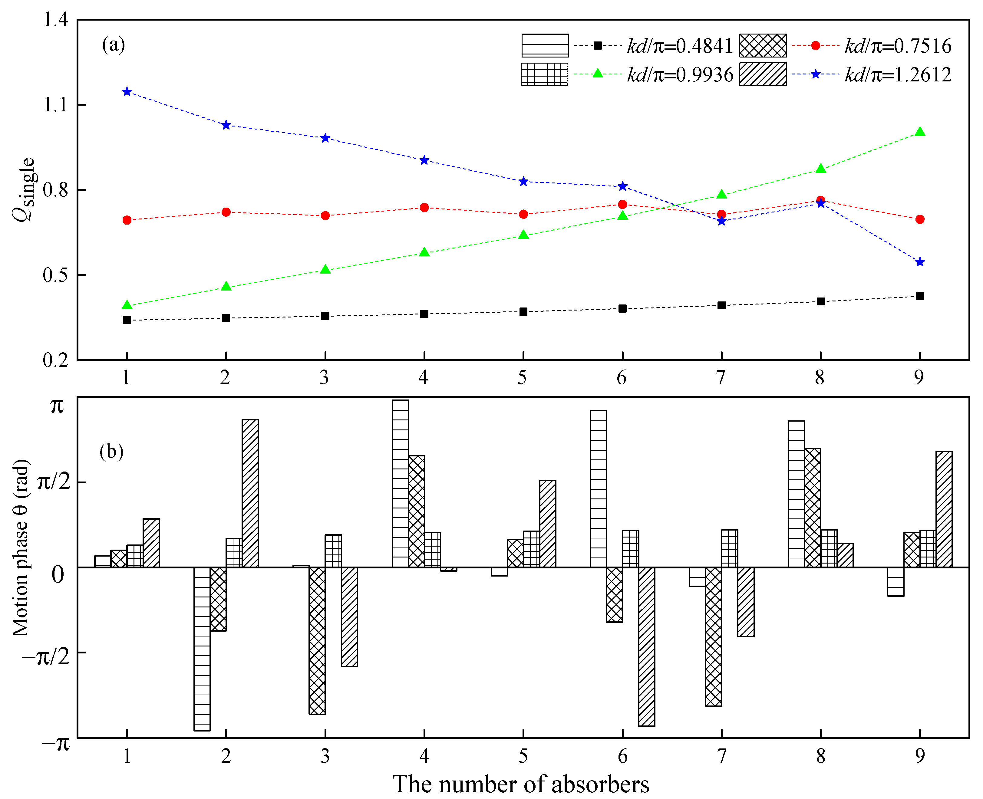
In other words, as the near trapping occurs, the incident energy is affected by the array and transformed to the array downstream and the power extraction increases along the array distribution. For the cases without near trapping, the power extracted by the upstream WECs is large. Figure 10 shows the distribution of the single interaction factor and motion phases of nine heaving absorbers in the head seas, under four incident wave conditions, which were selected according to the results in Figure 9, including the critical frequencies of Neumann-type and Dirichlet-type near trapping. The other two cases are kd/π = 0.7516 and kd/π = 1.2612.
Unsurprisingly, when the spacing between absorbers remains fixed, the motion and power absorbed by each absorber in the array are closely related to the wavelength. In the first case of kd/π = 0.4841, due to the influence of Neumann trapping and strong wave diffraction, the incident energy is refracted to the interior of the array, and the single interaction factor along the array increases slightly. Moreover, it can be seen from Figure 10b that the motion on the adjacent absorbers has the opposite phase. In the second case of kd/π = 0.7516, where the spacing is three times the quarter-wavelength, the power is basically consistent along the array, and slightly larger in the middle, which should be caused by the reflection effects of the downstream absorbers. The phase difference of the adjacent absorbers is about ±π/2. In the third case of kd/π = 0.9936, where the wavelength is approximately equal with the spacing, the Dirichlet boundary condition can be satisfied. Therefore, the motion phase of each absorber is basically the same. Just like Neumann trapping, the incident energy is refracted into the interior of array. Due to the redistribution of the incident energy by trapping, the single interaction factors along the array are markedly increased, and the power extracted by the last absorber approaches that of the single isolated absorber. In the case of kd/π = 1.2612, the diffraction effects are weakened and the sheltering effects are strengthened because the absorber scale relative to the wavelength is larger. Thus the single interaction factor decreases along the array. The motion phase difference of the adjacent absorbers is the same as kd/π = 0.7516.
From these four cases, it can be seen that the ratio of the spacing and the wavelength has a significant effect on the whole performance of the array. The wave energy distribution can change due to the action of the array. Therefore, it is necessary to discuss the effect of the relative spacing on the array performance in detail.

3.2.2. Spacing between Absorbers

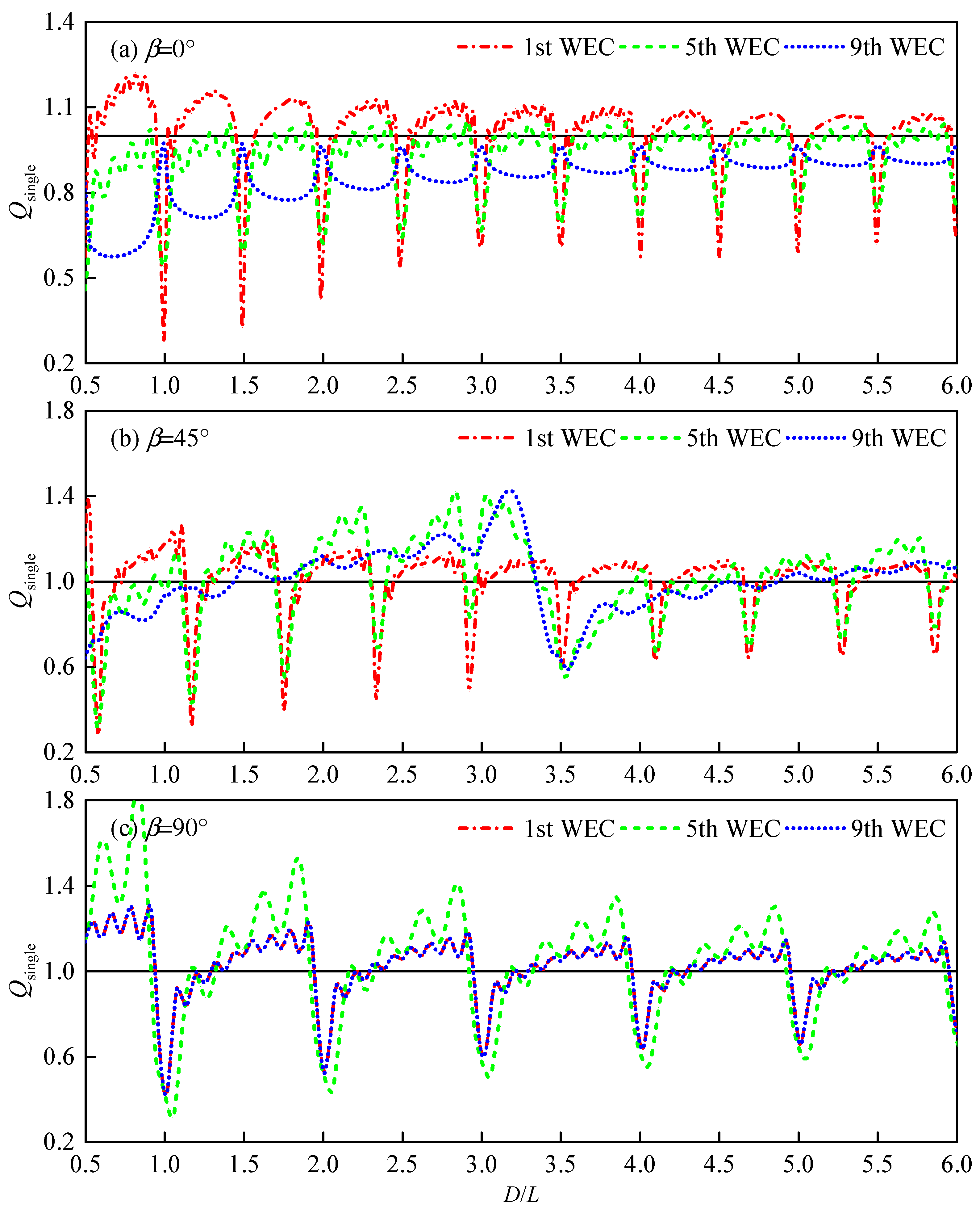
In this section, the influence of the spacing between the adjacent absorbers on the power distribution in the array under different incident wave directions is studied, as shown in Figure 11, where the horizontal solid line represents the single interaction factor of the single isolated absorber in open water. The influence of the ratio of spacing to wavelength on the absorbed power is considered and the wavelength is kept as L = 6.85 m, at which time the power absorbed by the single isolated absorber in open water is optimal.
From Figure 11, it can be seen that the periodicity of the power extracted by the absorbers with respect to spacing is the same with that of the excitation force acting on the absorbers (Figure 7). According to the characteristics of the single interaction factors shown in Figure 11, the facing wave direction and layout spacing of the array can be adjusted to reduce the power difference among absorbers and improve the total power.
At β = 0° in Figure 11a, the power absorbed by the first WEC in the array is smaller than that absorbed by the last WEC when the relative spacing satisfies the certain condition (D/L = n/2, n = 1, 2, …), i.e., near trapping condition, at which the captured power increases along the incident wave direction. However, the absorbed power of each absorber decreases along the incident wave direction at the none near trapping condition. The power absorbed by each WEC in the array is quite different and the power distribution is uneven, which indicates that the array layout is not desirable.
At β = 90° in Figure 11c, the near trapping occurs when the spacing is equal to the integral times of the wavelength (i.e., D/L = n, n = 1, 2, …), at which the single interaction factor of each WEC decreases significantly. In the absence of near trapping, the overall trend of the power absorbed by each WEC is basically the same. Moreover, the single interaction factor of the middle WEC is slightly higher than that of other WECs, and the single interaction factors of all WECs may be above 1.0. The array layout is more reasonable with this status. Therefore, the total power absorbed by the array is the least and the performance is the worst when the arrangement spacing is equal to the integer times the wavelength. In contrast, when the spacing is far from these separation spacings inducing the near trapping, the single interaction factor of each WEC may be more than 1.0, and the performance could be greatly improved due to the beneficial interaction.
At β = 45° in Figure 11b, the near trapping occurs at D/L ≈ 0.6n (n = 1, 2, …). In addition, the uniformity of power distribution along array is between β = 0° and β = 90°. Beyond the separation spacings inducing the near trapping, the interaction factor of the upstream absorber decreases with the spacing, while those of the middle and downstream absorbers increase in the spacing range from 0.5 L to 3.5 L and from 3.5 L to 6.0 L. These two spacing ranges can be regarded as two large envelopes, during which there exists a certain periodicity. The periodicity of this large envelope depends on the incident direction, and the details are described in the Section 3.2.4.

3.2.3. Number of Devices

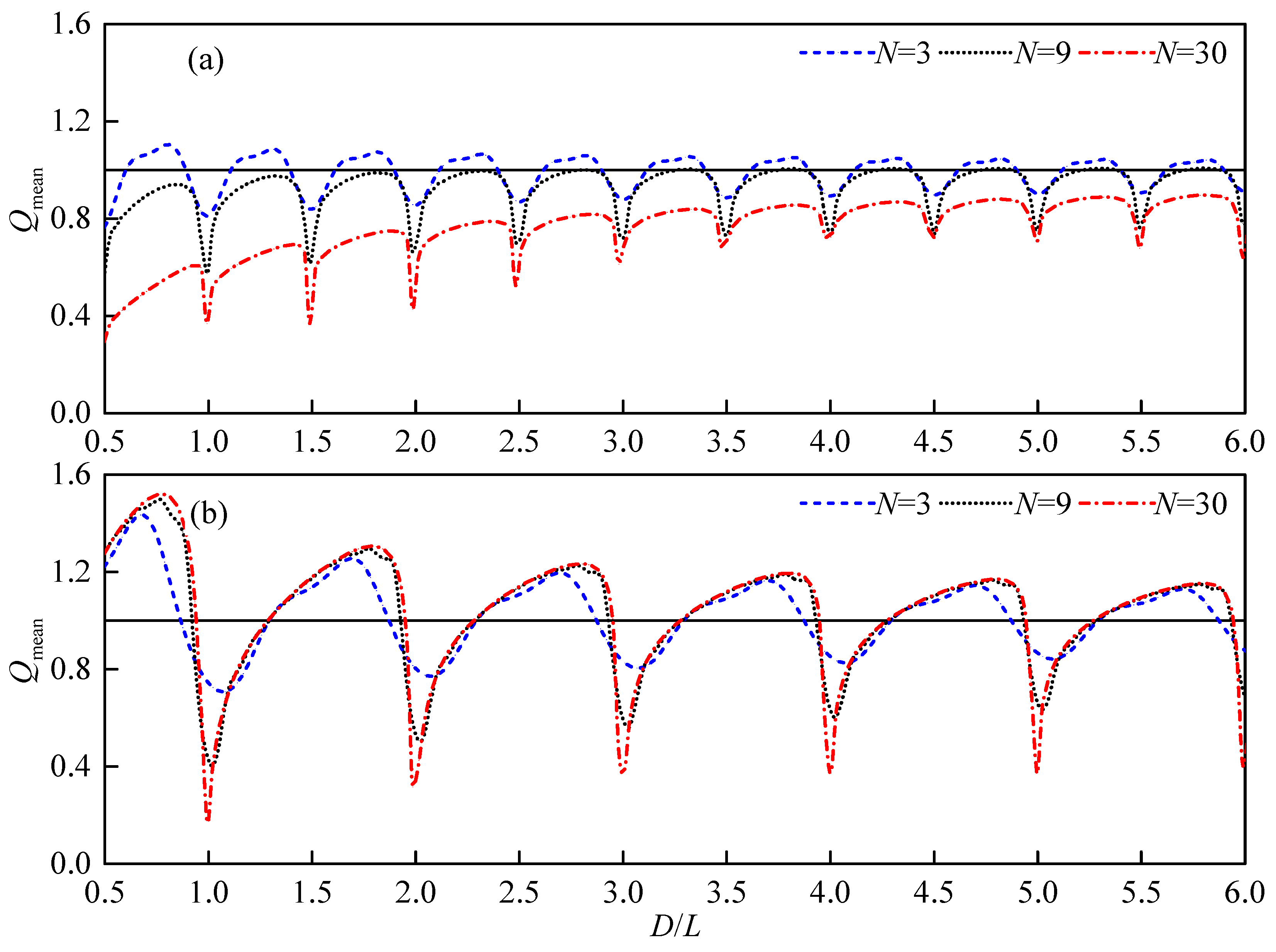
The above results are the analysis of the influence of the near trapping on the array performance based on the single interaction factor. The effects of the number of WECs on the mean interaction factor in the array is studied in this section. The relating results are shown in Figure 12.
For all the arrays studied, at the near trapping conditions, i.e., D/L = 0.5n (β = 0°) and D/L = n (β = 90°), the mean interaction factor significantly decreases to the trough, which further indicates that the near trapping phenomenon can reduce the total power of the array. And near these special spacings, the mean interaction factor decreases with the increase of the number of WECs, indicating that the near trapping is closer to the ideal trapping phenomenon.
The mean interaction factor of the array is constructive at most of the none near-trapping spacing for β = 0° and N = 3, which indicates that the interaction can increase the power extracted by the array. With the number of WECs increasing, the mean interaction factor decreases gradually. Therefore, it is not appropriate to arrange more WECs along the incoming wave direction, which is in agreement with earlier studies [5]. However, for the case of β = 90°, the interaction between arrays increases the power extracted by the array for both the smaller and larger arrays. With the number of absorbers increasing, the advantageous spacing range is broadened slightly and the constructive interaction factor increases slightly before the near trapping occurs, as shown in Figure 12b.
For larger arrays, the reduction of the total power due to the near trapping is greater. Thus the array spacing should be designed to avoid the range where near trapping may occur. In addition, for more absorbers arranged along the incidence wave direction, the shadowing effect implies the reduction of the total power absorbed by the array.

3.2.4. Incident wave Direction

The above discussion shows that the incident wave direction affects the hydrodynamic performance of the array, that is, not only does the spacing of the near trapping change, but also a periodic large envelope occurs. The influence of the wave direction is described in this section.
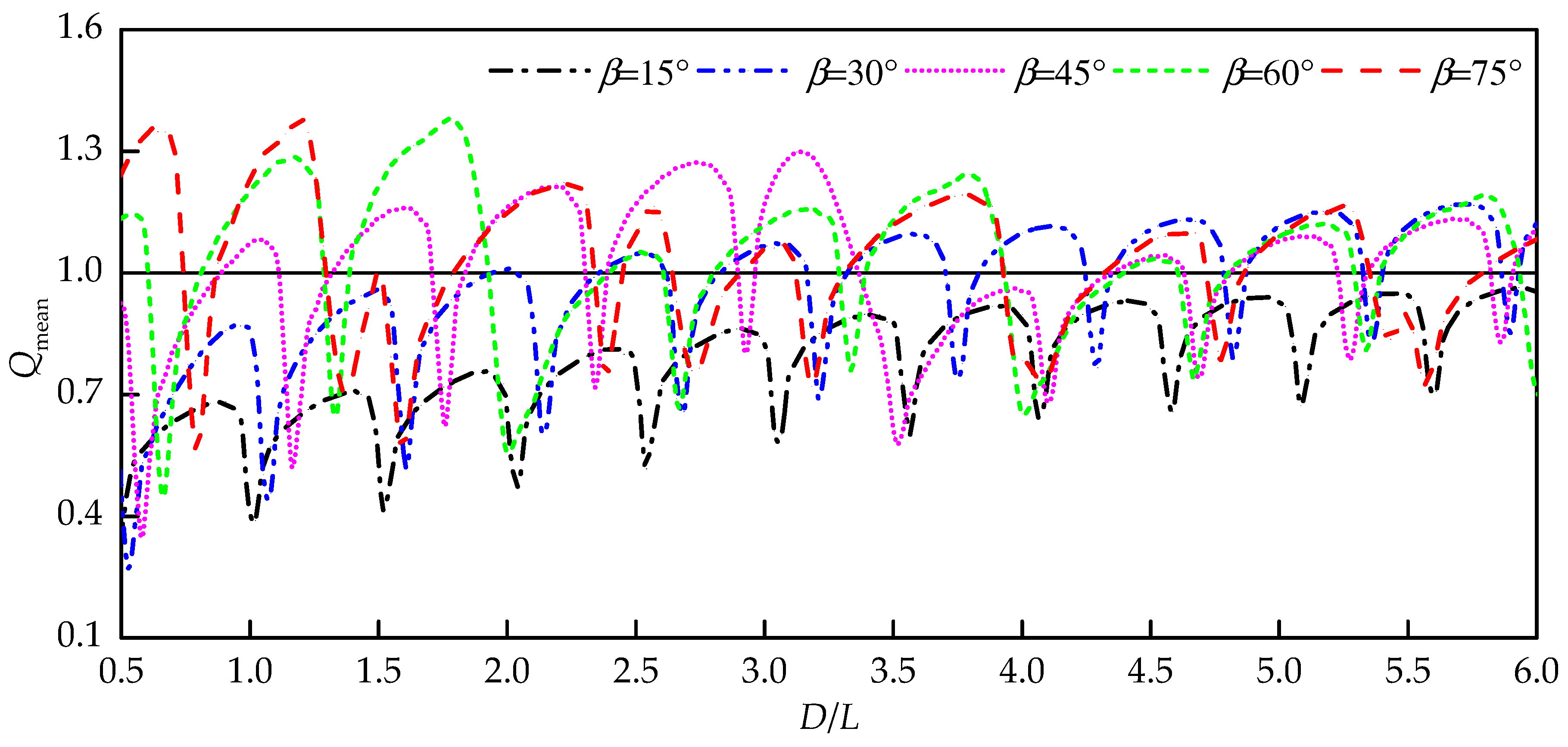
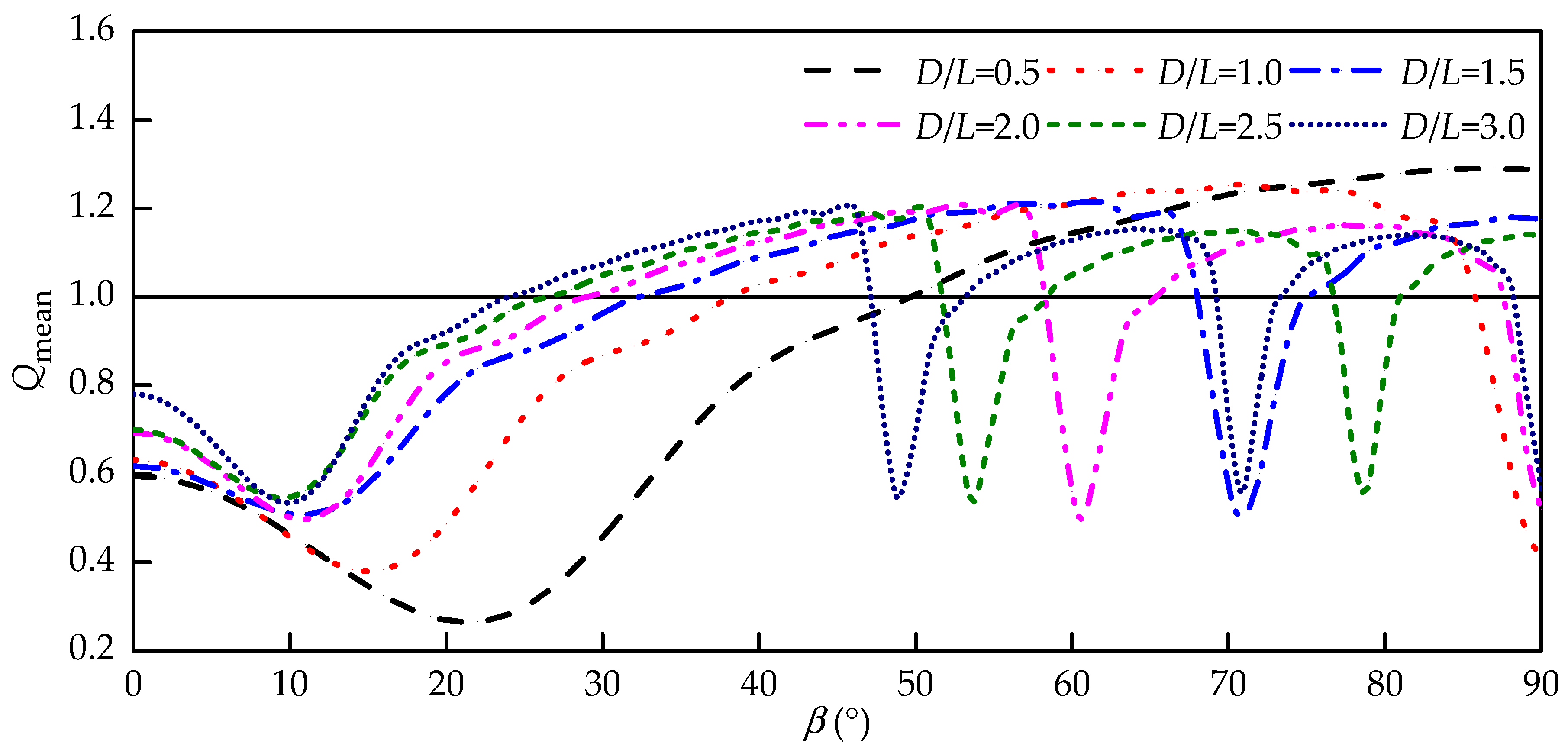
In Figure 13, the mean interaction factor is given as the function of the relative spacing between the adjacent absorbers for the incident wave direction varied from β = 15° to β = 75°, and the angle step is 15°. It can be found that the spacing where the near trapping occurs increases with the incident angle. Therefore, at the same spacing, the array performance of different incident directions may vary greatly. For instance, when the spacing is equal to the wavelength (D = L), the mean interaction factors of the array at β = 60° and 75° are more than 1.2 times that of the single isolated absorber, while the mean interaction factors at β = 0°, 15°, 30° and 90° are obviously less than 1.0.
Combined with the cases of N = 9 in Figure 12, there are only several periodic separation spacings satisfying Qmean > 1 after D > 3L in head seas, and the interaction effects are always constructive except for the spacing range (D/L = 0.93 + n − 1.29 + n, n = 1, 2, …) inducing the near trapping in beam seas. The near trapping can reduce the power production by more than 40% (for head seas) and 60% (for beam seas) in comparison with the single isolated absorber at the spacing D = L. For the incident directions other than β = 0° and β = 90°, the periodic envelopes appear on the curves of interaction factors related to the spacing. The maximum amplitude of this envelope decreases as the spacing increases, and the envelope period decreases with the increase of the incident wave angle.
From Figure 14, it can be seen that if the relative spacing remains constant, the array performance varies with the incident angle. By taking D/L = 0.5 as an example, the minimum value of the mean interaction factor appears near β = 22°, while the mean interaction factor is greater than 1.0 for β ≥ 52°. For the case of D/L = 1.0, the mean interaction factor has minimum value at β = 15°and 90°, while the mean interaction factor is greater than 1.0 for β = 40°–85°. Generally, a small incident angle is not constructive for the total power extraction, especially for the array layout with small spacing, which is expected due to shadowing effects. A large incident direction angle is therefore beneficial to the array performance, except for those inducing the near trapping.
As shown in Figure 14, there is only one direction angle inducing the near trapping at D/L = 1.5, while there are three directional angles causing the near trapping at D/L = 3.0. With the increase of the separation spacing, the number of incident direction angles inducing the near trapping increases. For larger spacing, the first incident direction angle inducing the near trapping grows smaller, which is related to the occurrence of envelope. In other words, with the spacing increasing, the direction angle at which the mean power of the array is equal to the power of the single isolated WEC in open water becomes smaller. Figure 14 shows that the first sudden change occurs at β = 60° for D/L = 2.0. Combined with Figure 13, D = 2L is the period of large envelope in this incident direction. So for β = 60°, there are three such envelopes appearing in the range of spacing studied, and the maximum amplitude of envelope decreases because of the weakened interaction. For β = 45°, the period of envelope is D = 3.5L as shown in Figure 13, which corresponds to the first direction angle inducing the near trapping at D/L = 3.5 according to Figure 14.
It can be seen that, once the array layout and incident condition are constant, the direction angle of the array layout relative to the incident wave can also be adjusted to improve the performance of the array. The effect of the direction, therefore, provides an opportunity to uniformly distribute power in the array and improve power characteristics.

4. Summary and Conclusions

The connection between the near trapping phenomenon and the excitation force and power extracted by the linear periodic WEC array in open water is investigated in this paper, and the following conclusions are obtained.
The excitation force crest in the x-direction and the trough in the z-direction, occurring at the critical dimensionless wave numbers and spacings, are induced by the near trapping. The dimensionless spacing (D/L) cycle of the near trapping increases from 0.5 to 1.0 with the increase of the incident angle from β = 0° to β = 90°, due to the fact that only the Dirichlet boundary condition is satisfied at beam seas.
The power extracted by the surging and heaving array is analyzed, respectively. Although the frequency adaptability and the power absorbed by the surge motion are much better than those of the heave motion in comparison with the single isolated absorber in open water, the surging array does not perform well for three reasons: The effective frequency bandwidth becomes narrow. The maximum captured power deviates from the optimal state of the single isolated absorber. Finally, the direction adaptability of the surging absorber is much worse than that of the heaving absorber. Therefore, the arrays of heaving WECs is preferable.
The single interaction factor and mean interaction factor of the heaving arrays are discussed in detail with respect to the separate spacing, number of WECs, and incident wave direction. It is found that the near trapping not only significantly reduces power production, but also changes the power distribution. When the near trapping occurs, the single interaction factor increases along the array. Thus the power extracted by the back-end WEC in the array is larger than that of the upstream absorbers. Near trapping significantly reduces the mean interaction factor of the array, especially for the cases with a large number of absorbers. Thus the separation spacing inducing the near trapping should be avoided in the designed array. For the cases of no near trapping, the number of WECs arranged along the incident wave direction should not be too large, because the power extracted by the downstream WECs reduces. While the array is arranged perpendicular to the incident wave direction, the number of WECs will not significantly affect the total power of the array.
The incident direction angle also has an important influence on the array effect. For the small incident angle, the efficiency of power extraction is poor, especially for the array layout with the small spacing. For the spacing among absorbers inducing the near trapping, the array performance can be improved by adjusting its direction angle relative to incident waves. For the incident directions except for β = 0° and β = 90°, some periodic envelopes appear on the curves of the interaction factors. These envelopes depend on the incident wave angle and offer some possibilities to uniformly distribute the power in the array and improve power characteristics.
It is worth noting that the realistic ocean waves are multi-directional and the predominant wave directions change over time, which suggests that the optimal array layout in the certain wave conditions may be suboptimal in other cases. Therefore, the performance of the large arrays under the realistic ocean waves and the influence of the near trapping on the absorbed power deserve further investigation.

Author Contributions

All authors have contributed to the development of the research and in the elaboration of this article. Specifically, D.N. and Y.G. contributed to the methodology; Z.H. carried the numerical simulation and draft the manuscript; D.N., Y.G. and M.G. reviewed and edited the manuscript. All authors have read and agreed to the published version of the manuscript.

Funding

This research was funded by the international collaboration and exchange program from the NSFC-RCUK/EPSRC (Grant number 51761135011) and the National Natural Science Foundation of China (Grant number 51679036).

Conflicts of Interest

The authors declare no conflict of interest.

References

  1. Zhong, Q.; Yeung, R.W. Wave-body interactions among energy absorbers in a wave farm. Appl. Energy 2019, 234, 1051–1064. [Google Scholar] [CrossRef]
  2. Göteman, M. Wave energy parks with point-absorbers of different dimensions. J. Fluids Struct. 2017, 74, 142–157. [Google Scholar] [CrossRef] [Green Version]
  3. Mcguinness, J.P.L.; Thomas, G. Hydrodynamic optimisation of small arrays of heaving point absorbers. J. Ocean Eng. Mar. Energy 2016, 22, 1–19. [Google Scholar] [CrossRef] [Green Version]
  4. Andrés, A.D.D.; Guanche, R.; Meneses, L.; Vidal, C.; Losada, I.J. Factors that influence array layout on wave energy farms. Ocean Eng. 2014, 8282, 32–41. [Google Scholar] [CrossRef]
  5. Göteman, M.; Engström, J.; Eriksson, M.; Isberg, J.; Leijon, M. Methods of reducing power fluctuations in wave energy parks. J. Renew. Sustain. Energy 2014, 6, 043103. [Google Scholar] [CrossRef] [Green Version]
  6. Stratigaki, V.; Troch, P.; Stallard, T.; Forehand, D.; Folley, M.; Kofoed, J.P.; Benoit, M.; Babarit, A.; Vantorre, M.; Kirkegaard, J. Sea-state modification and heaving float interaction factors from physical modelling of arrays of wave energy converters. J. Renew. Sustain. Energy 2015, 7, 061705. [Google Scholar] [CrossRef] [Green Version]
  7. Evans, D.V.; Linton, C.M. Trapped modes in open channels. J. Fluid Mech. 1991, 225, 153–175. [Google Scholar] [CrossRef]
  8. Evans, D.V.; Levitin, M.; Vassiliev, D. Existence theorems for trapped modes. J. Fluid Mech. 1994, 261, 21–31. [Google Scholar] [CrossRef] [Green Version]
  9. Maniar, H.D.; Newman, J.N. Wave diffraction by a long array of cylinders. J. Fluid Mech. 1997, 339, 309–330. [Google Scholar] [CrossRef]
  10. Evans, D.V.; Porter, R. Near-trapping of waves by circular arrays of vertical cylinders. Appl. Ocean Res. 1997, 19, 83–99. [Google Scholar] [CrossRef]
  11. Walker, D.A.G.; Eatock Taylor, R. Wave diffraction from linear arrays of cylinders. Ocean Eng. 2005, 32, 2053–2078. [Google Scholar] [CrossRef]
  12. Siddorn, P.; Eatock Taylor, R. Diffraction and independent radiation by an array of floating cylinders. Ocean Eng. 2008, 35, 1289–1303. [Google Scholar] [CrossRef]
  13. Wolgamot, H.A.; Eatock Taylor, R.; Taylor, P.H. Radiation, trapping and near-trapping in arrays of floating truncated cylinders. J. Eng. Math. 2015, 91, 17–35. [Google Scholar] [CrossRef]
  14. John, F. On the motion of floating bodies II. Simple harmonic motions. Commun. Pure Appl. Math. 1950, 3, 45–101. [Google Scholar] [CrossRef]
  15. Teng, B.; Taylor, R.E. New higher-order boundary element methods for wave diffraction/radiation. Appl. Ocean Res. 1995, 17, 71–77. [Google Scholar] [CrossRef]
  16. Falnes, J. Ocean Waves and Oscillating Systems; Cambridge University Press: Cambridge, UK, 2002. [Google Scholar]
  17. Bellew, S.; Stallard, T.; Stansby, P.K. Optimisation of a heterogenous array of heaving bodies. In Proceedings of the 8th European Wave and Tidal Energy Conference, Uppsala, Sweden, 7–10 September 2009. [Google Scholar]
  18. Babarit, A. Impact of long separating distances on the energy production of two interacting wave energy converters. Ocean Eng. 2010, 37, 718–729. [Google Scholar] [CrossRef] [Green Version]
Figure 1. The coordinate system of the array.
Sustainability 12 00029 g001
Figure 2. The diagrammatic sketch of 1 × 5 array of hemispheres in reference [17].
Sustainability 12 00029 g002
Figure 3. Comparison of the present mean interaction factor with the results in reference [17].
Sustainability 12 00029 g003
Figure 4. Schematic representation of the linear array composed of nine truncated cylinders.
Sustainability 12 00029 g004
Figure 5. Schematic representation of the heaving (a) and surging (b) wave energy converters (WEC).
Sustainability 12 00029 g005
Figure 6. Comparison of the normalized excitation forces on the middle cylinder of the array with those on the single isolated cylinder in open water.
Sustainability 12 00029 g006
Figure 7. Variation of excitation-force amplitudes in the x-direction (a) and z-direction (b) acting on the middle absorber with the relative spacing for different incident directions and comparison with the load on the single isolated cylinder (horizontal solid line).
Sustainability 12 00029 g007
Figure 8. Comparison of the normalized mean power extracted by the heaving array (dash line) and surging array (dot line) with the power of the single isolated heaving absorber (two-dot chain line) and surging absorber (chain line) in head (a) and beam (b) seas.
Sustainability 12 00029 g008
Figure 9. Comparison of the single interaction factors of the 1st, 5th and 9th WECs in the heaving array for β = 0° with the single isolated WEC in open waters.
Sustainability 12 00029 g009
Figure 10. Distribution of the single interaction factor (a) and motion phase (b) along the linear array of nine heaving absorbers with D = 8a in the head seas. The absorbers are identified by the abscissa, with the first absorber at the up-wave end of the array.
Sustainability 12 00029 g010
Figure 11. Single interaction factor of the 1st, 5th and 9th WECs in the array with the dimensionless spacing at β = 0°, 45°and 90°.
Sustainability 12 00029 g011
Figure 12. Variation of the mean interaction factor with the relative spacing for different number of WECs in the head (a) and beam (b) seas.
Sustainability 12 00029 g012
Figure 13. Variation of the mean interaction factor of the array with the relative spacing for different incoming wave directions.
Sustainability 12 00029 g013
Figure 14. Variation of the mean interaction factor of array with the incident wave angle for different spacing.
Sustainability 12 00029 g014