Article

Investigation of Interference Effects Between Wind Turbine and Spar-Type Floating Platform Under Combined Wind-Wave Excitation

School of Naval Architecture, Ocean and Civil Engineering, State Key Laboratory of Ocean Engineering, Shanghai Jiao Tong University, Collaborative Innovation Centre for Advanced Ship and Deep-Sea Exploration, Shanghai 200240, China
*
Author to whom correspondence should be addressed.
Sustainability 2020, 12(1), 246; https://doi.org/10.3390/su12010246
Submission received: 1 December 2019 / Accepted: 20 December 2019 / Published: 27 December 2019

Abstract

:
In order to further understand the coupled aero-hydrodynamic performance of the floating offshore wind turbine (FOWT) in realistic ocean environment, it is necessary to investigate the interference effects between the unsteady aerodynamics of the wind turbine and different degree-of-freedom (DOF) platform motions under combined wind-wave excitation. In this paper, a validated CFD analysis tool FOWT-UALM-SJTU with modified actuator line model is applied for the coupled aero-hydrodynamic simulations of a spar-type FOWT system. The aero-hydrodynamic characteristics of the FOWT with various platform motion modes and different wind turbine states are compared and analyzed to explore the influence of the interference effects between the wind turbine and the floating platform on the performance of the FOWT. The dynamic responses of local relative wind speed and local attack angle at the blade section and wind-wave forces acting on the floating platform are discussed in detail to reveal the interaction mechanism between the aerodynamic loads and different DOF platform motions. It is shown that the surge motion and the pitch motion of the floating platform both significantly alter the local attack angle, while only the platform pitch motion have significant impacts on the local relative wind speed experienced by the rotating blades. Besides, the shaft tilt and the pro-cone angle of the wind turbine and the height-dependent wind speed all contribute to the variation of the local attack angle. The coupling between the platform motions along different DOFs is obviously amplified by the aerodynamic forces derived from the wind turbine. In addition, the wake deflection phenomenon is clearly observed in the near wake region when platform pitch motion is considered. The dynamic pitch motion of the floating platform also contributes to the severe wake velocity deficit and the increased wake width.

1. Introduction

Limited by the space availability, noise restriction, visual pollution and regular problems, the exploration of wind energy is advancing from the land to the offshore area and further to the deep sea [1]. The offshore wind turbines with larger capacity have gradually become the research focus in wind power industry. Considering that the cost of offshore wind turbines mounted on the bottom-fixed structures increases sharply with water depth, the offshore wind turbines supported by the floating structures, known as the floating offshore wind turbines (FOWTs), are believed to be the most economical choice in deep waters [2,3]. However, although the concept of FOWT has been proposed for decades, there are still several technique difficulties to be solved before the large-scale commercial application of the FOWT. One of the most challenging issues is how to achieve the dynamic stability of the FOWT under complicated wind-wave-current loads in realistic ocean environment. It is known that there are strong interactions between the wind turbine and the floating support platform when the FOWT is in operation [4]. On the one hand, the aerodynamic forces derived from the wind turbine will act on the floating platform and greatly change the motion responses. On the other hand, the six-degree-of-freedom (6DOF) platform motions also affect the rotating blades and significantly alter the aerodynamic performance. Thus, the interference effects between the wind turbine and the floating platform make the coupled aero-hydrodynamic characteristics more complicated and lead to increased instability of the FOWT system. In order to better understand the coupling phenomena and contribute to the realization of the dynamic stability of the FOWT, it is necessary to investigate the interference effects between the wind turbine aerodynamics and different degree-of-freedom (DOF) platform motions.
A number of researches have been carried out to focus on the impacts of platform motions on the aerodynamic loads and the turbine wake. The vortex method using lift lines or surfaces to represent rotor blades can capture the three-dimensional (3D) flow details around the turbine blades and has advantages in predicting flow development, which are widely applied in the unsteady aerodynamics prediction of the FOWT [5]. Besides, the software WInDS based on the Free Vortex Method (FVM) was developed for the FOWT [6,7]. Wen et al. [8,9] investigated the influence of platform surge and pitch motion on the dynamic responses of aerodynamic loads using the FVM. The reduced frequency was proposed to describe the combined influence of the frequency and the amplitude of platform motion on the aerodynamic performance. It was found that the mean power output changed in the opposite trend at different tip speed ratios when the reduced frequency increased, while the variation amplitudes of aerodynamic loads increased with the increase of the reduced frequency at all tip speed ratios. In addition, the computational fluid dynamics (CFD) approach, which inherently considers the flow viscosity, is also utilized to perform full-scale simulations for the FOWT and model the dynamic interactions among fluid flow, wind turbine and floating platform [10]. Tran et al. [11,12,13] conducted a series of CFD simulations for the FOWT with different prescribed platform motion modes. The impacts of periodical surge, pitch and yaw motions on the wind turbine aerodynamic characteristics were discussed in detail. It was found that the aerodynamic loads were sensitive to changes in the frequency and amplitude of platform motion, especially pitching motion. Lei et al. [14] studied the aerodynamics of a scale vertical axial wind turbine in pitching motion by applying CFD method with improved delayed detached eddy simulation. It was shown that the platform pitch motion can improve the aerodynamic power output and enlarge the variation range of aerodynamic force coefficient. Liu et al. [15] analyzed the aerodynamic performance of NREL Phase VI wind turbine with prescribed platform motions based on the OpenFOAM. Different DOF platform motions including surging, pitching and yawing all showed significant effects on the power output and thrust. Li et al. [16] modified the conventional actuator line model (ALM) to predict the unsteady aerodynamics of the FOWT.
The studies about the influence of aerodynamic loads on the hydrodynamic responses of the FOWT were also conducted. It was noted that the aerodynamic forces were usually simplified into time-independent forces in the research of hydrodynamic performance of the FOWT. Therefore, the interference effects between the wind turbine and the floating platform were neglected. Ma et al. [17] explored the influence of the aerodynamic loads on the hydrodynamic responses of a spar-type floating platform under extreme sea states using FAST code. The low frequency motions were dominantly influenced by the wind loads. Zhao and Wan [18] studied the motion responses of a semi-submersible platform with different wind turbine states in different regular waves, and the same platform was also studied in the Offshore Code Comparison Collaboration Continuation (OC4) project [19]. The impacts of wind turbine on platform motions were achieved by imposing equivalent forces and moments on the rotational center of floating platform. The platform pitch motion was found to be greatly influenced by the wind turbine at high wind speed. Antonutti et al. [20,21] applied the CALHYPSO (CALcul HYdrodynamique Pour les Structures Offshore) program for time-domain simulations of a semi-submersible floating wind turbine to investigate the hydrodynamic behaviors under wind and wave loads. The influence of relative direction between the wind and the wave on the platform motion modes was discussed. The in-plane platform motions including surge, heave and yaw were shown to be greatly altered by the misaligned incident wind and waves. Philippe et al. [22] investigated the impacts of wave direction relative to wind on the dynamic behavior of a FOWT with modal analysis method. Natural frequencies and natural modes of the whole system under various wave directions were calculated and analyzed to detect the coupling among different DOF platform motions. It was shown that natural modes the FOWT system varied with the wave direction. Huang et al. [23] used a two-phase CFD solver to investigate the hydrodynamic responses of a spar-type FOWT under wind and wave loads. The aerodynamic forces imposed on the floating platform were simplified into constant forces and moments. The mean values of the platform motion responses along wind direction were found to be dominantly affected by the aerodynamic loads.
In order to improve the understanding of aero-hydrodynamic responses of the FOWT system in realistic ocean environment, some coupled analysis tools were developed for full-scale simulations of the FOWT under combined wind-wave conditions. Quallen et al. [24] combined a quasi-static crowfoot mooring model with a two-phase CFD solver to study the aero-hydrodynamic performance of the spar-type FOWT system applied in Offshore Code Comparison Collaboration (OC3) project [25] under wind-wave loads. Tran and Kim [26] carried out a CFD analysis for the semi-submersible FOWT using a dynamic fluid body interaction method with overset technique. Coupled aero-hydrodynamic characteristics of the FOWT showed good agreement with the experimental test data. Liu et al. [27] developed a numerical tool based on the OpenFOAM for CFD modelling of the FOWT. The coupled dynamic responses of the OC4 semi-submersible FOWT under different operating conditions were studied. The impacts of aerodynamic loads on the floating support structure were also examined in detail. Cheng et al. [28] embedded a modified ALM into the in-house CFD code naoe-FOAM-SJTU to establish a coupled analysis tool FOWT-UALM-SJTU for full-scale simulations of the FOWT. The aero-hydrodynamic responses calculated by this tool were verified and validated by other numerical results and experiment data. Bae and Kim [29,30,31] performed a lot of coupled dynamic analyses for various different FOWTs with combined FAST-CHARM3D code. Coupled rotor-floater-tether responses, blade-pitch-angle control and the elasticity of rotor and mooring were all taken into consideration in this advanced simulation tool. The interference effects between multiple FOWTs and the impacts of second-order sum–frequency wave excitations on the coupled dynamic performance were also investigated. Besides, the experimental tests in wave basin facilities using various scale models were carried out to verify the numerical simulation results and study the coupled aero-hydrodynamic performance of different FOWT designs [32,33,34,35,36]. Several intermediate-scale FOWT models were also deployed on the ocean coast to meet the requirement of full-sized construction of commercial-scale projects [37].
Moreover, researchers also devoted to the study of control strategy of the FOWT. A number of controllers with different control strategies have been designed to avoid structural resonance [38,39] and reduce platform pitching [40,41]. A periodic state space controller using individual blade pitching was developed to improve the power output [42]. In addition, the coupling effects between the blade-pitch-angle-control and platform motions were also investigated [43]. However, it is challengeable for the controller to balance the performance of fatigue loads, platform motion and aerodynamic loads. The optimal control strategy of the FOWT under wind-wave loads is still under investigation. One of the reasons is that the subtle coupling effects between the wind turbine aerodynamics and the platform motions are still unclear.
Above all, the previous studies mainly focus on the influence of prescribed platform motions on the aerodynamic performance and the impacts of simplified aerodynamic forces on the hydrodynamic responses. Limited researches concentrate on the coupled dynamic interactions between the wind turbine and the floating platform, and the influence of interference effects between single DOF platform motion and unsteady aerodynamic loads on coupled performance of the FOWT are still unclear and remain to be further studied. The present work aims to reveal the interaction mechanism between the aerodynamic loads and different DOF platform motions. Unlike the former researches where the wind turbine aerodynamics are coupled with all the 6DOF platform motions, the interference effects between the aerodynamic loads and different single DOF platform motions are respectively investigated in this paper. A validated two-phase CFD solver FOWT-UALM-SJTU based on the open source platform OpenFOAM is utilized to perform coupled aero-hydrodynamic simulations of a spar-type FOWT under combined wind-wave excitation. Based on the simulation results, the unsteady aerodynamic performance with specific DOF platform motion, the platform motion responses under combined wind-wave conditions and the wake field characteristics are all analyzed in detail. Several conclusions can be drawn from the discussions.

2. Numerical Methods

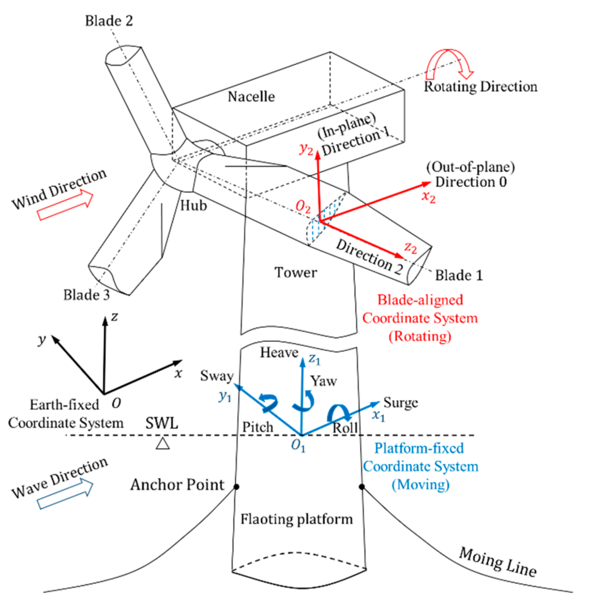
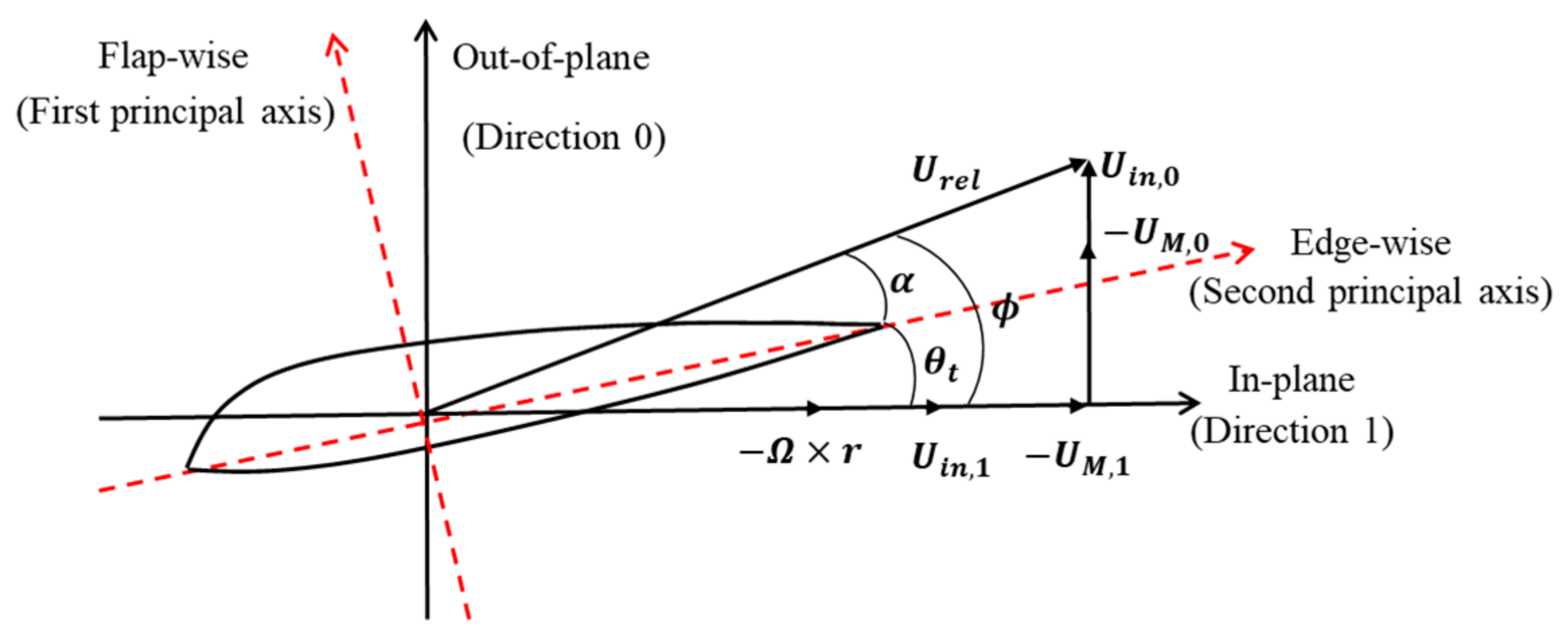
2.1. Inducing 6DOF Platform Motions into ALM

The ALM [44] can effectively achieve the aerodynamic calculations with affordable computational resources and acceptable accuracy. The real wind turbine blades are replaced with virtual actuator lines and further discretized into a series of actuator points withstanding body forces in the ALM, so the blade geometry layer is not required to be solved and computational resources can be greatly reduced. Moreover, the aerodynamic forces are calculated according to the local relative wind speed at the blade section and two-dimensional airfoil profile data obtained from experiments. Then the body forces smeared by a regularization kernel function are introduced into the moment equations to reproduce the turbulent wake flow.
The original ALM cannot be directly applied to predict the aerodynamic performance of the FOWT because of the 6DOF motions of floating support platform. As illustrated in Figure 1, 6DOF motions induced by the combined wind-wave loads will introduce an additional velocity for the rotating blades, which further intensify the interactions between the rotating blades and its wake. In the present work, some modifications are made into the initial ALM to take the influence of platform motions on the rotating blades into consideration. This is accomplished by introducing the additional velocity into the calculation of local relative wind speed, knows as unsteady actuator line model (UALM) [16]. In order to clearly describe the modified ALM, three different coordinate systems including the earth-fixed coordinate system, the platform-fixed coordinate system and the blade-aligned coordinate system are defined firstly, shown in Figure 1. It should be noted that each blade has its own blade-aligned coordinate system. In this coordinate system, direction 0 is along the principle axis of main shaft, and direction 2 is the spanwise direction. The vector in direction 1 is the cross product of vectors in the directions of 2 and 0. The velocities, positions and forces in these three coordinate systems can be transformed into each other through transformation matrices.
The displacements and rotations of floating platform in earth-fixed system are defined as η = η 1 , η 2 = x 1 , x 2 , x 3 , ϕ , θ , ψ , standing for motions of surge, sway, heave, roll, pitch and yaw, respectively. Then the additional velocity U M induced by the dynamic motions of floating platform can be determined by the following equation:
U M , i = η ˙ 1 + η ˙ 2 x i x c
where x i and x c are the positions of the ith actuator point and the rotating center in earth-fixed coordinate system, respectively. It needs to be reminded that U M should be projected into the blade-aligned coordinate system before it is introduced into the calculation of local relative wind speed:
U M = J 02 · U M
where J02 is the transformed matrix defined from the earth-fixed coordinate system to the blade-aligned coordinate system. U M donates the additional velocity vector induced by platform motions in the blade-aligned coordinate system.
Furthermore, different velocity components at the blade section in the blade-aligned coordinate system are presented in Figure 2. The local relative wind speed U rel experienced by the rotating blades is calculated according this equation:
U rel = U in , 1 Ω · r + U in , 0 U M
where U in , 0 and U in , 1 are the velocity components of incoming wind speed in the blade-aligned coordinate system. Ω represents the rotating speed of wind turbine. r is the distance of the blade section to the blade root. It is observed that local relative wind speed experienced by the rotating blades will decrease with increasing additional velocity.
After obtaining the local relative wind speed, the calculation procedure for body forces acting on the actuator point is the same with that of conventional ALM. The local attack angle α is defined as:
α = ϕ θ t
where ϕ and θ t represent the inflow angle and the local twist angle, respectively. In addition, the inflow angle ϕ can be obtained:
ϕ = arctan U 0 U 1 = arctan U in , 0 U M , 0 U in , 1 Ω r U M , 1
where U 0 and U 1 represent the axial speed (along direction 0) and tangential speed (along direction 1) experienced by the rotating blades, respectively. U M , 0 and U M , 1 are the velocity components of U M in direction 0 and direction 1, respectively. According to the look-up table between the local attack angle and two-dimensional airfoil data, the lift and drag coefficients can be determined. Then the body forces are computed by the following equation:
f = L , D = 1 2 ρ | U rel | 2 c C L e L + C D e D
U rel = U 0 2 + U 1 2
where L and D are the lift force and drag force acting on the blade element, respectively. c represents the chord length; C L and C D are the lift and drag coefficients corrected for three-dimensional effects, respectively. e L and e D denote the unit vectors of lift and drag forces, respectively.
The calculated body forces are integrated to obtain the aerodynamic loads including the thrust and torque. The rotor power can be acquired by multiplying the rotating speed and the torque. To avoid singular behavior, the body forces need to be convoluted with a regularization kernel function before they are added into the moment equations as the source term:
f ε = f η ε
η ε d = 1 ε 3 π 3 / 2 exp d ε 2
herein d is the distance between the measured point in flow field and the actuator point. ε is a constant parameter, which was previously studied by Sørensen et al. [46]. The body forces reflected to flow field are finally expressed as:
f ε x , y , z , t = i = 1 N f x i , y i , z i , t 1 ε 3 π 3 / 2 exp d ε 2

2.2. Considering Aerodynamic Forces in Platform Motions

A two-phase CFD solver naoe-FOAM-SJTU based on the OpenFOAM was previously developed to investigate the hydrodynamics of marine structures under various complicated conditions [47,48,49]. The volume of fluid (VOF) method with bounded compression technique is utilized to capture the free surface, and a moving-mesh technique is employed to handle the structure motions [50]. The framework diagram of naoe-FOAM-SJTU solver is illustrated in Figure 3. This solver is applied for the hydrodynamic calculations of FOWT system in the current work. Duo to the interactions between the wind turbine and the floating platform, the aerodynamic loads will transmit to the floating platform via tower and alter its hydrodynamic responses. Therefore, the aerodynamic loads should be taken into consideration in the predictions for motion responses of floating platform.
To account for the influence of aerodynamic loads on the platform motion predictions, the aerodynamic forces calculated by the modified ALM are introduced into the 6DOF motion equations as time-dependent forces and moments. As shown in Figure 4, the aerodynamic forces ( F aero ) and moments ( M aero ) are imposed on the center of the gravity of the floating platform.

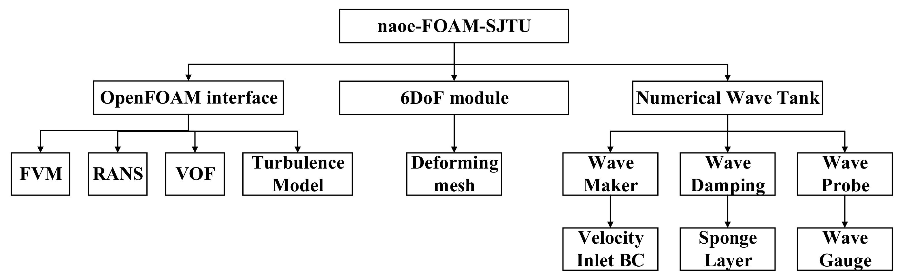
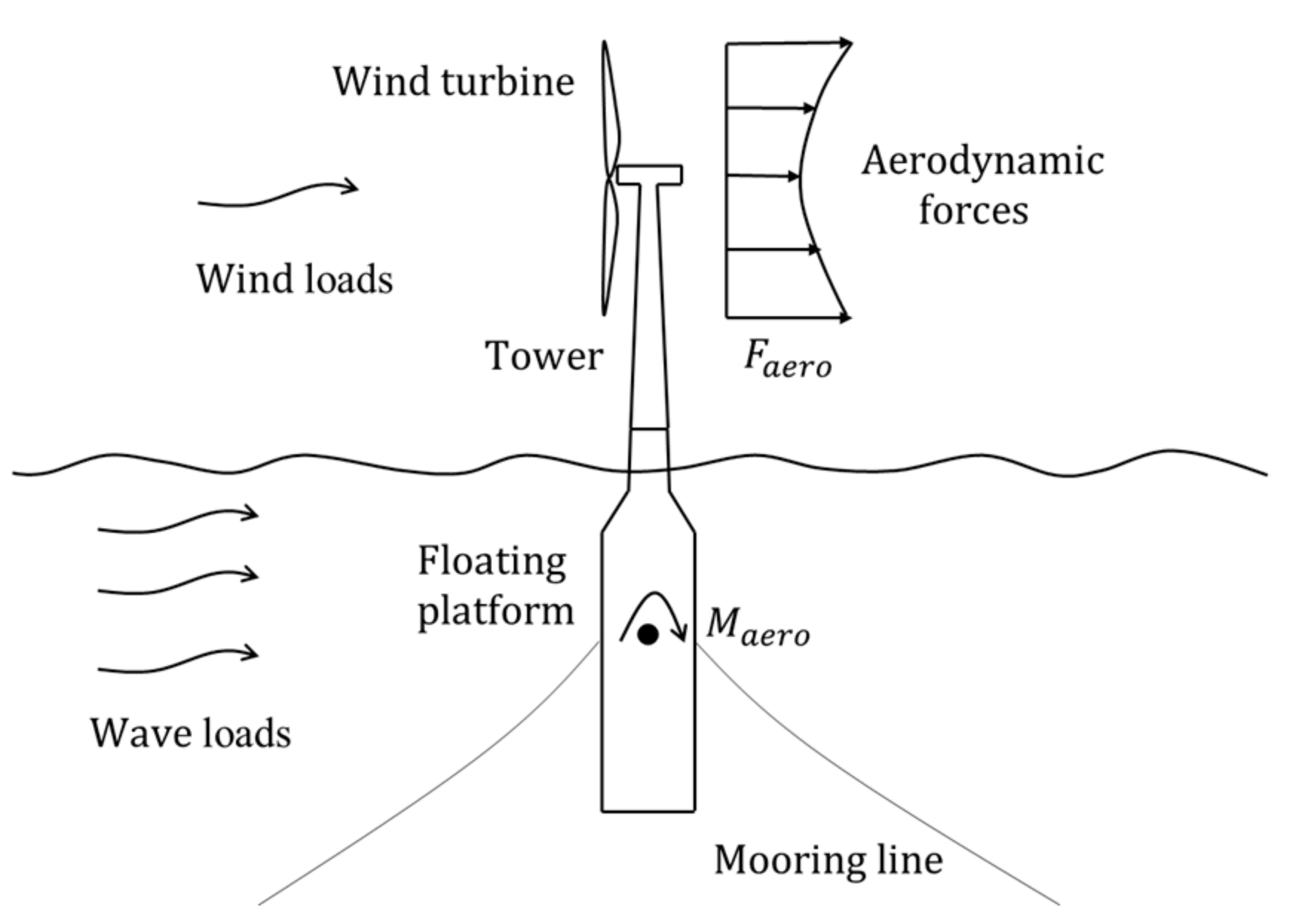
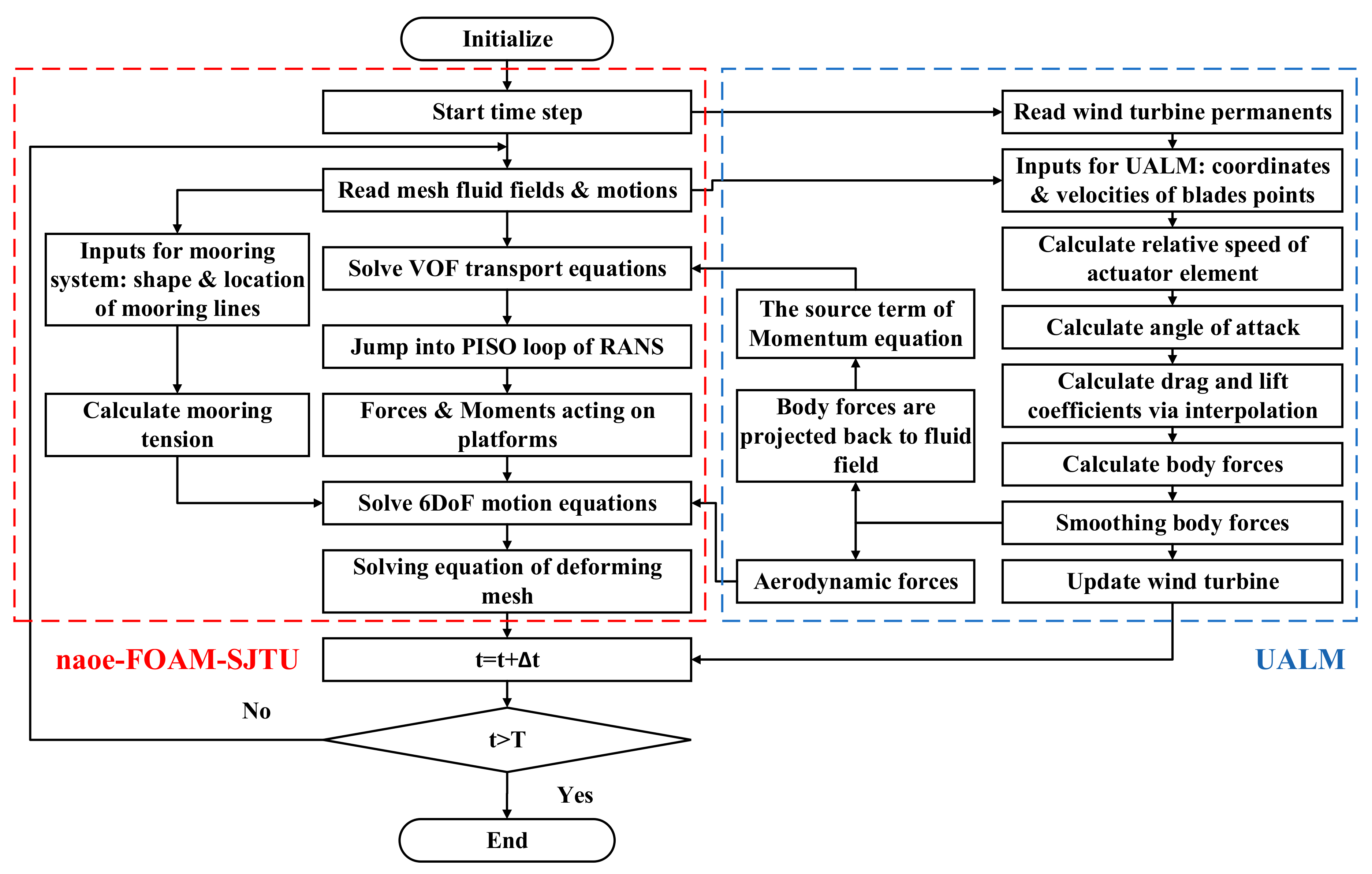
2.3. Coupled Aero-Hydrodynamic Modelling for FOWT

In the present work, three-dimensional Reynolds-averaged Navier-Stocks equations with k-ω SST turbulence model are applied to solve the transient, incompressible and viscous Newtonian fluid. Considering that the flow velocity of air phase is low, the air compressibility is neglected. The water and air are both regarded as incompressible fluids, which can be described by the same governing equations:
· U = 0
ρ U t + · ρ U U g U = p d g · x ρ + · μ e f f U + U · μ e f f + f σ + f s + f ε
where U represents the velocity field; U g donates the velocity of mesh points; ρ is the mixture density of water and air; p d is the dynamic pressure excluding the hydrostatic pressure; g is the gravity of acceleration vector; μ e f f = ρ ν + ν t is the effective dynamic viscosity, in which ν and ν t are kinematic viscosity and eddy viscosity, respectively; f σ is the surface tension term in two phases model and takes effect only on the liquid free surface; f s is a source term and takes effect only in the sponge layer in order to absorb the wave reflection; f ε represents the source term introduced from the modified ALM.
The FOWT-UALM-SJTU solver, which is composed of the modified ALM and in-house code naoe-FOAM-SJTU, is applied for full-scale CFD simulations of the FOWT system under combined wind-wave loads in the present work. The unsteady aerodynamic characteristics of the wind turbine are obtained by the UALM, and the hydrodynamic responses of the floating platform with mooring system are predicted by the naoe-FOAM-SJTU. As mentioned above, the interference effects between the wind turbine and the floating platform are taken into consideration in this coupled CFD analysis tool. Figure 5 shows the calculation procedure about how to predict the coupled aero-hydrodynamics performance of the FOWTs. It should be noted that a wake coupling approach is selected to achieve the interactions between the wind turbine and the floating platform. The additional velocity U M considered in the UALM module is induced by the 6DOF motions of the floating platform calculated from the last time-step. Then the smeared body forces are added into moment equations as the source term f ε and are introduced into the 6DOF motion equations to take the aerodynamic loads into account. In addition, the state of wind turbine such as the position of actuator point is also updated according to the motion responses at the last time-step.

3. Simulation Conditions
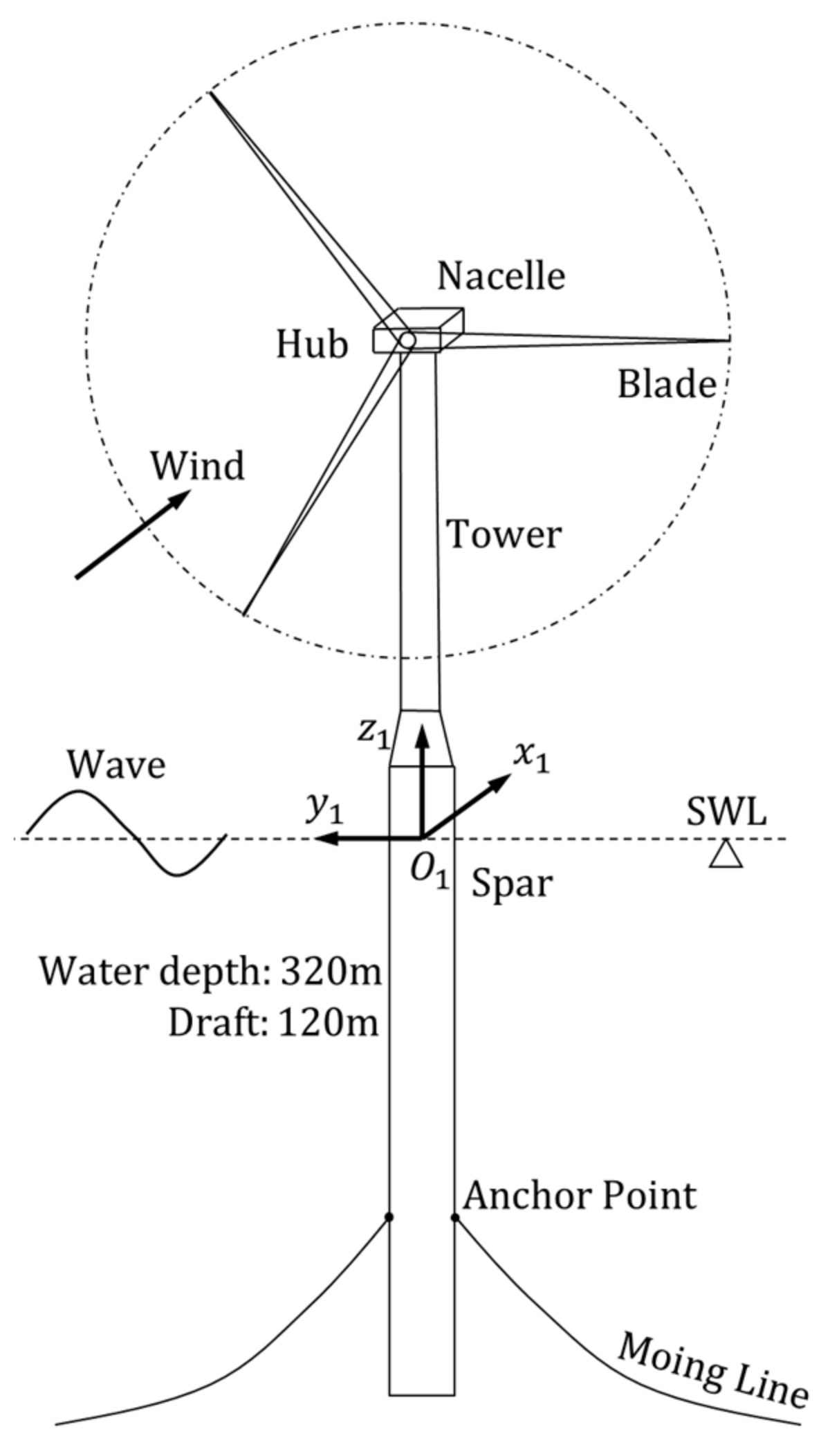
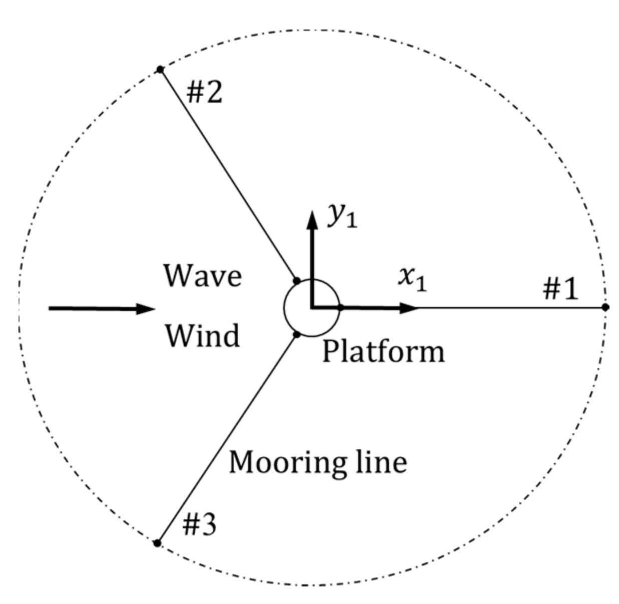
3.1. FOWT Model

A spar-type FOWT composed of the NREL 5-MW baseline wind turbine, the OC3-Hywind spar platform and a mooring system is chosen as the research object in the present work, and the schematic diagram of the FOWT system is shown in Figure 6. The NREL 5-MW baseline wind turbine is an upwind horizontal-axis wind turbine with three slender blades, which is a typical representative of the utility-scale sea-based turbines. The gross parameters of the wind turbine are summarized in Table 1, and detailed specifications can refer to Reference [51,52]. It should be noted that only the blades of the wind turbine are modelled and assumed as rigid structures in order to simply the simulations. Besides, the pre-cone angle and the shaft title of the wind turbine are both taken into consideration.
The spar-buoy concept platform OC3-Hywind is selected to support the NREL 5-MW wind turbine. To limit the motion responses of floating support platform and further decrease the impact on the wind turbine aerodynamics, the platform is moored by a mooring system with three catenary lines. As presented in Figure 7, the mooring lines are evenly arranged around the platform. It is noticeable that the hydrodynamic damping is not taken into consideration in the simulation of mooring system. Main parameters of the floating support platform and the mooring system are shown in Table 2 and Table 3. More detailed information can be found in Reference [25,53].

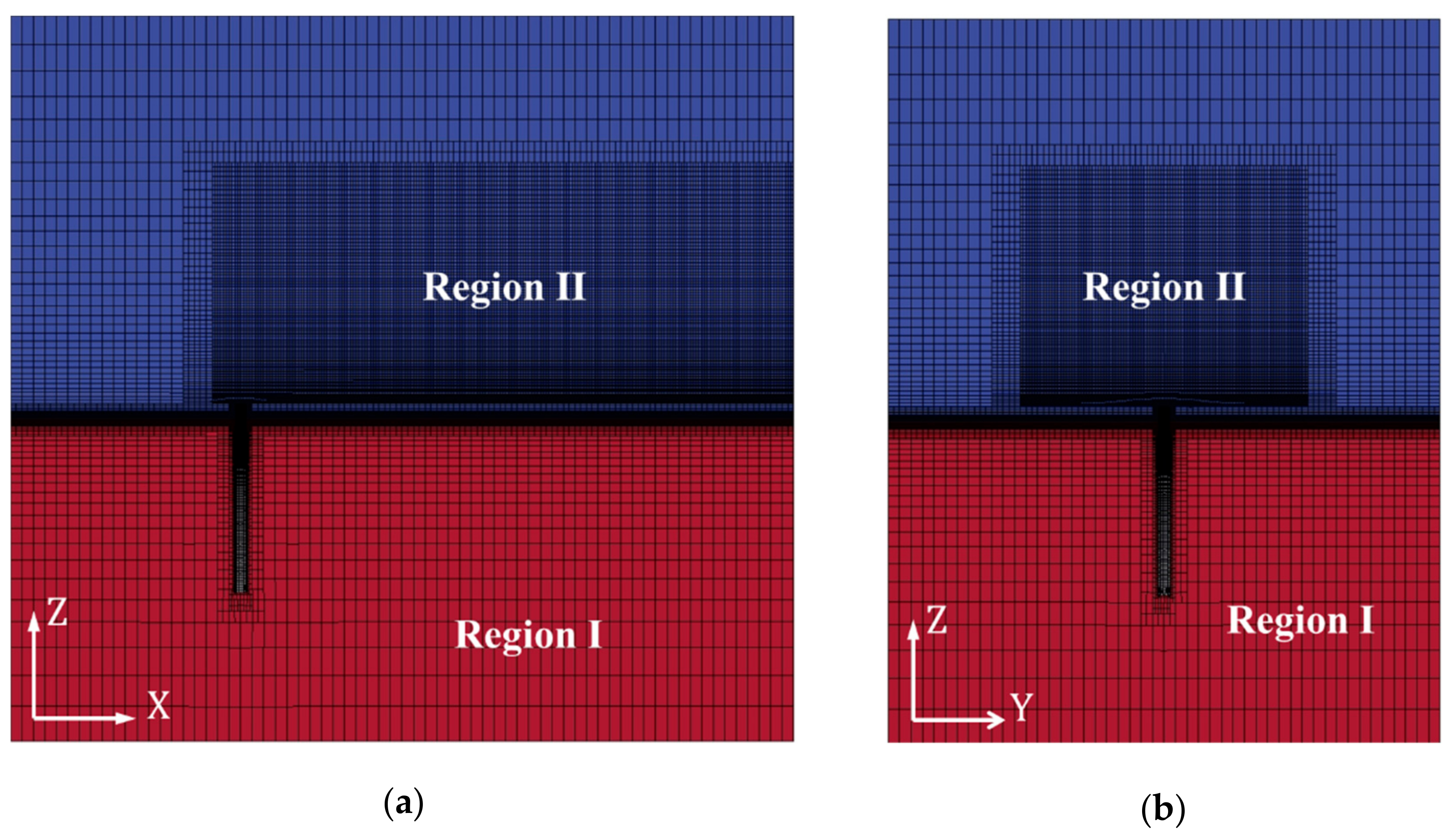
3.2. Computation Set Up

Although the rotor blades are simplified into virtual actuator line based on the modified ALM, the full-scale CFD simulations for the FOWT system by solving the RANS equations are still time-consuming. The main consideration for determining the size of computational domain is how to reduce the computation loads within acceptable calculation accuracy. A cuboid-shaped domain with the dimensions of 544 m (x) × 384 m (y) × 504 m (z) is created for coupled aero-hydrodynamic simulations of the spar-type FOWT system. Figure 8 shows the general arrangement of FOWT system in computational domain. The lengths in the negative and positive x-directions are 160 m (about one wave length λ   = 156 m) and 384 m (about three times of the rotor diameter D = 126 m), respectively. The depth of water phase in the negative z-direction is set to 224 m (70% of the real water depth d = 320 m) for the purpose of reducing computation. Considering the expansion of turbine wake, the air phase extends to 280 m (about 2.2D) along the positive z-direction. The rotor center of NREL 5-MW wind turbine is located at the height of H0 = 90 m. The OC3-Hywind spar is placed at the origin of earth-fixed coordinate system. The mooring line #1 is arranged to along the positive x-direction. In addition, a rectangular sponge layer with the length of 100 m located before the outlet boundary is adopt to absorb the wave reflection.
As shown in Figure 9, there are different mesh resolutions in the computational domain. For the background mesh, the grid sizes in x-direction and y-direction are both 8 m, while the sizes of background cell in negative and positive z-directions both linear change in order to limit the total grid number. The vertical size of background mesh (Region I) near water surface is 2 m, and it expands up to 20 m at top and bottom boundaries. Two refined mesh regions (Region II) are generated to capture the wake development behavior and the wave propagation. The grid size of refined mesh is only one fourth of the background mesh size. Besides, the grids near the spar platform are also refined. Thus, the total grid number of the computational domain is 3.5 million.
To achieve combined wind-wave incident condition, the uniform wind and 1st order Stokes wave is imposed at the inlet boundary for the air phase and water phase, respectively. The normal zero gradient condition is employed for the outlet boundary. Considering the bottom of computational domain is not the real water bottom, the free-slip condition is utilized in both the top and bottom boundaries. Besides, the symmetrical condition is applied to side planes of computational domain, and the platform surface is set to no-slip condition.
The wind and wave conditions in the present simulations refer to Jonkman and Musial [25]. The 1st order Stokes wave with a typical wave period of T = 10 s and a relative high wave height of H = 6 m is selected to be the incident wave. The rated wind speed of U 0 = 11.4 m/s is adopted. Considering the characteristic of height-dependent wind speed [54], exponential model [55,56] is applied to describe the wind shear phenomenon. The magnitude of the incident wind speed U z at the height of z is defined by the following equation:
U z = U 0 · z H 0 0 . 143
where H 0 = 90 m is the hub height of the wind turbine. The turbine rotor rotates at the rated angular velocity Ω   = 12.1 rpm in order to achieve the optimal tip speed ratio λ = 7. It needs to be reminded that the optimal control strategy of the FOWT is still under investigation. Therefore, neither the blade-pitch control nor the rotational speed control are considered in the present work. The blade-pitch angle is set to zero, and the rotor speed is kept at the rated value during the simulations. The wind and wave directions are both assumed to parallel to the positive-x direction, which is consistent with the direction of surge motion. As presented in our previous work [57], the sway and roll motions of the spar-type FOWT in a collinear wind-wave environment are small. Therefore, only the surge, heave, pitch and yaw motions are respectively considered in the present work, shown in Table 4.

4. Results and Discussions

In this section, coupled aero-hydrodynamic responses of the FOWT with various DOF platform motions (surge, heave, pitch and yaw) and different wind turbine states (parked and rotating) under combined wind-waved loads are compared and analyzed to study the interference effects between the unsteady aerodynamic characteristics and the platform motion responses.

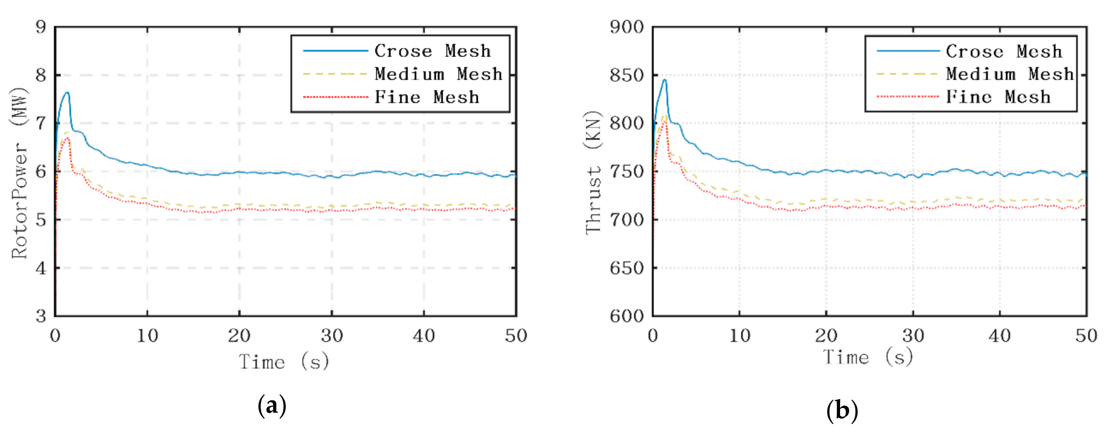
4.1. Grid Convergence Test

The convergence test of grid quality is firstly conducted to determine the appropriate grid size. Three sets of grids with different mesh resolutions are generated to perform coupled aero-hydrodynamic simulations for the FOWT with fixed platform. It is noted that both the 6DOF motions of floating platform and the rotation movement of wind turbine need to be taken into consideration for the determination of time-step size. Based on the previous experience [23], a time-step of Δ t = 0.01   s is suitable for the CFD simulations of the OC3-Hywind spar platform. The rotor blades rotate 0.726 degree at rated angular speed within this time step, which is much smaller than the reference value in the previous study about the NREL 5-MW wind turbine [26]. It indicates that this time-step size is small enough to meet the convergence requirement of aerodynamic loads calculation. Therefore, the same time-step size of 0.01 s is selected in the present work.
The aerodynamic loads including rotor power and thrust are compared for different gird densities, presented in Figure 10. It is shown that the aerodynamic loads have reached a steady state after about 20 s. The magnitudes of aerodynamic loads are nearly constants, for the impacts of platform motions are not taken into account. The mean values of rotor power and thrust averaged from 40 s to 50 s are listed in Table 5, which are presented in percentage difference over the data from the fine mesh. Comparison results show that the difference for aerodynamic loads between different mesh resolutions significantly decreases with the increase of grid density. The difference for the rotor power between the medium mesh and fine mesh is below 1.3%, and it decreases to 0.4% for the thrust, indicating that the results are insensitive to the grid number. Thus, the medium mesh is selected for the later coupled aero-hydrodynamic simulations to reduce calculation time with acceptable computation accuracy.

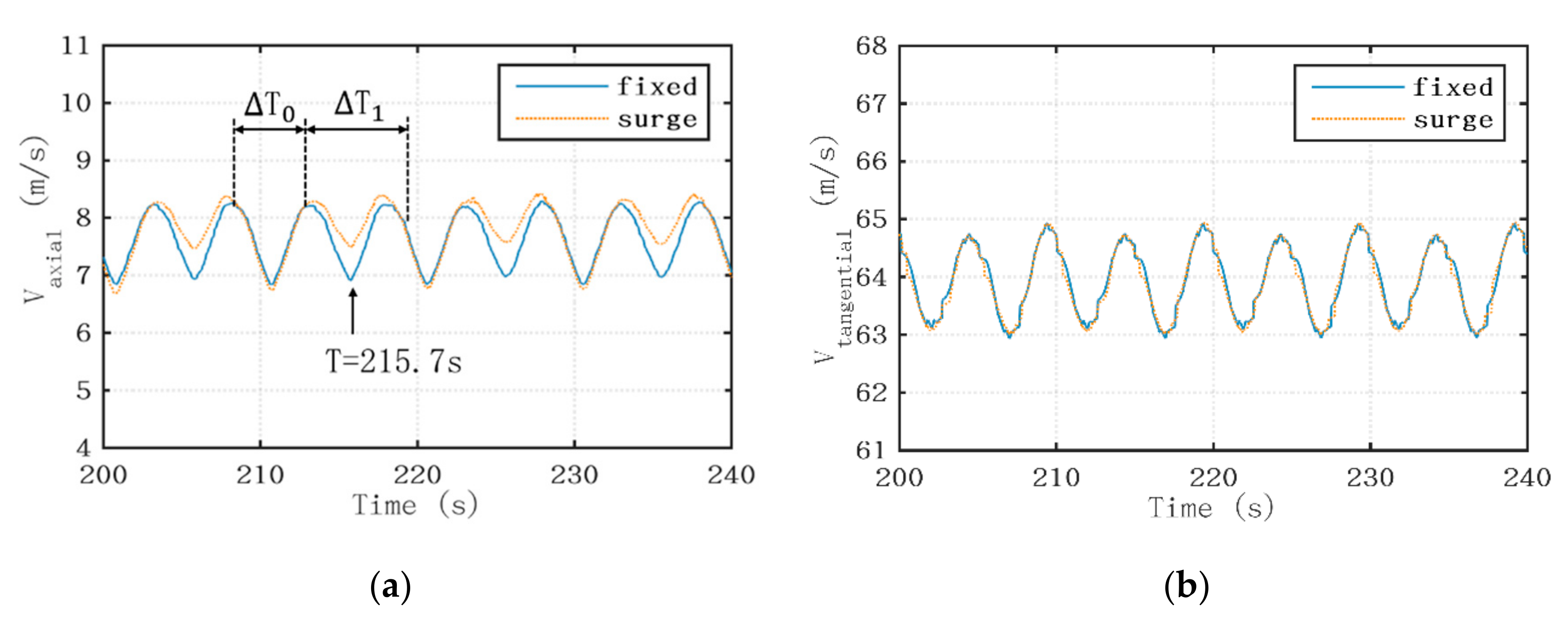
4.2. Additional Velocity Induced by the Platform Motions

The platform motions have impacts on the aerodynamic loads in two aspects. On one hand, the magnitude of local relative wind speed experienced by the rotating blades varies with additional velocity vector induced by the platform motions. On the other hand, the velocity components of local relative wind speed in the blade-aligned coordinate system also change with the position of floating platform, leading to the variation of local attack angle. Both the change of local relative wind speed and local attack angle will cause the variation of lift and drag forces acting on the rotor blades and eventually change the aerodynamic performance [8].
As presented in Figure 11, the additional velocity U M can be divided into several velocity components induced by different DOF platform motions. U S and U H represent the additional velocities induced by surge motion and heave motion, respectively. U P and U Y donate the velocity components induced by pitch motion and yaw motion, respectively.
U M = U S + U H + U P + U Y
U S = u s u r g e
U H = u h e a v e
U P = ω P · x i x c
U Y = ω Y · x i x c
where u s u r g e and u h e a v e represent the surge velocity and heave velocity, respectively. ω P and ω Y are pitch angular velocity and yaw angular velocity, respectively. Then the velocity competent of these additional velocities in direction 0 ( x 2 ) can be expressed as:
U M , 0 = U S , 0 + U H , 0 + U P , 0 + U Y , 0
U S , 0 = U S · cos α P β
U H , 0 = U H · sin α P β
U P , 0 = U P · cos α P β γ
U Y , 0 = U Y · cos α P β
where α P is the pre-cone angle. β represents the angle caused by the shaft tilt. γ is determined by the relative position between the ith actuator point x i and the rotating center x c , which varies periodically due to the rotation of rotor blades. It is noted the magnitude of U M , 0 cannot be neglected compared with incoming wind speed component U in , 0 . According to Equation (5) and Equation (7), U M , 0 plays an important role in the calculation of local attack angle and local relative wind speed. However, the projection of U M in direction 1 ( y 2 ) is much smaller than the tangential velocity Ω r . Thus, it shows minor effects on the local attack angle and the local relative wind speed.
Moreover, the velocity components of incoming wind speed U in in blade-aligned coordinate system also change with the position of rotating blades. U in , 0 and U in , 1 represent the velocity components of incoming wind speed in direction 0 ( x 2 ) and direction 1 ( y 2 ) respectively, which are defined by the following equation:
U in , 0 = | U in | · cos < U in , x 2 >
U in , 1 = | U in | · cos < U in , y 2 >
The vector angles between U in and direction vectors x 2 , y 2 ), are significantly affected by pitch motion and yaw motion. As shown in Figure 11, θ P and θ Y are platform pitch angle and platform yaw angle, respectively, which can be obtained by the integration of angular velocity with time.
θ P = 0 t ω P d t
θ Y = 0 t ω Y d t
Above all, the velocity components at the blade section are significantly altered by the motion responses of the floating platform, leading to the variation of local relative wind speed and local attack angle. These changes finally result in the highly unsteady aerodynamic characteristics of the FOWT system.

4.3. Unsteady Aerodynamic Performance Under Specific Platform Motion

As introduced above, the platform motions alter the aerodynamic performance of FOWT by affecting local relative wind speed and local attack angle. A typical blade section of blade #1 at 0.8r (r is the blade radius) from the blade root is selected herein to explore the impacts of different DOF platform motions on the aerodynamic characteristics of wind turbine.
Figure 12a shows the comparison of time-dependent axial speed ( U 0 ) experienced by the selected blade section for fixed case and surge case. The axial speeds in two cases both periodically vary with time, while the variation periods are different. It is found that the instantaneous axial speed in fixed case varies with the same period of the rotation of turbine blades, about 5 s, which is almost half of the incident wave period. Two factors that high-dependent wind speed and the structure characteristic of wind turbine both result in this periodical change of the axial speed in fixed case, which are ignored in the previous coupled dynamic analyses of the FOWT [11,12,13,26,27]. As presented in Equation (13), the exponential model is used to define the incoming wind speed. The magnitude of the wind speed along the height is plotted in Figure 13. Obviously, the incoming wind speed is related to vertical position of rotating blades. Due to the large diameter of NREL 5-MW wind turbine, the magnitude of incoming wind speed at the selected blade section varies from 10.1 m/s to 12.1 m/s during the rotational motion of blades. Furthermore, the velocity component of the incoming wind speed in direction 0 ( U in , 0 ) also varies with the same frequency as the rotational motion because of the pro-cone angle and the shaft tilt. The axial speeds of the selected blade section are compared for uniform wind condition and shear wind condition to explore the impacts of the pro-cone angle and the shaft-tilt of wind turbine, shown in Figure 15. The fluctuating range of axial speed under uniform wind condition is about 0.3 m/s, much smaller than that under shear wind condition. It indicates that the axial speed experienced by the rotating blade is more greatly affected by the height-dependent incoming wind speed.
The platform surge responses including the displacement and velocity in surge case are illustrated in Figure 14. Affected by the platform surge motion, the variation period of the axial speed at the selected blade section is almost equal to the incident wave period of 10 s. As mentioned above, the additional velocity induced by platform motion also contributes to this periodical change of axial speed. Therefore, the axial speed in surge case is dependent on both the height-dependent incoming wind speed and the surge velocity. When the platform surge velocity is greater than zero (T0 = 208.5 s~212.7 s), the platform surge motion direction is consistent with the direction of the incoming wind speed [13]. Thus, the axial speed experienced by the rotating blades in fixed case is smaller than that in fixed case. Conversely, the axial speed become larger when the platform surge velocity is less than zero (T1 = 212.7 s~218.5 s). It is noted that axial speed in surge case is about 0.6 m/s larger than that in fixed case when the incoming wind speed and surge velocity both reach to the valley values (T = 215.7 s), suggesting that the influence of surge velocity on axial speed is considerable. The tangential speeds ( U 1 ) at the selected blade section are also compared between the fixed case and surge case, as shown in Figure 12b. There are minor differences between the tangential speeds in fixed case and surge case. Moreover, the tangential speeds under uniform wind condition and shear wind condition are presented in Figure 15b. It appears that the periodical variation of tangential speed in surge case is mainly caused by the pro-cone angle and the shaft tilt instead of the height-dependent incoming wind speed. As shown in Figure 16a,b, the platform surge motion has little influence on the local relative wind speed experienced by the rotating blade. However, the local attack angle is obviously affected by the additional velocity induced by the platform surge responses. It is seen that the local attack angle and axial speed have the same variation trend and period. Therefore, it is the local attack angle instead of the local relative wind speed is dominantly influenced by the surge motion, and a similar conclusion can be found in Wen et al. [8]. The change of local attack angle eventually leads to the variation of aerodynamic forces acting on rotor blades with a result of fluctuating rotor power and thrust. Figure 17a,b present the aerodynamic loads obtained by integrating the body forces along spanwise direction. It is shown that the aerodynamic loads in fixed case are almost unchanged over time, while the aerodynamic loads including rotor power and thrust in surge case vary periodically with different fluctuating ranges. The variation ranges of the rotor power and the thrust in surge case are 15% and 8% of the average values, respectively.
To illustrate the influence of platform pitch responses under combined wind-wave loads on the unsteady aerodynamic characteristics, the axial speed and tangential speed at the blade section are presented in Figure 18a,b. According to Equations (24) and (25), the velocity components of incoming wind speed in blade-aligned coordinated system are significantly affected by the platform pitch angle. The additional speed induced by platform pitch angular velocity also alters the axial speed and tangential speed. Moreover, the height-dependent incoming wind speed shows considerable effects on the axial speed from the above analysis. Therefore, the variation of the relative wind speed is the result of the comprehensive efforts of height-dependent incoming wind, platform pitch angle and pitch angular velocity. It is shown in Figure 18a that the axial speed in pitch case gradually increases to the peak value during T2 (210.6 s~213.8 s). In this period, the incoming wind speed firstly varies from the minimum to the maximum and then decreases. The pitch angular velocity shown in Figure 19 changes from the positive to the negative, contributing to the increase of the axial speed. However, the axial speed and incoming wind speed both decrease to valley value at the same time (T = 215.8 s), indicating the additional velocity induced by platform pitch motion has limited influence on the axial speed experienced by the rotating blade. Then the axial speed increases to the peak value again (T = 217.0 s) with the increase of the incoming wind speed. It is obviously seen that the peak value of axial speed at T = 217.0 s is much smaller than that at T = 213.8 s, resulting from the comparative small platform pitch angle and pitch angular velocity. The axial speed reduces to the valley value when the incoming wind speed decreases to the minimum during T3 (217.0 s~220.6 s). Due to the increased platform pitch angle and pitch angular velocity, the minimum value of the axial speed at T = 220.6 s is much smaller compared with that at T = 215.8 s. It can be concluded that the large platform pitch angle amplifies the variation range of the axial speed. The axial speed in pitch case is dominated by the platform pitch angle instead of additional velocity induced by platform pitch angular velocity. As shown in Figure 18b, the tangential speed varies with the same frequency as rotational motion of the blade. The variation of platform pitch angle alters the direction of tangential speed and further amplifies the fluctuating range of tangential speed. It is noted that there exists a difference between two adjacent valley values, marked out by Δ V t . This means that the additional velocity induced by platform pitch motion also has small effects on the tangential velocity.
Due to the fact that the magnitude of tangential speed is much larger than that of axial speed, the local attack angle has the same variation trend of the axial speed according to Equations (4) and (5), as shown in Figure 20a. In addition, the profile of local relative wind speed experienced by rotating blades presented in Figure 20b is similar to that of tangential velocity, which can also be concluded from Equation (7). Both the local relative wind speed and the local attack angle fluctuate significantly due to the platform pitch responses [9], resulting in the periodical variation of aerodynamic loads shown in Figure 21a,b. The fluctuating ranges of rotor power and thrust in pitch case are almost as large as those in coupled case.
Comparisons for the local relative wind speed and the local attack angle at the blade section in fixed case, heave case and yaw case are achieved in Figure 22. It appears that both platform heave motion and platform yaw motion under the given wind-wave condition have marginal effects on the aerodynamic characteristics. The aerodynamic loads in heave case and yaw case also show little discrepancy with those in fixed case, presented in Figure 23. Although the magnitude and the direction of local relative wind speed experienced by the rotating blades both significantly vary with the platform yaw angle, the platform yaw responses in the present collinear wind-wave condition are too small to have considerable effects on the aerodynamic performance. As Figure 24 shows, the average yaw angle is only about 1 degree. Besides, the platform heave responses with time have been presented in Figure 25. As the direction of heave motion almost parallels to the rotor plane, the influence of platform heave responses on the aerodynamic characteristics including local relative wind speed and local attack angle can nearly be neglected.
The aerodynamic loads obtained from different simulation cases are summarized in Table 6 and plotted with bar chart in Figure 26. The mean values of rotor power under different DOF platform motions are all close to the average power output under fixed platform, and the similar condition also occurs for the average thrust. Platform motions in the present wind-wave condition show minor impacts on the average aerodynamic loads. It is interesting to find that the mean aerodynamic loads of the spar-type FOWT with platform pitching motion are lower (about 5%) than those in fixed condition, which is different from the conclusion that the mean power output increases when the wind turbine experiences pitching motion in Wen et al. [9]. This is mainly caused by different average platform pitch angles. In the present simulation, interference effects between aerodynamic loads and platform motion are considered, resulting a larger average platform pitch angle, while it is set to zero in Wen et al. [9]. The fluctuating amplitudes of the aerodynamic loads under different DOF platform motions change greatly, shown in Table 6. The rotor power under platform pitch motion varies from 3.31 MW to 6.96 MW, about 72% of the mean value, which is quite close to variation range of power output in coupled case. The fluctuating range of the rotor power under platform surge motion is 0.85 MW and nearly 15% of the average value, much smaller than that in coupled case. Moreover, the variation ranges of the thrust under different conditions are smaller than that in coupled case. The thrust experiencing platform pitch motion has a variation range of 240 kN, about 34% of the mean value. This percentage decreases to 7% in platform surging condition. It appears that the rotor power is much more sensitive to the platform motion responses compared with the thrust. Obviously, the fluctuating ranges of the aerodynamic loads under 6DOF platform motions are not a simple summation of those under single DOF platform motion. The effects of different DOF motions on the aerodynamic loads are coupled, and the relationship between the platform motions and the aerodynamic loads is rather complex and nonlinear. Platform pitch responses including pitch angle and pitch angular velocity show the most significant impacts on the variation ranges of aerodynamic loads, and the surge velocity also has considerable effects on the fluctuating amplitudes of rotor power and thrust. Besides, the yaw motion and heave motion in the given wind-wave condition are both found to have little effects on aerodynamic loads when the incoming wind speed is parallel to the rotating axis of the wind turbine.

4.4. Platform Motion Responses Under Combined Wind-Wave Loads

The hydrodynamic responses of the OC3-Hywind spar platform under wind and wave loads have been investigated in our previous work [23], and the average platform motions are found to be dominated by the aerodynamic loads. Herein, the motion responses of the floating support platform under combined wind-wave loads are discussed to further understand the impacts of aerodynamic forces on the hydrodynamic performance of the spar-type FOWT. The dynamic motion responses in different cases are also compared and analyzed to explore the coupling phenomena between different DOF platform motions.
Time history curves of platform surge motion with different wind turbine states and platform motion modes are presented in Figure 27a. The platform surge responses, which are composed of a significant long-drift motion and a minor wave-frequency motion, have the same movement tendency in different cases. It is noted that the maximum value and mean value of the platform surge displacement in surge case are both larger than those in coupled case, resulting from the bigger axial force Fx. As analyzed above, the average aerodynamic loads in coupled case are smaller because of the platform pitch responses. This leads to the decrease of axial force Fx acting on the floating platform, shown in Figure 28a. In addition, the significant long-drift motion in different cases is mainly induced by the aerodynamic thrust, while the small wave-frequency motion is caused by the periodically varying hydrodynamic loads.
The comparison of platform pitch responses in fixed case, pitch case and coupled case is shown in Figure 27b. The fluctuating ranges of the platform pitch angle in different cases show a minor difference within 0.2 degree. However, the discrepancy between the average platform pitch angles in different cases is considerable. The mean values of platform pitch angle in coupled case and pitch case are 4.1 degree and 4.3 degree, respectively, while it decreases to about zero degree in parked case. According to the previous study [28], the fluctuating amplitudes of platform motions depend on the hydrodynamic loads, while the average values of motion responses are dominated by the aerodynamic loads. The pitching moment components presented in Figure 28b fully illustrates this conclusion. The pitching moment induced by the wave loads has a larger variation amplitude and a smaller mean value compared with that caused by the wind loads. It is interesting to find that the mean value of platform pitch angle in pitch case is about 0.2 degree larger than that in coupled case, and the similar condition also occurs for the platform surge displacement. It indicates that the motion responses in coupled case may decrease due to the coupling between different DOF platform motions. This coupling effect is enhanced in the FOWT system due to aerodynamic forces.
Significant discrepancies in the platform heave motion among fixed case, heave case and coupled case can be seen in Figure 27c. Due to the platform pitch motion in coupled case, the rotor plane is not exactly vertical to sea level all the time. Therefore, the aerodynamic thrust has a component along z axis, as Figure 28c shows. This vertical force periodically varies with time and makes the mean draft of floating platform in coupled case greater than that in parked case. Thus, the mean value of heave motion is about 0.16 m less than that in parked case. Furthermore, the hydrodynamic forces change with the draft of the floating platform, leading to the larger fluctuating range of the heave displacement. The fluctuating amplitudes of platform heave displacements in coupled case and parked case are 1.57 m and 0.67 m, respectively, indicating a 43% difference between them. Although the pitch motion is not considered in heave case, the aerodynamic thrust also have a minor competent along vertical direction due to the shaft tilt of the wind turbine. Therefore, the mean value of platform heave displacement in heave case is somewhat smaller compared with that in parked case. It can be concluded that the heave responses of FOWT system are significant affected by the coupling between the heave motion and the pitch motion.
It is noted that the incoming wind speed in the present simulations is along the x axis, which is nearly vertical to the rotor plane. The aerodynamic forces distributed on the rotor plane are uniform and are almost symmetrical to the xz plane. Thus, the yawing moment caused by the aerodynamic forces is small, as shown in Figure 28d. Moreover, this moment induced by the hydrodynamic loads is also comparatively small because of the circular waterplane of the OC3-Hywind spar platform. Therefore, the time-dependent platform yaw angles in park case, yaw case and coupled case all have minor mean value and fluctuating range. Figure 27d shows the platform yaw angles in different conditions, which are all in the range of −0.2~1.4 degree. It can be found that the mean platform yaw angle increases with the yawing moment, while the yawing moments resulting from the aerodynamic forces and hydrodynamic forces are both relatively small in current collinear wind-wave condition.

4.5. Interactions Between the Platform Motion and the Rotating Blades in Wake Field

To further investigate the interactions between the platform motions and the rotating blades, the wake field characteristics including the instantaneous flow velocity and vorticity in the near wake region are extracted from the simulation results and analyzed in detail. Figure 29 shows the instantaneous flow velocity in different simulation cases. The wind velocity curves in horizontal plane at the hub height z = 90 m and vertical plane at y = 0 m are both illustrated. As seen in the Figure 29a, the magnitude of wind velocity sharply decreases when the incoming wind passes through the rotor plane. It is noted that the velocity deficit in the near wake region behind the wind turbine is not fully symmetrical to the xz plane in all simulation cases. This means that aerodynamic loads distributed on the rotor plane are asymmetrical, which contributes to the yawing moment acting on the FOWT. Moreover, the loss of velocity in near wake region in pitch case and coupled case is found to be obviously greater than that in other cases, indicating that the platform pitch motion leads to more serious velocity deficit phenomenon [26]. Other platform motions, such as surge motion, heave motion and yaw motion, all have little impacts on the velocity in the near wake field. In addition, the wake deflection is clearly observed in the near wake region in pitch case and coupled case, while this phenomenon is not captured in other cases. It appears that the platform pitch motion may accelerate the wake deflection progress and make it occurs in the near wake region. The distribution of wake flow velocity at the central vertical plane shown in Figure 29b also proves this point. It is seen that the wake obviously moves up in pitch case and coupled case.
The instantaneous vorticity in the hub height horizontal plane and the central vertical plane is presented in Figure 30. The tip and root vorticities behind the rotating blades can be clearly observed, as shown in Figure 30a. By comparing the development of wake behavior in the hub height horizontal plane under different DOF platform motions, the width of turbine wake is found to become larger when the platform pitch motion is considered. This width also increases with the increasing distance from the wind turbine, which means that the downstream FOWTs may be influenced by the wake flow. Moreover, the platform pitch motion is found to be the most significant factor that leads to misdistribution of wake field, which further deteriorates the inflow condition for the downstream FOWTs and increase the instability of flow field [26]. Figure 30b shows the instantaneous vorticities distribution in the central plane. The tip vortices generated from the rotating blades move about four times of the distance between the adjacent vortex rings along the flow direction before they are merged in the wake field. Due to the periodical platform pitch motion, the direction of vortex shedding varies with the platform pitch angle, resulting the increased wake width and turbulence intensity. Other single DOF platform motions including the surge, heave and yaw all have little impacts on the wake flow.

5. Conclusions

In this study, the coupled aero-hydrodynamic performance of a spar-type FOWT composed of the NREL 5-MW wind turbine and the OC3-Hywind spar platform is investigated by the validated CFD analysis tool FOWT-UALM-SJTU. The coupled dynamic responses of the FOWT with various DOF platform motions (surge, heave, pitch and yaw) and different wind turbine states (parked and rotating) are analyzed to explore the interference effects between the wind turbine and the floating platform. The dynamic responses of local relative wind speed and local attack angle at the blade section and wind-wave loads acting on the platform are discussed in detail to reveal the interaction mechanism between the aerodynamic loads and different DOF platform motions. Several conclusions for the spar-type FOWT can be drawn from the simulation results and analyses.
(1)
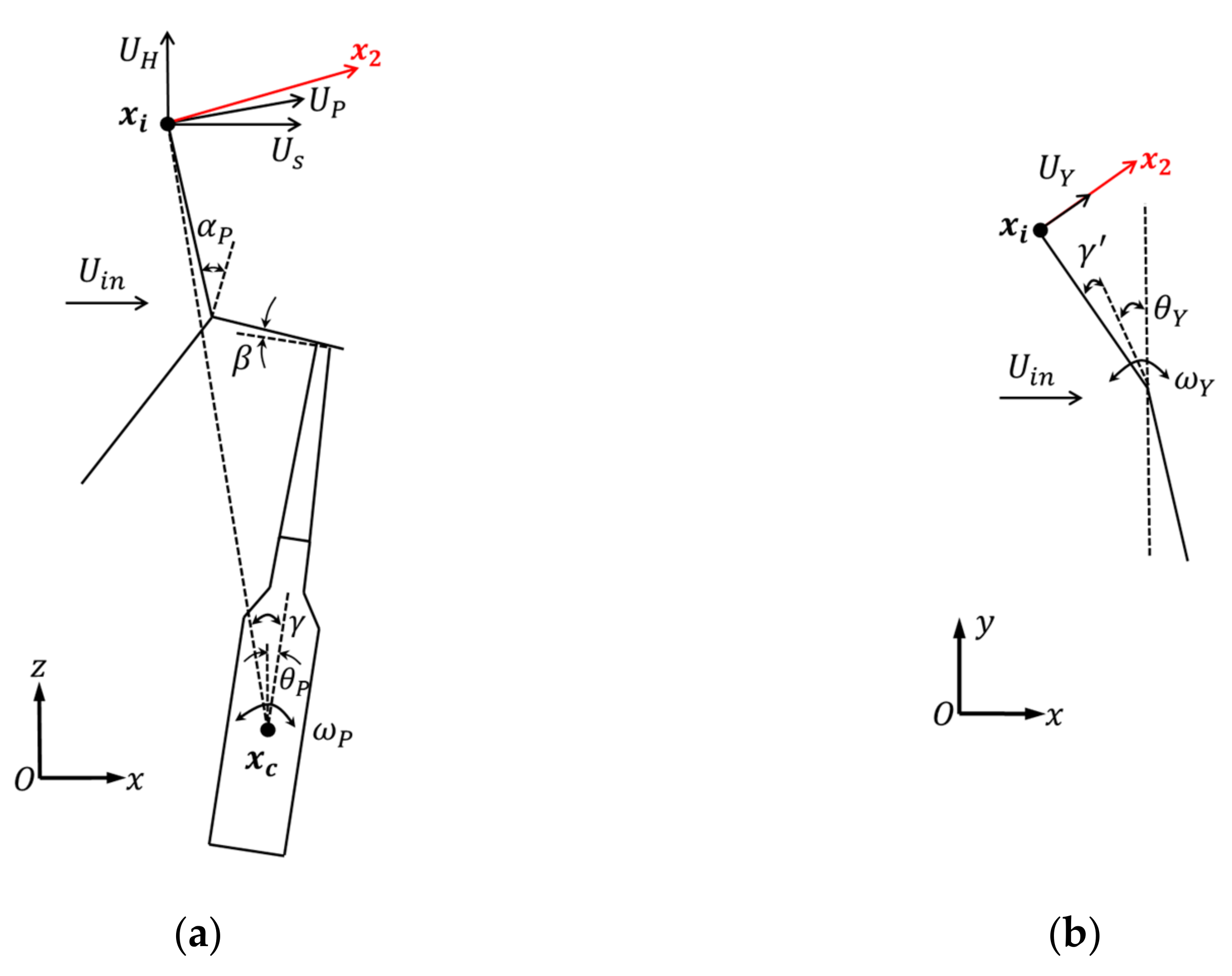
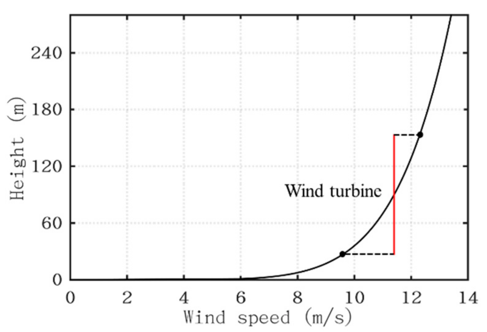
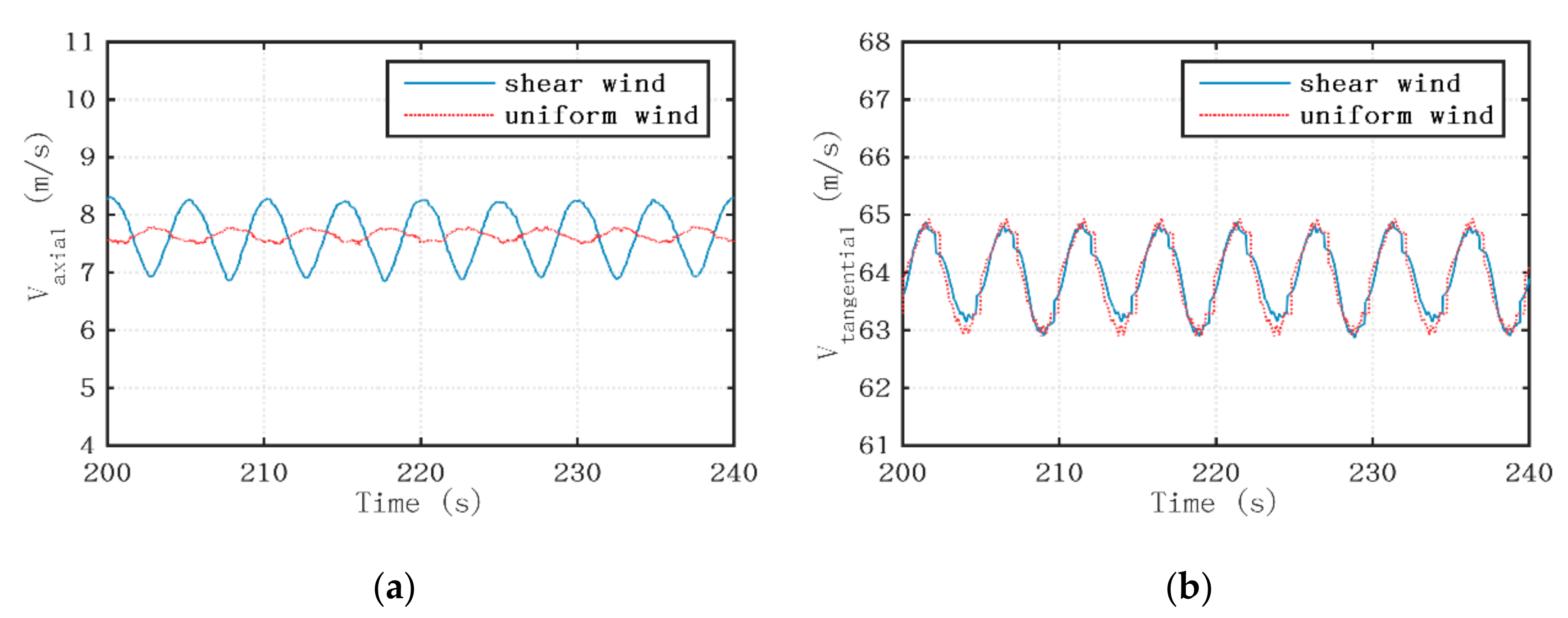
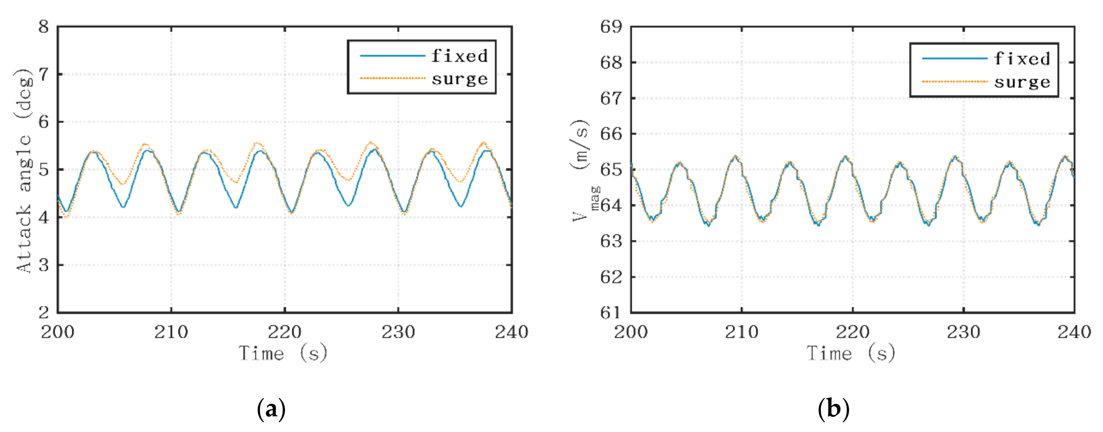
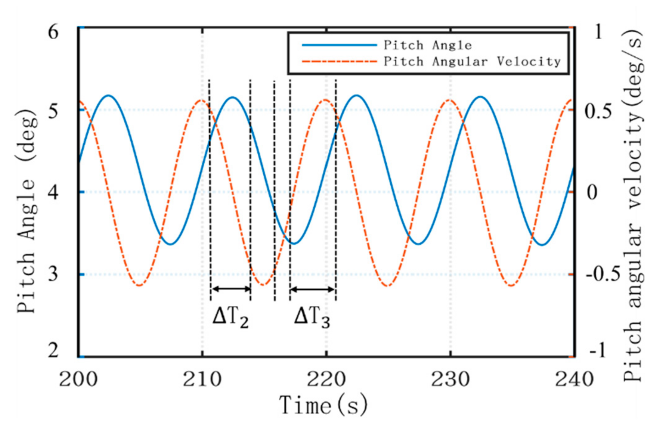
Both the platform pitch angular velocity and the platform pitch angle have considerable effects on the local relative wind speed and the local attack angle experienced by the rotating blades. The platform surge velocity significantly alters the local attack angle instead of the local relative wind speed. Besides, the height-dependent wind speed, the shaft-title and the pro-cone angle of wind turbine all contribute to the variation of the local attack angle.
(2)
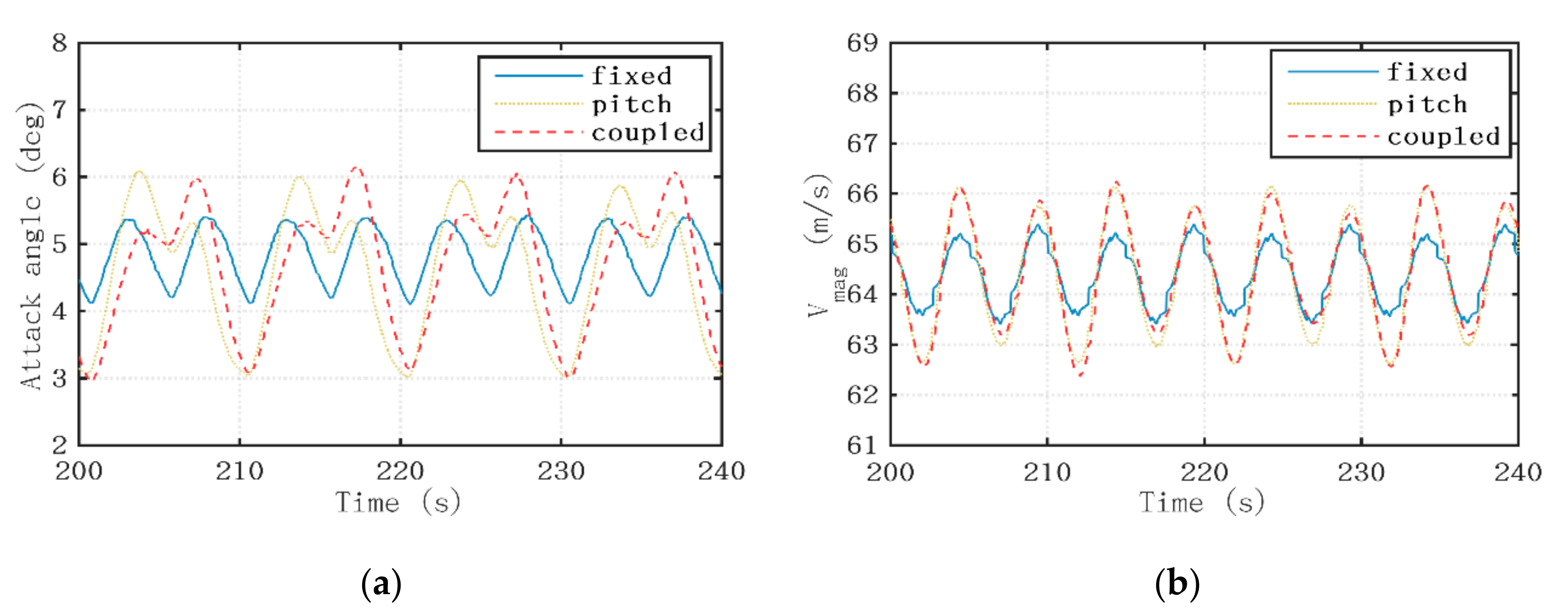
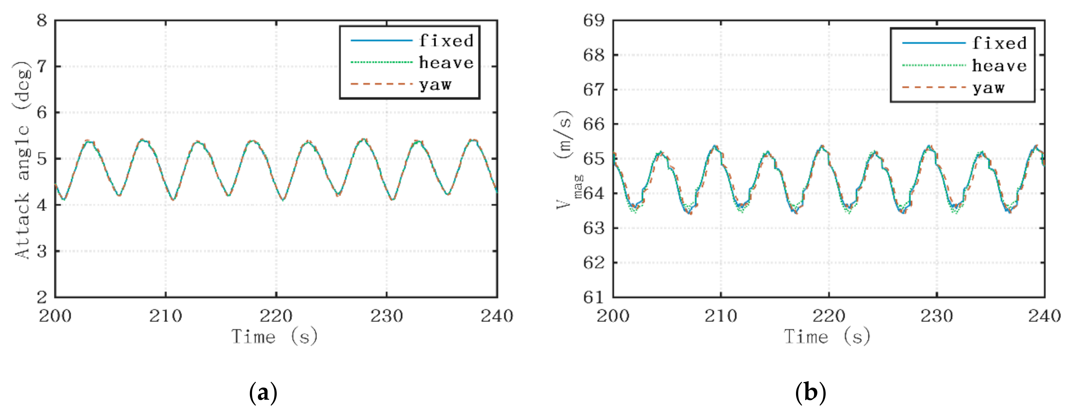
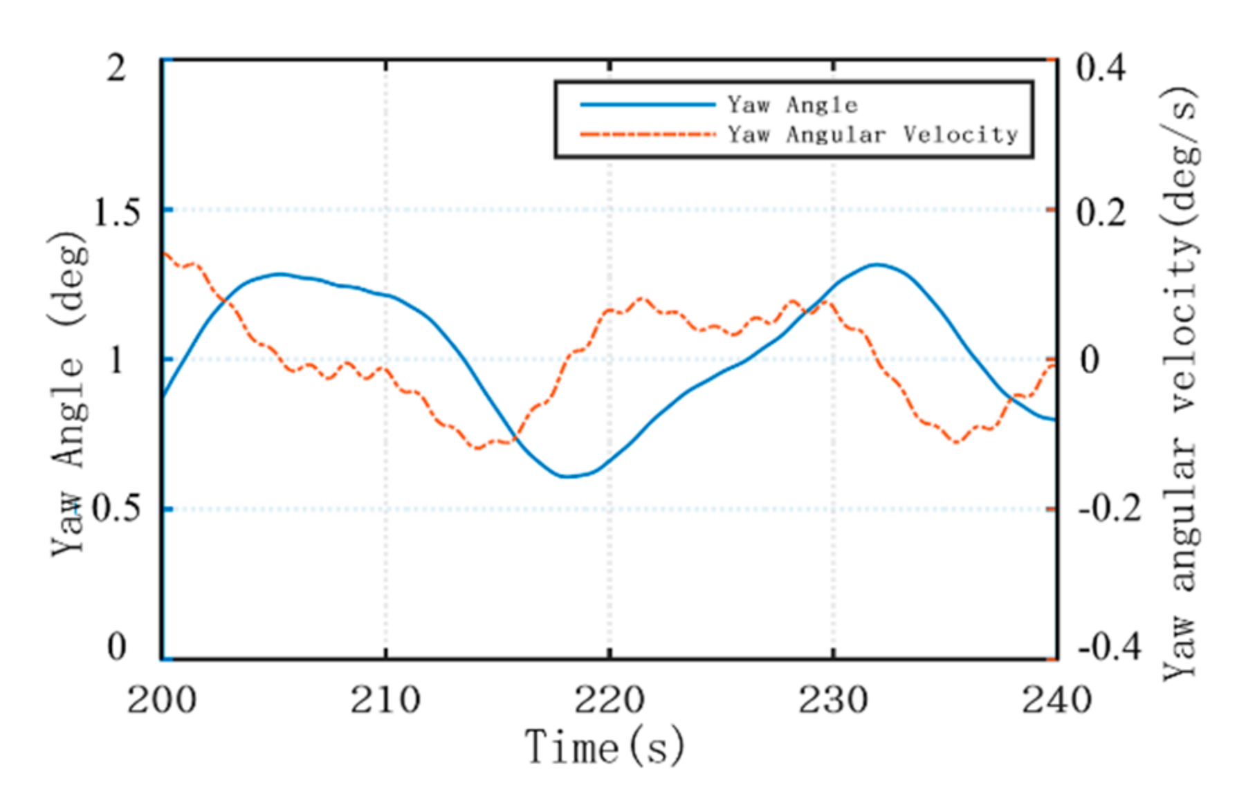
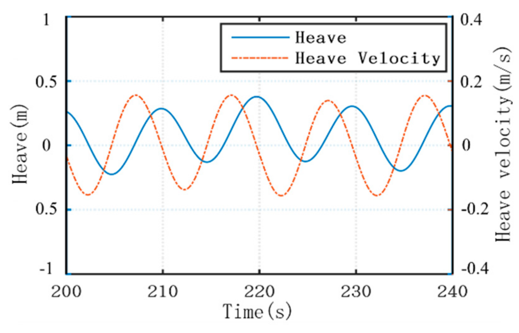
The fluctuating range of the aerodynamic loads with platform pitching motion is almost five times that with platform surging motion under the same operating wind-wave condition. The platform yaw motion in collinear wind-wave environment is too small to have significant effects on the aerodynamic loads, and the influence of the platform heave motion can nearly be neglected.
(3)
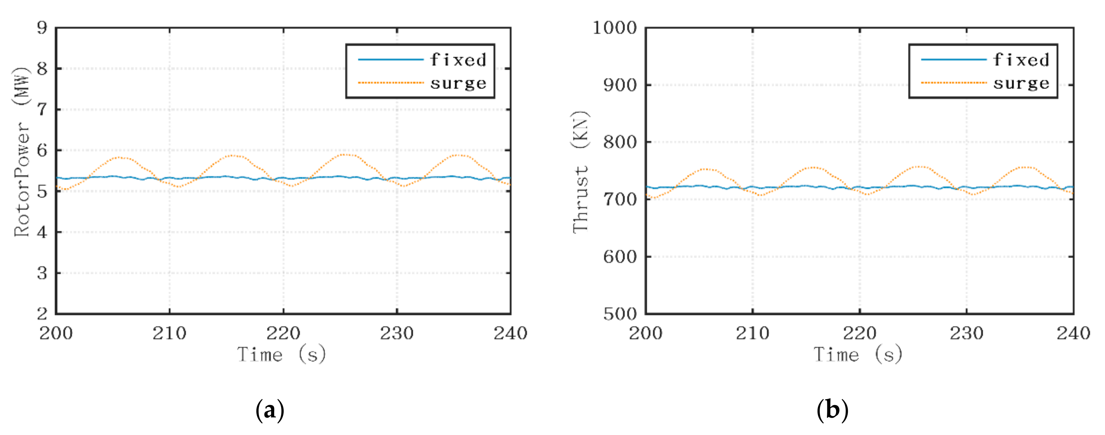
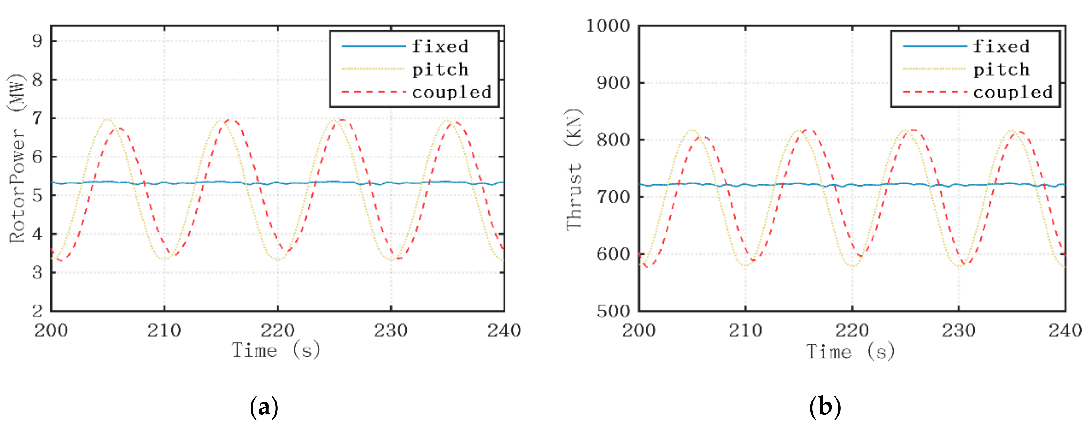
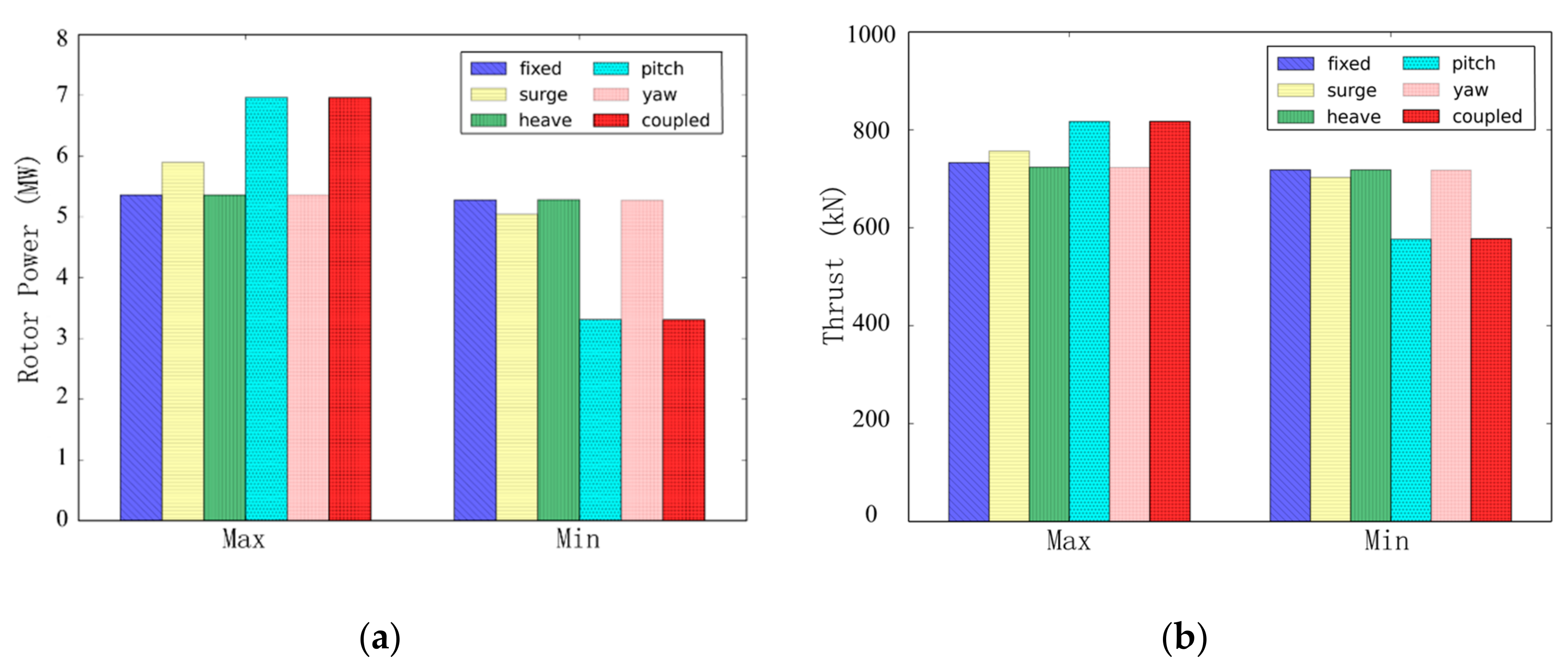
Compared with the thrust, the rotor power is shown to be much more sensitive to the platform motions. The percentage of the variation amplitude with respect to the mean value of the rotor power is about two times that of the thrust. Moreover, the mean power output is reduced due to the large platform pitch angle when the shaft-tilt and the prone-cone angle are considered.
(4)
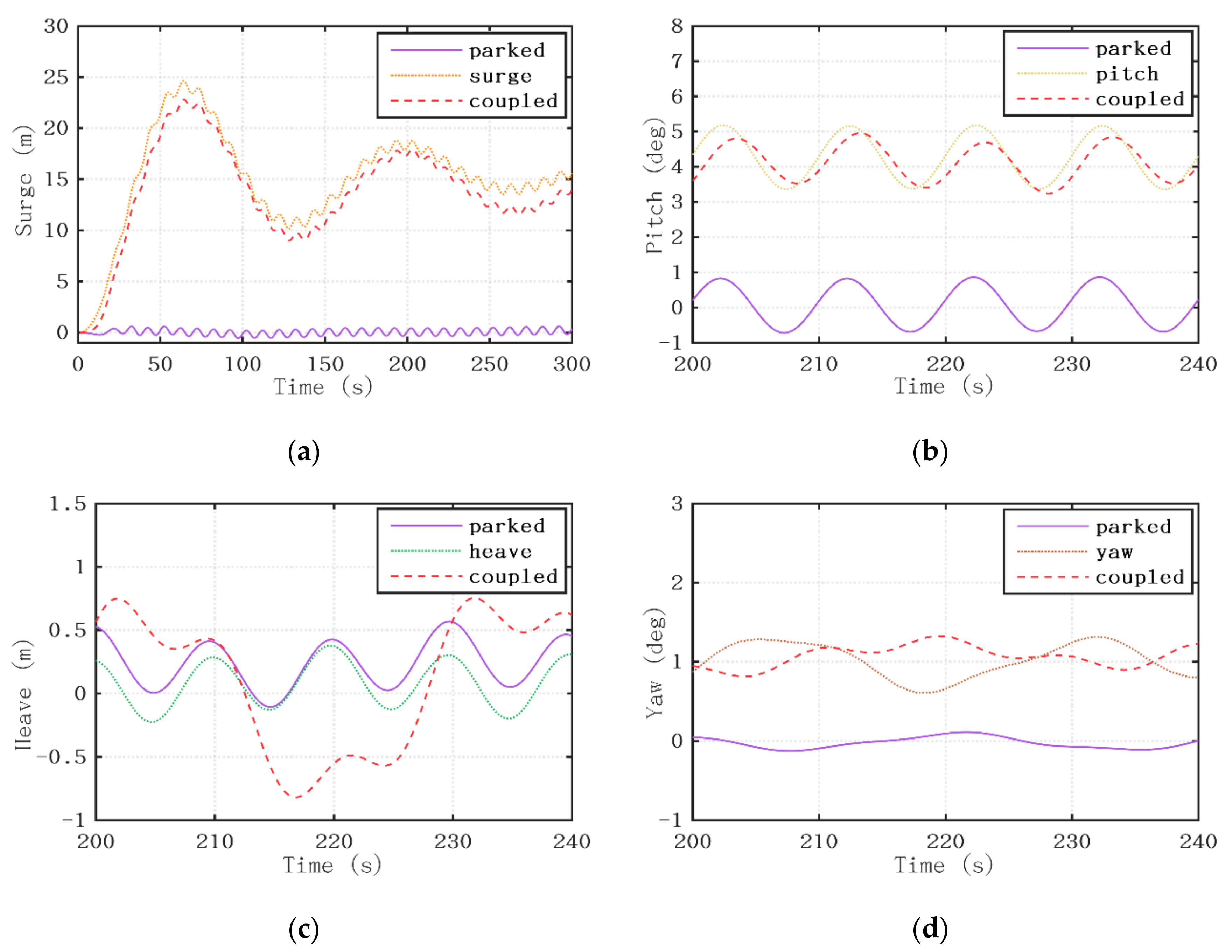
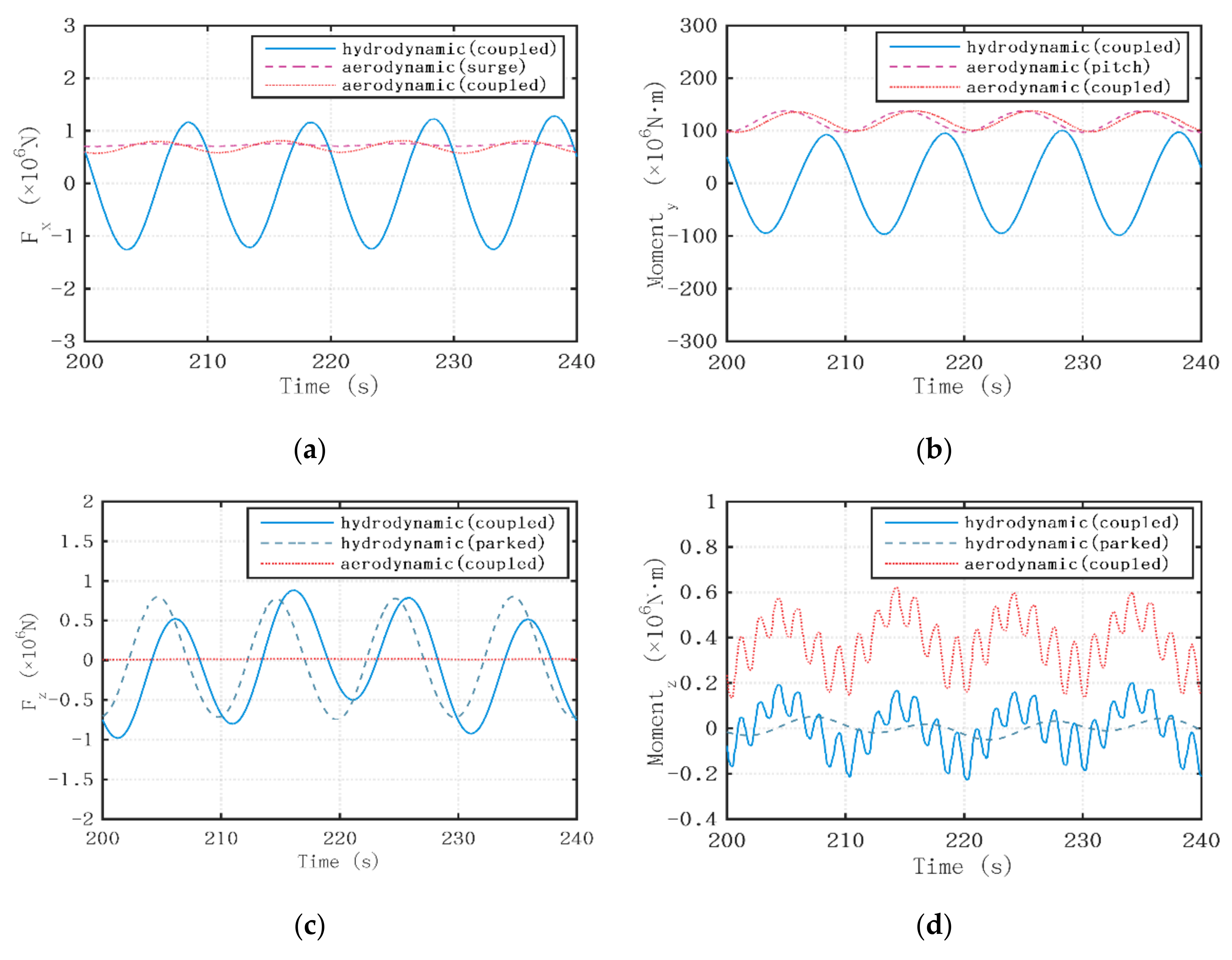
Affected by the aerodynamic forces derived from the wind turbine, the mean surge displacement and average platform pitch angle both significantly increase. A small increase in the platform yaw motion is also found due to the increased yawing moment induced by the asymmetrical distribution of aerodynamic loads. The platform heave displacement decreases because of the vertical aerodynamic force component.
(5)
The motion responses of the FOWT with coupled platform motions are smaller than those with single DOF platform motion, except for the heave motion. The platform heave displacement in coupled condition is much larger than that with single DOF motion, resulting from the greater aerodynamic force component along the vertical direction. The coupling effects between the platform motions along different DOFs are obviously amplified by the aerodynamic loads.
(6)
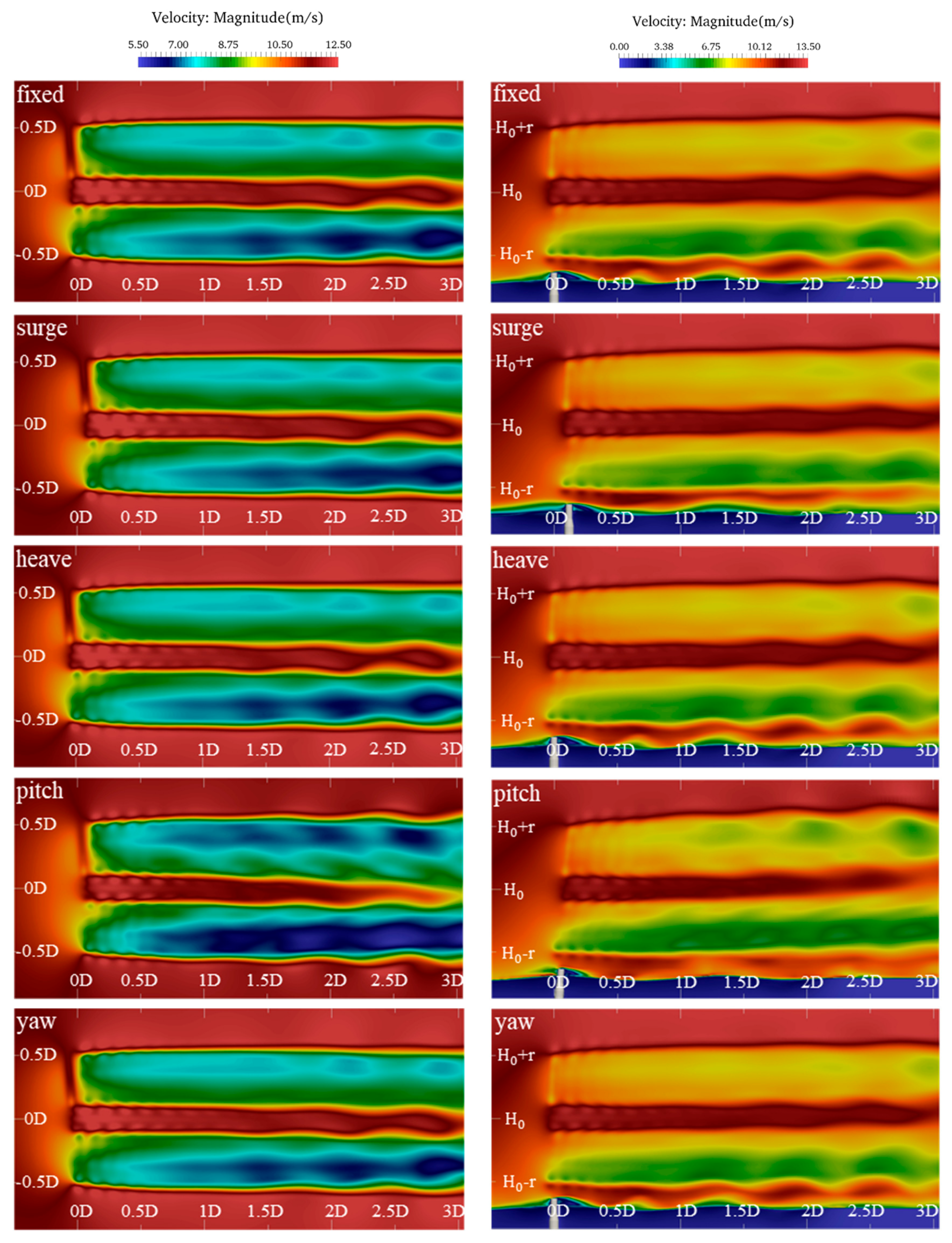
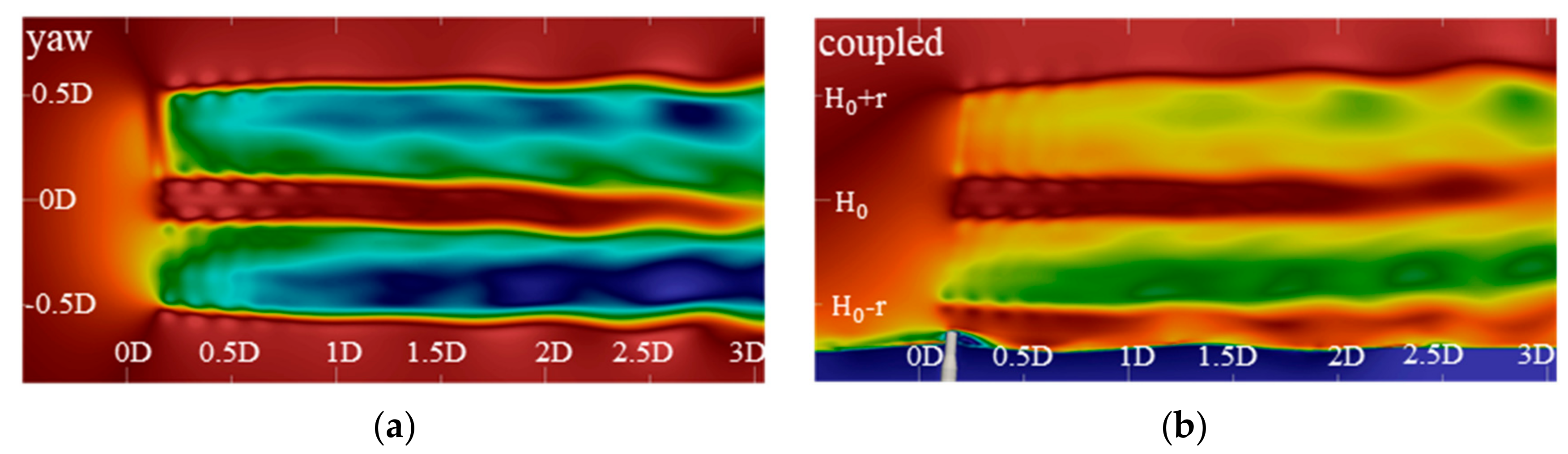
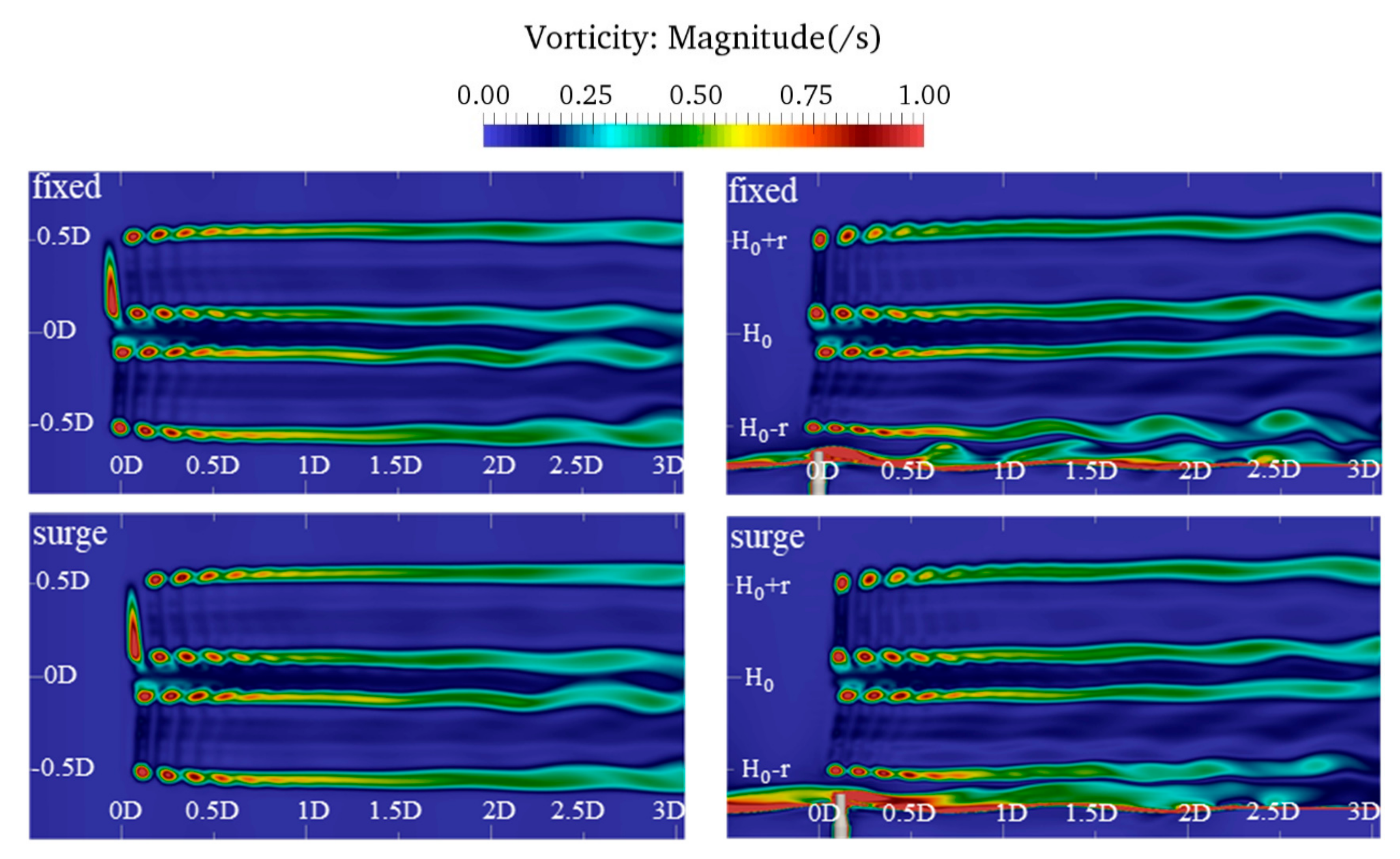
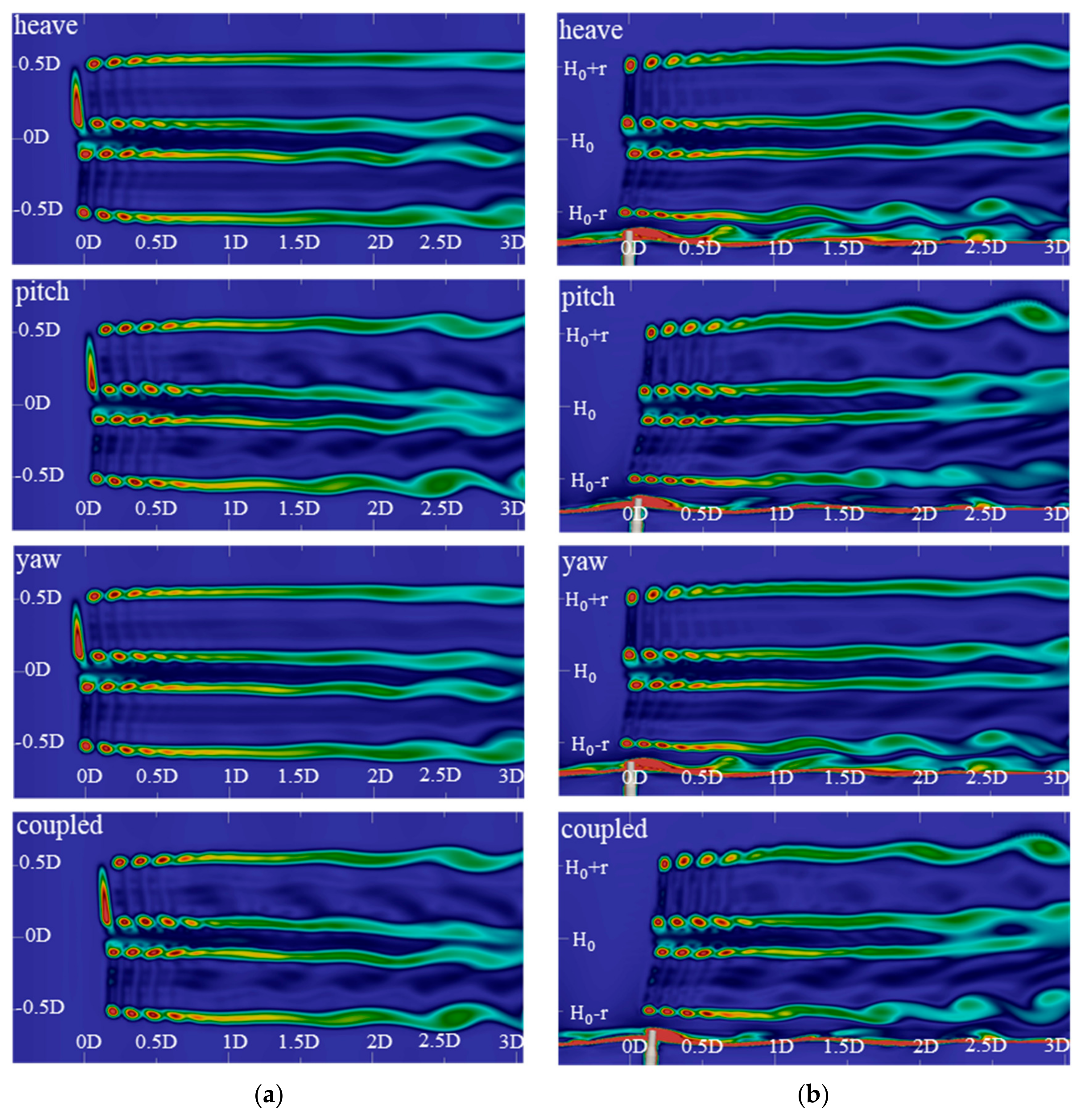
The wake deflection phenomenon is clearly observed in the near wake region when platform pitch motion is considered. The dynamic pitch motion of the floating platform also contributes to the severe wake velocity deficit. Meanwhile, the periodical variation of the platform pitch angle enlarges the wake width and turbulence intensity. Other DOF platform motions including the surge, heave and yaw all have little influence on the wake flow.
The present results and conclusions will help to the further understand the interaction mechanism between the floating platform and the wind turbine and contribute to the development of advanced dynamic controller of the FOWT system. Nevertheless, it is noted that the winds and waves in realistic environment are not always collinear and much more complex than those in the simulations. The blade-pitch controller and rotor-speed regulator are important when the FOWT is in operation, while they are not considered in the present work. Therefore, more numerical simulations will be conducted to further study the coupled aero-hydrodynamic characteristics of the FOWT system with various control strategies under irregular waves and random winds in the future.

Author Contributions

Conceptualization, Y.H., and D.W.; methodology, Y.H., and D.W.; software, Y.H.; validation, Y.H.; formal analysis, Y.H., and D.W.; investigation, Y.H.; resources, D.W.; data curation, Y.H.; writing—original draft preparation, Y.H.; writing—review and editing, Y.H., and D.W.; visualization, Y.H., and D.W.; supervision, D.W.; project administration, D.W.; funding acquisition, D.W. All authors have read and agreed to the published version of the manuscript.

Funding

This work is supported by the National Natural Science Foundation of China (51879159, 51490675, 11432009, 51579145), The National Key Research and Development Program of China (2019YFB1704204), Chang Jiang Scholars Program (T2014099), Innovative Special Project of Numerical Tank of Ministry of Industry and Information Technology of China (2016-23/09) and the Lloyd’s Register Foundation for doctoral students.

Acknowledgments

Sincere thanks to the researchers from the National Renewable Energy Laboratory (NREL) for providing the related floating offshore wind turbine model. This work is supported by the National Natural Science Foundation of China (51879159, 51490675, 11432009, 51579145), The National Key Research and Development Program of China (2019YFB1704204), Chang Jiang Scholars Program (T2014099), Shanghai Excellent Academic Leaders Program (17XD1402300), Innovative Special Project of Numerical Tank of Ministry of Industry and Information Technology of China (2016-23/09), to which the authors are most grateful.

Conflicts of Interest

The authors declare no conflict of interest.

References

  1. Sun, X.; Huang, D.; Wu, G. The current state of offshore wind energy technology development. Energy 2012, 41, 298–312. [Google Scholar] [CrossRef]
  2. Rodrigues, S.; Restrepo, C.; Kontos, E. Trends of offshore wind projects. Renew. Sustain. Energy Rev. 2015, 49, 1114–1135. [Google Scholar] [CrossRef]
  3. Schwanitz, V.J.; Wierling, A. Offshore wind investments—Realism about cost developments is necessary. Energy 2016, 106, 170–181. [Google Scholar] [CrossRef]
  4. Shen, X.; Chen, J.; Hu, P. Study of the unsteady aerodynamics of floating wind turbine. Energy 2018, 145, 793–809. [Google Scholar] [CrossRef]
  5. Hansen, M.O.L.; Sørensen, J.N.; Voutsinas, S. State of the art in wind turbine aerodynamics and aeroelasticity. Prog. Aerosp. Sci. 2006, 42, 285–330. [Google Scholar] [CrossRef]
  6. Sebastian, T.; Lackner, M.A. Development of a free vortex wake method code for offshore floating wind turbines. Renew. Energy 2012, 46, 269–275. [Google Scholar] [CrossRef]
  7. Sebastian, T.; Lackner, M.A. Characterization of the unsteady aerodynamics of offshore floating wind turbines. Wind Energy 2013, 16, 339–352. [Google Scholar] [CrossRef]
  8. Wen, B.; Dong, X.; Tian, X.; Peng, Z.; Zhang, W. Influences of surge motion on the power and thrust characteristics of an offshore floating wind turbine. Energy 2017, 141, 2054–2068. [Google Scholar] [CrossRef]
  9. Wen, B.; Dong, X.; Tian, X.; Peng, Z.; Zhang, W. The power performance of an offshore floating wind turbine in platform pitching motion. Energy 2018, 154, 508–521. [Google Scholar] [CrossRef]
  10. Chen, C.H.; Yu, K. CFD simulations of wave–current-body interactions including green water and wet deck slamming. Comput. Fluids 2009, 38, 970–980. [Google Scholar] [CrossRef]
  11. Tran, T.T.; Kim, D.H.; Song, J. Computational fluid dynamic analysis of a floating offshore wind turbine experiencing platform pitching motion. Energies 2014, 7, 5011–5026. [Google Scholar] [CrossRef]
  12. Tran, T.T.; Kim, D.H. The aerodynamic interference effects of a floating offshore wind turbine experiencing platform pitching and yawing motions. J. Mech. Sci. Technol. 2015, 29, 549–561. [Google Scholar] [CrossRef]
  13. Tran, T.T.; Kim, D.H. A CFD study into the influence of unsteady aerodynamic interference on wind turbine surge motion. Renew. Energy 2016, 90, 204–228. [Google Scholar] [CrossRef]
  14. Lei, H.; Zhou, D.; Lu, J. The impact of pitch motion of a platform on the aerodynamic performance of a floating vertical axis wind turbine. Energy 2017, 119, 369–383. [Google Scholar] [CrossRef]
  15. Liu, Y.; Xiao, Q.; Incecik, A. Investigation of the effects of platform motion on the aerodynamics of a floating offshore wind turbine. J. Hydrodyn. 2016, 28, 95–101. [Google Scholar] [CrossRef] [Green Version]
  16. Li, P.; Cheng, P.; Wan, D.; Xiao, Q. Numerical simulations of wake flows of floating offshore wind turbines by unsteady actuator line model. In Proceedings of the 9th International Workshop on Ship and Marine Hydrodynamics, Glasgow, UK, 26–28 August 2015. [Google Scholar]
  17. Ma, Y.; Hu, Z.Q.; Xiao, L.F. Wind-wave induced dynamic response analysis for motions and mooring loads of a spar-type offshore floating wind turbine. J. Hydrodyn. 2015, 26, 865–874. [Google Scholar] [CrossRef]
  18. Zhao, W.; Wan, D. Numerical study of interactions between phase II of OC4 wind turbine and its semi-submersible floating support system. J. Ocean Wind Energy 2015, 2, 45–53. [Google Scholar]
  19. Robertson, A.; Jonkman, J.; Masciola, M.; Song, H.; Goupee, A.; Coulling, A.; Luan, C. Definition of the Semisubmersible Floating System for Phase II of OC4; National Renewable Energy Laboratory (NREL): Golden, CO, USA, 2014; Available online: https://www.nrel.gov/docs/fy14osti/60601.pdf (accessed on 23 December 2019).
  20. Antonutti, R.; Peyrard, C.; Johanning, L.; Incecik, A.; Ingram, D. An investigation of the effects of wind-induced inclination on floating wind turbine dynamics: Heave plate excursion. Ocean Eng. 2014, 91, 208–217. [Google Scholar] [CrossRef] [Green Version]
  21. Antonutti, R.; Peyrard, C.; Johanning, L.; Incecik, A.; Ingram, D. The effects of wind-induced inclination on the dynamics of semi-submersible floating wind turbines in the time domain. Renew. Energy 2016, 88, 83–94. [Google Scholar] [CrossRef] [Green Version]
  22. Philippe, M.; Babarit, A.; Ferrant, P. Modes of response of an offshore wind turbine with directional wind and waves. Renew. Energy 2013, 49, 151–155. [Google Scholar] [CrossRef] [Green Version]
  23. Huang, Y.; Cheng, P.; Wan, D. Numerical Analysis of a Floating Offshore Wind Turbine by Coupled Aero-Hydrodynamic Simulation. J. Mar. Sci. Appl. 2019, 18, 82–92. [Google Scholar] [CrossRef]
  24. Quallen, S.; Xing, T.; Carrica, P.; Li, Y.; Xu, J. CFD simulation of a floating offshore wind turbine system using a quasi-static crowfoot mooring-line model. J. Ocean Wind Energy 2014, 1, 143–152. [Google Scholar]
  25. Jonkman, J.; Musial, W. Offshore Code Comparison Collaboration (oc3) for Iea Wind Task 23 Offshore Wind Technology and Deployment; Office of Scientific & Technical Information Technical Reports; National Renewable Energy Laboratory: Golden, CO, USA, 2010. [Google Scholar]
  26. Tran, T.T.; Kim, D.H. Fully coupled aero-hydrodynamic analysis of a semi-submersible FOWT using a dynamic fluid body interaction approach. Renew. Energy 2016, 92, 244–261. [Google Scholar] [CrossRef]
  27. Liu, Y.; Xiao, Q.; Incecik, A. Establishing a fully coupled CFD analysis tool for floating offshore wind turbines. Renew. Energy 2017, 112, 280–301. [Google Scholar] [CrossRef] [Green Version]
  28. Cheng, P.; Huang, Y.; Wan, D. A numerical model for fully coupled aero-hydrodynamic analysis of floating offshore wind turbine. Ocean Eng. 2019, 173, 183–196. [Google Scholar] [CrossRef]
  29. Bae, Y.H.; Kim, M.H. Rotor-floater-mooring coupled dynamic analysis of mono-column-TLP-type FOWT (Floating Offshore Wind Turbine). Ocean Syst. Eng. 2011, 1, 95–111. [Google Scholar] [CrossRef]
  30. Bae, Y.H.; Kim, M.H. Rotor-floater-tether coupled dynamics including second-order sum–frequency wave loads for a mono-column-TLP-type FOWT (floating offshore wind turbine). Ocean Eng. 2013, 61, 109–122. [Google Scholar] [CrossRef]
  31. Bae, Y.H.; Kim, M.H. The dynamic coupling effects of a MUFOWT (multiple unit floating offshore wind turbine) with partially broken blade. J. Ocean Wind Energy 2015, 2, 89–97. [Google Scholar] [CrossRef] [Green Version]
  32. Naqvi, S.K. Scale Model Experiments on Floating Offshore Wind Turbines. Master’s Thesis, Worcester Polytechnic Institute, Worcester, MA, USA, 2012. [Google Scholar]
  33. Huijs, F.; Ridder, E.J.; Savenije, F. Comparison of model tests and coupled simulations for a semi-submersible floating wind turbine. In Proceedings of the ASME 2014 33rd International Conference on Ocean, Offshore and Arctic Engineering, San Francisco, CA, USA, 8–13 June 2014. [Google Scholar]
  34. Koo, B.J.; Goupee, A.J.; Kimball, R.W.; Lambrakos, K.F. Model tests for a floating wind turbine on three different floaters. J. Offshore Mech. Arct. Eng. 2014, 136, 020907. [Google Scholar] [CrossRef]
  35. Perez, L.R. Design, Testing and Validation of a Scale Model Semisubmersible Offshore Wind Turbine Under Regular/Irregular Waves and Wind Loads. Master’s Thesis, University of Strathclyde, Glasgow, UK, 2014. [Google Scholar]
  36. Sandner, F.; Amann, F.; Azcona, J. Model building and scaled testing of 5MW and 10MW semi-submersible floating wind turbines. In Proceedings of the EERA DeepWind 2015 Conference, Trondheim, Norway, 4–6 February 2015. [Google Scholar]
  37. Viselli, A.M.; Goupee, A.J.; Dagher, H.J. Model test of a 1: 8-scale floating wind turbine offshore in the gulf of maine. J. Offshore Mech. Arct. Eng. 2015, 137, 041901. [Google Scholar] [CrossRef] [Green Version]
  38. Nielsen, F.G.; Hanson, T.D.; Skaare, B. Integrated dynamic analysis of floating offshore wind turbines. In Proceedings of the 25th International Conference on Offshore Mechanics and Arctic Engineering, Hamburg, Germany, 4–9 June 2006; pp. 671–679. [Google Scholar]
  39. Skaare, B.; Hanson, T.D.; Nielsen, F.G. Importance of control strategies on fatigue life of floating wind turbines. In Proceedings of the ASME 2007 26th International Conference on Offshore Mechanics and Arctic Engineering, San Diego, CA, USA, 10–15 June 2007; pp. 493–500. [Google Scholar]
  40. Larsen, T.J.; Hanson, T.D. A method to avoid negative damped low frequent tower vibrations for a floating, pitch controlled wind turbine. J. Phys. Conf. Ser. 2007, 75. [Google Scholar] [CrossRef]
  41. Jonkman, J. Influence of control on the pitch damping of a floating wind turbine. In Proceedings of the 46th AIAA Aerospace Sciences Meeting and Exhibit, Reno, NV, USA, 7–10 January 2008. [Google Scholar]
  42. Namik, H.; Stol, K. Individual blade pitch control of floating offshore wind turbines. Wind Energy 2010, 13, 74–85. [Google Scholar] [CrossRef]
  43. Bae, Y.H.; Kim, M.H.; Yu, Q.; Kim, K. Influence of control strategy to FOWT hull motions by aero-elastic-control-floater-mooring coupled dynamic analysis. In Proceedings of the Twenty-First International Offshore and Polar Engineering Conference, Maui, HI, USA, 19–24 June 2011. [Google Scholar]
  44. Sørensen, J.N.; Shen, W.Z. Numerical modeling of wind turbine wakes. J. Fluids Eng. 2002, 124, 393–399. [Google Scholar] [CrossRef]
  45. Meng, H.; Lien, F.S.; Li, L. Elastic Actuator Line Modelling for Wake-Induced Fatigue Analysis of Horizontal Axis Wind Turbine Blade. Renew. Energy 2017, 116, 423–437. [Google Scholar] [CrossRef]
  46. Sørensen, J.N.; Shen, W.Z.; Munduate, X. Analysis of wake states by a full-field actuator disc model. Wind Energy 1998, 1, 73–88. [Google Scholar] [CrossRef]
  47. Shen, Z.R.; Cao, H.J.; Wan, D.C. Manual of CFD Solver for Ship and Ocean Engineering Flows: Naoe-FOAM-SJTU; Technical Report for Solver Manual; Shanghai Jiao Tong University: Shanghai, China, 2012. [Google Scholar]
  48. Cao, H.; Wang, X.; Liu, Y.; Wan, D. Numerical prediction of wave loading on a floating platform coupled with a mooring system. In Proceedings of the Twenty-third International Offshore and Polar Engineering Conference, Anchorage, AK, USA, 30 June–5 July 2013. [Google Scholar]
  49. Cao, H.J.; Wan, D.C. Development of multidirectional nonlinear numerical wave tank by naoe-FOAM-SJTU solver. Int. J. Ocean Syst. Eng. 2014, 4, 49–56. [Google Scholar] [CrossRef]
  50. Shen, Z.R.; Ye, H.X.; Wan, D.C. Motion response and added resistance of ship in head waves based on RANS simulations. Chin. J. Hydrodyn. 2012, 27, 621–633. [Google Scholar]
  51. Jonkman, J.; Butterfield, S.; Musial, W.; Scott, G. Definition of A 5-Mw Reference Wind Turbine for Offshore System Development; Office of Scientific & Technical Information Technical Reports; National Renewable Energy Laboratory: Golden, CO, USA, 2009. [Google Scholar]
  52. Bazilevs, Y.; Hsu, M.C.; Akkerman, I.; Wright, K.; Takizawa, K.; Henicke, B.; Spielman, T.; Tezduyar, T.E. 3D simulation of wind turbine rotors at full scale. Part I: Geometry modeling and aerodynamics. Int. J. Numer. Methods Fluids 2011, 65, 207–235. [Google Scholar] [CrossRef] [Green Version]
  53. Jonkman, J. Definition of the Floating System for Phase IV of OC3; USDOE Technical Report; National Renewable Energy Laboratory: Golden, CO, USA, 2010. [Google Scholar]
  54. Han, Z.H.; Li, Y.; Ji, J. Numerical study on 3D steady flow of a 1.3 MW wind turbine considering wind shear factor. J. Chin. Soc. Power Eng. 2011, 31, 779–783. [Google Scholar]
  55. Dolan, D.S.; Lehn, P.W. Simulation model of wind turbine 3p torque oscillations due to wind shear and tower shadow. IEEE T. Energy Conver. 2006, 21, 717–724. [Google Scholar] [CrossRef]
  56. Spera, D.A. Wind Turbine Technology: Fundamental Concepts of Wind Turbine Engineering (Vol. 3); ASME Press: New York, NY, USA, 1994. [Google Scholar]
  57. Huang, Y.; Wan, D.; Hu, C. Coupled Aero-Hydrodynamic Analysis on a Floating Offshore Wind Turbine Under Extreme Sea Conditions. In Proceedings of the 27th International Ocean and Polar Engineering Conference, San Francisco, CA, USA, 25–30 June 2017. [Google Scholar]
Figure 1. Coordinate systems for coupled analysis of the FOWT [45].
Sustainability 12 00246 g001
Figure 2. Velocity components at cross-sectional airfoil element defined in the blade-aligned coordinate system.
Sustainability 12 00246 g002
Figure 3. The framework diagram of naoe-FOAM-SJTU solver.
Sustainability 12 00246 g003
Figure 4. Wind and wave loads acting on the FOWT system.
Sustainability 12 00246 g004
Figure 5. Calculation procedure of coupled simulation for the FOWT.
Sustainability 12 00246 g005
Figure 6. The NREL 5-MW wind turbine mounted on OC3-Hywind spar.
Sustainability 12 00246 g006
Figure 7. Mooring lines arrangement.
Sustainability 12 00246 g007
Figure 8. Overall view of the computational domain.
Sustainability 12 00246 g008
Figure 9. Computational domain mesh. (a) vertical section; (b) cross section.
Sustainability 12 00246 g009
Figure 10. Time history curves of aerodynamic loads with different mesh resolutions. (a) rotor power; (b) thrust.
Sustainability 12 00246 g010
Figure 11. The additional velocity components induced by platform motions. (a) vertical plane; (b) horizontal plane.
Sustainability 12 00246 g011
Figure 12. Comparisons of velocity components experienced by the blade section at 0.8r for fixed case and surge case. (a) axial velocity; (b) tangential velocity.
Sustainability 12 00246 g012
Figure 13. Wind speed distribution along the height.
Sustainability 12 00246 g013
Figure 14. Platform surge responses in surge case.
Sustainability 12 00246 g014
Figure 15. Comparisons of velocity components experienced by the blade section at 0.8r under shear wind and uniform wind. (a) axial speed; (b) tangential speed.
Sustainability 12 00246 g015
Figure 16. Time-history curves of the local attack angle and the local relative wind speed experienced by the blade section at 0.8r in fixed case and surge case. (a) local attack angle; (b) local relative wind speed.
Sustainability 12 00246 g016
Figure 17. Comparisons of aerodynamic loads for fixed case and surge case. (a) rotor power; (b) thrust.
Sustainability 12 00246 g017
Figure 18. Comparisons of speed components experienced by the blade section at 0.8r for fixed case, pitch case and coupled case. (a) axial speed; (b) tangential speed.
Sustainability 12 00246 g018
Figure 19. Platform pitch responses in pitch case.
Sustainability 12 00246 g019
Figure 20. Time-history curves of the local attack angle and the local relative wind speed experienced by the blade section at 0.8r in fixed case, pitch case and coupled case. (a) local attack angle; (b) local relative wind speed.
Sustainability 12 00246 g020
Figure 21. Comparisons of aerodynamic loads for fixed case, pitch case and coupled case. (a) rotor power; (b) thrust.
Sustainability 12 00246 g021
Figure 22. Time-history curves of the local attack angle and the local relative wind speed experienced by the blade section at 0.8r in fixed case, heave case and yaw case. (a) local attack angle; (b) local relative wind speed.
Sustainability 12 00246 g022
Figure 23. Comparisons of aerodynamic loads for fixed case, heave case and yaw case. (a) rotor power; (b) thrust.
Sustainability 12 00246 g023
Figure 24. Platform yaw angle and yaw angular velocity in yaw case.
Sustainability 12 00246 g024
Figure 25. Platform heave displacement and heave velocity in heave case.
Sustainability 12 00246 g025
Figure 26. Comparisons of maximum and minimum values of the aerodynamic loads under different DOF platform motions. (a) rotor power; (b) thrust.
Sustainability 12 00246 g026
Figure 27. Comparisons of platform motions in different simulation cases. (a) surge; (b) pitch; (c) heave; (d) yaw.
Sustainability 12 00246 g027
Figure 28. Comparisons of the aerodynamic and hydrodynamic loads acting on the floating platform. (a) axial force along x axis; (b) bending moment about y axis; (c) axial force along z axis; (d) bending moment about z axis.
Sustainability 12 00246 g028
Figure 29. Comparisons of instantaneous flow velocity (T = 240 s) in wake field for different cases. (D = 126 m is the rotor diameter; H0 = 90 m is the hub height; r = 63 m is the rotor radius). (a) horizontal plane (z = 90 m); (b) vertical plane (y = 0 m).
Sustainability 12 00246 g029aSustainability 12 00246 g029b
Figure 30. Comparisons of instantaneous vorticities (T = 240 s) in the wake field for different cases (D = 126 m is the rotor diameter; H0 = 90 m is the hub height; r = 63 m is the rotor radius). (a) horizontal plane (z = 90 m); (b) vertical plane (y = 0 m).
Sustainability 12 00246 g030aSustainability 12 00246 g030b
Table 1. NREL-5MW wind turbine gross parameters.
ItemValue
Rating5 MW
Rotor orientation, ConfigurationUpwind, 3 Blades
Rotor, Hub diameter126 m, 3 m
Hub height90 m
Cut-in, Rated, Cut-out wind Speed3 m/s, 11.4 m/s, 25 m/s
Cut-in, Rated Rotor speed 6.9 rpm, 12.1 rpm
Overhang, Shaft-tilt, Pre-cone angle5 m, 5°, 2.5°
Table 2. OC3-Hywind spar platform main properties.
ItemValue
Depth to platform base below SWL (Total Draft)120 m
Elevation to platform top (Tower base) above SWL10 m
Depth to top of taper below SWL4 m
Depth to bottom of taper below SWL12 m
Platform diameter above/below taper6.5 m, 9.4 m
Table 3. Mooring system properties.
ItemValue
Number of mooring lines3
Angle between adjacent lines120°
Depth to anchors below SWL (water depth)320 m
Depth to fairleads below SWL70.0 m
Radius to anchors from platform centerline853.87 m
Radius to fairleads from platform centerline5.2 m
Table 4. Load case parameters.
Case NamePlatform Motion ModeWind Turbine State
fixedfixedRotating
surgesurgeRotating
heaveheaveRotating
pitchpitchRotating
yawyawRotating
parkedsurge, heave, pitch, yawParked
coupledsurge, heave, pitch, yawRotating
Table 5. Mean values of the aerodynamic loads averaged from 40 s~50 s.
GridTotal Grid Number
(Million)
Rotor Power
(MW)
Thrust
(kN)
Coarse mesh1.335.73 (9.2%)747 (4.5%)
Medium mesh3.505.31 (1.3%)720 (0.4%)
Fine mesh9.705.24 (-)715 (-)
Table 6. Summary of the time-averaged (200 s~240 s) aerodynamic loads in different simulation cases.
CasesRotor Power (MW)Thrust (kN)
MaxMinMeanAmp.MaxMinMeanAmp.
fixed5.3635.2765.3240.087723.8718.1721.35.7
surge5.8965.0455.4910.851756.9703.2731.853.7
heave5.3615.2845.3220.077723.7718.6721.15.1
pitch6.9563.3135.0723.643817.1577.1699.1240
yaw5.3605.2735.3210.087723.5717.8720.95.7
coupled6.9613.3095.1513.652817.4577.2705.1240.2

