Article

Direct Power Control of Matrix Converter-Fed DFIG with Fixed Switching Frequency

by
Arzhang Yousefi-Talouki
1,
Shaghayegh Zalzar
2 and
Edris Pouresmaeil
3,*
1
ABB Oy, Valimopolku 4, 00380 Helsinki, Finland
2
Department of Energy, Politecnico di Torino, 10129 Turin, Italy
3
Department of Electrical Engineering and Automation, Aalto University, 02150 Espoo, Finland
*
Author to whom correspondence should be addressed.
Sustainability 2019, 11(9), 2604; https://doi.org/10.3390/su11092604
Submission received: 27 March 2019 / Revised: 23 April 2019 / Accepted: 25 April 2019 / Published: 6 May 2019
(This article belongs to the Special Issue Power Electronics for Renewable Energy Systems)

Abstract

:
In this paper, a direct power control (DPC) technique is proposed for matrix converter-fed grid-connected doubly fed induction generators (DFIGs). In contrast to what has been investigated in the past for direct torque control (DTC) or DPC of matrix converter-fed DFIGs, the active and reactive powers are regulated in a fixed switching frequency using indirect space vector modulation (ISVM) technique. Hence, designing input filters for matrix converters (MCs) becomes convenient. In addition, the reactive component of input side of MC is controlled which leads to reduction of distortion in grid current waveform. Also, an extensive discussion is addressed for nonlinear voltage errors of MC that may cause inaccurate power control. Simulation results done in MATLAB/Simulink show the effectiveness of the proposed method.

1. Introduction

In recent decades, there has been a growing interest in investing in renewable energy sources and these resources are supposed to play a key role in power generation due to enviromental and geopolitical concerns [1,2,3,4]. Among different renewable energy sources, wind based energy production has drawn widespread research attentions and also has been proliferated in to the industry. Wind turbine-based doubly fed induction generators (WT-DFIGs) have been extensively used in wind energy conversion systems (WECSs) due to different advantages such as variable speed operation, lower converter ratings, and lower power loss compared to direct connected generators [5]. A broad research field has been addressed in the literature in control of output power of DFIGs, which can be mainly divided into two categories: vector control (VC) schemes and direct power control (DPC) techniques. A VC method for power control of DFIG has been introduced in [5], where a mathematical model was developed to decouple output active and reactive power of stator. In [6] a method was proposed to independently control active and reactive powers generated or absorb by DFIG. Both aforementioned methods work on synchronous d q plane fixed to stator voltage. Although VC methods have shown good performances; however, since they are dependent to the parameters of DFIG, the control schemes becomes prone to error with parameters variations and also in addition the controller is complicated and very precise current control loop tuning is demanded. In turn, DPC technique which was proposed for the first time in [7] for a DFIG supplied with a back-to-back converter, is independent of model parameters and also has better dynamic performance compared to VC method. This method was inspired by the direct torque and flux control (DTFC) of induction motors [8] and instead of torque and flux control variables, active and reactive powers are regulated using hysteresis controllers. Analogous to DTC method, large power ripples and variable switching frequency were the two major drawbacks of this control technique. To tackle these problems, various methods have been reported in the literature such as space vector modulation (SVM), predictive control, sliding mode control, etc. [9,10,11,12,13]. In [9] a DPC method was proposed in which the hysteresis control loops were eliminated and instead the required rotor voltage was calculated in a fixed switching frequency based on rotor position, stator flux linkage, and the error between set points and observed powers. Then the rotor side converter is commanded based on these calculated voltages. A model-based predictive DPC technique was proposed in [10], where the active and reactive powers of stator are predicted in one sampling frequency and based on this prediction the rotor voltage is calculated and then appropriate PWM signal is commanded. A sliding mode DPC method was proposed in [11], where the performance of DGIG in balanced and unbalanced grids were investigated. A predictive DTC method for DFIG was addressed in [12], where reducing the ripples of electromagnetic torque and stator flux was the main aim of this work. In [13] the behavior of DFIG under unbalanced grid voltage conditions was extensively studied and a DPC control technique was proposed as being appropriate to overcome this condition.
Matrix converter (MC), as a three-phase to three-phase converter, has different merits compared to conventional back-to back converters, such as lack of bulky dc link capacitors, lower volume and size, high quality output power wave forms, and bidirectional power flow. Due to their lack of bulky electrolytic dc-link capacitors, matrix converters are attractive alternatives for the applications where low volume and high reliability are important. Due to these advantages, the application of MCs are extended from electrical drives to grid-connected renewable resources [14,15,16,17].
In [14] a comprehensive review has been done for matrix converter technology including different modulation schemes and commutation methods. In [15], the indirect space vector modulation of matrix converters was presented for the first time. A self-commissioning technique was proposed in [16] capable of identifying the matrix converter nonlinear voltage errors. In [17], the application of matrix converters in sensorless control of synchronous reluctance motor drives was investigated and the effect of nonlinear voltage errors on the control was analyzed. Also, the application of matrix converters in wind turbine based generators have attracted researchers’ attention in recent years [18,19,20,21]. In [18], the active and reactive power diagrams of DFIGs fed by matrix converters were studied for different wind speeds and the capability of this generation system to deliver the maximum powers was analyzed. A maximum power tracking strategy was proposed in [19] based on voltage oriented vector control for WECSs in which a permanent magnet synchronous generator is connected to grid through a three-phase to three-phase MC. A control technique along with stability analysis has been done in [20] for quasi-Z-source MCs as a grid interface in WECSs. Also, in [21] a stability analysis has been done for a 4 kW matrix converter-fed DFIG.
Despite the aforementioned advantages of MCs and DPC method, to the best of authors knowledge, there are only a few references hitherto, reporting the DPC or DTC of MC-fed DFIGs. In [22,23], a DPC method was used for active and reactive power regulation aiming at power ripple reduction using MC space voltage vectors. A DTC method was proposed in [24] which reactive power and electromagnetic torque were the control variables to be regulated using MC voltage vectors. However, all the above methods work with variable switching frequency, since hysteresis controllers are employed in these techniques.
In this paper, a direct power control technique is presented for MC-fed DFIGs which work at constant switching frequency. Active and reactive powers are regulated using the ISVM of matrix converters, where the input current vectors and output voltage vectors are commanded simultaneously based on the input and output current and voltage sectors. In addition, the unity input power factor of MC is analyzed and it is shown that reactive power injection/absorption to/from the grid can be controlled. Furthermore, the nonlinearities of matrix converters that may cause inaccurate power regulation are investigated in details. Extensive simulations and analysis are presented to show the effectiveness of the proposed method.

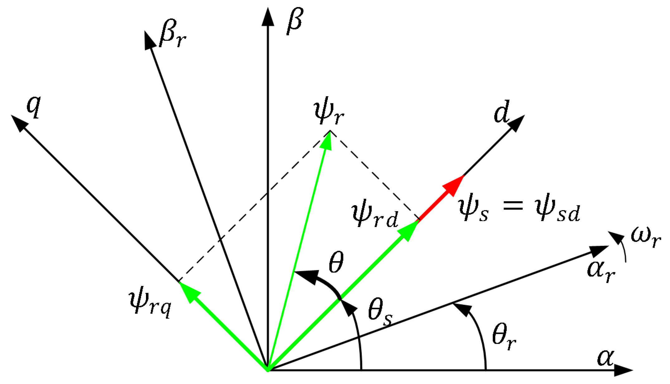
2. Direct Power Control Theory
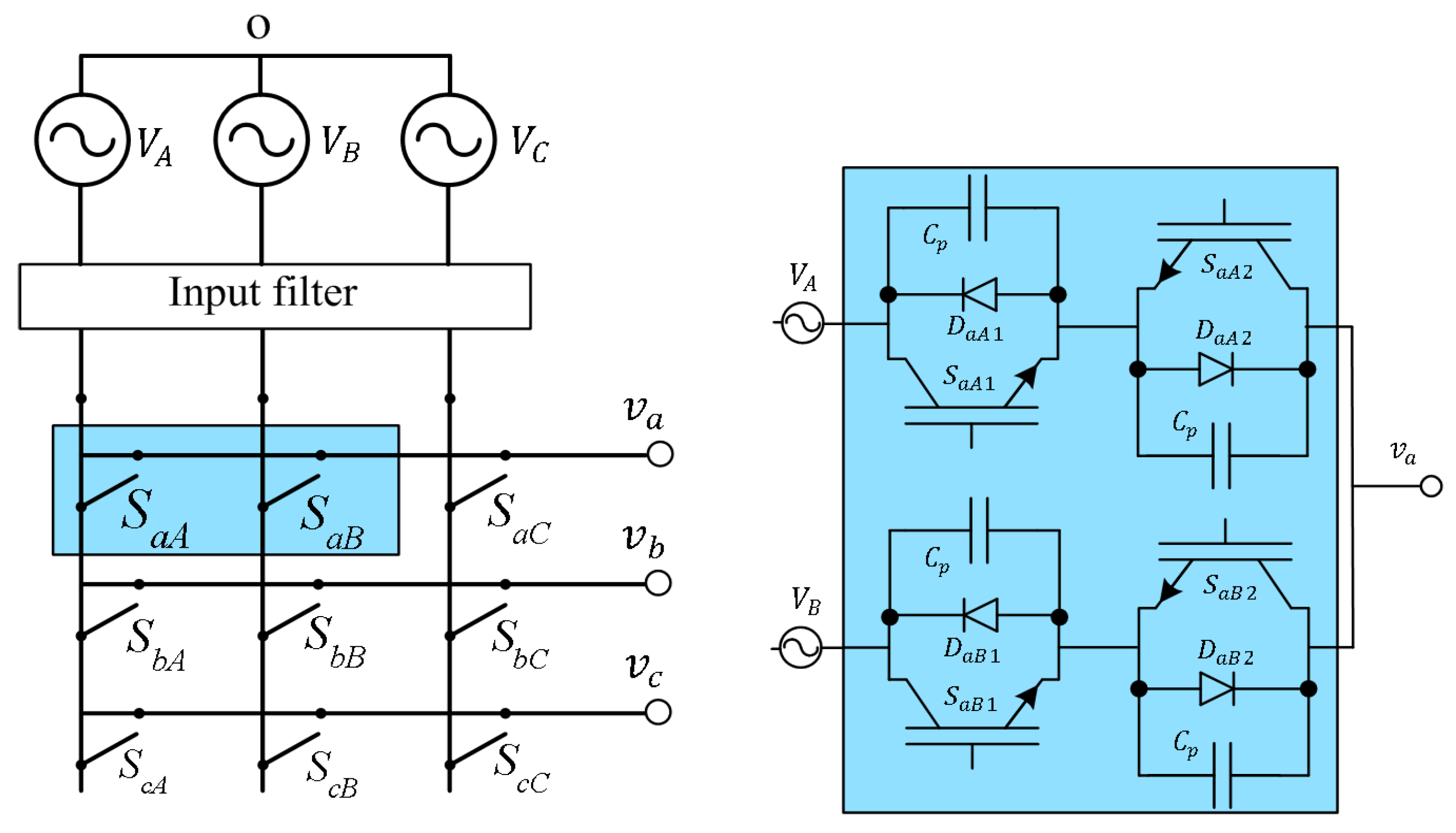
Figure 1 shows the DFIG circuit in d q synchronous frame [7], where ω 1 denotes for synchronous speed, ω r stands for rotor speed, and superscript s expresses the synchronous frame. R r and R s are rotor and stator resistances, respectively. L m is mutual inductance and L σ r and L σ s express the rotor and stator leakage inductances, respectively. Eventually, ψ r and ψ s denote for rotor and stator flux, respectively. Rotor and stator flux in synchronous d q frame is illustrated in Figure 2, where α β and α r β r are stationary and rotor frames, respectively. θ s and θ r stand for stator flux and rotor angles, respectively.
According to Figure 1, the stator voltage vector can be drived as (1). Assuming that the staor flux lies on d-axis (see Figure 2) and also under balance grid the stator flux is constant (derivative is zero), Equation (1) can be expressed as (2). The stator resistance is neglected in this equarion.
V s s = R s I s s + d ψ s s d t + j ω 1 ψ s s
V s s = j ω 1 ψ s d
On the other hand, using the equivalent circuit shown in Figure 1, rotor and stator fluxes in d q frame are obtained as (3) and (4), where L s = L σ s + L m , L r = L σ r + L m . Using these two equations, stator current in synchronous frame is achieved as (5), where σ = ( L s L r L m 2 ) / L s L r .
ψ r s = L r I r s + L m I s s
ψ s s = L s I s s + L m I r s
I s s = L r ψ s s L m ψ r s L s L r L m 2 = ψ s s σ L s L m ψ r s σ L s L r
The input active and reactive power from the grid to DFIG is calculated using Equation (6) [25].
P s j Q s = 3 2 V s s × I s s ^
By replacing (2) and (5) in (6), Equation (7) is obtained, where k σ = 1.5 L m / ( σ L s L r ) .
P s = k σ ω 1 ψ s d ψ r q Q s = k σ ω 1 ψ s d ( ψ r d L r L m ψ s d )
As previously stated, the stator flux is considered constant. Therefore, the changes of powers in a constant sample time T s can be expressed as (8).
Δ P s = k σ ω 1 ψ s d Δ ψ r q Δ Q s = k σ ω 1 ψ s d Δ ψ r d
Noting the rotor side of DFIG circuit in Figure 1 and with a simple KVL, the following equation can be explicitly obtained, where ω s = ω 1 ω r is the slip frequency.
d ψ r s d t = V r s R r I r s + j ω s ψ r s
Neglecting the effect of rotor resistance and with projection of (9) into the synchronous d q reference frame, the changes of rotor flux in d q -axis are obtained as (10).
Δ ψ r d = V r d T s + ω s ψ r q T s Δ ψ r q = V r q T s ω s ψ r d T s
Replacing (10) in (8) and after a straightforward manipulation, the following equation is derived.
V r d = Δ Q s k σ ω 1 ψ s d T s ω s ψ r q V r q = Δ P s k σ ω 1 ψ s d T s + ω s ψ r d
Finally, using Equations (7) and (11), rotor voltage in synchronous d q frame is deduced as (12). It is concluded from (12) that the reactive power variation is regulated using d-axis voltage, while active power is controlled via q-axis channel.
V r d = 1 T s Δ Q s k σ ω 1 ψ d s + ω s P s k σ ω 1 ψ d s V r q = 1 T s Δ P s k σ ω 1 ψ d s + ω s ( Q s k σ ω 1 ψ d s + L r L m ψ d s )
The general schematic diagram of DPC of MC-fed DFIG is illustrated in Figure 3. As seen, the reference voltage vectors in d q frame ( V r d q ) are transfered to rotor stationary frame ( α r β r ) and then are fed to indirect space vector modulation. P s and Q s are instantaneous active and reactive powers, Δ P s = P s * P s and Δ Q s = Q s * Q s are the power variations in one sample time, where P s * and Q s * are the desired power set points.

3. Matrix Converter

Matrix converter is a three-phase to three-phase ac/ac converter as shown in Figure 4, which consists of nine bidirectional switches so that each switch connects one phase to one input phase. In this work, an ISVM modulation is considered to combine the output voltage and input current vectors of the converter. In addition, it has been proved in [26,27,28] that inverter nonlinear voltage errors including dead time and voltage drop on IGBTs may cause imprecise current or power control. Therefore, these errors must be identified and precisely compensated for. Analogous to conventional voltage source inverters, matrix converters also suffer from nonlinear voltage errors due to commutations between input phases. A four step current-based commutation (FS-CBC) is adopted in this work which will be analyzed along with its correspondent nonlinear voltage error called edge uncertainty [17].

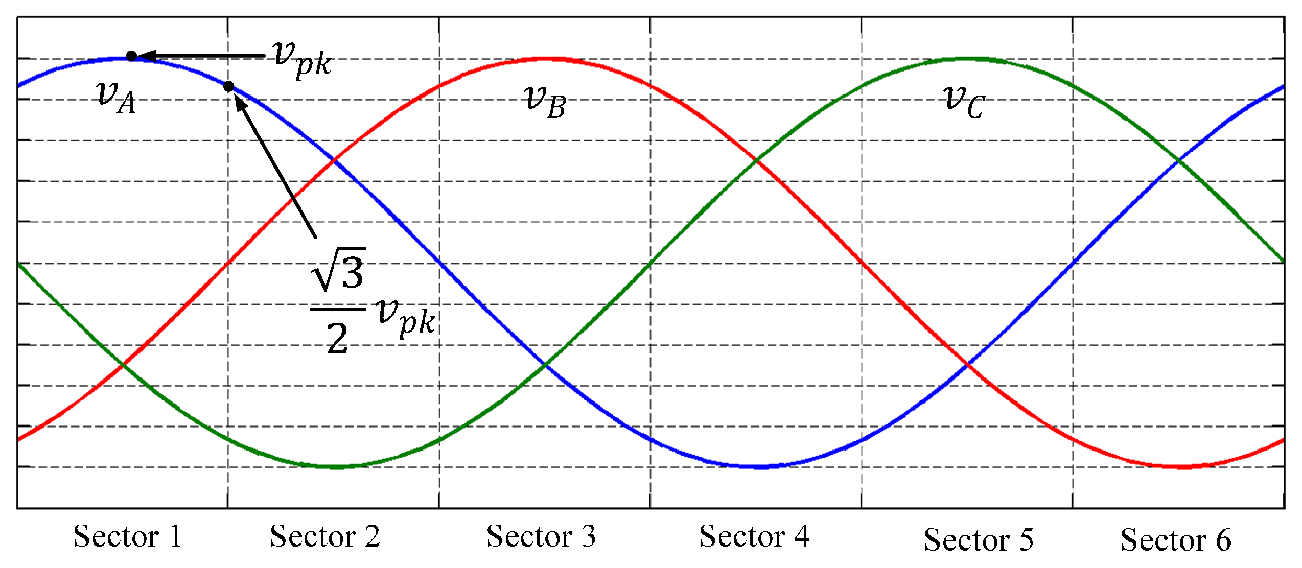
3.1. Indirect Space Vector Modulation

Indirect space vector modulation (ISVM) of matrix converters was proposed for the first time in [15]. In this modulation technique, the input current and output voltage vectors are combined simultaneously. The input and output vectors of MCs are illustrated in Figure 5, where θ o * and v o * are the desired phase angle and amplitude of output vectors. In fact, this voltage vector is V r d q voltage after transformation to rotor stationary frame, as shown in Figure 3. In addition, V i n and I i n are the input voltage and current vectors, before input filter of MC. θ i n * stands for phase angle of V i n and I m c denotes input current vector. Δ θ represents displacement angle among V i n and I m c . In ISVM, I m c is controlled so that to lag V i n by the Δ θ angle to compensate the impact of input filters to obtain unity input power factor.
In ISVM technique, the matrix converter is split into an artificial voltage source rectifier (VSR) and a fictitious voltage source inverter (VSI), as reported in Figure 6. The phase angle of input current ( θ i n * Δ θ ) is controlled using VSR, while v o * and θ o * are modulated by means of VSI.
For further investigation it is supposed that both output and input vectors are in sector ① (see Figure 5). With this assumption, the virtual p n rail of the VSR can be V A B , V A C , or zero. On the other hand, for VSI stage, the output vector can be pnn, ppn, or zero. Therefore, with combination of VSR and VSI stages five states can be obtained: p n n V A C , p n n V A B , p p n V A C , p p n V A B , and zero. For instance, the combination of p p n V A C means that in VSR stage, the virtual P rail is linked to the input phase A (IP-A), and virtual n rail is linked to the input phase C (IP-C). On the VSI stage, output phases b (OP-b) and a (OP-a) are linked to the virtual p rail, and output phase c (OP-c) is connected to the virtual n rail. Hence, their combination expresses that OP-a and OP-b are connected to the IP-A, and OP-c is connected to the IP-C. The projection of this explanation into the real MC of Figure 4, means that for this example switches S a A , S b A , and S c C are ON.
Using these output and input vectors, duty cycles are calculated as expressed from (13) to (17). It is noted that subscripts μ and ν denote for the duty cycles for two adjacent vectors in each sector for VSI stage. Similarly, subscripts δ and γ stand for duty cycles of two adjacent vectors in each sector in VSR stage.
d μ γ = d μ · d γ = 2 3 | V o * | | V i n | sin ( π 3 θ i n * ) sin ( π 3 θ o * )
d μ δ = d μ · d δ = 2 3 | V o * | | V i n | sin ( θ i n * ) sin ( π 3 θ o * )
d ν δ = d ν · d δ = 2 3 | V o * | | V i n | sin ( θ i n * ) sin ( θ o * )
d ν γ = d ν · d γ = 2 3 | V o * | | V i n | sin ( π 3 θ i n * ) sin ( θ o * )
d 0 = 1 ( d μ γ + d μ δ + d ν δ + d ν γ )

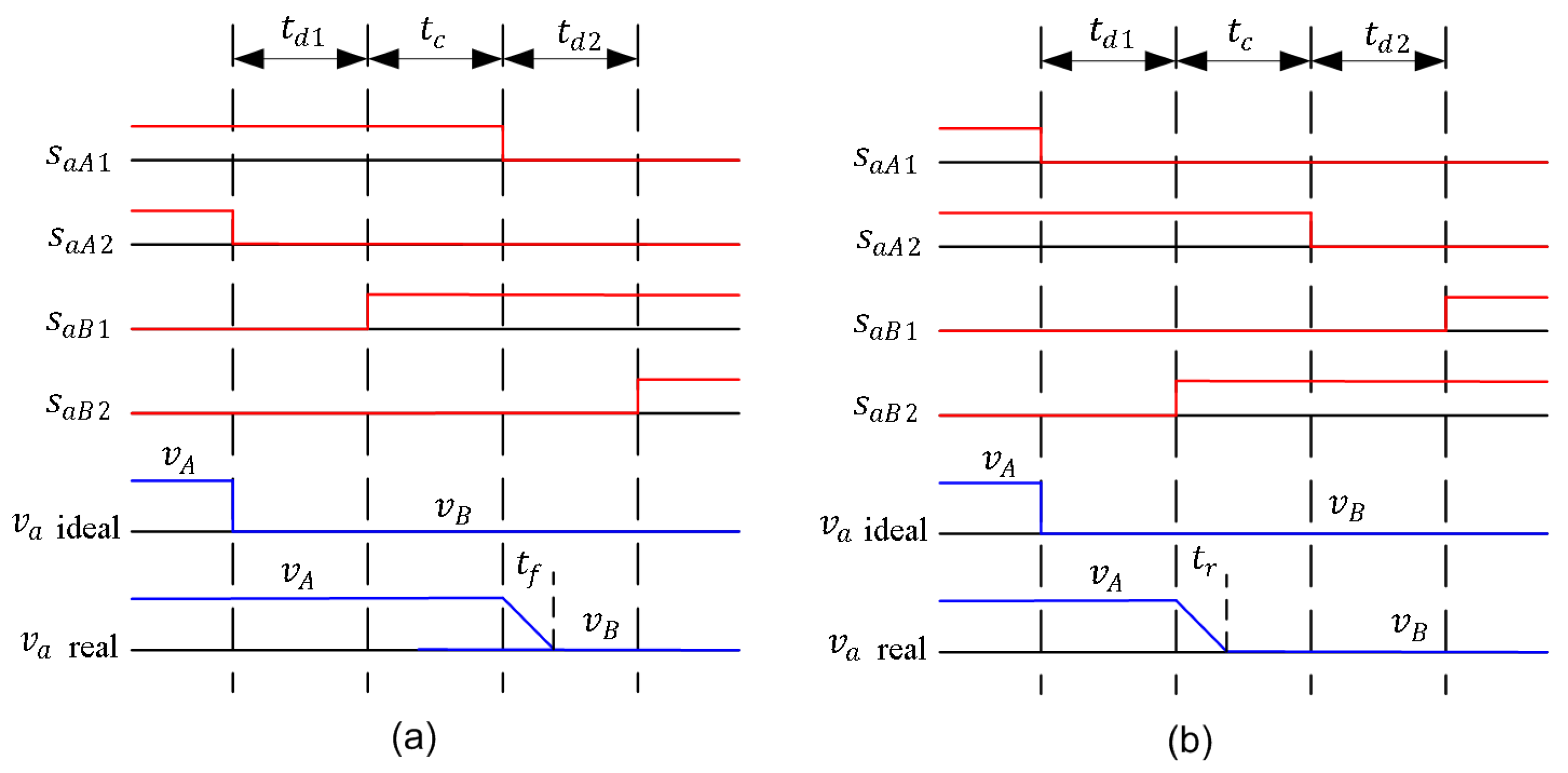
3.2. Four Step Current-Based Commutation (FS-CBC) and Edge Uncertainty (EU) Effect

In matrix converters, when output phase connection is changed between different input phases, a voltage error is produced because of commutations that is called as edge uncertainty voltage effect. Considering Figure 4 and under the assumption that OP-a is connected to the IP-A and then changes to the IP-B, the FS-CBC can be illustrated as in Figure 7, where the commutation is reported for positive (a) and negative (b) output phase current, under the assumption that V A > V B . t c denotes commutation time, t d 1 and t d 2 are delay times, t r and t f are IGBTs rising and falling times, respectively. As an example in Figure 7a it is seen that at fist step of commutation switch S a A 2 disconnects but still the current conducts through the switch S a A 1 . At second step, S a B 1 connects, but since V A > V B and output current is positive, the current is again conducted through switch S a A 1 . At the third step, switch S a A 1 is disconnected and a hard commutation happens and output phase a is connected to the input phase B. At step four, switch S a B 2 is connected and bi-directional power flow is obtained. It is seen that there is a time-area voltage error between ideal and actual IGBT commutation which are expressed as (18) and (19), where E U stands for edge uncertainty voltage error. Also, commutation from IP-B to IP-A can be analyzed in the same manner, which is not discussed here [17].
E U A B ( i a > 0 ) = v * v = V A B ( t d 1 + t c + t f / 2 )
E U A B ( i a < 0 ) = v * v = V A B ( t d 1 + t r / 2 )
By extending this analysis into one switching cycle and assuming that input and output vectors of matrix converter are in sector ① and output phase current is positive, Figure 8 is obtained.
Considering Figure 8, the output phase voltage for phase a ( v a ) for both ideal and real IGBT is expressed as (20) and (21). As can be concluded, a voltage error exists among real and ideal cases which is obtained as (22), where v * and v are reference and actual voltages, respectively.
v a ( i d e a l ) = V A ( T P W M T 0 ) T P W M
v a ( r e a l ) = V A ( T P W M T 0 ) T P W M + 3 V A ( t c + t f / 2 t r / 2 ) T P W M
E U = v * v = 3 V A ( t c + t f / 2 t r / 2 ) T P W M
If the above discussion is extended to all input and output voltage sectors, a general equation for edge uncertainty voltage error is obtained as (23), where i and j stand for output and input phases. It is concluded from this equation that edge uncertainty voltage error is dependent to the amplitude of input phase voltage and sign of output phase current, and also inversely is proportional to PWM switching time interval. The nonlinear voltage errors for all input sectors are tabulated in Table 1. In addition, the input phase voltages and their corresponding input sectors are illustrated in Figure 9.
E U i = 3 V j ( t c + t f / 2 t r / 2 ) T P W M · s i g n ( i i ) , j = A , B , C , i = a , b , c

3.3. On-State Voltage Drop

Since in matrix converters, one diode and one IGBT are conducting at any time, the on-state voltage drop ( V D i ) is modeled as (24), where V t h is a forward threshold voltage of power device and R d accounts for the average resistance of diode and IGBT in series.
V * V = V D i = 2 V t h s i g n ( i i ) + R d i i , i = a , b , c

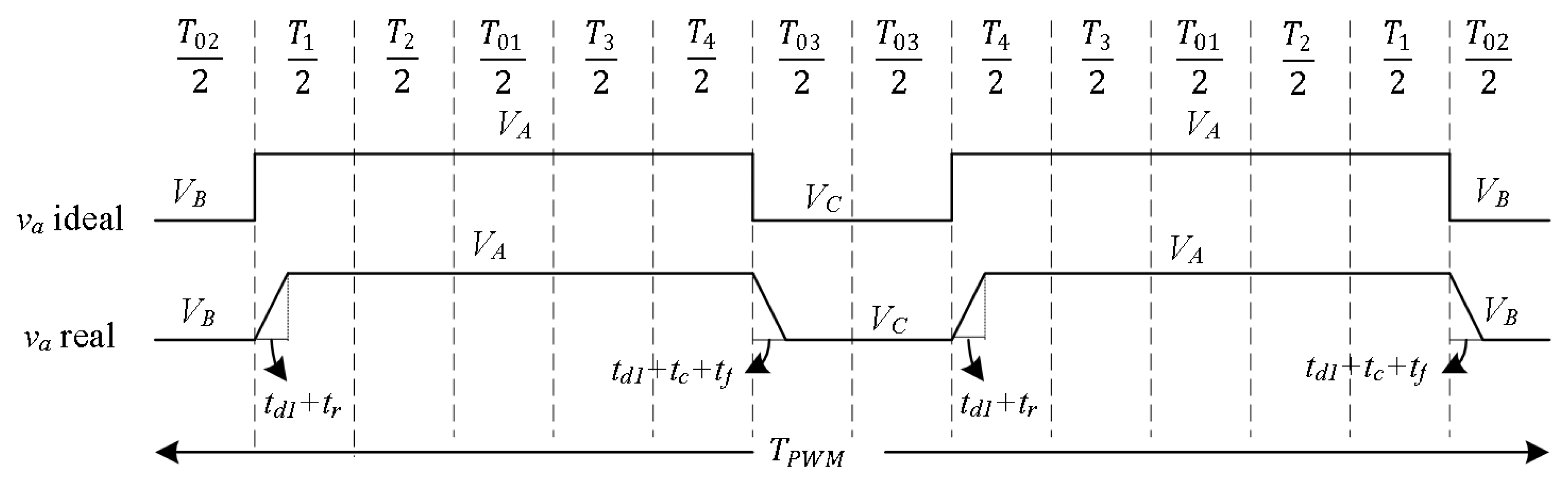
3.4. Overall Voltage Errors

The overall voltage error in matrix converters is obtained by adding edge uncertainty voltage error ( V E U i ) to on-state voltage drop ( V D i ), as expressed as (25).
v e r r , i = v * v = V D i + E U i
As seen from Equation (24), the on-state voltage error consists of one nonlinear part and one resistive voltage drop which is linear part. Therefore, Equation (25) can be extended to (26)
v e r r , i = V t h · s i g n ( i i ) + R d · i i
where V t h is expressed as (27)
V t h = 3 V j ( t c + t f / 2 t r / 2 ) T P W M + 2 V t h
The voltage error of matrix converter is feed-forward compensated in this work.

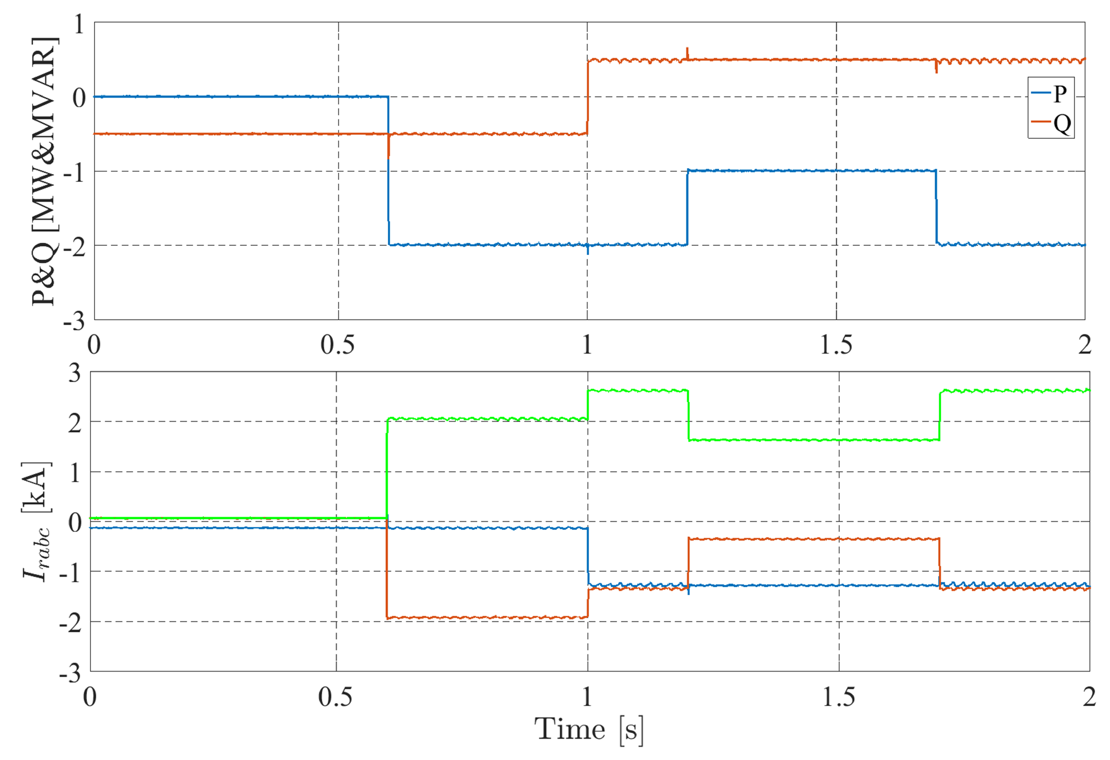
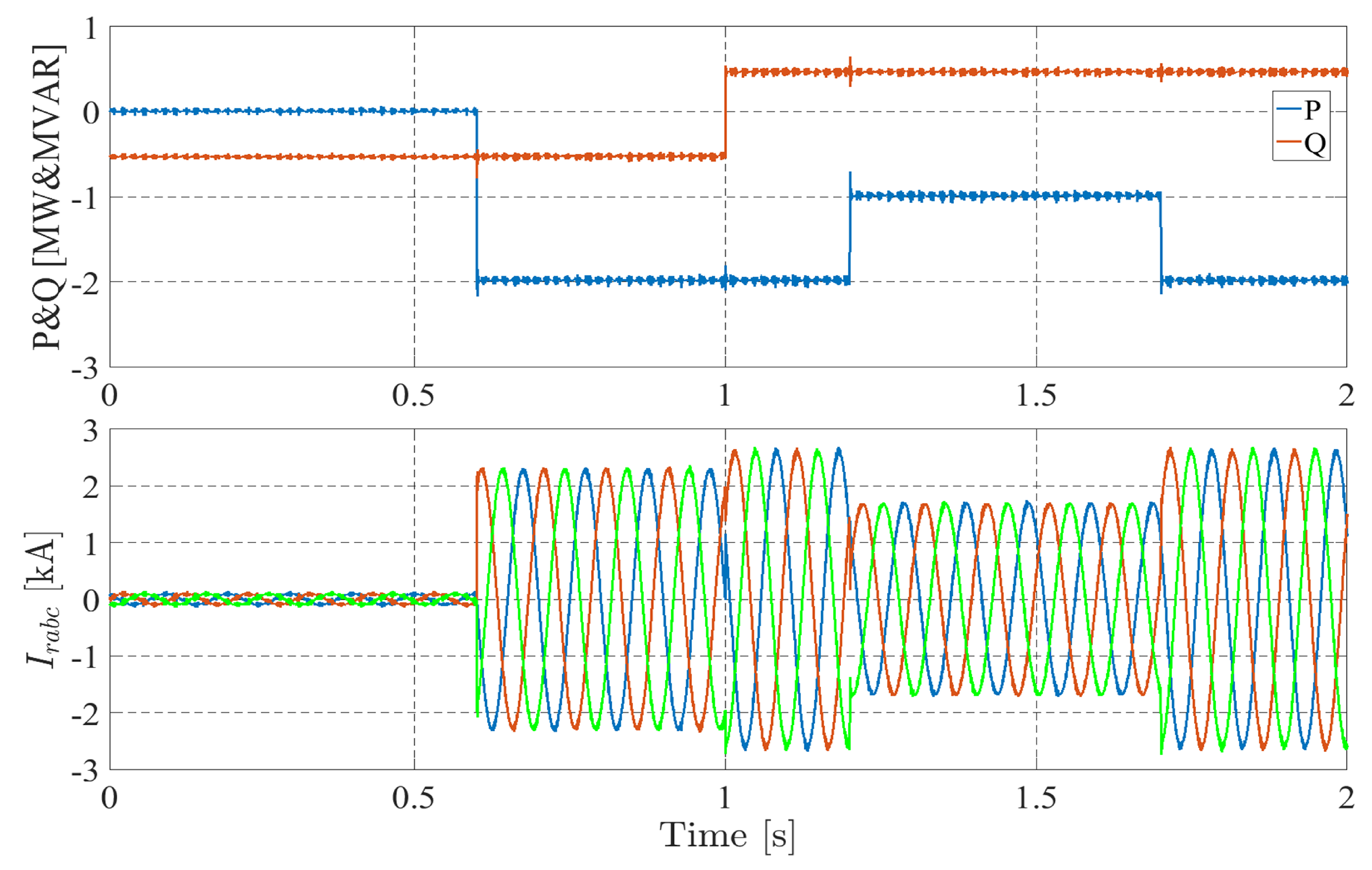
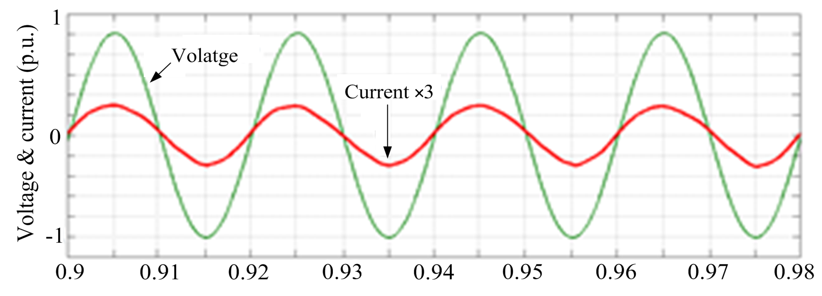
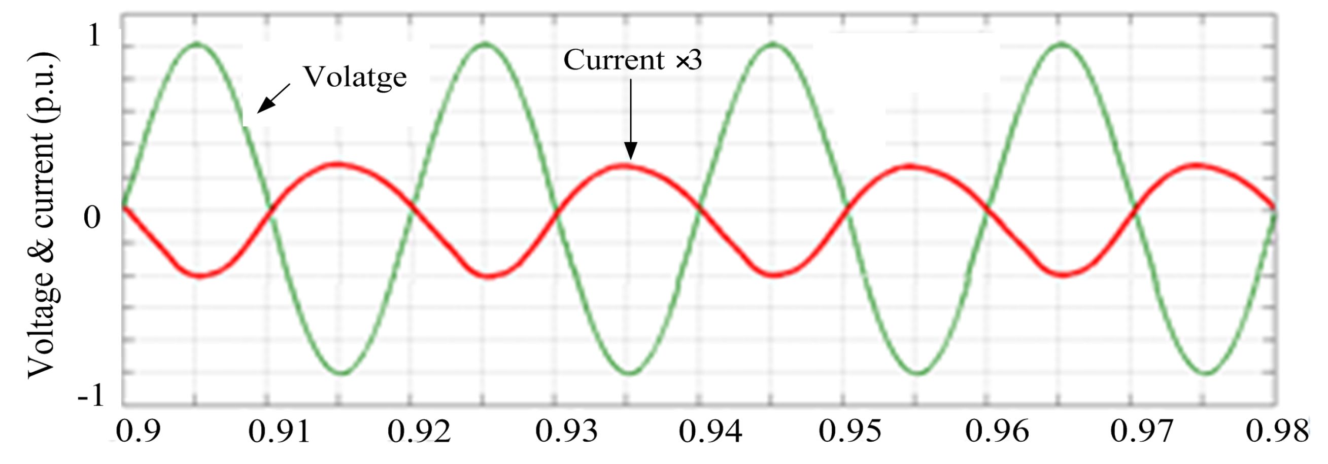
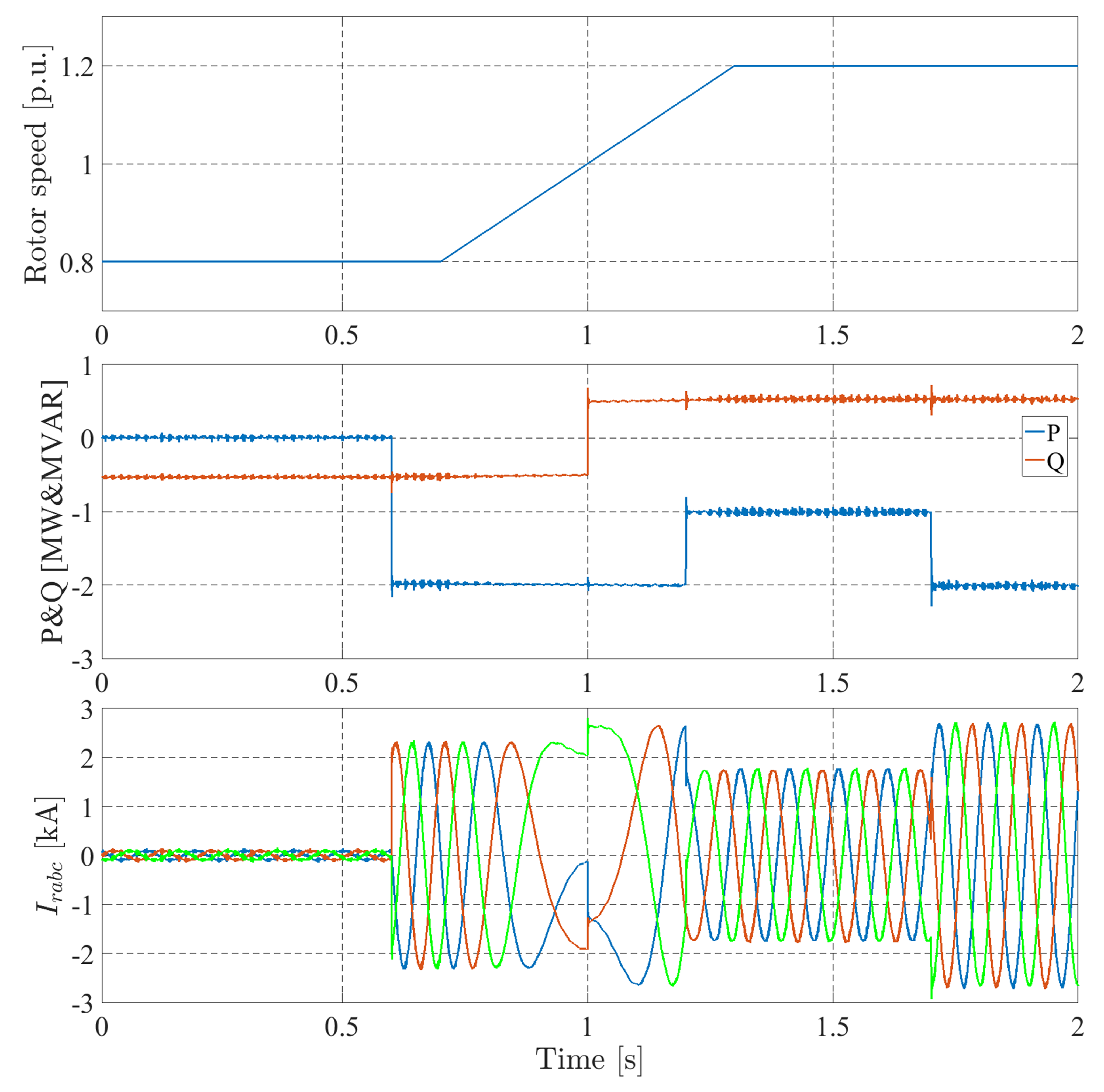
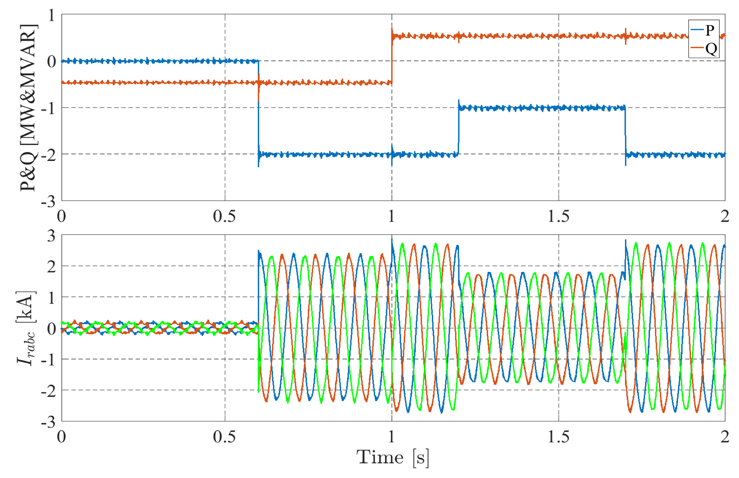
4. Simulation Results

In this section, in order to demonstrate the effectiveness of the control technique proposed in Section 3, various simulations are performed and the results are presented and analyzed. The schematic diagram of the system under test is shown in Figure 10, where RLC filter is considered to absorb the switching harmonics produced by the modulation of the matrix converter. The power of the double-fed induction generator under study is 2 MW whose specifications are tabulated in Table 2. In addition, the switching frequency and sampling frequency has been set at 5 [kHz].
Figure 11 reports the simulation results at synchronous speed, where the speed of the rotor is fixed at 1 p.u. As seen, the reactive power set point was at −0.5 [MVAR], while it goes to 0.5 [MVAR] at t = 1 [s]. On the other hand, the active power reference has a step change from zero to −2 [MW] at t = 0.6 [s] and goes to −1 [MW] at t = 1.2 [s], and again goes back to −2 [MW] at t = 1.7 [s]. It is noted that negative sign “−” implies on active power generation and reactive power absorption by DFIG. As seen from this figure, both powers follow their set points precisely. Furthermore, rotor current is shown in this figure. It is evident from the rotor current waveform that it is dc, because of setting rotor speed at synchronous speed.
The same test has been done at sub-synchronous speed, where the speed of the rotor has been set at 0.8 p.u, as illustrated in Figure 12. As seen, similar to previous tests, both powers follow their set points precisely. In addition, from the rotor current waveform, it is evident that the rotor flux rotates at 10 [Hz].
Figure 13 illustrates the input phase voltage and its corresponding filtered current of input side of MC for IP-A. As shown, the input voltage and input current are in phase thanks to the control of input power factor and hence input reactive power of MC.
Figure 14 reports the simulation results for super-synchronous speed, where the speed of the rotor is set at 1.2 p.u. Analogous to synchronous and sub-synchronous cases, both reactive and active powers follow their corresponding set points. In addition, the input phase voltage and its corresponding filtered current for IP-A of MC is depicted in Figure 15. As it is clear, similar to Figure 13, unity input power factor is achieved. However, the phase angle between voltage and current is 180 degree due to the fact that unlike the sub-synchronous case, in super-synchronous mode, the power direction is from the rotor side to the grid.
Finally, the performance of the proposed control technique in speed transients is investigated in Figure 16, where the system’s operation changes from sub-synchronous to super-synchronous mode. The simulation results indicates that in the period of 0.7 [s] to 1.3 [s] rotor speed changes from 0.8 p.u. to 1.2 p.u. As seen from the results, the system response is precise during speed transients.
As mentioned above, the advantage of the proposed method is to have a fixed switching frequency for matrix converter modulation. Figure 17 illustrates the switching frequency spectrum of MC under test. As seen, switching frequency is fixed at 5 kHz. Therefore, the filter design for the input side of MC becomes more convenient.

Comparison with Variable Switching Frequency

In this section, simulation results for direct power control of matrix converter-fed DFIG are investigated, while the active and reactive powers are controlled via hysteresis controllers. It is known that due to nature of hysteresis control, switching frequency is variable and also active and reactive power ripples are larger compared to fixed switching frequency methods. Figure 18 reports the results for active and reactive power control, where at t = 0.8 s, 2 MW active power is generated and at t = 1.4 s active power generation decreases to 1 MW. Also until t = 1.1 s, 0.5 MVAR reactive power is absorbed from the grid and after that the same amount of reactive power is injected to the grid. As seen, compared to active and reactive power control results from ISVM of MCs, the power ripples in hysteresis control are visibly larger. In addition, the switching frequency of hysteresis based controller is depicted in Figure 19. As expected, the switching frequency for this kind of power control is variable.

5. Conclusions

A direct power control of matrix converter-fed DFIG was presented in this paper, where the matrix converter is modultaed using ISVM technique. Compared to what has been done in the past for DPC of MC-fed DFIG, the switching frequency of proposed method is constant at 5 [kHz] which leads to precise filters design. Furthermore, an extensive discussion was addressed for nonlinearities of matrix converters due to commutation between input phases and on-state voltage drop. It was shown that if these nonlinear voltage errors are not compensated properly, the power regulation may be affected due to these voltage errors. The proposed method was applied on an MC-Fed DFIG, and various simulation tests have been performed to verify the advantages of matrix converters in DPC of DFIGs. To do so, three tests have been performed in synchronous, sub-synchronous, and super-synchronous speeds and in all cases, it has been demonstrated that active and reactive power regulation is precise and also unity input power factor was achieved.

Author Contributions

All authors jointly contributed to the research model and implementation, results analysis and writing of the paper.

Funding

This research received no external funding.

Conflicts of Interest

The authors declare no conflict of interest.

References

  1. Rodrigues, E.M.G.; Godina, R.; Marzband, M.; Pouresmaeil, E. Simulation and Comparison of Mathematical Models of PV Cells with Growing Levels of Complexity. Energies 2018, 11, 2902. [Google Scholar] [CrossRef]
  2. Barton, J.P.; Infield, D.G. Energy storage and its use with intermittent renewable energy. IEEE Trans. Energy Convers. 2004, 19, 441–448. [Google Scholar] [CrossRef]
  3. Lalor, G.; Mullane, A.; O’Malley, M. Frequency control and wind turbine technologies. IEEE Trans. Power Syst. 2005, 20, 1905–1913. [Google Scholar] [CrossRef]
  4. Tavakkoli, M.; Adabi, J.; Zabihi, S.; Godina, R.; Pouresmaeil, E. Reserve Allocation of Photovoltaic Systems to Improve Frequency Stability in Hybrid Power Systems. Energies 2018, 11, 2583. [Google Scholar]
  5. Muller, S.; Deicke, M.; De Doncker, R.W. Doubly fed induction generator systems for wind turbines. IEEE Ind. Appl. Mag. 2002, 143, 26–33. [Google Scholar] [CrossRef]
  6. Akagi, H.; Sato, H. Control and performance of a doubly-fed induction machine intended for a flywheel energy storage system. IEEE Trans. Power Electron. 2002, 17, 109–116. [Google Scholar] [CrossRef]
  7. Xu, L.; Cartwright, P. Direct active and reactive power control of DFIG for wind energy generation. IEEE Trans. Energy Convers. 2006, 21, 750–758. [Google Scholar] [CrossRef]
  8. Takahashi, I.; Noguchi, T. A New Quick-Response and High-Efficiency Control Strategy of an Induction Motor. IEEE Trans. Ind. Appl. 1986, IA-22, 820–827. [Google Scholar] [CrossRef]
  9. Zhi, D.; Xu, L. Direct Power Control of DFIG With Constant Switching Frequency and Improved Transient Performance. IEEE Trans. Energy Convers. 2007, 22, 110–118. [Google Scholar] [CrossRef]
  10. Zhi, D.; Xu, L.; Williams, B.W. Model-Based Predictive Direct Power Control of Doubly Fed Induction Generators. IEEE Trans. Power Electron. 2010, 25, 341–351. [Google Scholar]
  11. Sun, D.; Wang, X.; Nian, H.; Zhu, Z.Q. A Sliding-Mode Direct Power Control Strategy for DFIG under Both Balanced and Unbalanced Grid Conditions Using Extended Active Power. IEEE Trans. Power Electron. 2018, 33, 1313–1322. [Google Scholar] [CrossRef]
  12. Abad, G.; Rodriguez, M.A.; Poza, J. Two-Level VSC Based Predictive Direct Torque Control of the Doubly Fed Induction Machine With Reduced Torque and Flux Ripples at Low Constant Switching Frequency. IEEE Trans. Power Electron. 2008, 23, 1050–1061. [Google Scholar] [CrossRef]
  13. Abad, G.; Rodríguez, M.A.; Iwanski, G.; Poza, J. Direct Power Control of Doubly-Fed-Induction- Generator-Based Wind Turbines Under Unbalanced Grid Voltage. IEEE Trans. Power Electron. 2010, 25, 442–452. [Google Scholar] [CrossRef]
  14. Wheeler, P.W.; Rodriguez, J.; Clare, J.C.; Empringham, L.; Weinstein, A. Matrix converters: A technology review. IEEE Trans. Ind. Electron. 2002, 49, 276–288. [Google Scholar] [CrossRef]
  15. Huber, L.; Borojevic, D. Space vector modulated three-phase to three-phase matrix converter with input power factor correction. IEEE Trans. Ind. Appl. 1995, 31, 1234–1246. [Google Scholar] [CrossRef]
  16. Yousefi-Talouki, A.; Pellegrino, G.; Mengoni, M.; Zarri, L. Self-commissioning algorithm for matrix converter, nonlinearity compensation. In Proceedings of the 2015 IEEE Energy Conversion Congress and Exposition (ECCE), Montreal, QC, Canada, 20–24 Septemeber 2015; pp. 4077–4083. [Google Scholar]
  17. Stella, F.; Yousefi-Talouki, A.; Odhano, S.; Pellegrino, G.; Zanchetta, P. An Accurate Self-Commissioning Technique for Matrix Converters Applied to Sensorless Control of Synchronous Reluctance Motor Drives. IEEE J. Emerg. Sel. Top. Power Electron. 2018. [Google Scholar] [CrossRef]
  18. Mondal, S.; Kastha, D. Maximum Active and Reactive Power Capability of a Matrix Converter-Fed DFIG-Based Wind Energy Conversion System. IEEE J. Emerg. Sel. Top. Power Electron. 2017, 5, 1322–1333. [Google Scholar] [CrossRef]
  19. Rajendran, S.; Govindarajan, U.; Sankar, D.S.P. Active and reactive power regulation in grid connected wind energy systems with permanent magnet synchronous generator and matrix converter. IET. Power Electron. 2014, 7, 591–603. [Google Scholar] [CrossRef]
  20. Alizadeh, M.; Kojuri, S.S. Modelling, control, and stability analysis of quasi-Z-source matrix converter as the grid interface of a PMSG-WECS. IET Gener. Transm. Dis. 2017, 11, 3576–3585. [Google Scholar] [CrossRef]
  21. Cardenas, R.; Pena, R.; Tobar, G.; Clare, J.; Wheeler, P.; Asher, G. Stability Analysis of a Wind Energy Conversion System Based on a Doubly Fed Induction Generator Fed by a Matrix Converter. IEEE Trans. Ind. Electron. 2009, 56, 4194–4206. [Google Scholar] [CrossRef]
  22. Yousefi-Talouki, A.; Pouresmaeil, E.; Nørregaard Jørgensen, B. Active and reactive power ripple minimization in direct power control of matrix converter-fed DFIG. Int. J. Electr. Power Energy Syst. 2014, 63, 600–608. [Google Scholar] [CrossRef]
  23. Yousefi-Talouki, A.; Negnevitsky, M. Direct power control of matrix converter-fed doubly fed induction generator. In Proceedings of the 2013 Australasian Universities Power Engineering Conference (AUPEC), Hobart, Australia, 29 September–3 October 2013; pp. 1–6. [Google Scholar]
  24. Mondal, S.; Kastha, D. Improved Direct Torque and Reactive Power Control of a Matrix-Converter-Fed Grid-Connected Doubly Fed Induction Generator. IEEE Trans. Ind. Electron. 2015, 62, 7590–7598. [Google Scholar] [CrossRef]
  25. Akagi, H.; Kanazawa, Y.; Nabae, A. Generalized theory of the instantaneous reactive power in three-phase circuits. In Proceedings of the International Power Electronics Conference, Tokyo, Janpan, 27–31 March 1983; pp. 1375–1386. [Google Scholar]
  26. Wu, C.; Nian, H.; Zhou, Q.; Cheng, P.; Pang, B.; Sun, D. Harmonic Impedance Modeling of DFIG Considering Dead Time Effect of Rotor Side Converter. In Proceedings of the 2018 IEEE Energy Conversion Congress and Exposition (ECCE), Portland, OR, USA, 23–27 September 2018; pp. 950–955. [Google Scholar]
  27. Herran, M.A.; Fischer, J.R.; Gonzalez, S.A.; Judewicz, M.G.; Carrica, D.O. Adaptive Dead-Time Compensation for Grid-Connected PWM Inverters of Single-Stage PV Systems. IEEE Trans. Power Electron. 2013, 28, 2816–2825. [Google Scholar] [CrossRef]
  28. Lee, D.-H.; Ahn, J.-W. A Simple and Direct Dead-Time Effect Compensation Scheme in PWM-VSI. IEEE Trans. Ind. Appl. 2014, 50, 3017–3025. [Google Scholar] [CrossRef]
Figure 1. Doubly fed induction generator (DFIG) circuit in synchronous d q reference frame.
Sustainability 11 02604 g001
Figure 2. Vector diagram of rotor and stator flux linkages in synchronous frame.
Sustainability 11 02604 g002
Figure 3. Schematic diagram of direct power control of DFIG.
Sustainability 11 02604 g003
Figure 4. Matrix converter (MC) topology.
Sustainability 11 02604 g004
Figure 5. Matrix converters’ (a) output and (b) input vectors.
Sustainability 11 02604 g005
Figure 6. Fictitious voltage source rectifier (VSR) and fictitious voltage source inverter (VSI) conversions.
Sustainability 11 02604 g006
Figure 7. Four step current-based commutation (FS-CBC) from A B : (a) positive and (b) negative output current.
Sustainability 11 02604 g007
Figure 8. Fours-step current based commutation.
Sustainability 11 02604 g008
Figure 9. Input phase voltages in different input sectors.
Sustainability 11 02604 g009
Figure 10. Schematic diagram of system under investigation.
Sustainability 11 02604 g010
Figure 11. Simulation results at synchronous speed (1 p.u.); upper figure: active and reactive powers waveforms, bottom figure: rotor current waveforms.
Sustainability 11 02604 g011
Figure 12. Simulation results at sub-synchronous speed (0.8 p.u.); upper figure: active and reactive powers waveforms, bottom figure: rotor current waveforms.
Sustainability 11 02604 g012
Figure 13. Input phase voltage-A and its corresponding filtered current at sub-synchronous speed 0.8 p.u. (for the test of Figure 12).
Sustainability 11 02604 g013
Figure 14. Simulation results at super-synchronous speed (1.2 p.u.); upper figure: active and reactive powers waveforms, bottom figure: rotor current waveforms.
Sustainability 11 02604 g014
Figure 15. Input phase voltage-A and its corresponding filtered current at super-synchronous speed 1.2 p.u. (for the test of Figure 14).
Sustainability 11 02604 g015
Figure 16. Simulation results in speed transients; from top to bottom: rotor speed, active and reactive powers, and rotor current waveforms.
Sustainability 11 02604 g016
Figure 17. Switching frequency spectrum for indirect space vector modulation (ISVM) of the matrix converter under test.
Sustainability 11 02604 g017
Figure 18. Active and reactive power control of MC-fed DFIG using hysteresis direct power control (DPC).
Sustainability 11 02604 g018
Figure 19. Switching frequency for modulation of MC in hysteresis based DPC.
Sustainability 11 02604 g019
Table 1. Edge Uncertainty (EU) voltage error.
Input Sectors V EU
1 3 V A ( t c + t f / 2 t r / 2 ) T P W M · s i g n ( i i ) , i = a , b , c
2 3 V C ( t c + t f / 2 t r / 2 ) T P W M · s i g n ( i i ) , i = a , b , c
3 3 V B ( t c + t f / 2 t r / 2 ) T P W M · s i g n ( i i ) , i = a , b , c
4 3 V A ( t c + t f / 2 t r / 2 ) T P W M · s i g n ( i i ) , i = a , b , c
5 3 V C ( t c + t f / 2 t r / 2 ) T P W M · s i g n ( i i ) , i = a , b , c
6 3 V B ( t c + t f / 2 t r / 2 ) T P W M · s i g n ( i i ) , i = a , b , c
Table 2. Specifications of doubly fed induction generator (DFIG) under test.
DFIG Parameters
Rated power2 [MW]
Stator voltage690 [V]
Stator/rotor turns ratio0.3
R s 0.0108 p.u.
R r 0.0121 p.u. (referred to the stator)
L m 3.362 p.u.
L σ s 0.102 p.u.
L σ r 0.11 p.u. (referred to the stator)
Lumped inertia constant0.2 s
Number of pole pairs2
Matrix Converter Specifications
t d 1 / t c / t d 2 0.6 [ μ s]/0.46 [ μ s]/0.6 [ μ s]
Input filter inductance 1 [mH]
Input filter capacitance 12 [ μ F]

