Article

Impact of PSO Reinitialization on the Accuracy of Dynamic Global Maximum Power Detection of Variant Partially Shaded PV Systems

by
Ali M. Eltamaly
1,2,
Hassan M. H. Farh
3,* and
Mamdooh S. Al Saud
3,4
1
Sustainable Energy Technologies Center, King Saud University, Riyadh 11421, Saudi Arabia
2
Electrical Engineering Department, Mansoura University, Mansoura 35516, Egypt
3
Electrical Engineering Department, College of Engineering, King Saud University, Riyadh 11421, Saudi Arabia
4
Saudi Electricity Company Chair in Power System Reliability and Security, King Saud University, Riyadh 11421, Saudi Arabia
*
Author to whom correspondence should be addressed.
Sustainability 2019, 11(7), 2091; https://doi.org/10.3390/su11072091
Submission received: 14 February 2019 / Revised: 13 March 2019 / Accepted: 26 March 2019 / Published: 8 April 2019
(This article belongs to the Section Sustainable Engineering and Science)

Abstract

:
The Global Maximum Power (GMP) of photovoltaic (PV) systems changes its location on the power–voltage (P–V) curve as the shading pattern (SP) changes over time. Although the original Particle Swarm Optimization (PSO) technique can catch the GMP easily under the same SP, once it changes its location, it cannot catch the new GMP because the particles search around the first GMP caught. Therefore, conventional PSO is a time-invariant GMP tracker that cannot follow the dynamic GMP under variant SP. The novelty in this study is the modification of the conventional PSO technique to become a time-variant GMP technique. This has been achieved through dispersing the particles based on two new reinitialization methodologies for searching for the variant GMP. The first methodology depends on dispersing the PSO particles at a certain predefined time (PDT) in order to look for the new GMP of the new SP. The latter depends on continually monitoring any changes in the SP to disperse the particles to follow the new GMP. A detailed comparison between the improved PSO with two new reinitialization methodologies and the conventional PSO is introduced. The improved PSO with SP change reinitialization methodology tracked the dynamic GMP efficiently and accurately compared the conventional PSO and the improved PSO with PDT reinitialization. Also, no hardware modification in the existing PV system is required, which makes it an excellent option to improve the performance of new and existing PV systems.

1. Introduction

In recent years, renewable energy systems have attracted the attention of the world, especially solar energy systems, because there is no pollution, less maintenance, and it has many other benefits compared to conventional sources of energy. With recent advances, the generated energy cost has become lower and the photovoltaic (PV) array efficiency has improved through tracking the maximum power, which is the main focus of this study. Doubtless, increasing the generated energy from PV systems will reduce the cost of energy and improve the system performance considerably. This can be achieved by imposing modern, effective, and smart maximum power point tracking (MPPT) techniques to the PV energy systems [1,2,3].
Under uniform radiations, power–voltage (P–V) characteristics contain a unique peak and conventional MPPT techniques are efficient in tracking this unique peak [3,4,5]. P–V characteristics contain multiple maximum power peaks; unique Global Maximum Power (GMP) and many Local Maximum Powers (LMPs) under partial shading conditions (PSCs), which cannot be tracked by conventional MPPT techniques [1,6,7]. As a result, numerous modern, efficient, and accurate bio-inspired MPPT techniques are proposed to track the GMP instead of LMPs. For example, Jubaer et al. [8] discovered that both the Cuckoo Search Optimization (CSO) and Particle Swarm Optimization (PSO) are efficient to catch the GMP under PSC but CSO has good performance compared to PSO in both GMP convergence and tracking speed. The PSO modifications implemented in [9,10] improved the PSO performance to be in the same ranking with the Firefly Algorithm (FA) and CSO in terms of GMP convergence and tracking speed. Fathy et al. [11] proposed a modified Ant Bee Colony (ABC) to alleviate the partial shading effect and proved that a modified ABC has the best performance in tracking the global maximum power compared to GA, PSO, and ABC. Finally, Prasanth et al. [12] proved the superior performance of the Flower Pollination Algorithm (FPA) in GMP tracking in terms of GMP convergence and tracking speed compared to PSO and P&O.
In the case of shading pattern (SP) changes, the GMP will change its value and position. The MPPT technique should be able to catch the GMP with time variation. Many research papers [5,8,9,10,11,12,13,14,15,16,17,18] supposed that the PSO technique can catch the GMP in general. PSO can catch the GMP under a certain SP and all particles will be concentrated at this GMP’s position. It can be said that conventional PSO cannot follow the new GMP when its value and region change under time-variant SP of the PV system. All these studies [5,8,9,10,11,12,13,14,15,16,17,18] did not point out to the problem of changing the GMP position with time and the performance of PSO particles in case of time-variant GMP. Conventional PSO can track the GMP under time-invariant partial shading patterns efficiently and accurately. Once the GMP changes due to time-variant SP; PSO sticks to the first GMP and becomes unable to catch the dynamic GMP under time-variant partial shading patterns without certain initialization or particle dispersion. Therefore, modifications related to the reinitialization or dispersing of the PSO particles are compulsory to deal with time-variant partial shading patterns and to track the time-variant GMP. PSO reinitialization means that the PSO particles are dispersed as a consequence of the SP change; thus, they are able to search for the new GMP of the new SP condition. On the other hand, numerous research papers [9,12,19,20,21,22,23,24,25] have modified PSO and some MPPT techniques based on bio-inspired techniques such as FPA, FA, and ABC to extract the variant GMP under variant partial shading patterns. Different methodologies are introduced to detect whether the SP or radiation is changed or not. Ram and Rajasekar [9,12] detected the SP and radiation changes by checking the PV output voltage and current variation. Jiang et al. [19] detected radiation change by checking the PV current change between two subsequence iterations [19]. In addition, other studies [20,21,22,23] considered that the radiation is changed if the PV output power is changed. Also, Sundareswaran et al. [24] detected the radiation change based on the two previous conditions mentioned in [9,12] and [20,21,22,23] to reinitialize the PSO or ABC to track the variant GMP efficiently. Also, Mirhassan et al. in [25] detected radiation change based on two conditions together; first, the change between current duty cycle and the GMP of PSO, when the global best position (Gbest) is less than the minimum duty ratio change, ΔDmin; and second, the variation between the current and global power is greater than (PGMP* ΔP); where PGMP is the global maximum power and ΔP is the power change. These detection methodologies [9,12,16,19,20,21,22,23,24,25] do not guarantee that the SP has changed. It may happen due to load or/and normal radiation changes even without changes in SP. In addition, although the radiation may change, the searching region may not; hence, there is no need for PSO reinitialization, which may cause undesirable disturbances in the PV system.
To date, this problem has not been solved, but it will be solved in this paper, which proposes two new methodologies to disperse the PSO particles to follow the variant GMP under variant SP. The two modified methodologies for initialization of the PSO depend on predefined time and detection of SP changes. A detailed description, simulation, and comparison between these two modified methodologies and the state of the art methodology [5,8,9,10,11,12,13,14,15,16,17,18] that uses conventional PSO without dispersing particles will be introduced, discussed, and analyzed. The conventional PSO technique is a time-invariant optimization technique. Therefore, it cannot track the dynamic GMP under a time-variant shading pattern. To the best of our knowledge, this study is the first to discuss the PSO with dispersion of the particles to catch variant GMP power under variant partial shading patterns. The new contribution of this paper is the improvement of the conventional PSO to become a time-variant GMP technique. This has been achieved through proposing two modified reinitialization methodologies for searching for the variant GMP. The first methodology is done by dispersing the particles every so often in order to look for the new GMP. The second one is by continually monitoring any change in the shading pattern to disperse the PSO particles. A detailed comparison between the improved PSO with these two reinitialization methodologies and the conventional PSO technique without reinitialization is presented.
This paper is structured as follows; Section 2 demonstrates the PV energy system modelling. Section 3 and Section 4 introduce the GMP tracking based on the improved PSO technique with two proposed methodologies of dispersing the particles. Section 5 discusses and analyzes the simulations. Finally, Section 6 provides conclusions.

2. Description of the Partially Shaded Photovoltaic System

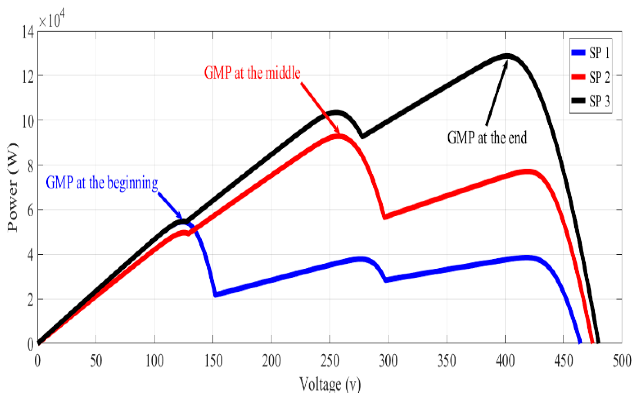
Figure 1 presents a PV energy system where the PV array is interfaced with the utility system via a DC–DC converter (boost) and three-phase inverter. The inputs to the PV array are irradiance (W/m2) and temperature (°C). Three PV arrays with three different irradiances are used for representing the time-variant PSCs. As a result of PSCs, multiple maximum power peaks are generated for each shading pattern; here, the three maximum power points are one GMP and two LMPs; and the occurrence of the GMP at different places of the P–V curve is achieved under time-variant radiation or SPs. The variant irradiance will make the GMP change its position along with the voltage. Three different partial shading patterns are applied continuously with three different GMP positions and values (GMP locates 1st, GMP locates 2nd, GMP locates 3rd) as shown in Figure 2. Time-variant irradiances are used to generate GMPs at different positions to see the PSO response to follow the GMP if it changes its position with and without initialization (particle dispersion). As shown in Figure 1, Matlab/Simulink includes the PV energy system under variant partial shading; the improved PSO algorithm is in M-file. The improved PSO gets the PV voltage, current, and power at each duty cycle sent to the converter in Simulink.

3. Global Peak Extraction Using Particle Swarm Optimization Technique

The PSO-based MPPT technique is considered one of the superior bio-based MPPT techniques. It can extract the GMP power under the same partial shading pattern efficiently [5,8,9,10,11,12,13,14,15,16,17,18]. However, it cannot extract the variant GMP under variant partial shading patterns without reinitialization of the PSO search process [9,12,19,20,21,22,23,24,25]. Tracking the GMP under the same SP relies on the updating of the particle’s velocity and position [10,26,27,28], but it needs to disperse the agents or particles to track the variant GMP, as will be discussed in this paper. Each particle has two main vectors; the position and velocity; xik and vik, respectively. The particle’s new position can be estimated as follows [10]:
x i k + 1 = x i k + v i k + 1
where, i is the particle number and k is the iteration number.
To estimate the particle’s new position, the particle’s velocity is calculated using the inertia weight; ω, the particle’s current position; xik, the particle’s velocity vik, the acceleration coefficients (c1 and c2), the random numbers (r1, r2), and the personal and global best position (Pbest i and Gbest) as follows:
v i k + 1 = ω v i k + c 1 r 1 ( P b e s t   i x i k ) + c 2 r 2 ( G b e s t x i k )
Some researches [10,27,29] modified the conventional PSO to improve the output response around the GMP and the tracking speed. For example, a deterministic particle swarm optimization (DPSO) was proposed [27] to upgrade the tracking ability and tracking speed of the conventional PSO through removing the random numbers in the previous equation as follows [27]:
v i k + 1 = ω   v i k + ( P b e s t   i x i k ) + ( G b e s t x i k )
v i k + 1 = ω   v i k + ( P b e s t   i + G b e s t 2 x i k )
Based on Equation (2) after removing the random numbers (r1 and r2) and retaining the accelerating factors, the velocity of the particle can be estimated as follows:
v i k + 1 = ω v i k + c 1 P b e s t   i + c 2 G b e s t c 3 x i k

4. Proposed Particle Swarm Optimization Techniques

4.1. State of the Art PSO Methodology without Reinitialization (Case-1)

In this case, the PSO initialization is executed once at the beginning. Therefore, PSO will track the first GMP and the particles will be fastened around the first GMP region. Once the partial shading pattern changes, the GMP may change its value and position and the particles will not see the new GMP due to their position around the previous GMP. The algorithm logic sequence is as follows [1]:
Step 1:
Initialize the PSO parameters (ω, c1, c2, and c3) and send the initial duty cycles sequentially to the partially shaded PV system (objective function) and gather the associated powers values.
Step 2:
Update the particles’ position and velocity ( x i k + 1 and v i k + 1 ) using Equations (1) and (5), respectively, then obtain the new duty cycles values of the converter.
Step 3:
Send new duty cycles (particles’ position) to the partially shaded PV system and gather the associated powers values.
Step 4:
Assess Pbest,i, Gbest and their related particles’ positions, then; go back to Step 2.

4.2. Improved PSO Reinitialization upon Predefined Time (Case-2)

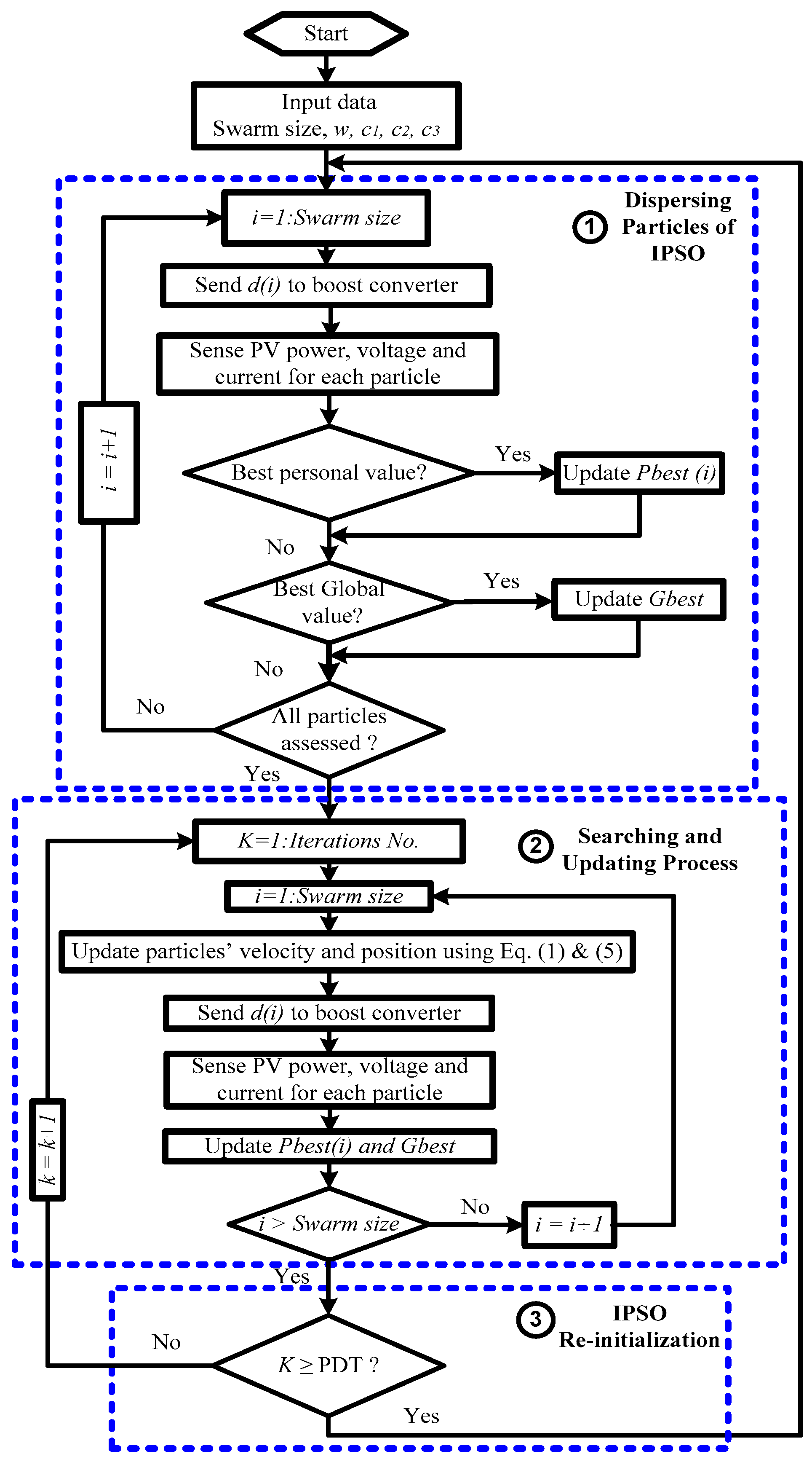
Due to the variation of SP, the GMP value and position may be changed and the particles will not catch the new GMP. For this reason, the first proposed methodology has been done by dispersing the improved PSO particles (reinitialization) after a predefined time (PDT) to let the particles look for the new GMP power in the whole searching space. The PDT for reinitialization can be selected based on the partial shading occurrence frequency in the installation site. In this paper, the PDT is set to be 24 s, where the PDT has 100 iterations and each iteration takes 0.24 s. The flowchart of the improved PSO initialization based on PDT is shown in Figure 3 and the algorithm’s logic sequence is as follows:
Step 1:
Initialize the improved PSO parameters (ω, c1, c2, and c3), send the initial duty cycles sequentially to the partially shaded PV system (objective function), and gather the associated powers values.
Step 2:
Step 2: Update the particles’ position and velocity ( x i k + 1 and v i k + 1 ) using Equations (1) and (5), respectively, then obtain the new duty cycles values of the converter.
Step 3:
Send the new duty cycles (particles’ position) to the partially shaded PV system and gather the associated powers values.
Step 4:
Assess Pbest,i, Gbest and their related particle’s position, then check if the time is less than PDT (iteration < 100), go back to Step 2 otherwise go to Step 1.

4.3. Improved PSO Reinitialization upon Shading Pattern Change (Case-3)

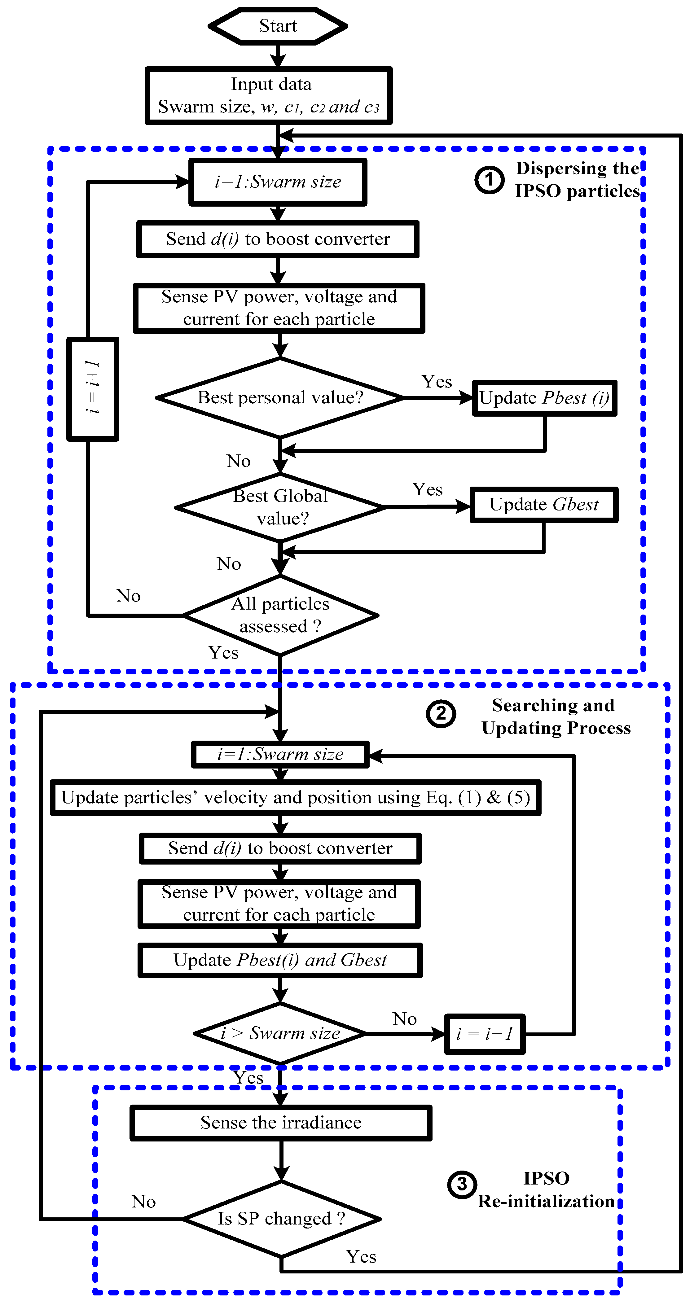
The second proposed reinitialization methodology for tracking the variant GMP has been done by checking the partial shading pattern variations. If the partial shading pattern changes, the methodology will initialize the improved PSO parameters, otherwise it will continue looking for GMP near the current peak. This technique is better than the previous one in terms of the generated energy captured because it will not randomly initialize the duty ratio. However, the main problem of this technique is the need for sensors to detect the variation of radiation. The improved PSO initialization flowchart based on partial shading pattern change is shown in Figure 4 and the algorithm’s logic sequence is as follows:
Step 1:
Initialize the improved PSO parameters (ω, c1, c2, and c3), send the initial duty cycles sequentially to the partially shaded PV system (objective function), and gather the associated powers values.
Step 2:
Update the particles’ position and velocity ( x i k + 1 and v i k + 1 ) using Equations (1) and (5), respectively, then obtain the new duty cycles values of the DC–DC converter.
Step 3:
Send the new duty cycles (particles’ position) to the partially shaded PV system and gather the associated powers values.
Step 4:
Assess Pbest,i, Gbest and their related particle’s position, then check if the SP of the PV system is not changed, go again to Step 2 otherwise go to Step 1.
The condition for checking if the SP changed to disperse the particles is shown as follows:
| I r n e w I r o l d I r o l d | ε
where, Irnew and Irold are the average irradiance for the new and previous iteration, respectively. ε is the irradiance change limit that has been assumed as 5%.

5. Simulation Results and Discussion

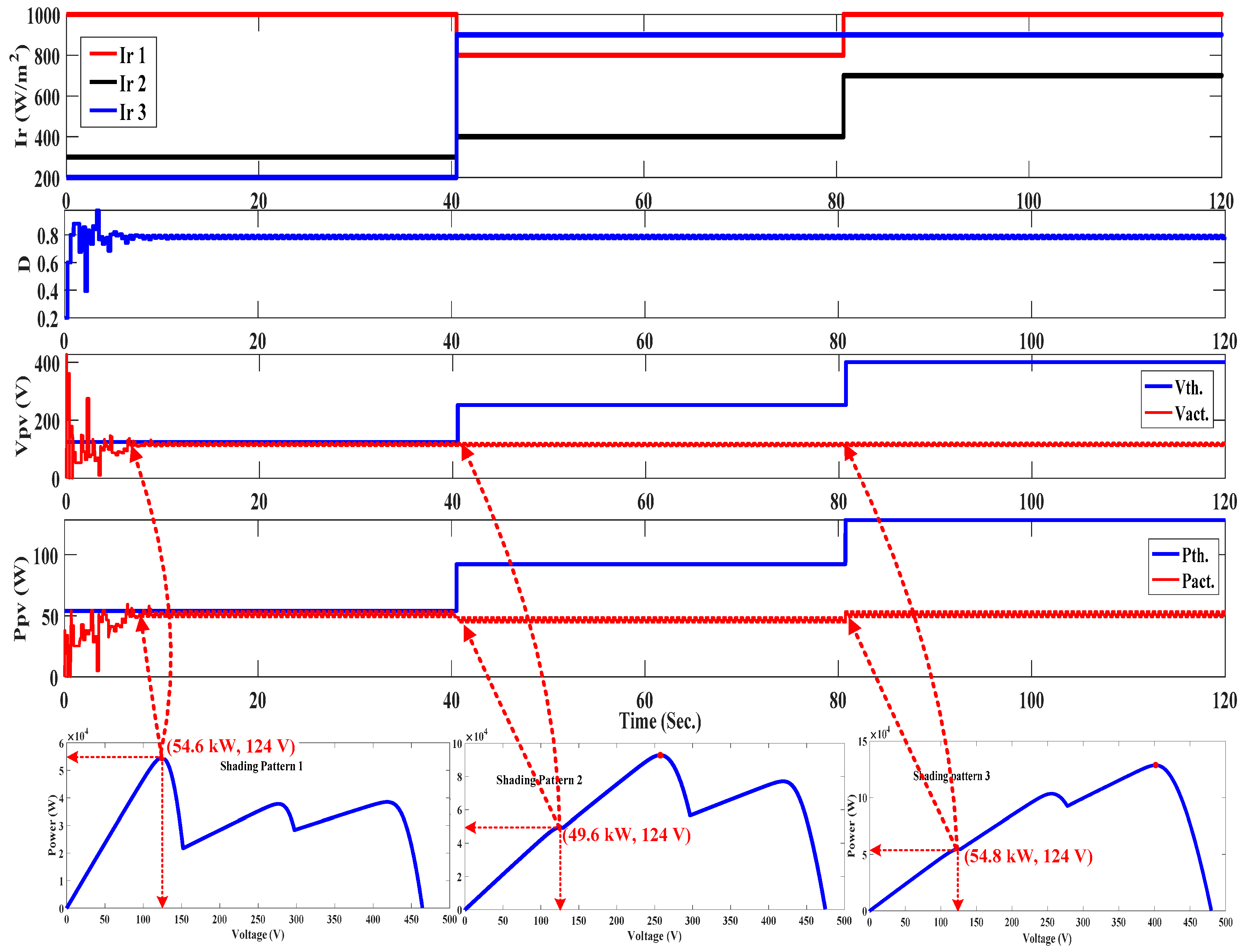
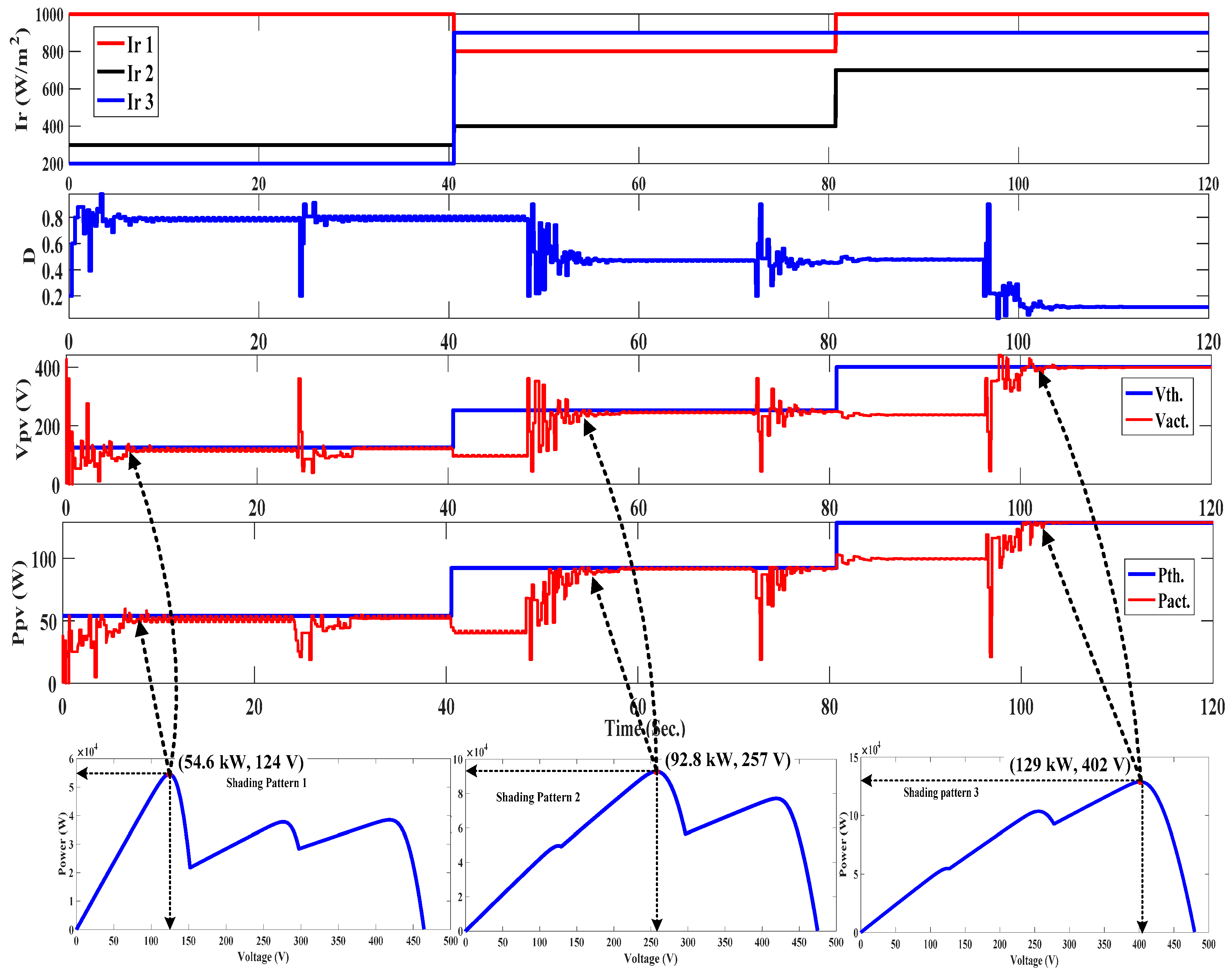
To show the effective performance obtained through the proposed improved PSO technique, numerical simulations have been implemented. Simulink contains the PV array with three different radiations interfaced to the grid via a boost converter and 3-phase inverter, while the M-file contains the improved PSO algorithm. Time-variant radiations will cause the GMP to change in time. Three time-variant SPs are applied continuously as shown in Figure 5. The purpose of this arrangement is to ensure that the GMP will occur at different positions of the P–V characteristic (GMP locates 1st, GMP locates 2nd, GMP locates 3rd), as shown in Figure 5, to analyze and evaluate the proposed improved PSO performance in time-variant SPs. The three different SPs are applied to the simulation program, wherein SP1 is applied for the first 40 s, followed by SP2 for the next 40 s, and SP3 for the last 40 s, resulting in a total simulation time of about 120 s. In this study, the time-variant irradiances are selected to simulate the occurrence of dynamic GMP and to prove that the conventional PSO will not follow the variant GMP unless the improved PSO disperses the particles by the two new proposed methodologies. A detailed comparison between these two new and efficient methodologies with dispersing the agents or particles and the conventional PSO methodology without dispersing the agents is introduced in the following sections:

5.1. Conventional PSO without Reinitialization (Case-1)

The conventional PSO initialization is carried out one time only at the beginning and the output response of the new proposed system with time is discussed as follows:
  • From 0–40 s: PSO searches for the first GMP in a certain searching area and succeeds in catching the first GMP power (54.6 kW) for SP1 as illustrated in Figure 5.
  • From 40–80 s: The partial shading pattern changed to SP2; hence, the GMP value (92.8 kW) and position (2nd GMP peak) also changed. Nevertheless, PSO cannot catch the new GMP power and remains in the first GMP searching area and its Gbest (d = 0.785). Therefore, it tracks the nearest peak in the same region of the first GMP (LMP equals to 49.6 kW); however, the current GMP is 92.8 kW for SP2. The reason is that the PSO reinitialization is not executed upon the SP change.
  • From 80–120 s: In a similar manner, the partial shading pattern is changed (SP3); hence, the GMP value (128.8 kW) and position (3rd GMP peak) also changes. Nevertheless, PSO cannot catch the new GMP and remains in the first GMP searching area and its Gbest (d = 0.785). Therefore, it tracks the nearest peak at the same region of the first GMP (LMP equals to 54.8 kW); however, the current GMP is 128.8 kW for SP3. The reason is that the PSO reinitialization is not executed upon the SP change.
Therefore, PSO reinitialization must be carried out to disperse the PSO particles to look for GMP throughout the searching space. If reinitialization of PSO has not been carried out, the PSO particles will stick to the first GMP. Therefore, the PV system will stick to the duty ratio of the first GMP and generates output power that is not GMP, but the value that corresponds to the duty ratio of the first GMP. As a result, PSO reinitialization must be carried out based on one of the two new methodologies.

5.2. Improved PSO Reinitialization Based on Predefined Time (Case-2)

As discussed in the simulation results of Case-1, the particles remain in the first GMP searching region and if the SP changes, the particles cannot catch the new GMP. With the PDT for improved PSO reinitialization (Case-2), the improved PSO is initialized every PDT (24 s) to look for the new GMP. The output response of the new proposed system versus time is shown as follows:
  • From 0–24 s: The improved PSO caught the first GMP power (54.6 kW and 124 V) for SP1 as presented in Figure 6.
  • From 24–40 s: The improved PSO reinitialization is executed, but the partial shading pattern has not changed; therefore, the system works again after reinitialization at the same situation (54.6 kW and 124 V). This reinitialization methodology has unwanted reinitialization that may disturb the PV system. Therefore, the reinitialization methodology upon PDT is no better in partial shading conditions.
  • From 40–48 s: The partial shading pattern changes to SP2; hence, the GMP value and position also changes, but the improved PSO will not catch it until improved PSO reinitialization is executed. It remains at the nearest peak in the same region of the first GMP (LMP equals to 49.6 kW) until the improved PSO initialization is executed. This reinitialization has a delayed response to follow the new GMP of the new SP. Therefore, the reinitialization methodology upon PDT is no better in partial shading conditions.
  • From 48–72 s: The particles are dispersed at the beginning of this period and the particles will catch the new GMP power (92.8 kW and 257 V) at d = 0.43.
  • From 72–80 s: The improved PSO is reinitialized at the beginning of this period, but the SP has not changed; hence, the system will go again to the previous GMP point (92.8 kW and 257 V). Unwanted reinitialization occurs, which may disturb the PV system. Therefore, the reinitialization methodology upon PDT is no better in partial shading conditions.
  • From 80–96 s: The partial shading pattern changes (SP3); hence, the GMP value and position also changes, but the improved PSO will not catch it until the improved PSO reinitialization is executed. It remains at the nearest peak in the same region of the second GMP (LMP equals to 100 kW) until PSO reinitialization is executed. A delayed response occurs in order to follow the new GMP of the new SP. Therefore, the reinitialization methodology upon PDT is no better in partial shading conditions.
  • From 96 to 120 s: The improved PSO is reinitialized at the beginning of this period and the particles find the new GMP (129 kW at 402 V) for SP3.
Improved PSO reinitialization upon PDT will save in sensor cost. In addition, it has high performance and the PV system efficiency is improved compared to the PSO technique without reinitialization. The question here is whether the time interval between reinitialization is should be short or long. PSO reinitialization in short intervals will increase the disturbance, thus decreasing the power output unnecessarily. On the other hand, long intervals between reinitialization can cause the improved PSO to miss atmospheric variation and remain at the initial GMP, as shown in Figure 6. This inaccurate response to radiation change causes high power loss. Finally, dispersing the particles upon PDT depends on the frequency change of the partial shading pattern at the installation site.

5.3. Improved PSO Reinitialization Upon the SP Change (Case-3)

As discussed in Case-1, conventional PSO cannot catch dynamic GMP under variant partial shading patterns. In Case-2, a new methodology is proposed to reinitialize the PSO to look for a new GMP at certain PDT. This technique is simple, and may cause unnecessary re-initialization or it may stay unchanged for less than the PDT when the partial shading pattern changes and the PSO cannot find the new GMP until reinitialization is executed. In the second new initialization methodology (Case-3), the radiation sensors obtain their values and send it to the control system to check whether the partial shading pattern has changed or not. In the case when the partial shading pattern changes, the system will order reinitialization to look for the new position of the GMP. This new method avoids the two drawbacks of the previous technique, but it will increase the system’s cost due to the need for radiation sensors. The output response of the new proposed system with time is shown as follows:
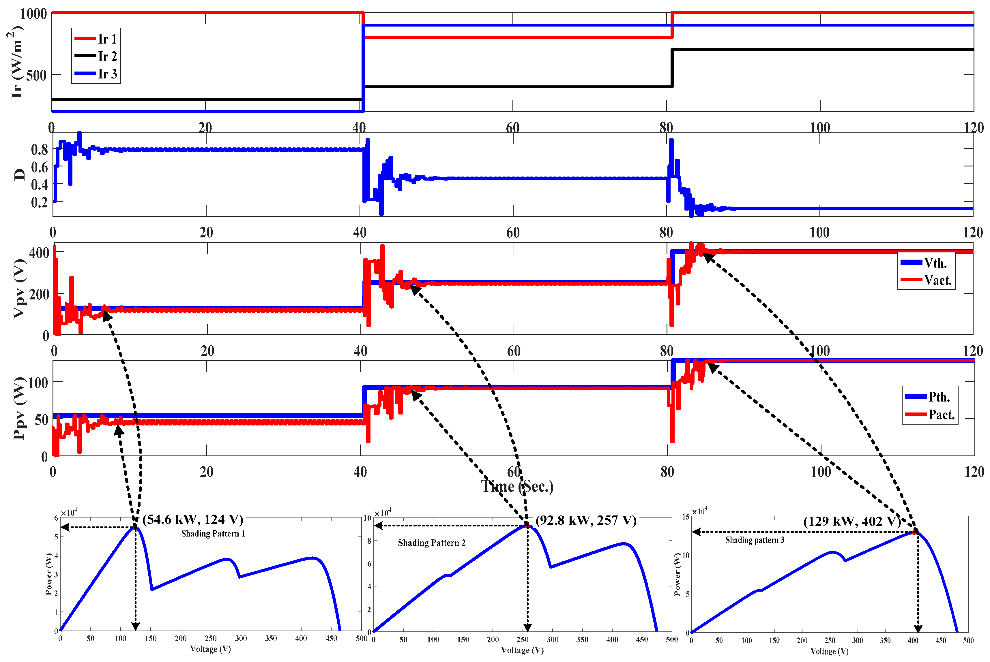
  • From 0–40 s: Improved PSO has successfully caught the first GMP power (54.6 kW and 124 V) for SP1 as shown in Figure 7.
  • From 40–80 s: The partial shading pattern changed to SP2, both the GMP value (92.8 kW) and its position also changed (2nd GMP peak). PSO reinitialization is executed upon the SP change at t = 40 s. Improved PSO succeeded in finding the second GMP peak (92.8 kW) efficiently and accurately as shown in Figure 7.
  • From 80–120 s: In a similar manner, the partial shading pattern changed to SP3. Reinitialization is executed upon the partial shading pattern change at t = 80 s. The improved PSO succeeded in finding the third GMP peak (128.8 kW) efficiently and accurately, as shown in Figure 7. The performance efficiency for this PV system is 100%, which reflects the effective performance of improved PSO reinitialization upon the partial shading pattern change. This reinitialization methodology solved the two shortcomings of the previous reinitialization methodology (PDT); unwanted reinitialization and delayed response.
Table 1 compares the improved PSO using the two proposed reinitialization methodologies with the conventional PSO in terms of dynamic global peak tracking and MPPT efficiency. For SP#2, the generated power almost doubled from 49.6 kW to 92.8 kW and efficiency increased from 53% to 100%. Moreover, for SP#3, the generated power more than doubled from 54.8 kW to 128.8 kW and its efficiency increased from 43% to 100%. These improvements can be deduced easily from the Figure 5, Figure 6 and Figure 7. These results prove that the improved PSO has superior performance compared to the conventional PSO without reinitialization in terms of dynamic global peak tracking, accuracy, and efficiency. On the other hand, PSO reinitialization based on partial shading pattern change represents the best methodology extract the variant GMP quickly and accurately.

6. Conclusions

Conventional PSO based on the MPPT technique can track the global maximum power under time-invariant partial shading patterns efficiently and accurately. Once the radiation or partial shading pattern changes, the value and position of GMP changes, whereas PSO sticks to the first GMP and cannot find the new GMP peak. This means that the conventional PSO is a time-invariant optimization technique. Therefore, certain improvements of PSO are required to deal with variant partial shading patterns and to track the variant GMP. This target has been achieved by dispersing the conventional PSO particles using two new and efficient methodologies for finding the new time-variant GMP of PV energy systems. The first methodology of dispersing the improved PSO particles is proposed based on predefined time. The second methodology of dispersing the particles is based on partial shading pattern change. Although both these new reinitialization methodologies proved superior in terms of dynamic GMP tracking, the second methodology— improved PSO with SP change reinitialization—shows higher generated power captured and efficiency than the first one. The improved PSO with PDT reinitialization suffers from two main shortcomings; unwanted reinitialization and delayed response. Although the improved PSO with reinitialization is able to track time-variant GMP, it still has undesirable oscillation at GMP (steady state). Therefore, it is recommended to hybridize it with another conventional or artificial intelligence technique to solve this dilemma.

Author Contributions

Conceptualization, A.M.E. and H.M.H.F.; Data curation, A.M.E. and H.M.H.F.; Formal analysis, A.M.E., H.M.H.F. and M.S.A.S.; Funding acquisition, A.M.E.; Investigation, A.M.E. and H.M.H.F.; Methodology, A.M.E. and H.M.H.F.; Project administration, A.M.E.; Software, A.M.E. and H.M.H.F.; Supervision, A.M.E.; Writing—original draft, H.M.H.F.; Writing—review & editing, A.M.E., H.M.H.F. and M.S.A.S.

Funding

The authors extend their appreciation to the Deanship of Scientific Research at King Saud University, Riyadh, Saudi Arabia for funding this work through research group No (RG-1439-66).

Acknowledgments

The authors extend their appreciation to the Deanship of Scientific Research at King Saud University, Riyadh, Saudi Arabia for funding this work through research group No (RG-1439-66).

Conflicts of Interest

The authors declare no conflict of interest.

Nomenclature

GMPGlobal maximum power;
PVPhotovoltaic;
SPShading Pattern;
PSOParticle swarm optimization;
PSCPartial shading condition
Pbest,iPersonal best solution;
GbestGlobal best of Pbest,i;
xikPosition vector;
vikVelocity vector;
ωInertia weight;
c1 and c2Acceleration coefficients;
r1, r2Random numbers;
MPPTMaximum Power Point Tracker;
FPAFlower pollination algorithm;
FAFirefly algorithm;
CSOCuckoo search optimization;
ABCAnt bee colony;

References

  1. Farh, H.; Othman, F.; Eltamaly, A.M.; Al-Saud, M. Maximum Power Extraction from a Partially Shaded PV System Using an Interleaved Boost Converter. Energies 2018, 11, 2543. [Google Scholar] [CrossRef]
  2. Farh, H.M.; Othman, M.F.; Eltamaly, A.M. Maximum power extraction from grid-connected PV system. In Proceedings of the 2017 Saudi Arabia Smart Grid (SASG), Jeddah, Saudi Arabia, 12–14 December 2017. [Google Scholar]
  3. Eltamaly, A.M.; Farh, H.M.; Othman, M.F. A novel evaluation index for the photovoltaic maximum power point tracker techniques. Sol. Energy 2018, 174, 940–956. [Google Scholar] [CrossRef]
  4. Rezk, H.; Eltamaly, A.M. A comprehensive comparison of different MPPT techniques for photovoltaic systems. Sol. Energy 2015, 112, 1–11. [Google Scholar] [CrossRef]
  5. Eltamaly, A.M. Performance of smart maximum power point tracker under partial shading conditions of photovoltaic systems. J. Renew. Sustain. Energy 2015, 7, 043141. [Google Scholar]
  6. Teo, J.; Tan, R.H.G.; Mok, V.H.; Ramachandaramurthy, V. Impact of Partial Shading on the PV Characteristics and the Maximum Power of a Photovoltaic String. Energies 2018, 11, 1860. [Google Scholar] [CrossRef]
  7. Eltamaly, A.M.; Farh, H.M. Dynamic global maximum power point tracking of the PV systems under variant partial shading using hybrid GWO-FLC. Sol. Energy 2019, 177, 306–316. [Google Scholar]
  8. Ahmed, J.; Salam, Z. A Maximum Power Point Tracking (MPPT) for PV system using Cuckoo Search with partial shading capability. Appl. Energy 2014, 119, 118–130. [Google Scholar] [CrossRef]
  9. Ram, J.P.; Rajasekar, N. A new robust, mutated and fast tracking LPSO method for solar PV maximum power point tracking under partial shaded conditions. Appl. Energy 2017, 201, 45–59. [Google Scholar]
  10. Ishaque, K.; Salam, Z.; Amjad, M.; Mekhilef, S. An improved particle swarm optimization (PSO)–based MPPT for PV with reduced steady-state oscillation. IEEE Trans. Power Electron. 2012, 27, 3627–3638. [Google Scholar] [CrossRef]
  11. Fathy, A. Reliable and efficient approach for mitigating the shading effect on photovoltaic module based on Modified Artificial Bee Colony algorithm. Renew. Energy 2015, 81, 78–88. [Google Scholar] [CrossRef]
  12. Ram, J.P.; Rajasekar, N. A new global maximum power point tracking technique for solar photovoltaic (PV) system under partial shading conditions (PSC). Energy 2017, 118, 512–525. [Google Scholar]
  13. Chao, K.-H.; Lin, Y.-S.; Lai, U.-D. Improved particle swarm optimization for maximum power point tracking in photovoltaic module arrays. Appl. Energy 2015, 158, 609–618. [Google Scholar] [CrossRef]
  14. Rajasekar, N.; Vysakh, M.; Vilas, H.; Mohammed, T.S.; Muralidhar, A.K.; Paul, D.; Jacob, B.; Balasubramanian, K.; Babu, T.S. Application of modified particle swarm optimization for maximum power point tracking under partial shading condition. Energy Procedia 2014, 61, 2633–2639. [Google Scholar] [CrossRef]
  15. Babu, T.S.; Rajasekar, N.; Sangeetha, K. Modified particle swarm optimization technique based maximum power point tracking for uniform and under partial shading condition. Appl. Soft Comput. 2015, 34, 613–624. [Google Scholar] [CrossRef]
  16. Dileep, G.; Singh, S. An improved particle swarm optimization based maximum power point tracking algorithm for PV system operating under partial shading conditions. Sol. Energy 2017, 158, 1006–1015. [Google Scholar] [CrossRef]
  17. Chang, L.-Y.; Chung, N.-Y.; Chao, K.-H.; Kao, J.-J. Smart Global Maximum Power Point Tracking Controller of Photovoltaic Module Arrays. Energies 2018, 11, 567. [Google Scholar] [CrossRef]
  18. Ishaque, K.; Salam, Z.; Shamsudin, A.; Amjad, M. A direct control based maximum power point tracking method for photovoltaic system under partial shading conditions using particle swarm optimization algorithm. Appl. Energy 2012, 99, 414–422. [Google Scholar] [CrossRef]
  19. Jiang, L.L.; Maskell, D.L.; Patra, J.C. A novel ant colony optimization-based maximum power point tracking for photovoltaic systems under partially shaded conditions. Energy Build. 2013, 58, 227–236. [Google Scholar] [CrossRef]
  20. Sundareswaran, K.; Peddapati, S.; Palani, S. MPPT of PV systems under partial shaded conditions through a colony of flashing fireflies. IEEE Trans. Energy Convers. 2014, 29, 463–472. [Google Scholar]
  21. Liu, Y.-H.; Salam, Z.; Shamsudin, A.; Amjad, M. A particle swarm optimization-based maximum power point tracking algorithm for PV systems operating under partially shaded conditions. IEEE Trans. Energy Convers. 2012, 27, 1027–1035. [Google Scholar] [CrossRef]
  22. Soufyane Benyoucef, A.; Chouder, A.; Kar, K.; Silvestre, S.; Aitsahed, O. Artificial bee colony based algorithm for maximum power point tracking (MPPT) for PV systems operating under partial shaded conditions. Appl. Soft Comput. 2015, 32, 38–48. [Google Scholar] [CrossRef] [Green Version]
  23. Sundareswaran, K.; Palani, S. Application of a combined particle swarm optimization and perturb and observe method for MPPT in PV systems under partial shading conditions. Renew. Energy 2015, 75, 308–317. [Google Scholar] [CrossRef]
  24. Sundareswaran, K.; Sankar, P.; Nayak, P.S.R.; Simon, S.P.; Palani, S. Enhanced energy output from a PV system under partial shaded conditions through artificial bee colony. IEEE Trans. Sustain. Energy 2015, 6, 198–209. [Google Scholar] [CrossRef]
  25. Mirhassani, S.M. An improved particle swarm optimization based maximum power point tracking strategy with variable sampling time. Int. J. Electr. Power Energy Syst. 2015, 64, 761–770. [Google Scholar]
  26. Farh, H.M.; Eltamaly, A.M.; Othman, M.F. Hybrid PSO-FLC for dynamic global peak extraction of the partially shaded photovoltaic system. PLoS ONE. 2018, 13, e0206171. [Google Scholar] [CrossRef]
  27. Eltamaly, A.M. Performance of MPPT Techniques of Photovoltaic Systems Under Normal and Partial Shading Conditions. In Advances in Renew. Energies and Power Technologies; Elsevier: Amsterdam, The Netherlands, 2018; pp. 115–161. [Google Scholar]
  28. Titri, S.; Larbes, C.; Toumi, K.Y.; Benatchba, K. A new MPPT controller based on the Ant colony optimization algorithm for Photovoltaic systems under partial shading conditions. Appl. Soft Comput. 2017, 58, 465–479. [Google Scholar] [CrossRef]
  29. Soltani, I.; Sarvi, M.; Marefatjou, H. An intelligent, fast and robust maximum power point tracking for proton exchange membrane fuel cell. World Appl. Programm. 2013, 3, 264–281. [Google Scholar]
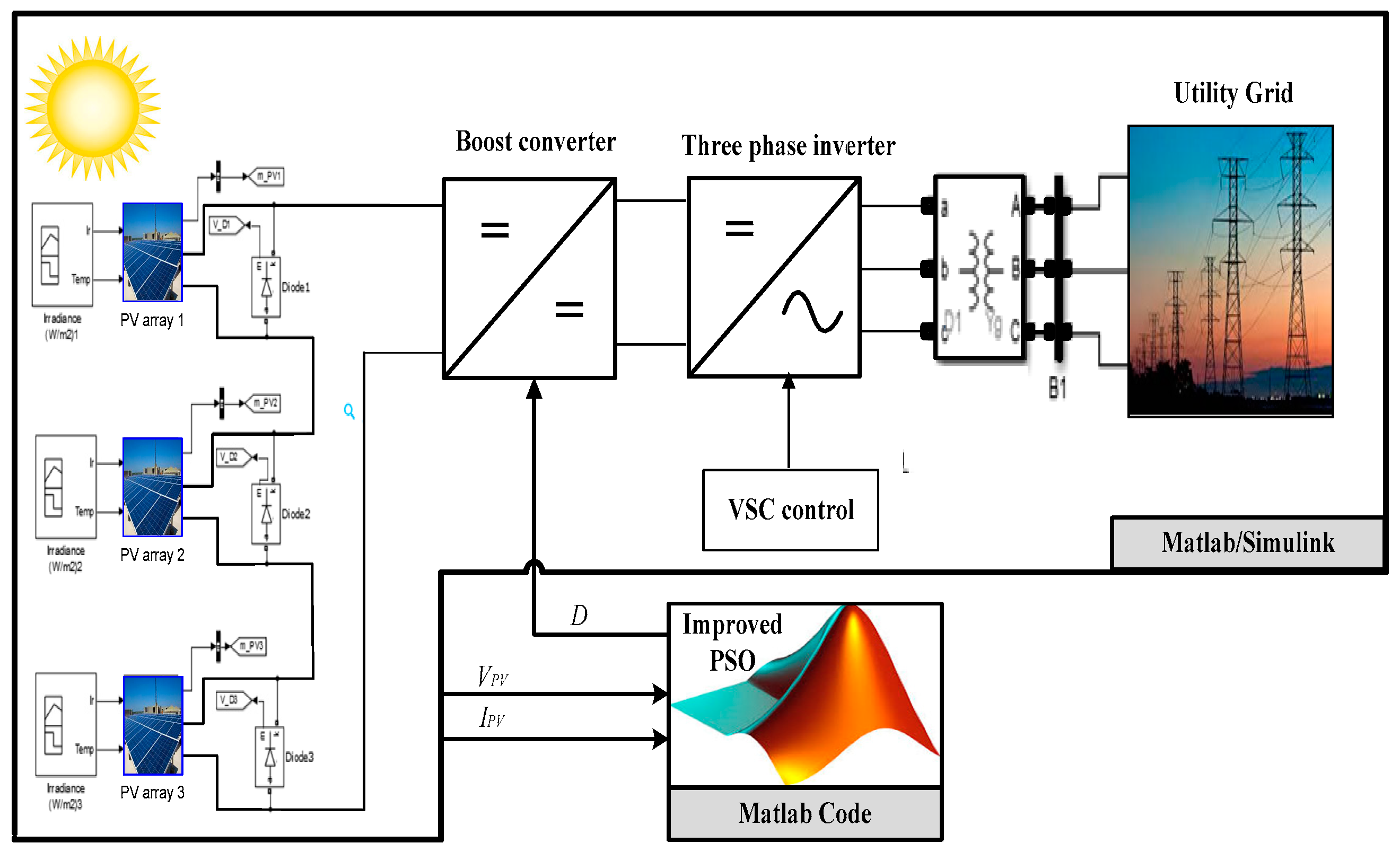
Figure 1. Modelling of the photovoltaic (PV) grid-connected system under partial shading.
Sustainability 11 02091 g001
Figure 2. Three different global peak (GMP) cases applied sequentially in this study.
Sustainability 11 02091 g002
Figure 3. Improved Particle Swarm Optimization (PSO) reinitialization flowchart based on predefined time (PDT).
Sustainability 11 02091 g003
Figure 4. Improved PSO reinitialization flowchart based on partial shading pattern change.
Sustainability 11 02091 g004
Figure 5. The PV output response under variant partial shading pattern based on PSO without reinitialization.
Sustainability 11 02091 g005
Figure 6. The PV output response under variant partial shading patterns based on improved PSO reinitialization upon PDT.
Sustainability 11 02091 g006
Figure 7. The PV output response under variant partial shading pattern based on improved PSO reinitialization upon the radiation change.
Sustainability 11 02091 g007
Table 1. Comparisons of the improved PSO using the two proposed methodologies with the conventional PSO.
SP No. Cases SP#1SP#2SP#3
Irradiance (W/m2)(1000, 300, 200)(800, 400, 900)(1000,700, 900)
GMP value (kW)54.692.8128.8
GMP place1st2nd3rd
VPV at GMP (V)124257402
PSO without reinitializationPPV (kW)54.649.654.8
VPV (V)124124124
PSO Efficiency100%53%43%
Improved PSO reinitialization upon PDTPPV (kW)54.649.6–92.854.8–128.8
VPV (V)124124–257257–402
Improved PSO Efficiency100%53% → 100%43% → 100%
Improved PSO reinitialization upon SP changePPV (kW)54.692.8128.8
VPV (V)124257402
Improved PSO Efficiency100%100%100%