Article

Development of a Homogenous Cement Slurry Using Synthetic Modified Phyllosilicate while Cementing HPHT Wells

by
Salaheldin Elkatatny
Department of Petroleum Engineering, King Fahd University of Petroleum & Minerals, Dhahran 31261, Saudi Arabia
Sustainability 2019, 11(7), 1923; https://doi.org/10.3390/su11071923
Submission received: 10 March 2019 / Revised: 27 March 2019 / Accepted: 27 March 2019 / Published: 31 March 2019

Abstract

:
Cement slurry segregation has a detrimental impact on the cement matrix efficiency in term of zonal isolation. In this study, synthetic modified phyllosilicate (SMP) dispersant, which is known as laponite RD is suggested to reduce the slurry segregation and enhance the vertical homogeneity of the cement matrix in term of density distribution. Seven cement slurries were prepared with different SMP concentrations using molds with different dimensions based on the targeted test, then cured for 24 h at 140 °C and 3000 psi using a high-pressure and high-temperature curing chamber. After that, the samples’ density distribution was evaluated using a direct density measurement and computer tomography (CT) scan imaging technique, and the effect of SMP on the cement rheological parameters, permeability, and compressive strength and were also evaluated. The performance of SMP was then compared with a commercial dispersant. As a result, 0.3% by weight of cement (BWOC) of SMP is found to considerably reduce the vertical density variation along the cement column to 0.46% compared with a density variation of 4.78% for the slurry with the commercial dispersant. The CT scan images confirmed the vertical homogeneity of the slurry with 0.3% BWOC of SMP. Addition of 0.3% BWOC of SMP increased the yield point of the cement slurry to 60.6 MPa compared with 20.5 MPa for the slurry with 0.25% of the commercial dispersant. Adding 0.3% BWOC of SMP into the cement formulation decreased the permeability by 37.1% compared with the commercial dispersant. The sample with 0.3% BWOC of SMP has a compressive strength of 43.9 MPa.

1. Introduction

Oil well cement (OWC) slurry, which contains different additives such as retarder, fluid loss agent, dispersant and heavy weight material, is pumped into oil wells to fill up the gap space between the casing and the drilled formations [1,2,3]. OWC is injected to achieve different objectives such as supporting the drilled weak formations and casings, preventing cross flow between the formations and wellbore and between the different layers, especially the flow from high-pressure zones to low pressure zones, and to isolate the oil-bearing zones from water-bearing layers [4,5,6,7,8].
While pumping the cement slurry inside the oil well down through the casing and up through the annulus between the casing and formations cement slurry have non-Newtonian yield-stress rheology and is characterized by different properties like the plastic viscosity and yield point, optimizing these properties is very important to ensure efficient displacement of the other fluids such as the drilling mud from the casing/formations annulus to achieve efficient zonal isolation [9]. Other properties such as cement static stability, strength build up rate, and its volumetric change characterize the cement transformation from slurry to solid state. After solidification, cement is characterized mainly by it is ability to withstand fracturing. Optimization of all these properties is essential for a robust and low permeability cement matrix [10].
Xu et al. [11] introduced a novel a cement sheath mechanical model for fracture wellbores, thermal loads and coupling pressure, that reflect the failure modes of de-bonding, shear failure, disking, and radial cracking. They concluded that the drops in the temperature of the well would lead to a major tri-axial tensile stress encourage the failure of the cement in the disking, de-bonding and radial cracking. The increase of the casing pressure will reduce the de-bonding hazard significantly but it will also make the shear failure and radial cracking worse and more serious. To make the cement sheath safety in the fractures wellbores, a high fluid temperature should be injected, and the circulation pump pressure should increase. Won et al. [12] concluded that low thermal conductivity of G-class cement may be reasonable for geothermal wells to avert heat loss in the production well.
Xi et al. [13] studied the effects of the mechanical parameters of the cement sheath on the decrease of the internal diameter of the casing. They concluded that as the cement sheath elasticity modulus increases, the decrease of the internal diameter of the casing will reduce. Also, they stated that, the reduction of cement sheath Poisson ratio decreases the reduction of casing’s diameter which mean that the low Poisson ratio is a benefit to save the casing’s integrity by reducing the decrease of internal diameter of the casing.
Tan et al. [14] examined the impacts of three types of starches on the cement properties in the alkali-activated type. The three types were corn starch (CS), carboxymethyl starch (CMS) and hydroxypropyl starch (HPS). They concluded that the three starches types have the ability to reduce the fluid loss, extend the setting time, and increase the apparent viscosity. Adding more starch under a temperature of 200 °C will increase the pores number, encouraged the filtering procedure which improve the self-degradation. By comparing the three types of starches, CMS is the most potential as a self-degradable added substance.
During cement placement, the slurry may lose its homogeneity because of solid segregation which considerably affect the flowability of cement [15] and in some cases make the cement unusable [16,17]. The static stability of the cement is one of the most important parameters to ensure vertical homogeneity in term of density variation between the top and bottom of the cement matrix in the casing/formations annulus. The static stability describes the ability of the cement slurry to maintain homogeneous density while at rest. When cement slurry reached the required height in the annulus, pumping will be stopped, then the solid particles of the cement will tend to settle down, and this will cause heterogeneous pressure gradient in the annulus whereby at the top of the cement formation the density and pressure gradient are lowest which may cause fluid flow from formation into the wellbore and if the formation fluid is gas, gas channeling through the unsolidified cement is expected which will persist after cement solidification. The density and pressure gradient at the bottom are highest, and hence, this may lead to formation fracturing especially in the weak zones [10]. Free water accumulation at the top of the cement column caused by slurry segregation is also expected [18], this means less of a cement column higher than the designed one. In the horizontal well, cement’s solids segregation leads to bad cement job in the upper part of the cemented annulus [19].
Laponite is layered silicate additive manufactured from natural inorganic sources which has been used for long time as a rheology modifier to improve the rheological characteristics of a wide range of waterborne products [20,21,22]. When laponite is added to a solution it reacts with the soluble components in the formulation to develop its viscosity [23]. Laponite products are able to disperse in water [24,25], beside addition of laponite into aqueous solutions considerably prevents aggregation of solid particles and enhances their dispersibility into the solution [26,27,28,29,30].
It is clear from the literature that cement homogeneity is a critical issue especially while cementing HPHT wells. The existing dispersion additives are not sufficient to solve the cement segregation. The main goal of this paper is to develop a new cement slurry based on synthetic modified phyllosilicate (SMP) to overcome the segregation issue.
In this study, the effect of SMP on class G oil well cement static stability is studied through different techniques and compared with the static stability of base cement (without any dispersant) and cement slurry incorporating a commercially available dispersant.

2. Methods and Materials

2.1. Materials

Seven cement slurries considered in this work were prepared using class G oil well cement, deionized water, dispersion agent, silica flour, defoamer, and fluid loss controller. The only difference between the seven cement formulations is the type and concentration of the dispersion agent while all other additives have same composition and concentration in all the seven slurries. Two dispersion agents were considered in this work, a commercial dispersant provided by a service company and an SMP, which is laponite RD with a specific gravity of 1.
As shown in Table 1 the first formulation considered in this study is the base slurry (i.e sample Base) which has no dispersion agent, the second formulation contains 0.25% by weight of cement (BWOC) of a commercially available dispersion agent which is provided by a service company. The cement formulation with the commercial dispersion was used to cement a deep well at a depth greater than 13000 ft where the circulating bottom hole temperature was about 230 °F, the static bottom hole temperature was about 290 °F, and the bottom hole pressure was 8500 psi. The slurries SMP1, SMP2, SMP3, SMP4, and SMP5 contain 0.1, 0.2, 0.3, 0.4, and 0.5% BWOC of SMP which is used as a dispersion agent to prevent the solids segregation for the cement slurry. Table 1 summarizes the composition of the seven cement slurries considered in this study.

2.2. Methods

Cement slurries with the compositions shown in Table 1 were prepared according to the American Petroleum institute (API) procedure [31]. After preparation, the slurries were poured into different molds depending the targeted test, and then cured at 140 °C and 3000 psi for 24 h using a high-pressure high-temperature (HPHT) curing chamber, after that the samples were tested for the effect of the dispersion agent in the density variation along the samples length in vertical direction, the cement slurry rheology, the unconfined compressive strength, and the permeability. The procedures followed in every test are summarized in the following sections.

2.3. Density Variation

Different techniques were considered is this study to evaluate the density variation. The samples used for this purpose are prepared using molds of 1.5 inch in diameter and 4 inches in length, while curing all molds are kept in vertically to be able to compare the change in the density from top to bottom of the samples. The vertical density variation along the length of these cylindrical samples was evaluated through two different techniques of computer tomography (CT) scan and direct density measurement. The direct density measurements were conducted in three different positions of the cylindrical samples (bottom, middle, and top), three small cement cylinders of 1.5 inch in diameter and 0.5 inch in length were cut out at the bottom, middle, and top of the cured cylinders.

2.4. Rheology

The effect of the SMP and the commercial dispersant (ComD) on the cement rheological parameter were evaluated. The gel strength (GS), yield point (YP), and plastic viscosity (PV) were evaluated for all the cement slurries under study.
The plastic viscosity and yield point are measured using the Fan 35 rheometer reading at 300 rpm and 600 rpm using Equations (1) and (2). During the rheological experiment, the shear stress values are recorded at different shear rates starting from 3 to 300 rpm, i.e., (3, 6, 100, 200, 300 rpm). The reading at 600 rpm was obtained by extrapolate the consistency curve which becomes as a straight line at higher shear rate. The reading was taken in ascending order and then descending order and the average between them was taken to calculate the shear stress values at two shear rates (300 and 600 rpm).
P V = R 600 R 300
Y P = R 300 P V
where PV is the plastic viscosity (cP), YP is the yield point (lb/100 ft2), R600 is the viscometer reading at 600 rpm, and R300 is the viscometer reading at 300 rpm.

2.5. Compressive Strength Test

Cubical molds of 2 × 2 × 2 inches3 were used for the purpose of compressive strength testing. The compressive strength of every cement slurry is calculated as the average unconfined compressive strength of three cement cubes of that slurry which are tested using the crushing machine.

2.6. Permeability

The cement samples permeability was measured on the cylindrical samples of 1.5 inches in diameter and 0.5 inches in length. The permeability was measured using nitrogen as the measuring fluid using a gas permeameter.

3. Results and Discussion

In the first parts of this section the effect of the SMP on the density variation, rheology, and permeability of the cement samples will be studied and compared with the base cement slurry formulation to select the optimum SMP concentration. In the final section, the performance of the cement slurry prepared with the optimum SMP concentration will be compared with the cement slurry prepared using a commercial dispersant currently in use in oil industry. A discussion of the expected additional cost to prepare one barrel of cement using the SMP will be presented.

3.1. Density Variation

The density variation vertically along the length of the cement samples was examined using the direct density measurement and CT scan technique. Figure 1 compares the density variation between the top, middle, and bottom of the different cement samples under study determined using direct density measurement, this figure also compares the density variation percentage (DV%) between top and bottom of all samples calculated using Equation (1).
D V % = ( D e n s i t y   a t   t o p D e n s i t y   a t   b o t t o m ) D e n s i t y   a t   b o t t o m × 100
As indicated in Figure 1 sample Base has a considerable density variation vertically along its length with the density at bottom of 2.31 g/cm3, at middle is 2.27 g/cm3, and at top is 2.13 g/cm3. The density at the top of the sample Base is 7.79% less than the density at the bottom. Sample SMP1 with 0.1% BWOC of the SMP has a density variation of 8.47% between the top and bottom. Incorporating ≥0.2% BWOC of SMP with into the cement formulation reduced the vertical density variation of the solidified cement matrix, sample SMP2 has density variation of 3.57% along its length from top to bottom. The density variation between top and bottom of sample SMP3 is only 0.46% which is the lowest among all other samples with the densities of 2.16, 2.16, and 2.15 g/cm3 at bottom, middle, and top of sample SMP3. Samples SMP4 and SMP5 have density variations of 5.70% and 2.22%, respectively.
The CT scanning technique was also used to compare the change in the density of the all samples under study. The CT scan images recorded at different positions through the cylindrical samples from the top to the bottom of the samples are shown in Figure 2, which shows that the density variation at different sections vertically along the length of the cement samples as indicated by different colors. The yellow color denotes the regions with the highest density, then the green color regions have lower density, followed by the orange and red colored regions, and the blue color represents the regions with the lowest density. The samples where the CT images at different position in the sample contain most of these colors indicating large density variations, while the samples with less color variation indicate less density difference at different positions in the sample.
For the sample Base, the slices at top are almost blue indicating very low density, which changes to almost red for the slices at middle and to orange and yellow mixture at bottom as shown in Figure 2a, for this sample (Base) the CT image have a wide range of colors confirming the huge difference in the density along the vertical length of the samples. The same variation in the slices colors is noticed for samples SMP1 and SMP2 which have 0.1% and 0.2% BWOC of SMP as shown in Figure 2b,c, respectively. Sample SMP3 has the lowest colors variation for the different slices as indicated in Figure 2d, where all slices along the sample have almost sample color confirming that for this sample there is no vertical density variation along the sample length. The density variation in samples SMP4 and SMP5 is also high as confirmed by the wide ranges of different colors in different slices of these samples where the slices colors are changing from blue at the top to red in the middle and yellow at the bottom as shown in Figure 2e,f, respectively.
The previous results confirmed that 0.3% BWOC of SMP is the optimum concentration to prevent the solids segregation. So, in the next sections the effect of using 0.3% BWOC of SMP on the rheological parameters, compressive strength, and permeability of the cement will be studied.

3.2. Effect on Rheological Parameters

The effect of the SMP on the rheological characteristics of cement slurry was evaluated. As shown in Figure 3, the base cement has PV and YP of 381 cP and 44.6 lbf/100 ft2, respectively. Incorporating 0.3% BWOC of SMP into sample SMP3 did not affect the PV compared with the base slurry while it considerably increased the YP to reach 60.644 lbf/100 ft2 with an increase of 26.4% compared with the base slurry. This increase in the YP of the slurry is important to improve the carrying capacity of the cement slurry and, in this case, it confirms the ability of the SMP3 slurry to prevent solids segregation as compared with the base sample addressed in the previous sections.
Figure 4 compares the 10-sec and 10-min gel strength of samples Base and SMP3. The 10-sec and 10-min gel strengths of the base slurry (Base) are 9.59 and 24.1 lbf/100 ft2, respectively. Addition of 0.3% BWOC of SMP into the cement slurry increased slightly both 10-sec and 10-min gel strengths, the 10-sec and 10-min gel strengths of sample SMP3 are 10.57 and 28.38 lbf/100 ft2, respectively.

3.3. Effect on the Permeability

Figure 5 compares the permeability of cement samples Base and SMP3. The permeability of sample Base which has no SMP is 0.053 mD. Sample SMP3 has a permeability of 0.039 mD which is 26.4% less than the permeability of the base cement by 40%.

3.4. Comparison of the Synthetic Modified Phyllosilicate (SMP) with a Commercial Dispersant

In this part of the study, the effect of adding 0.3% BWOC of SMP to class G cement slurry on the slurry properties will be compared to a commercially available dispersant. Figure 6 compares the density variation between the top, middle, and bottom of the samples ComD and SMP3 determined using direct density measurement, this figure also compares the density variation percentage (DV%) between top and bottom of all samples calculated using Equation (1). As indicated in Figure 6 the densities at bottom and top of sample ComD are 2.30 and 2.19 g/cm3, with 4.78% density variation between the top and bottom. The densities bottom, middle, and top of sample SMP3 are 2.16, 2.16, and 2.15 g/cm3, respectively, with variation along the sample length of only 0.46% which is 90.4% less that the density variation along sample ComD.
Figure 7 compares the CT scan images for sample ComD which contains 0.25% BWOC of commercially available dispersant and sample SMP3 that contains 0.3% of SMP which as confirmed by the previous discussion is found to be the optimal SMP concentration to improve the cement homogeneity, Figure 7b confirms that sample SMP3 is more homogeneous in term of density distribution along the sample as confirmed by the presence of the same color in all the CT images (red) along the sample compared with sample ComD Figure 7a.
Figure 8 compares the plastic viscosity and yield point of samples ComD and SMP3. The plastic viscosities of samples ComD and SMP3 are 400 and 367 cp, respectively, which indicates that the plastic viscosity of sample SMP3 is 8.25% less than that of sample ComD. Although the decrease in the plastic viscosity is small, it is important to ensure the improvement of the injectability of the slurry. The yield point of sample SMP3 is 60.6 lbf/100 ft2 which is 196% greater than the yield point of sample ComD of 20.5 lbf/100 ft2 as indicated in Figure 8. The increase in the slurry yield point of sample SMP3 is the essential property that improved its ability to prevent solids settling.
The 10-sec and 10-min gel strengths of samples ComD and SMP3 are summarized in Figure 9. Addition of 0.3% of SMP increased the 10-sec and 10-min gel strengths by 0.98 and 2.4 lbf/100 ft2 compared to sample ComD.
Figure 10 compares the permeability of samples ComD and SMP3. This figure indicates that the permeability of the cement sample prepared with 0.3% of SMP has a permeability of 0.039 mD which is 37.1% less than the permeability of 0.062 mD for the sample prepared with the commercial dispersant.
Figure 11 compares the compressive strengths of samples Base, ComD, and SMP3. This figure indicates that the compressive strength of the base sample (i.e., sample Base) is 67.3 MPa. Addition of both dispersants reduced the cement compressive strength, the compressive strength for the sample with 0.25% of the commercial dispersant (i.e., sample ComD) is 51.2 MPa compared to strength of 43.9 MPa for sample SMP3, but still these strengths are high enough to ensure good zonal isolation and wellbore stability.

4. Additional Cost to Prepare One Barrel of the New Cement

In this section, the additional cost to prepare one barrel of the new cement with a slurry density of 16 pound per gallon (ppg) will be discussed. The cost of the SMP is $16.8/kg, and to prepare one barrel of the slurry with a density of 16 ppg and SMP concentration of 0.3% BWOC, 0.896 kg of the SMP is needed. So, the additional cost of the new cement is $15/barrel of slurry. Note in this case, the cost of the commercial dispersant used before to prepare the slurry must be subtracted from the total cost.

5. Conclusions

In this study, the effect of SMP dispersant on improving class G oil well cement static stability is evaluated and compared with the performance of commercially available dispersant. The effect of different concentrations of SMP on the cement density distribution vertically along the cement column, the rheological characteristics, permeability, and compressive strength of cement were evaluated. Based on the results obtained, the following conclusions can be drawn:
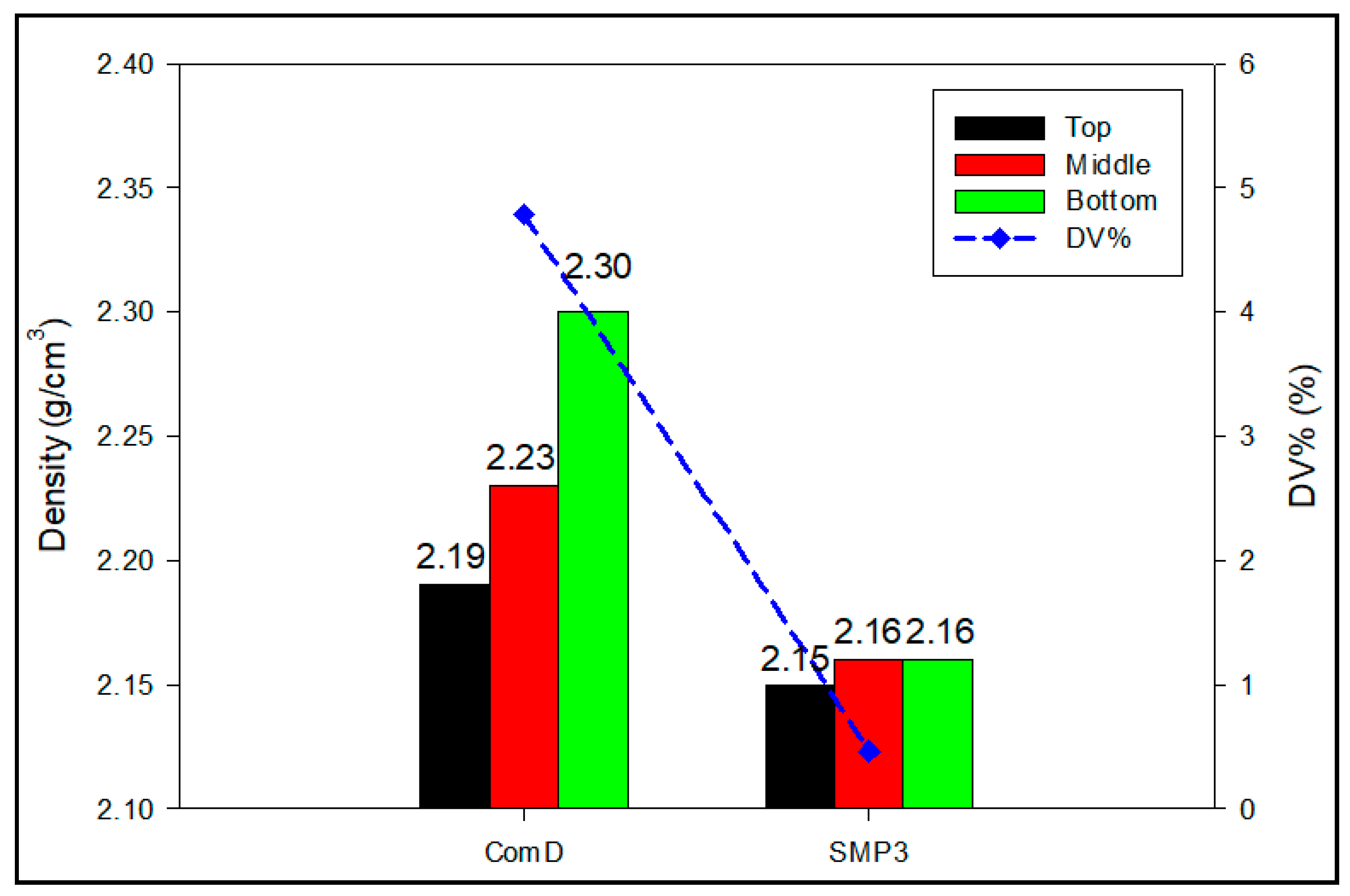
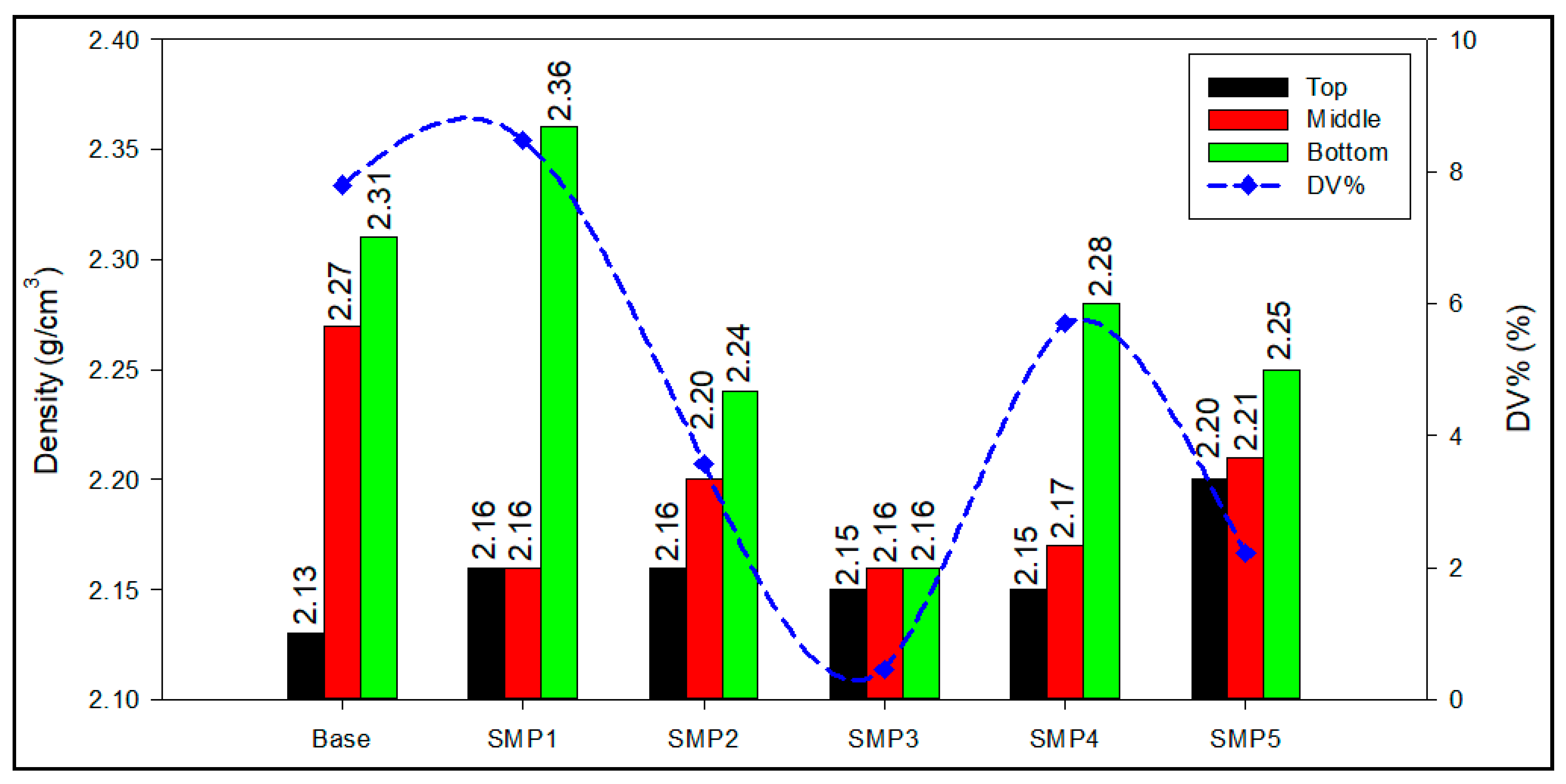
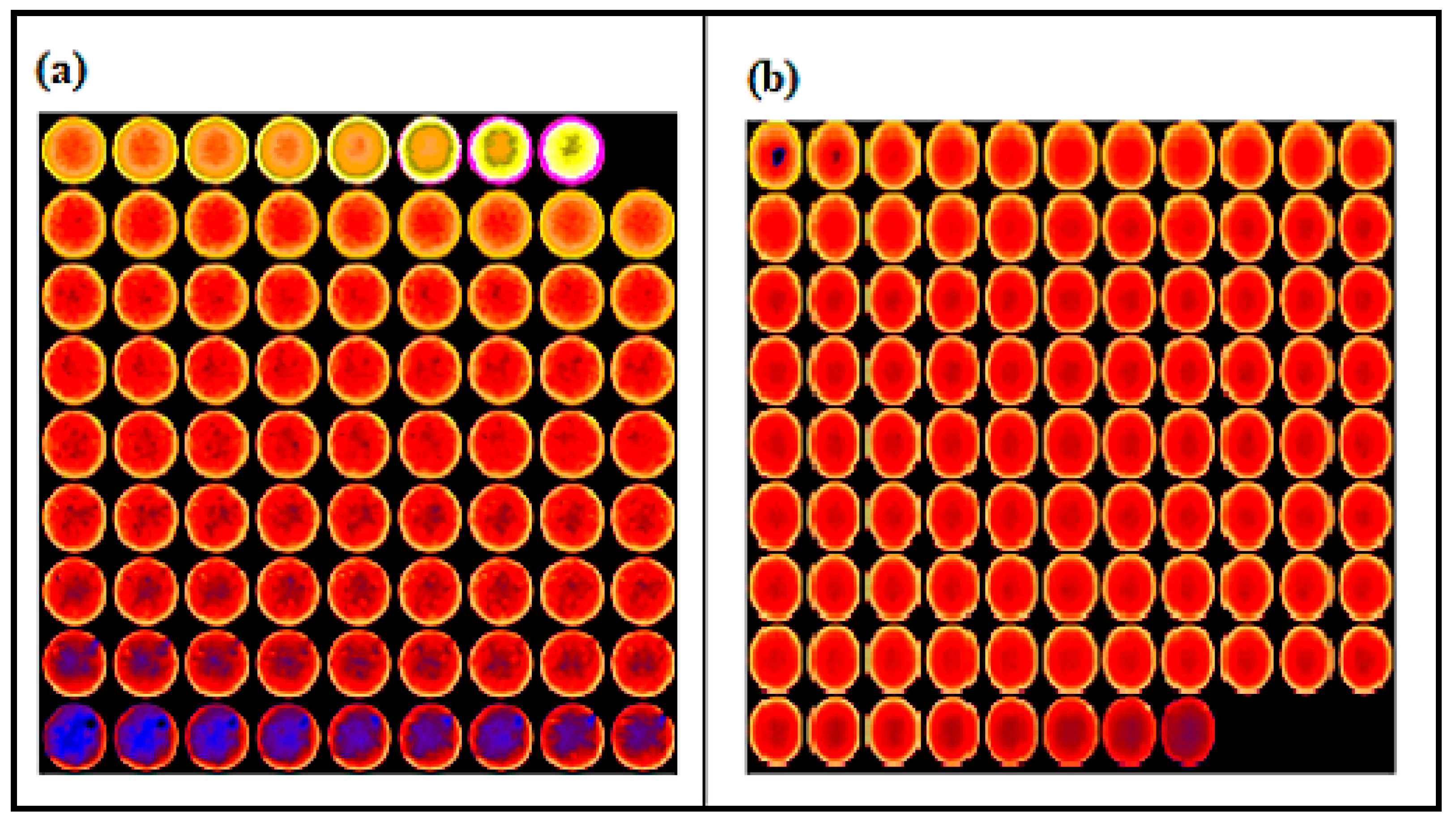
  • 0.3% BWOC of SMP was found to prevent slurry segregation with density variation at the top and bottom of the cement column of 0.46% compared with a density variation of 4.78% for the cement incorporating the commercial dispersant.
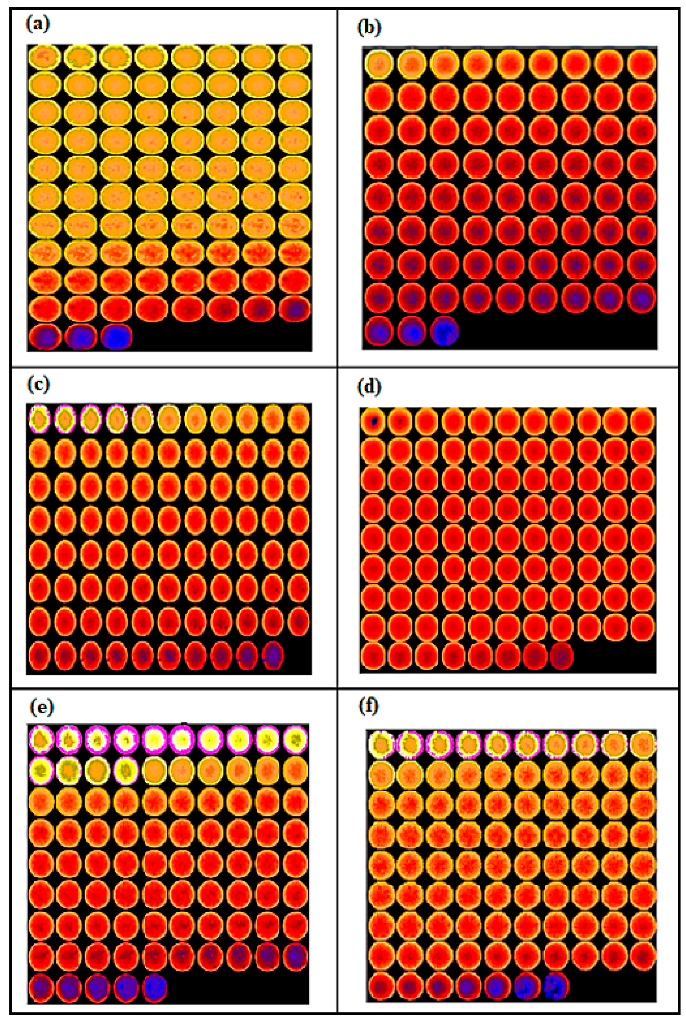
  • The CT scan imaging confirmed the homogeneous density distribution along the cement column for the samples incorporating 0.3% BWOC of SMP.
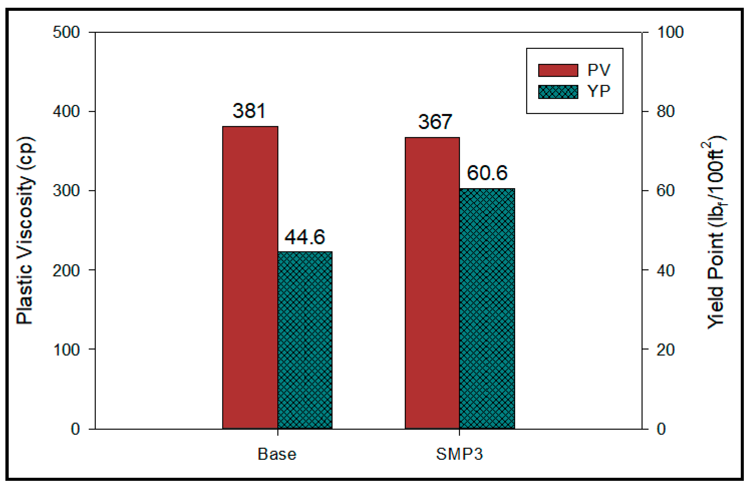
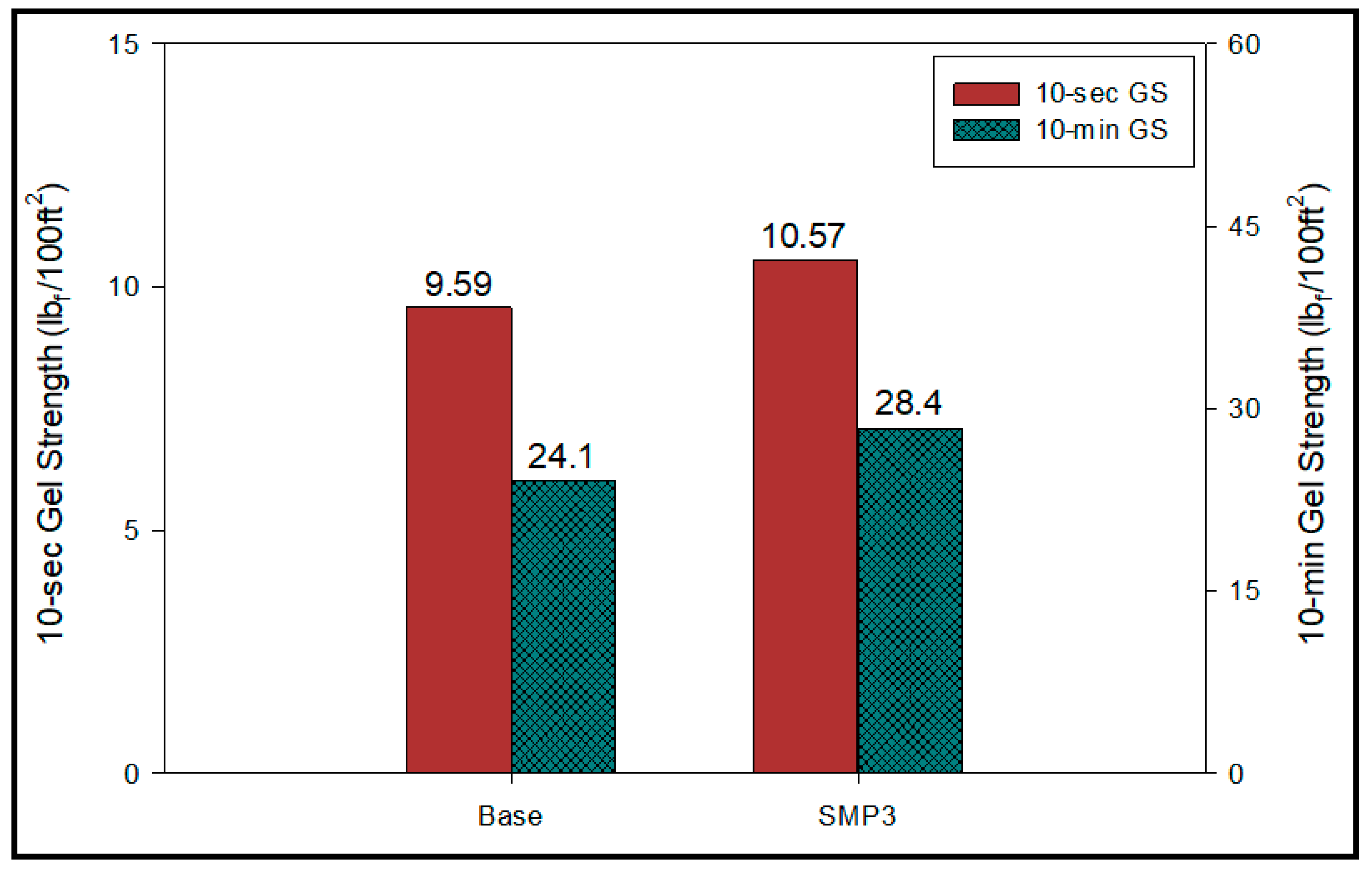
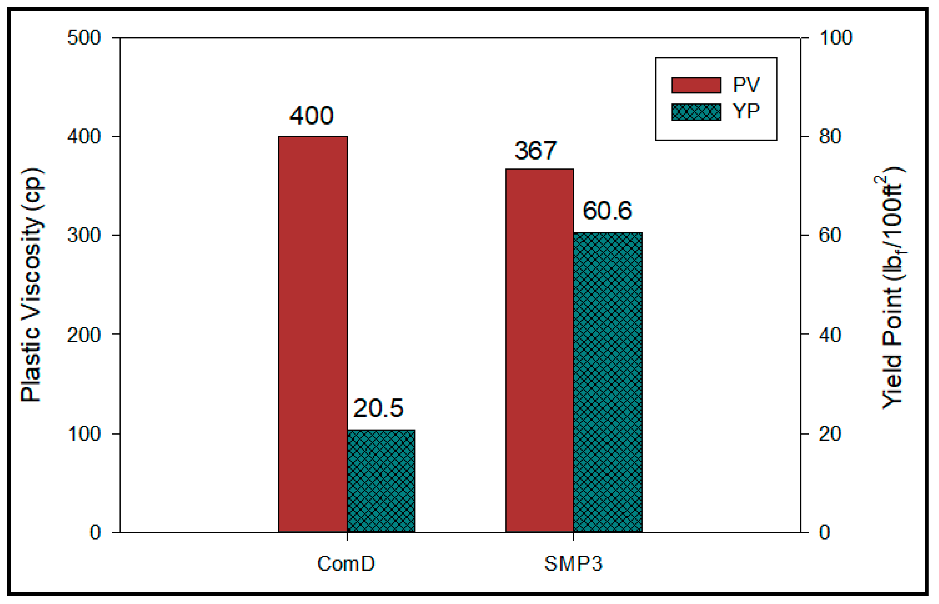
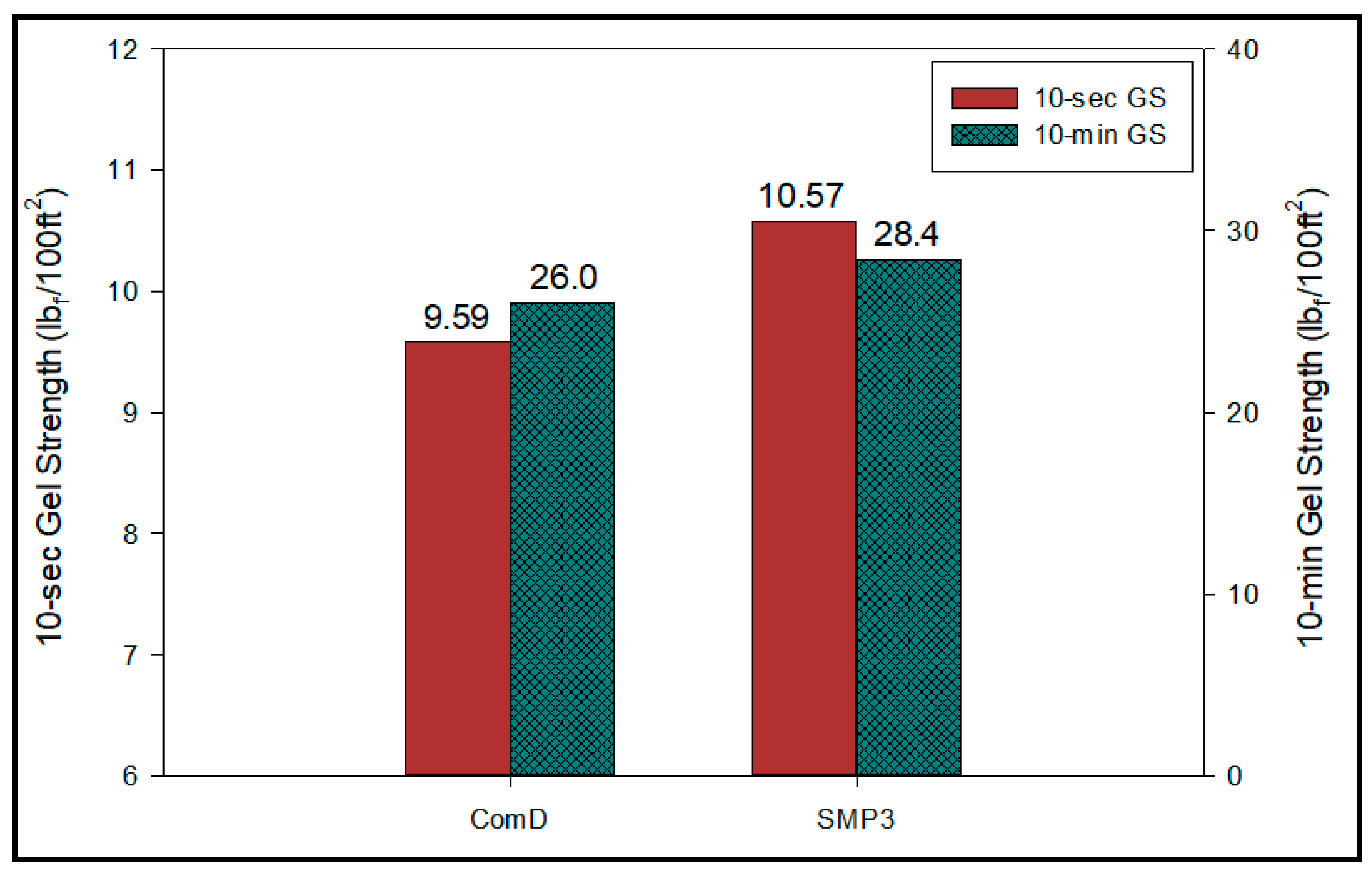
  • The plastic viscosity, 10-sec, and 10-min gel strengths of the sample with the commercial dispersant and the sample with 0.3% BWOC of SMP are almost same.
  • Addition of 0.3% BWOC of SMP increased the yield point of the cement slurry to 60.6 lbf/100 ft2 compared with 20.5 lbf/100 ft2 for the slurry with 0.25% BWOC of the commercial dispersant.
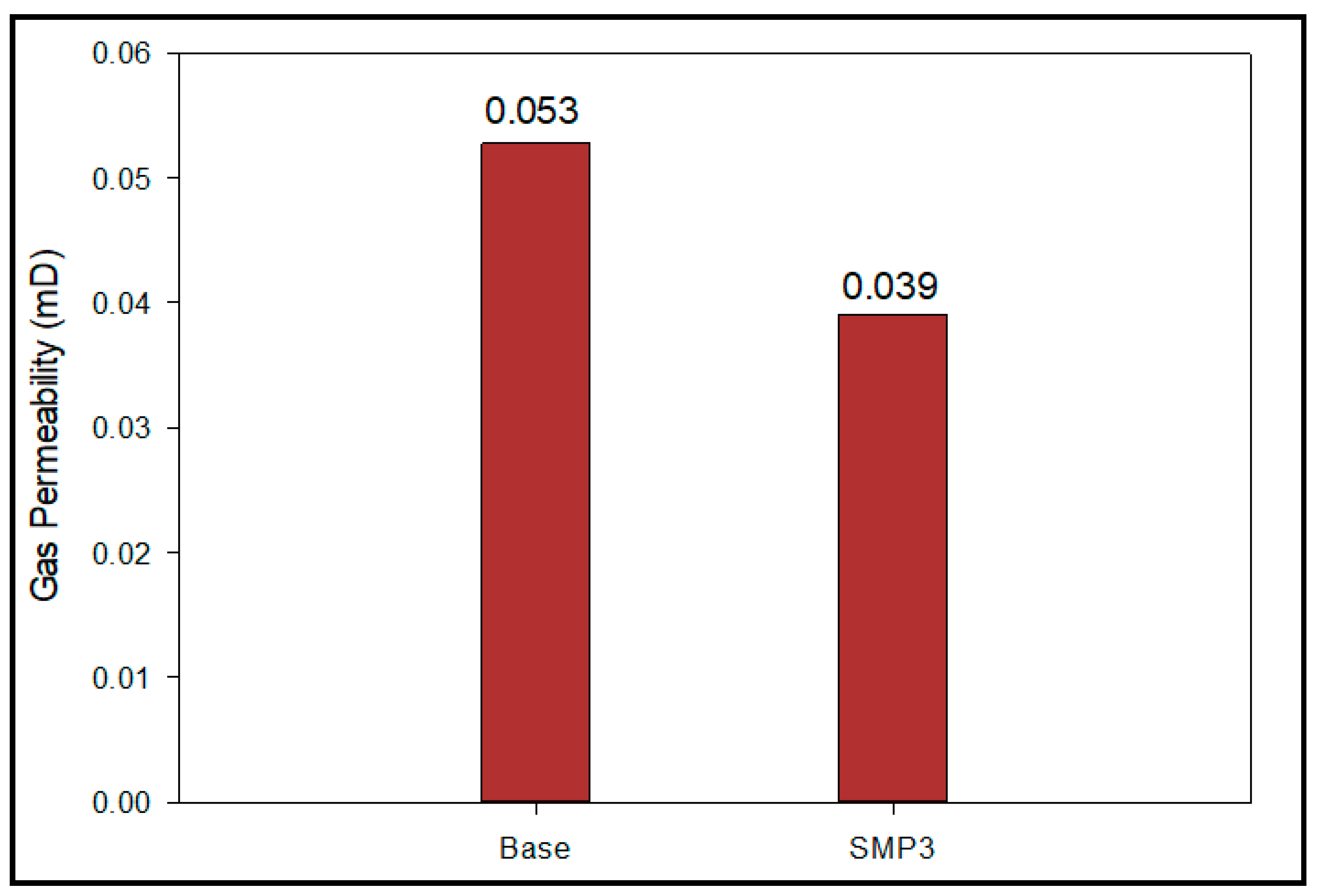
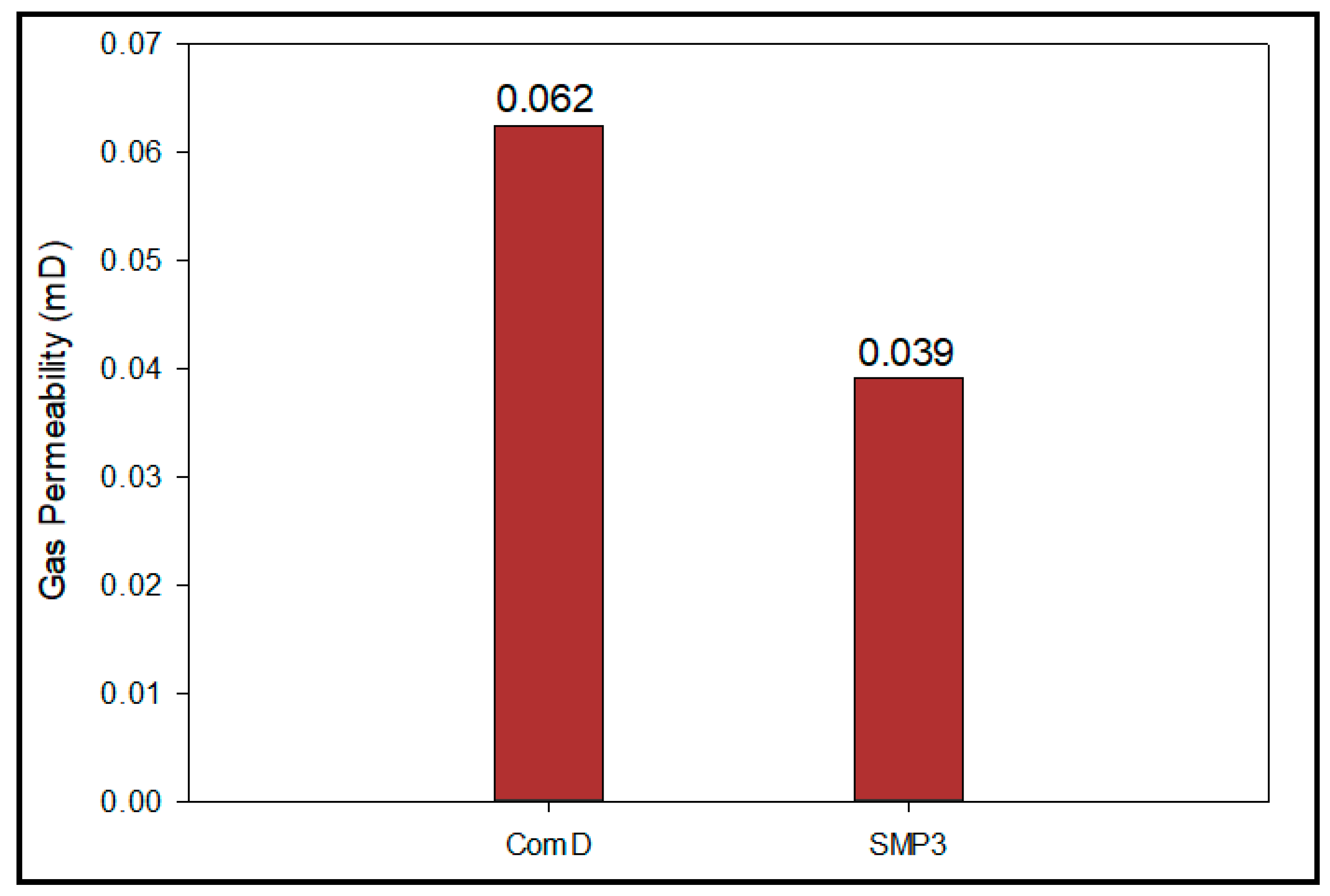
  • Incorporating 0.3% BWOC of SMP decreased the permeability by 37.1% compared with the sample containing the commercial dispersant.
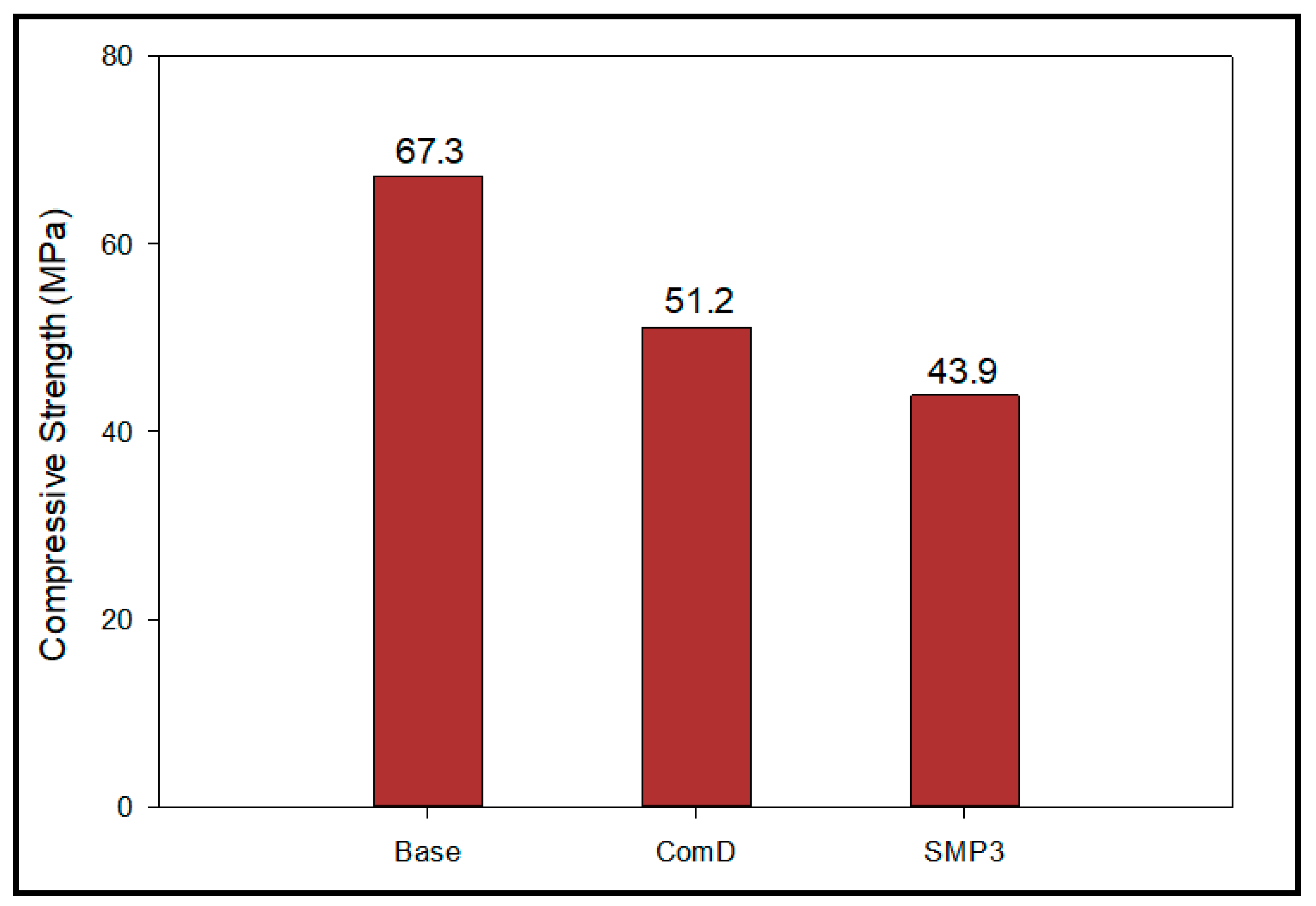
  • Addition of both SMP and commercial dispersant decreased the cement compressive strength compared with the cement without dispersant. The sample with 0.3% BWOC of SMP has compressive strength of 43.9 MPa, which is still greater than the minimum acceptable compressive strength for an oil well cement matrix.

Funding

This research received no external funding.

Conflicts of Interest

The author declares no conflict of interest.

Abbreviations

HPHTHigh-pressure high-temperature
SMPSynthetic modified phyllosilicate
BWOCBy weight of cement
CTComputer tomography
OWCOil well cement
CSCorn starch
CMSCarboxymethyl starch
HPSHydroxypropyl starch
APIAmerican petroleum institute
ComDCommercial dispersant
DVDensity variation, %
PVPlastic viscosity, cP
YPYield point, lb/ 100 ft2
GSGell strength, lb/ 100 ft2
ppgpound per gallon

References

  1. Pace, R.S.; McElfresh, P.M.; Cobb, J.A.; Smith, C.L.; Olsberg, M.A. Improved Bulk Blending Techniques for Accurate and Uniform Cement Blends. In Proceedings of the Paper SPE-13041-MS Presented at the SPE Annual Technical Conference and Exhibition, Houston, TX, USA, 16–19 September 1984. [Google Scholar]
  2. Cobb, J.A.; Pace, R.S. Elements Affecting Thickening Time of a Cement Blend. Paper SPE-14195-MS Presented at the SPE Annual Technical Conference and Exhibition, Las Vegas, NV, USA, 22–26 September 1985. [Google Scholar] [CrossRef]
  3. Gerk, R.R.; Simon, J.M.; Logan, J.L.; Sabins, F.L. A-Study of Bulk Cement Handling and Testing Procedures. Soc. Pet. Eng. 1990. [Google Scholar] [CrossRef]
  4. Adams, N. Drilling Engineering: A Complete well Planning Approach; PennWell Publishing Company: Tulsa, OK, USA, 1985. [Google Scholar]
  5. Bourgoyne, A.T., Jr.; Chenevert, M.E.; Millheim Keith, K.; Young, F.S., Jr. Applied Drilling Engineering; Society of Petroleum Engineers, Inc.: Houston, Texas, USA, 1986. [Google Scholar]
  6. Rabia, H. Well Engineering and Construction; Entrac Consulting. Entrac Petroleum: London, UK, 2001. [Google Scholar]
  7. Minaev, K.; Gorbenko, V.; Ulyanova, O. Lightweight Cement Slurries based on vermiculite. In Proceedings of the IOP Conference Series: Earth and Environmental Science, Tomsk, Russia, 7–11 April 2014; Volume 21. [Google Scholar]
  8. Hossain, M.; Al-Majed, A.A. Fundamentals of Sustainable Drilling Engineering; John Wiley & Sons: Hoboken, NJ, USA, 2015. [Google Scholar]
  9. Bourlon, A.J.G.; Roy-Delage, S.L.; Taoutaou, S. An Innovative Methodology to Assess Cement Blend Flowability and Proneness to Segregation—A Step Forward to Higher Quality. Soc. Pet. Eng. 2017. [Google Scholar] [CrossRef]
  10. Lavrov, A.; Torsæter, M. Physics and Mechanics of Primary Well Cementing, Chapter two. In Petroleum Geoscience & Engineering; SpringerBriefs: Berlin, Germany, 2016. [Google Scholar]
  11. Xu, H.; Ma, T.; Peng, N.; Yang, B. Influences of Fracturing Fluid Injection on Mechanical Integrity of Cement Sheath under Four Failure Modes. Energies 2018, 11, 3534. [Google Scholar] [CrossRef]
  12. Won, J.; Choi, H.; Lee, H.; Choi, H. Numerical Investigation on the Effect of Cementing Properties on the Thermal and Mechanical Stability of Geothermal Wells. Energies 2016, 9, 1016. [Google Scholar] [CrossRef]
  13. Xi, Y.; Li, J.; Liu, G.; Li, J.; Jiang, J. Mechanisms and Influence of Casing Shear Deformation near the Casing Shoe, Based on MFC Surveys during Multistage Fracturing in Shale Gas Wells in Canada. Energies 2019, 12, 372. [Google Scholar] [CrossRef]
  14. Tan, H.; Zheng, X.; Ma, L.; Huang, H.; Xia, B. A Study on the Effects of Starches on the Properties of Alkali-Activated Cement and the Potential of Starch as a Self-Degradable Additive. Energies 2017, 10, 1048. [Google Scholar] [CrossRef]
  15. Bourlon, A.J.G.; Roy-Delage, S.L.; Taoutaou, S. A Step Forward to Assess Cement Blend Flowability and Proneness to Segregation: Cases Histories. Soc. Pet. Eng. 2017. [Google Scholar] [CrossRef]
  16. Williams, J.C. Mixing and Segregation in Powders. In Principles of Powder Technology; Rhodes, M.J., Ed.; Wiley: Hoboken, NJ, USA, 1990; pp. 71–90. [Google Scholar]
  17. Williams, J.C. The Storage and Flow of Powders. In Principles of Powder Technology; Rhodes, M.J., Ed.; Wiley: Hoboken, NJ, USA, 1990; pp. 91–118. [Google Scholar]
  18. Nelson, E.B.; Guillot, D. Well Cementing; Schlumberger: Houston, TX, USA, 2006. [Google Scholar]
  19. Bassett, J.; Watters, J.; Combs, N.K.; Nikolaou, M. Lowering Drilling Cost, Improving Operational Safety, and Reducing Environmental Impact through Zonal Isolation Improvements for Horizontal Wells Drilled in the Marcellus Shale. Paper URTEC-1582346-MS Presented at the SPE/AAPG/SEG Unconventional Resources Technology Conference, Denver, CO, USA, 12–14 August 2013. [Google Scholar] [CrossRef]
  20. Negrete, H.N.; Letoffe, J.-M.; Putaux, J.-L.; David, L.; Bourgeat-Lami, E. Aqueous dispersions of silane-functionalized Laponite clay platelets. A first step toward the elaboration of water-based polymer/clay nanocomposites. Langmuir 2004, 20, 1564–1571. [Google Scholar] [CrossRef]
  21. Sun, K.; Kumar, R.; Falvey, D.E.; Raghavan, S.R. Photogelling colloidal dispersions based on light-activated assembly of nanoparticles. J. Am. Chem. Soc. 2009, 131, 7135–7141. [Google Scholar] [CrossRef] [PubMed]
  22. Ghadiri, M.; Hau, H.; Chrzanowski, W.; Agus, H.; Rohanizadeh, R. Laponite clay as a carrier for in situ delivery of tetracycline. RSC Adv. 2013, 3, 20193–20201. [Google Scholar] [CrossRef]
  23. Bienia, M.; Danglade, C.; Lecomte, A.; Brevier, J.; Pagnoux, C. Cylindrical Couette flow of Laponite dispersions. Appl. Clay Sci. 2018, 162, 83–89. [Google Scholar] [CrossRef]
  24. Thompson, D.W.; Butterworth, J.T. The nature of laponite and its aqueous dispersions. J. Colloid Interface Sci. 1990, 151, 236–243. [Google Scholar] [CrossRef]
  25. Mohanty, R.P.; Joshi, Y.M. Chemical stability phase diagram of aqueous Laponite dispersions. Appl. Clay Sci. 2016, 119, 243–248. [Google Scholar] [CrossRef]
  26. Loginov, M.; Lebovka, N.; Vorobiev, E. Laponite assisted dispersion of carbon nanotubes in water. J. Colloid Interface Sci. 2012, 365, 127–136. [Google Scholar] [CrossRef] [PubMed]
  27. Manilo, M.; Lebovka, N.; Barany, S. Characterization of the electric double layers of multi-walled carbon nanotubes, laponite and nanotube+laponite hybrids in aqueous suspensions. Colloids Surf. A Physicochem. Eng. Asp. 2014, 462, 211–216. [Google Scholar] [CrossRef]
  28. Manilo, M.V.; Lebovka, N.; Barany, S. Combined effect of cetyltrimethylammonium bromide and laponite platelets on colloidal stability of carbon nanotubes in aqueous suspensions. J. Mol. Liq. 2017, 235, 104–110. [Google Scholar] [CrossRef]
  29. Manilo, M.V.; Lebovka, N.I.; Barany, S. Stability of multi-walled carbon nanotube+laponite hybrid particles in aqueous suspensions. Colloids Surf. A Physicochem. Eng. Asp. 2015, 481, 199–206. [Google Scholar] [CrossRef]
  30. Silva, J.M.; Barud, H.S.; Meneguin, A.B.; Constantino, V.R.L.; Ribeiro, S.J.L. Inorganic-organic bio-nanocomposite films based on Laponite and Cellulose Nanofibers (CNF). Appl. Clay Sci. 2019, 168, 428–435. [Google Scholar] [CrossRef]
  31. American Petroleum Institute (API). Worldwide Cementing Practices; API: Dallas, TX, USA, 1991. [Google Scholar]
Figure 1. Density variation vertically along the length of the cement samples.
Sustainability 11 01923 g001
Figure 2. Density variation vertically along the length of the cement samples through computer tomography (CT) scan technique for samples (a) Base, (b) synthetic modified phyllosilicate 1 (SMP1), (c) SMP2, (d) SMP3, (e) SMP4, and (f) SMP5.
Sustainability 11 01923 g002
Figure 3. Comparison of the plastic viscosity and yield point for samples Base and SMP3.
Sustainability 11 01923 g003
Figure 4. Comparison of the 10-sec and 10-min gel strengths for samples Base and SMP3.
Sustainability 11 01923 g004
Figure 5. Permeability change for samples Base and SMP3.
Sustainability 11 01923 g005
Figure 6. Comparison of the density variation vertically along the length of the samples ComD and SMP3.
Sustainability 11 01923 g006
Figure 7. Comparison of the density variation vertically along the length of samples (a) ComD and (b) SMP3, through using the CT scan technique.
Sustainability 11 01923 g007
Figure 8. Comparison of the plastic viscosity and yield point for samples ComD and SMP3.
Sustainability 11 01923 g008
Figure 9. Comparison of the 10-sec and 10-min gel strengths for samples ComD and SMP3.
Sustainability 11 01923 g009
Figure 10. Comparison of the permeability of samples ComD and SMP3.
Sustainability 11 01923 g010
Figure 11. Comparison of the compressive strengths of samples Base, ComD, and SMP3.
Sustainability 11 01923 g011
Table 1. Cement slurries compositions.
SlurriesCementWaterDispersion AgentSilica FlourDefoamerExpandable AgentFluid Loss Controller
Base600440354.7E-0710.75
ComD600440.25 *354.7E-0710.75
SMP1600440.1354.7E-0710.75
SMP2600440.2354.7E-0710.75
SMP3600440.3354.7E-0710.75
SMP4600440.4354.7E-0710.75
SMP5600440.5354.7E-0710.75
Cement in grams and all other additives are in by weight of cement (BWOC). * The dispersion agent used to prepare sample ComD is different than the dispersion agent considered in the other samples, this dispersion agent is provided by a service company and is the currently available dispersant used in oil industry.

