Article

Numerical Study of a New Solar Vacuum Tube Integrating with Phase Change Material

1
Jiangsu Provincial Key Laboratory of Solar Energy Science and Technology, Southeast University, Nanjing 210096, China
2
Key Lab of Energy Thermal Conversion and Control of Ministry of Education, School of Energy and Environment, Southeast University, Nanjing 210096, China
*
Author to whom correspondence should be addressed.
Sustainability 2019, 11(24), 6960; https://doi.org/10.3390/su11246960
Submission received: 30 October 2019 / Revised: 25 November 2019 / Accepted: 3 December 2019 / Published: 6 December 2019
(This article belongs to the Special Issue Solar Thermal Power Systems)

Abstract

:
In this work, a new solar vacuum tube (SVT) integrating with phase change material is introduced and numerically investigated. The mathematical model and the numerical solution of phase change heat transfer is introduced. The heat transfer of the solar energy collection system during the energy storage process is simulated. Solid-liquid phase change characteristics of the SVT with paraffin inside is analyzed. Optimization analysis of fin structure parameters (fin thickness and fin spacing) in the vacuum tube is conducted. The results showed that the metal fin has a great effect on the phase change heat transfer of paraffin in SVTs. The closer the paraffin is to the fins, the more uniform the paraffin temperature is and the sooner the paraffin melts. As the fin thickness increases and the spacing between the fins decreases, the melting time of the paraffin decreases. Meanwhile, the effect of fin spacing on the overall heat transfer performance of the phase change energy storage tube is larger than the effect of the fin thickness. When the fin thickness is 2 mm, the melting time of paraffin with a fin spacing of 80 mm is 21,000 s, which is almost three times of that with a fin spacing of 10 mm (7400 s). Therefore, decreasing fin spacing is an effective way of enhancing phase change heat transfer. When the total fin volume is constant, a SVT with small fin space and small fin thickness performs better in heat transfer performance.

1. Introduction

The booming development of the renewable energy applications, such as solar energy, necessitates efficient energy storage methods to accommodate the intermittency caused by the uncontrollable weather variation [1]. Thermal energy storage (TES) can alleviate the temporary mismatch between supply and demand [2]. Phase change materials (PCMs) are widely used in TES due to their excellent energy storage capacity [3,4,5]. However, some PCMs, such as paraffin, have the shortcoming of low thermal conductivity. To strengthen the heat transfer performance of PCMs, TES using PCMs and fins has drawn increasing attention [6,7].
Due to many advantages of PCMs, plenty of research on the application of PCMs in TES has been investigated to improve the storage ability. Kabeel et al. [8] conducted an experiment to investigate the performance changes of the flat and v-corrugated plate solar air heaters after using paraffin wax as a PCM. It showed that the outlet temperature of the air was significantly improved, and the daily efficiency was 12% higher when the PCM was used. In another study [9], paraffin wax was also used as a PCM to analyze its performance. The results showed that paraffin wax enabled excess energy storage when there was energy supplied, and the temperature advantage of the PCM case reached 13–14 °C after the heater was switched off for 16 h, compared with the conventional heat storage case. For other kinds of PCMs, Canbazoğlu et al. [10] used a conventional open-loop passive solar water-heating system combined with different kinds of salt hydrate-PCMs to explore the system performance, and the results also showed similar enhancement effect. For the numerical simulation part, Belmonte et al. [11] carried out a study of a fluidized bed TES unit containing PCMs. The simulation results showed that its thermal energy charging/discharging was better due to the latent heat of PCMs. Furthermore, Veerappan et al. [12] investigated the phase change behavior of several PCMs by analytical models for solidification and melting. The results showed good agreement with the previous experimental studies.
Paraffin, as a kind of PCM, has many advantages, such as being less prone to chemical reactions, having no phase separation and corrosion, a low price, and so on. However, it has the shortcoming of low thermal conductivity. Therefore, fins are used to improve the thermal conductivity ability. In the study of Amina et al. [13], the solar absorber with inserted fins obtained a 1.3 to 1.8 times augmentation of the Nusselt number compared to the smooth tube model. Eslamnezhad et al. [14] studied the heat transfer for PCMs in a triplex tube heat exchanger with selected arrangements of fins. The results showed that all of them shortened the melting time effectively. Kumar et al. [15] presented a forced convection solar air heater to improve the performance of TES. The pin-fin was used in the absorber plate. Compared with the flat absorber plate, the solar air heater could have 2–5 °C higher outlet air temperature and better thermo-hydraulic efficiency.
With the rapid development of computational fluid dynamics, numerical simulation methods have been widely used in the studies of TES. Ismail et al. [16] developed a model to investigate the effect of different fin parameters on the thermal performance of TES. The results confirmed the importance of fins and showed that the fin parameters have a significant effect on the solidification time. In another study conducted by Sheikholeslami et al. [17], fins with an innovative structure are applied for performance enhancement, and the response surface method is used to find a better fin array. A pretty good enhancement is obtained during the discharging process of TES, especially with the optimized snowflake shaped fin. Lorenzini et al. [18] conducted a geometric optimization of the Y-shaped assembly of fins using constructal design. The minimized global thermal resistance is studied by the parametric study. Furthermore, there has been much research [19,20,21] conducted to investigate the effect of a finned heat pipe on the discharging process of the TES using numerical simulation methods. Results indicated that, though the energy storage capacity decreased with the immersion of the finned heat pipe, the heat transfer enhancement was more attractive.
The numerical simulation studies mentioned above did not involve research about solar vacuum tubes with fins inserted. The enhancement mechanism of the fins inside the vacuum tubes still deserves exploration. In the present study, a new kind of solar vacuum tube (SVT) with phase change energy storage is introduced. The mathematical model and the numerical solution of phase change heat transfer is introduced. The phase change heat transfer of the SVT with paraffin inside is investigated by numerical method. Meanwhile, optimization analysis of fin structure parameters (fin thickness and fin spacing) in the vacuum tube is conducted.

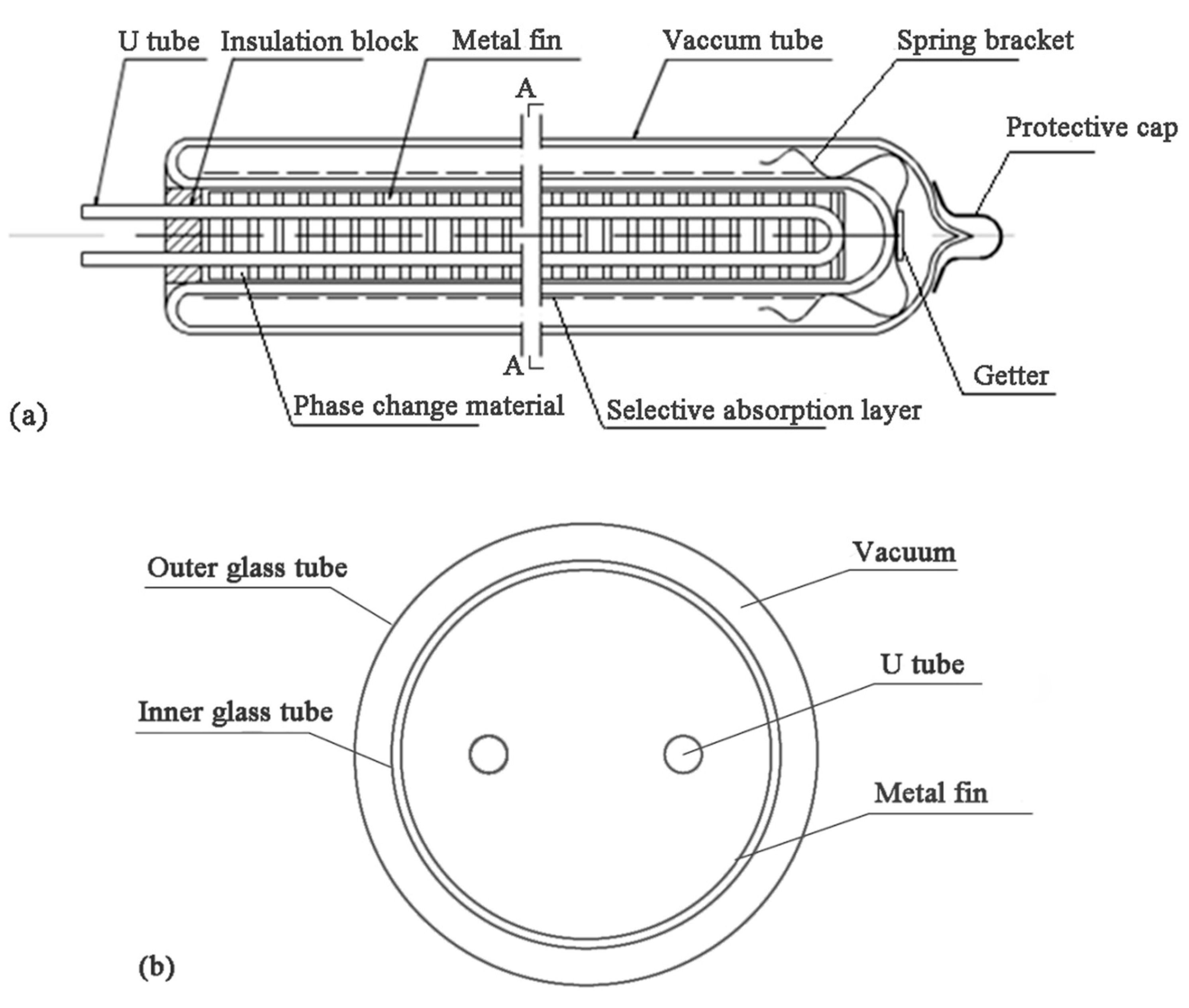
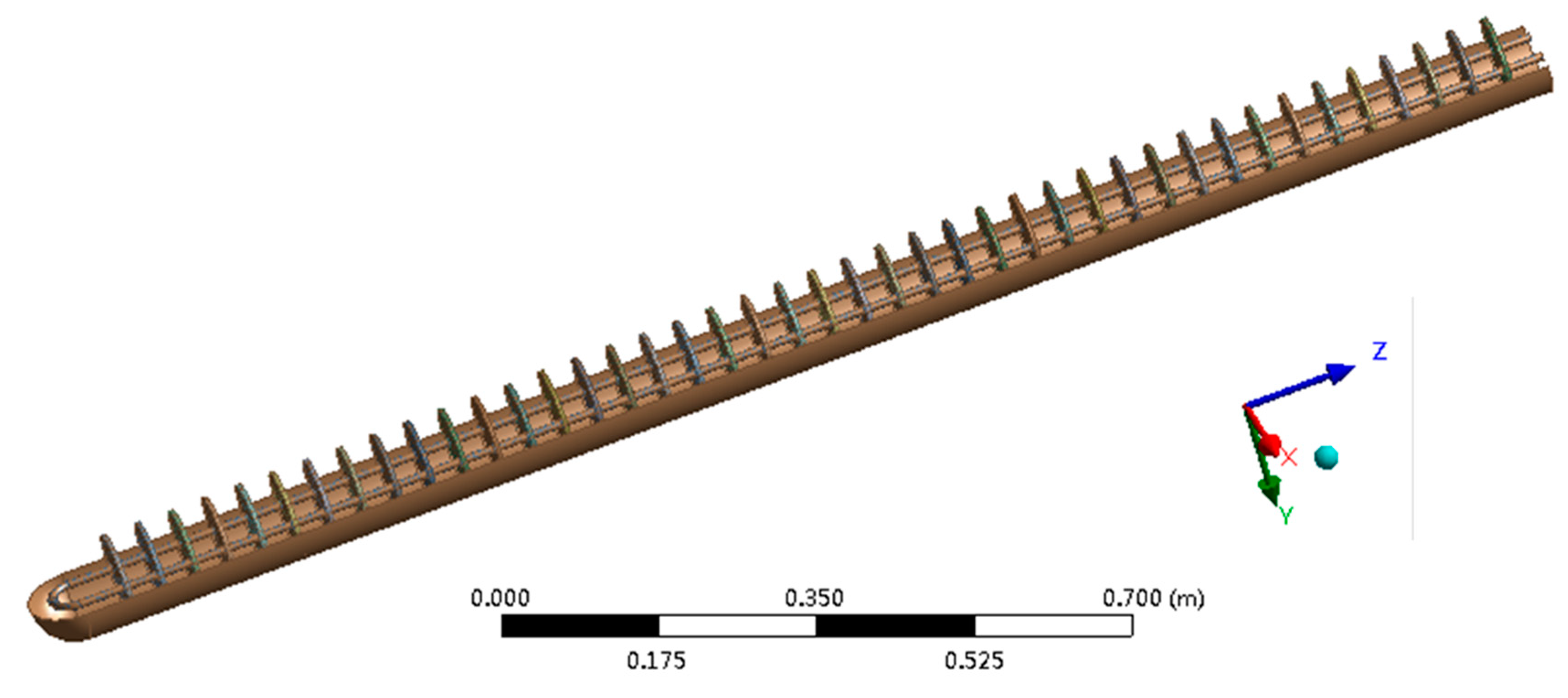
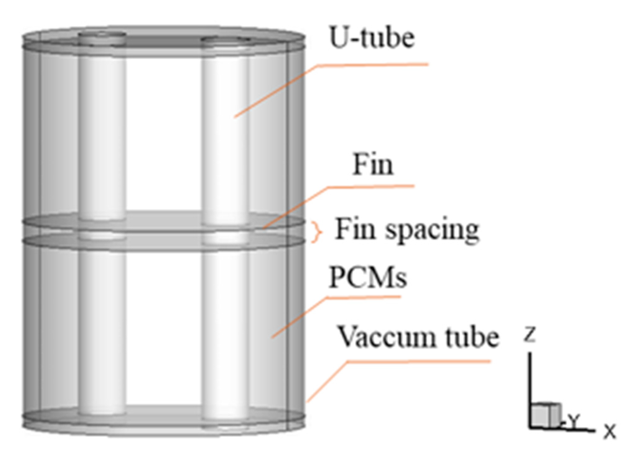
2. Problem Description

Figure 1 is the schematic of a phase change energy storage solar vacuum tube. It is mainly made up with a U tube, vacuum tube, phase change material and metal fins. Figure 1a shows details about the vacuum tube. The U tube is made of copper, which is placed inside the vacuum glass tube. Water flows through the U tube and heat is transferred to the water, hence increasing the water temperature. To enhance the heat transfer efficiency, metal fins are uniformly distributed outside the U tube. Paraffin is used as a phase change material and is filled in the vacuum tube. Figure 1b is the schematic of an A-A cross-section of the vacuum tube. The proposed solar vacuum tube (as shown in Figure 1) is supposed to store energy and enhance the phase change heat transfer efficiency due to the existence of paraffin and metal fin.
To study phase change characteristics of the solar vacuum tube, the structure of the solar vacuum tube is simplified. The vacuum part of the vacuum tube is neglected, that is, the vacuum tube is recognized as a tube with 0 thicknesses. Meanwhile, the thickness of the U tube is neglected due to the relatively high conductivity of the material (copper). Figure 2 is the mathematical model of a phase change energy storage solar vacuum tube; its tilt angle is 32°.
The length of the phase change energy storage solar vacuum tube is 1800 mm. The diameter of the glass tube is 105 mm. The U-shaped copper tube is placed in the vacuum glass tube and is coaxial with the solar vacuum tube. The inner diameter of the U tube is 10 mm. The distance between the two parallel copper tubes is 50 mm. The curvature radius of the bottom bent part of the U tube is 25 mm. The metal fin is made of aluminum with a thickness of 4 mm, and the space between the adjacent fins is 40 mm.

3. Macroscopic Governing Equations

3.1. Macroscopic Governing Equations

In order to establish the macroscopic governing equations, the following assumptions are made:
(I)
A mushy zone exists during the melting of paraffin. Therefore, three phase zones exist during the melting of paraffin, which are; solid zone, liquid zone, and mushy zone.
(II)
The physical properties of paraffin in the solid phase and the liquid phase are constant. The physical properties of paraffin in the mushy state change linearly with the temperature.
(III)
The liquid paraffin is a Newtonian fluid.
Based on the above assumptions, the control equations for the present problem are as follows:
Continuity equation:
( ρ f v ) = 0
where ρf is the density of the PCM liquid and v is the velocity of the liquid PCM.
Momentum equation (the Theory Guide of Fluent software, part 24):
( ρ f v ) t + ( ρ f v v ) = P + Δ ( μ v ) + S
where t is the time, k is the heat conductivity, and μ is the dynamic viscosity. The source term S in the momentum equation is expressed as:
S = ( 1 β ) 2 β 2 + ε A m u s h y v + S b
where β is the liquid fraction, which represents the ratio of the liquid phase to the whole PCM during the melting/solidification processes, ε is a small calculation constant to avoid the denominator being zero, and ε = 0.0001. Amushy is a constant of the mushy zone, which is in the range of 10−4–10−7. Sb is the buoyancy term, which is expressed as:
S b = ρ α g ( T T r e f )
where α is the volume expansion coefficient of the phase change material and Tref is the reference temperature.
Energy equation:
ρ f H t = k 2 T .
The enthalpy method is used to solve the solid-liquid phase change problem. Where, H is the enthalpy of the PCM. It can be expressed as:
H = h + Δ H
h = h r e f + T r e f T c p d T
Δ H = β L
where, href is the heat enthalpy of the PCM at Tref and L is the latent heat of the PCM for the solid-liquid phase change. The value of the liquid phase rate, β, during the phase change varies between [0, 1], defined as follows:
β = { 0 T < T s o l i d T T l i q u i d T s o l i d T l i q u i d T s o l i d < T < T l i q u i d 1 T > T l i q u i d
where the PCM temperature, T, in the mushy zone changes between Tsolid and Tliquid. Tsolid and Tliquid are the low and high limit levels of the mushy zone temperature, respectively. In this paper, Tref = Tsolid.

3.2. Boundary Conditions

The heat transfer of the solar energy collection system during the energy storage process is simulated. The vacuum tube is under non-operating condition, that is, water circulates in the U-type copper tube at natural convection state. During simulation, the thickness of the copper tube wall is neglected. The copper tube wall is set as coupled (fluid-solid coupling wall). The upper surface of the collection tube receives solar radiation, and the heat flux density changes with time. The effective energy, Qu, absorbed by the collection tube is imported into FLUENT by the UDF method. The calculation of Qu can be found in Appendix A. The temperature boundary condition of the upper surface is set as User-defined-flux.

3.3. Parameter Settings

The physical property parameters of the material in the simulation is given by the paraffin producer. The details are shown in Table 1.
It is assumed that the physical property parameters of paraffin change linearly with the temperature during the phase change melting process. When the paraffin temperature is 328–334 K, the main physical property parameters satisfy the following equation. The equations are fitting formulas based on the parameters in Table 1.
Density:
ρ = 4412.9 10.9 T ( 328 K T 334 K )
Specific heat:
C p = 25077.6 66.67 T ( 328 K T 334 K )
Heat conductivity:
k = 11.2724 0.0333 T ( 328 K T 334 K )
In the paper, taking Nanjing (China) for example, the inclination angle of the vacuum collection tube is set at 32° (the geographic latitude value of Nanjing). The time step is set at 0.6 s. The initial temperature of the paraffin is set at 300 K.

4. Results and Discussion

4.1. Solid-liquid Phase Change Characteristics

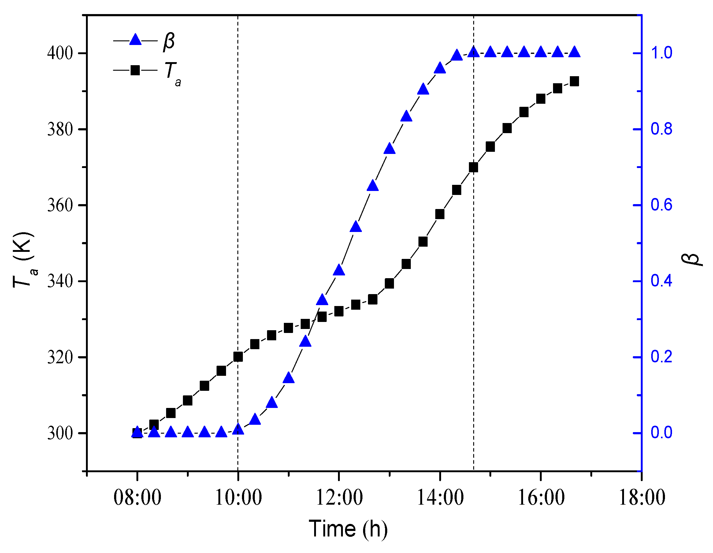
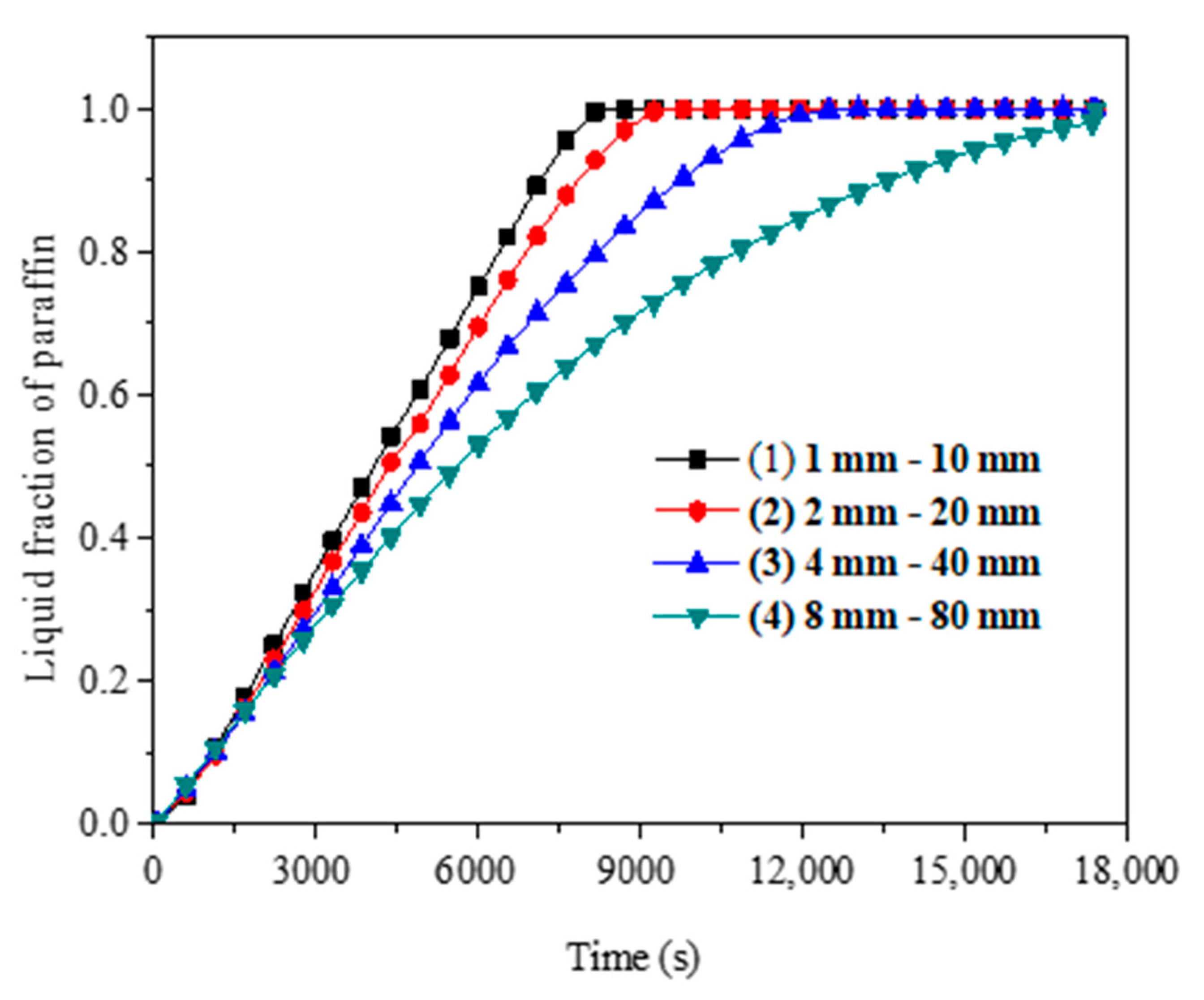
4.1.1. Dynamic Change of Average Temperature and Liquid Fraction

The simulation process was from 8:00 to 17:00. The dynamic change of the average temperature (Ta) and the liquid fraction (β) of the paraffin in the vacuum collection tube are shown in Figure 3. The paraffin experiences a process from solid phase to solid-liquid two-phase to liquid phase. As shown in Figure 3, the overall average temperature of the paraffin increases from 300 K to 392 K in one day, the paraffin temperature increases due to heating from solar energy.
In the first stage (8:00 am to 10:00 am), the average temperature of the paraffin changes rapidly, and the liquid fraction is 0. This is because the paraffin is in solid phase at this time. The storage energy in the paraffin is in a sensible heat state.
When the average paraffin temperature reaches 320 K (around 10:00 am), part of the paraffin begins to melt. During the melting process, both sensible heat and latent heat coexist during the energy storage process of the paraffin. However, the latent heat of the paraffin has an important effect on the average temperature. During the paraffin phase change process, the temperature changes very slowly. Meanwhile, the liquid fraction changes with time.
After 14:00, the liquid fraction of the paraffin is close to 1, indicating that the paraffin is completely melted into liquid. Therefore, the heat storage process is pure sensible heat storage. From the ascending curve of the average temperature of the paraffin, it can be seen that, after liquefaction, the temperature increase rate of the whole paraffin (23 °C in 2 h) is a little higher than that of 8:00–10:00 (20 °C in 2 h). There are two main reasons for this. First, because of the difference between the physical properties of the solid and liquid paraffin, the specific heat capacity of solid paraffin is higher than that of liquid paraffin. If the same heat is absorbed, the temperature of solid paraffin rises more slowly. Second, the natural convection affected by gravitational force enhances the heat transfer within paraffin after the paraffin is completely melted into liquid.

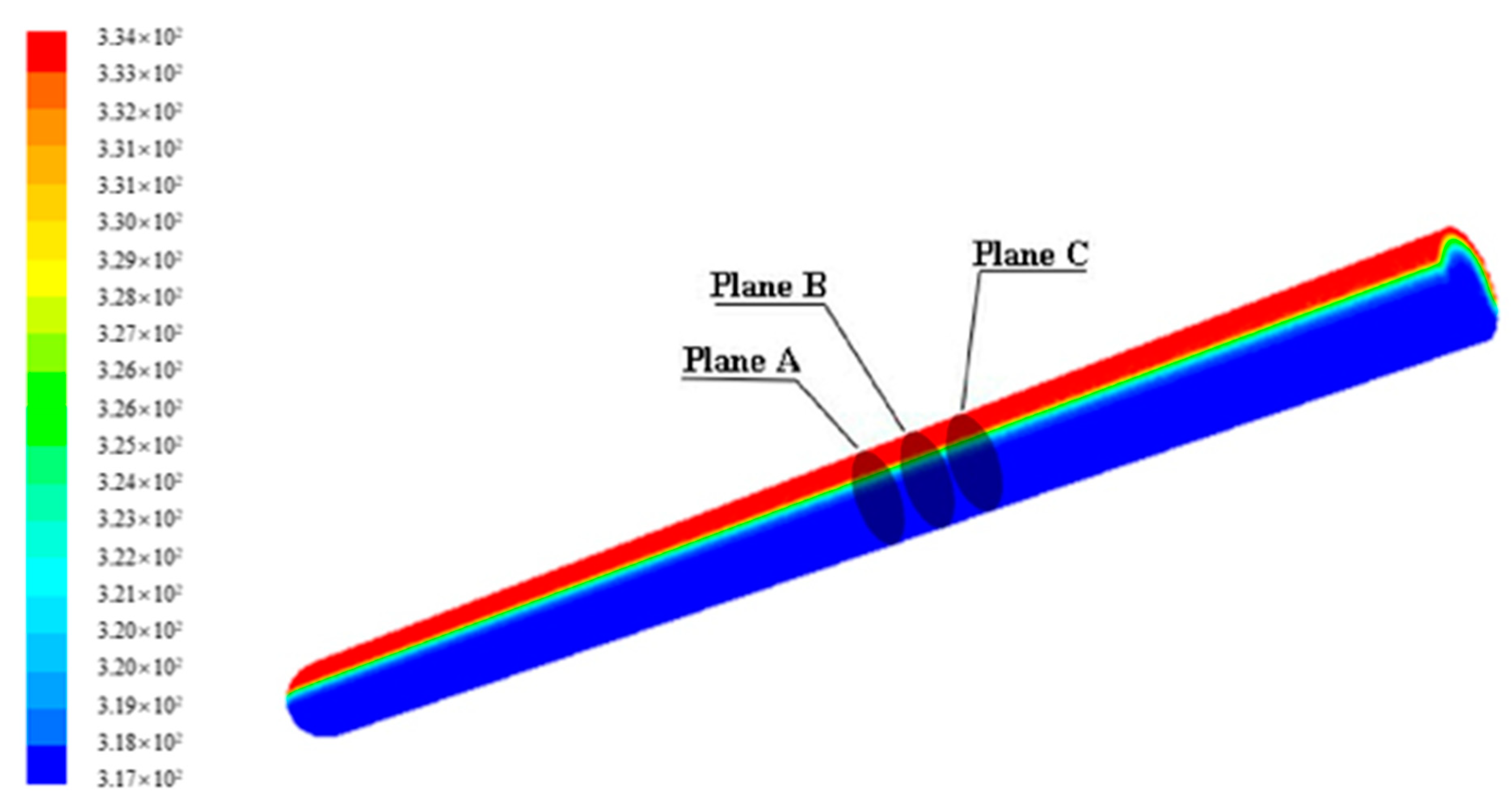
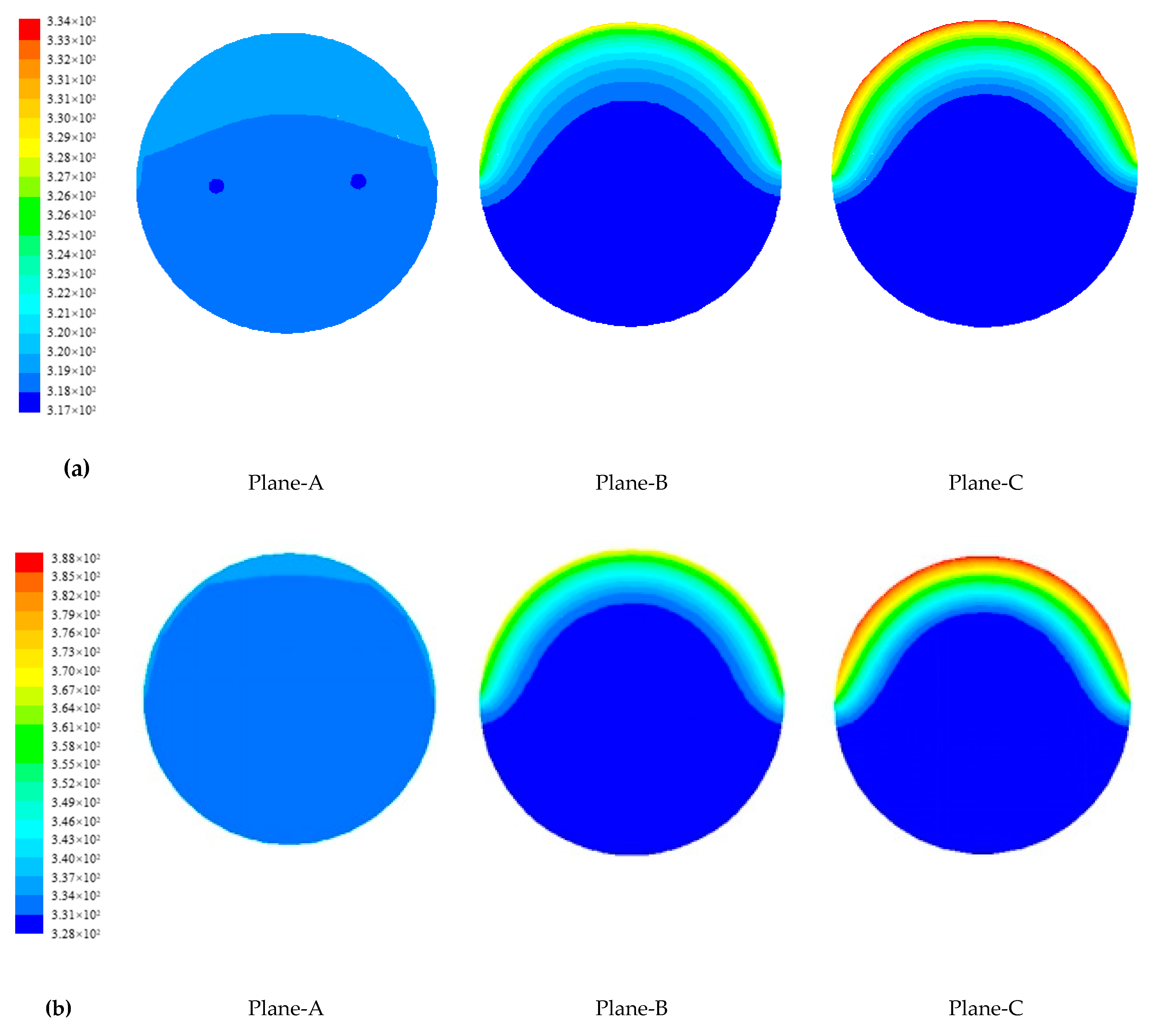
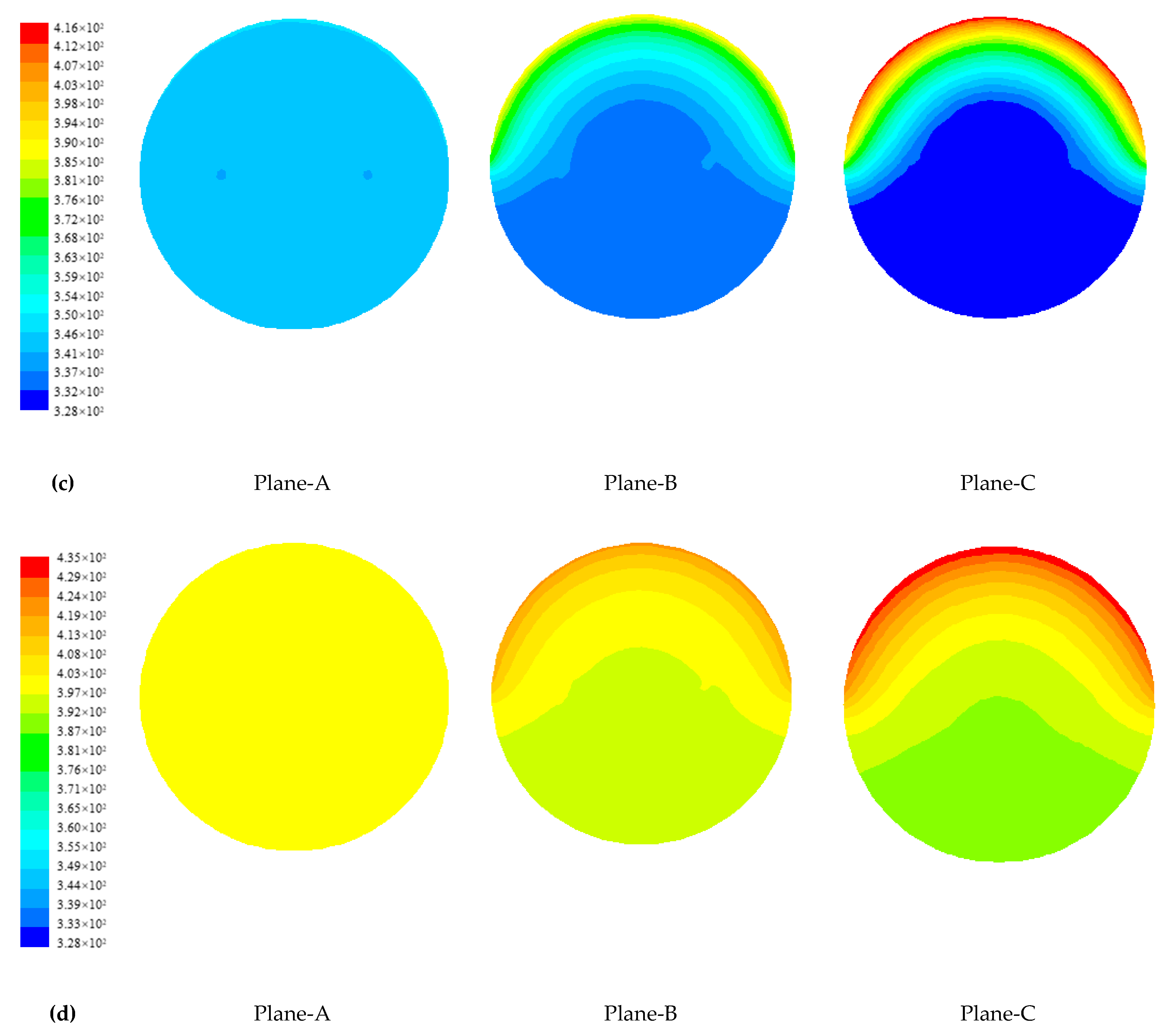
4.1.2. Temperature Distribution of Paraffin

At 10:00 am, the average paraffin temperature in the solar energy vacuum tube is 320 K and the temperature distribution is relatively uniform. The maximum temperature in the tube is 334 K, and the lowest temperature is 317 K. At this time, the liquid fraction is 0.0075, and a very small amount of paraffin near the radiant heat flow boundary has melted. The contour of temperature distribution of the paraffin is shown in Figure 4.
In order to describe the internal heat transfer of the paraffin more clearly and intuitively, the temperature distribution of the paraffin and the phase interface at three different locations are studied. The three locations are: Plane-A (Z = 834.5, 1 mm away from the central metal fin), Plane-B (Z = 841.5, 8 mm away from the central metal fin), Plane-C (Z = 853.5, in the middle of two fins, 20 mm away from the central metal fin). The detailed temperature distribution is shown in Figure 5.
As shown in Figure 5a, at 10:00, the maximum temperature of Plane-A is about 320 K, the minimum temperature is 318.5 K, the maximum temperature difference is 1.5 K, and the temperature distribution is very uniform. At the same time, the maximum temperature of Plane-B is 325 K and the minimum temperature is 317 K, with a maximum temperature difference of 8 K. Meanwhile, the maximum temperature of Plane-C is 334 K and the minimum temperature is 317 K, with a maximum temperature difference of 17 K. It shows that the closer the paraffin in the vacuum tube is to the fin, the more uniform the temperature distribution is. Similar phenomena are shown in Figure 5b–d (the temperature profile of sections at 12:00, 13:00, and 15:00).
At 12:00, the average temperature of the paraffin is 334.5 K and the liquid fraction is 0.4257 (as shown in Figure 3). At this time, the temperature difference in Plane-A is small and the paraffin is in liquid phase. However, the maximum temperature of Plane-C is 388 K and the minimum temperature is 328 K, which means that the temperature difference has reached 60 K. It implies that the fin has a great effect on the temperature distribution in paraffin. With the application of fins, the thermal property of fins could promote phase change heat transfer in paraffin.
At 13:00, the body average temperature of the paraffin is 337.1 K (as shown in Figure 3), which is only 2.6 K larger than that at 12:00. It can be seen from Figure 5c that the paraffin at Plane-A and Plane-B have all melted while the paraffin at Plane-C is not well melted. This indicates that latent heat storage is still the main heat storage form. At 15:00, the average temperature of the paraffin is 371 K, the liquid fraction is 0.99 (as shown in Figure 3), and the paraffin in the vacuum tube has been almost melted (as shown in Figure 5d).

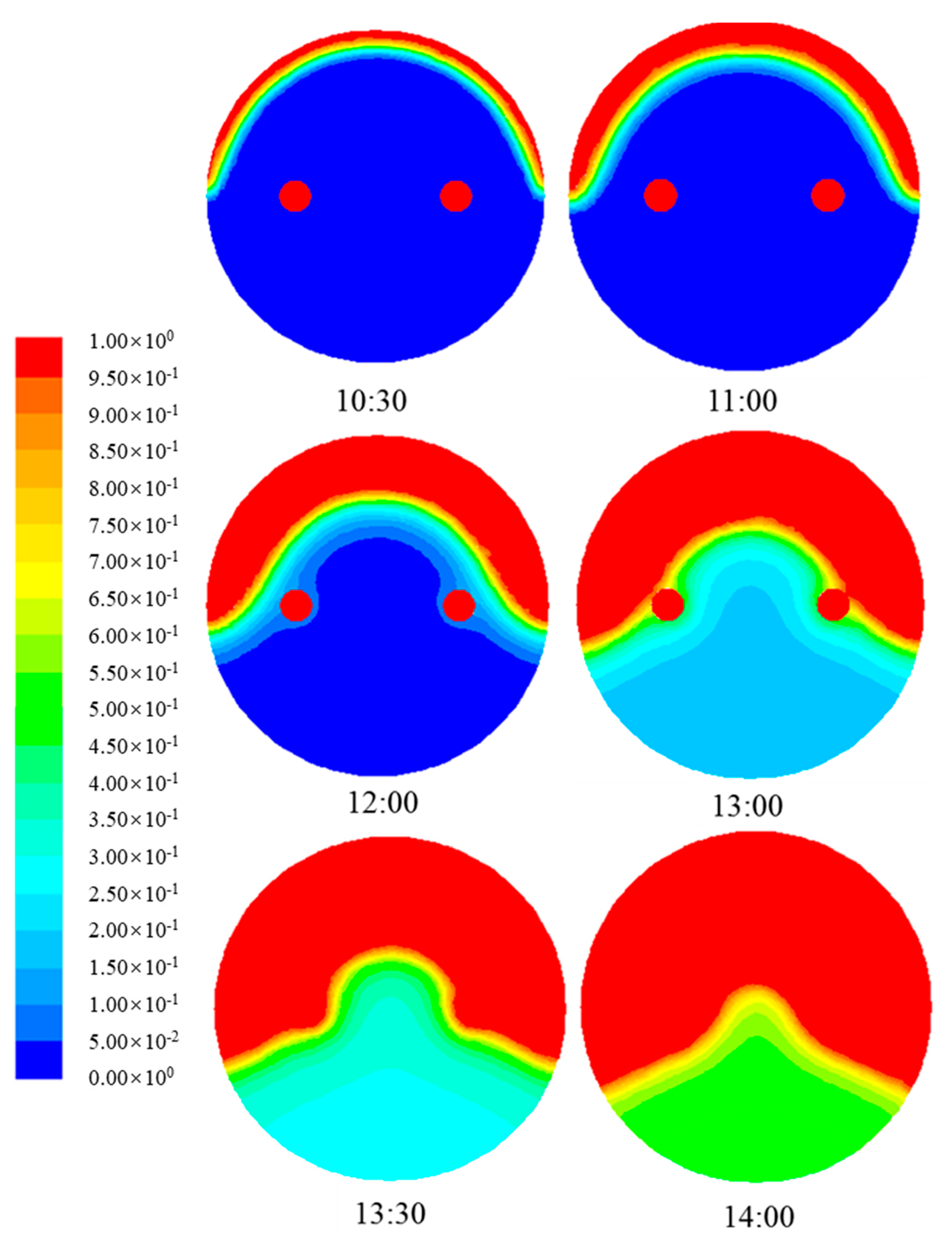
4.1.3. Evolution of Phase Change Interface of Paraffin

From Figure 3, it can be seen that between 10:00 and 14:20 the paraffin melts, that is, the paraffin is in the mushy zone. The phase interface at location Plane-C is investigated to show the solid-liquid phase interface change. Figure 6 shows the phase interface changes of Plane-C at different times (10:30, 11:00, 12:00, 13:00, 13:30, and 14:00). As time passes, the liquid part increases. The liquid-solid interface moves from the top to the bottom.

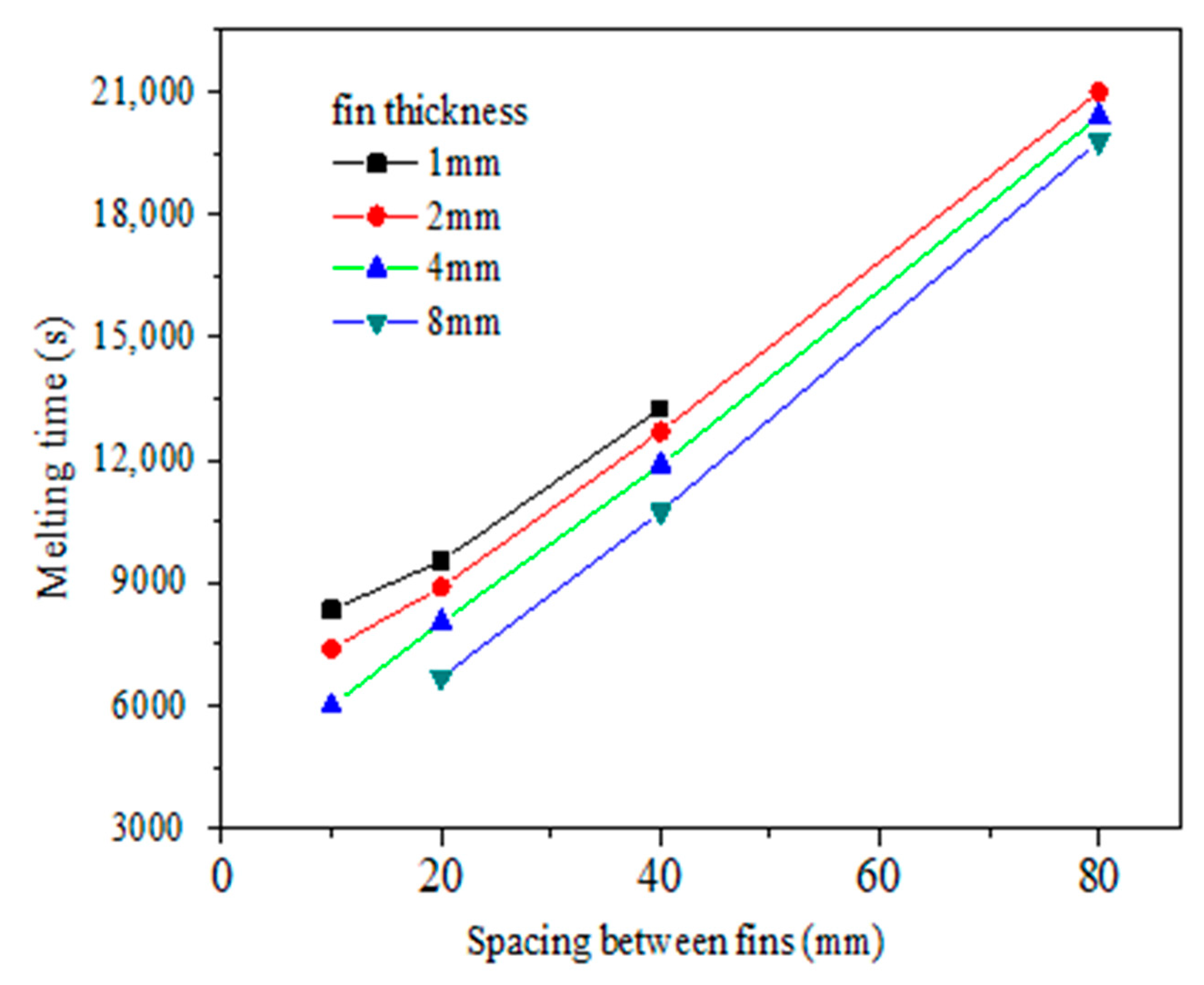
4.2. Optimization Analysis of Fin Structure Parameters in Vacuum Tube

It can be concluded from the above numerical results that the radial fins in the U-shaped copper tube could enhance the heat transfer in the vacuum collection tube and accelerate the melting process of paraffin. However, the fin thickness and fin spacing not only influence the heat transfer enhancement, but also has an effect on the volume of the phase change heat storage material and the machining process difficulty. Therefore, a reasonable fin arrangement is essential. The thermal storage simulation analysis on the vacuum tube with different fin thicknesses (1 mm, 2 mm, 4 mm, 8 mm) and fin spacing (10 mm, 20 mm, 40 mm, 80 mm) is studied in this part. When the fin spacing is 80 mm and the fin thickness is 1 mm, the space for the paraffin is very large. It can be inferred that the effect of the fin on phase change heat transfer is weak. Similarly, when the fin spacing is 10 mm and the fin thickness is 8 mm, the space for the paraffin is too small. Therefore, the aforementioned two cases are not considered in this study.
Because, with the large number of model grids of a whole glass tube, the calculation time is too long, so the model has been simplified, as shown in Figure 7. A length of 80 mm of the vacuum tube is taken as the heat storage simulation unit and simulated.
As the purpose of the simulation in this part is to compare the influence of fin structure on the heat transfer process in the SVT, the boundary condition is simplified in the simulation. The solar radiation heat flow is set at a constant value of 1000 W/m2. The initial temperature of the paraffin is 325 K, and the heat loss of the vacuum collector to the surrounding environment is neglected. The simulation results are shown in Figure 8.
The melting time of paraffin is 29,480 s in the radial direction of the U-shaped copper tube without metal fins. When inserting metal fins, it can be seen from Figure 8 that the melting time of the paraffin significantly decreases. The melting time of the paraffin decreases with the increase of fin thickness and the decrease of spacing between the fins. As the spacing between the fins increases, the gap between the melting time of different fin thicknesses becomes smaller. When the fin spacing reaches 80 mm, the melting time of the paraffin with a fin thickness of 2 mm, 4 mm, and 8 mm is 21,000 s, 20,400 s, and 19,800 s, respectively. That is, the fin thickness has little effect on the heat transfer at large spacing. In addition, when the fin thickness is 2 mm, the melting time of the paraffin with a fin spacing of 10 mm, 20 mm, 40 mm, and 80 mm is 7400 s, 8900 s, 12,700 s, and 21,000 s, respectively. It can be seen that the melting time of the paraffin with a fin spacing of 80 mm is almost three times that of the fin with a spacing of 10 mm. It can be concluded that the effect of fin spacing on the overall heat transfer performance of a phase change energy storage tube is larger than that of fin thickness.
Considering the same fin volume, the combination of fin thickness and fin spacing is different. Figure 9 shows the liquid fraction change of the paraffin in the vacuum tube. Four cases are considered here: (1) 1 mm fin thickness and 10 mm fin spacing, (2) 2 mm fin thickness and 20 mm fin spacing, (3) 4 mm fin thickness and 40 mm fin spacing, and (4) 8 mm fin thickness and 80 mm fin spacing. It can be concluded from Figure 9 that the liquid fraction of the paraffin increases quicker with smaller fin thickness and smaller fin spacing. Combining the results from Figure 8 and Figure 9, it is concluded that when designing fin structure in the SVT, it is better to choose small fin spacing and large fin thickness.

5. Conclusions

In this paper, a new kind of solar vacuum tube with phase change energy storage is introduced. The heat transfer process of the solar energy collection system during the energy storage process is simulated. Optimization of fin structure in the vacuum tube is analyzed. The results are concluded as follows:
(1)
As the paraffin gets heat through the daytime, the paraffin experiences a process from solid phase to solid-liquid two phase to liquid phase. Meanwhile, paraffin temperature increases during the daytime. In solid-liquid two phase, paraffin temperature increases slowly as latent heat storage plays an important role during phase change.
(2)
The metal fin has a great effect on the phase change heat transfer process of paraffin in SVTs. The closer the paraffin is to the fins, the more uniform the paraffin temperature is and the sooner the paraffin melts.
(3)
The metal fin structure and arrangement are major factors that affect the paraffin melting time. The melting time of paraffin decreases with the increase of fin thickness and the decrease of fin spacing. With constant fin volume, it is better to choose a smaller fin thickness and smaller fin spacing.
The proposed solar vacuum tube integrating with phase change material could improve the heat transfer performance for solar energy storage and could have potential applications in solar energy storage systems.

Author Contributions

Data curation, J.S. and L.S.; funding acquisition, Z.C.; investigation, H.X.

Funding

This research was funded by the National Key R&D Program of China, grant number 2016YFC0700200; the Research Funds of Key Laboratory of Heating and Air Conditioning, and the Education Department of Henan Province.

Conflicts of Interest

The authors declare no conflict of interest.

Nomenclature

ρfDensity of the PCM liquid [kg.m−3]
gGravitational acceleration [m.s−2]
v Velocity of liquid PCM [m.s−1]
tTime [s]
kHeat conductivity [W.m−1.K−1]
μDynamic viscosity [kg.m−1.s−1]
SSource term in the momentum equation [kg.m−2.s−2.K]
βRatio of the liquid phase to the whole PCM [kg.kg−1]
εSmall calculation constant to avoid the denominator to be zero [-]
AmushyConstant of mushy zone [-]
SbBuoyancy term [kg.m−2.s−2.K]
αVolume expansion coefficient of phase change material [-]
TrefReference temperature [K]
HEnthalpy of PCM [kJ.kg−1]
hrefHeat enthalpy of PCM at Tref [kJ.kg−1]
TsolidLow limit level of the mushy zone temperature [K]
TliquidHigh limit level of the mushy zone temperature [K]
TPCM temperature [K]

Appendix A

The solar radiation passes through the outer wall of the transparent vacuum glass tube and reaches the outer side of the inner glass. The heat converted from the radiation energy is absorbed by the selective absorption coating. Part of the heat transfers to the phase change heat storage material in the SVT, and the other is lost to the surrounding environment through heat radiation/conduction/convection [22,23].
(1) According to the energy conservation principle, the useful energy obtained by the solar vacuum collector tube in unit time is equal to the solar radiation energy absorbed by the collector tube minus the heat loss to the surrounding environment by the collector tube. It is expressed as follows:
Q u = Q 0 Q L
where Qu is the useful energy obtained by the collector tube, W, QL is the heat loss of the collector tube to the surroundings in the same period, W. Q0 is the solar radiation energy absorbed by collector tubes in the same period, W, which can be written as follows:
Q 0 = A e I θ ( τ γ ) e
where Ae is the effective area that can collect solar energy, m2, Iθ is the solar radiation intensity on the inclined surface of the collector, W/m2, and (τγ)e is the product of effective transmissivity and absorptivity of the heat absorbing surface.
Considering that the reflection of the vacuum glass tube to the light varies with the incident angle, the effective area that can collect solar energy is taken as 1.43 times that of the projection area of the absorption glass tube, that is:
A e = 1.43 A p
A p = D L
where D is the outer diameter of the SVT and L is the length of the SVT.
(2) The heat loss to the surrounding area by the collector is related to the surface temperature, ambient temperature, and the heat absorbing area. The heat loss, QL, can be calculated by the following formula:
Q L = A a U L ( T p T a )
where Aa is the area of the SVT, Tp is the surface temperature of the SVT, Ta is the ambient temperature, and UL is the total heat loss coefficient.

References

  1. Sun, L.; Shen, J.; Hua, Q.; Lee, K.Y. Data-driven oxygen excess ratio control for proton exchange membrane fuel cell. Appl. Energy 2018, 231, 866–875. [Google Scholar] [CrossRef]
  2. Yin, Z. Development of solar thermal systems in China. Sol. Energy Mater. Sol. Cells 2005, 86, 427–442. [Google Scholar]
  3. Farid, M.M.; Khudhair, A.M.; Razack, S.A.K.; Al-Hallaj, S. A review on phase change energy storage: Materials and applications. Energy Convers. Manag. 2004, 45, 1597–1615. [Google Scholar] [CrossRef]
  4. Oró, E.; de Gracia, A.; Castell, A.; Farid, M.M.; Cabeza, L.F. Review on phase change materials (PCMs) for cold thermal energy storage applications. Appl. Energy 2012, 99, 513–533. [Google Scholar] [CrossRef]
  5. Xiao, X.; Zhang, P.; Li, M. Experimental and numerical study of heat transfer performance of nitrate/expanded graphite composite PCM for solar energy storage. Energy Convers. Manag. 2015, 105, 272–284. [Google Scholar] [CrossRef]
  6. Mahdi, J.M.; Nsofor, E.C. Solidification enhancement of PCM in a triplex-tube thermal energy storage system with nanoparticles and fins. Appl. Energy 2018, 211, 975–986. [Google Scholar] [CrossRef]
  7. Pizzolato, A.; Sharma, A.; Maute, K.; Sciacovelli, A.; Verda, V. Design of effective fins for fast PCM melting and solidification in shell-and-tube latent heat thermal energy storage through topology optimization. Appl. Energy 2017, 208, 210–227. [Google Scholar] [CrossRef]
  8. Kabeel, A.E.; Khalil, A.; Shalaby, S.M.; Zayed, M.E. Experimental investigation of thermal performance of flat and v-corrugated plate solar air heaters with and without PCM as thermal energy storage. Energy Convers. Manag. 2016, 113, 264–272. [Google Scholar] [CrossRef]
  9. Al-Hinti, I.; Al-Ghandoor, A.; Maaly, A.; Naqeera, I.A.; Al-Khateeb, Z.; Al-Sheikh, O. Experimental investigation on the use of water-phase change material storage in conventional solar water heating systems. Energy Convers. Manag. 2010, 51, 1735–1740. [Google Scholar] [CrossRef]
  10. Canbazoğlu, S.; Şahinaslan, A.; Ekmekyapar, A.; Aksoy, Ý.G.; Akarsu, F. Enhancement of solar thermal energy storage performance using sodium thiosulfate pentahydrate of a conventional solar water-heating system. Energy Build. 2005, 37, 235–242. [Google Scholar] [CrossRef]
  11. Belmonte, J.F.; Izquierdo-Barrientos, M.A.; Molina, A.E.; Almendros-Ibáñez, J.A. Air-based solar systems for building heating with PCM fluidized bed energy storage. Energy Build. 2016, 130, 150–165. [Google Scholar] [CrossRef]
  12. Veerappan, M.; Kalaiselvam, S.; Iniyan, S.; Goic, R. Phase change characteristic study of spherical PCMs in solar energy storage. Sol. Energy 2009, 83, 1245–1252. [Google Scholar] [CrossRef]
  13. Amina, B.; Miloud, A.; Samir, L.; Abdelylah, B.; Solano, J.P. Heat transfer enhancement in a parabolic trough solar receiver using longitudinal fins and nanofluids. J. Therm. Sci. 2016, 25, 410–417. [Google Scholar] [CrossRef]
  14. Eslamnezhad, H.; Rahimi, A.B. Enhance heat transfer for phase-change materials in triplex tube heat exchanger with selected arrangements of fins. Appl. Therm. Eng. 2017, 113, 813–821. [Google Scholar] [CrossRef]
  15. Kumar, R.A.; Babu, B.G.; Mohanraj, M. Experimental investigations on a forced convection solar air heater using packed bed absorber plates with phase change materials. Int. J. Green Energy 2017, 14, 1238–1255. [Google Scholar] [CrossRef]
  16. Ismail, K.A.R.; Alves, C.L.F.; Modesto, M.S. Numerical and experimental study on the solidification of PCM around a vertical axially finned isothermal cylinder. Appl. Therm. Eng. 2001, 21, 53–77. [Google Scholar] [CrossRef]
  17. Sheikholeslami, M.; Lohrasbi, S.; Ganji, D.D. Response surface method optimization of innovative fin structure for expediting discharging process in latent heat thermal energy storage system containing nano-enhanced phase change material. J. Taiwan Inst. Chem. Eng. 2016, 67, 115–125. [Google Scholar] [CrossRef]
  18. Lorenzini, G.; Rocha, L.A.O. Constructal design of Y-shaped assembly of fins. Int. J. Heat Mass Transf. 2006, 49, 4552–4557. [Google Scholar] [CrossRef]
  19. Tiari, S.; Qiu, S.; Mahdavi, M. Discharging process of a finned heat pipe–assisted thermal energy storage system with high temperature phase change material. Energy Convers. Manag. 2016, 118, 426–437. [Google Scholar] [CrossRef]
  20. Lohrasbi, S.; Miry, S.Z.; Gorji-Bandpy, M.; Ganji, D.D. Performance enhancement of finned heat pipe assisted latent heat thermal energy storage system in the presence of nano-enhanced H2O as phase change material. Int. J. Hydrogen Energy 2017, 42, 6526–6546. [Google Scholar] [CrossRef]
  21. Tiari, S.; Qiu, S.; Mahdavi, M. Numerical study of finned heat pipe-assisted thermal energy storage system with high temperature phase change material. Energy Convers. Manag. 2015, 89, 833–842. [Google Scholar] [CrossRef]
  22. Yin, Z.Q.; Harding, G.L.; Collins, R.E. Thermal performance of all glass coaxial vacuum tube solar collector. Sol. Energy Chin. 1997, 2, 19–20. [Google Scholar]
  23. Xi, W.H.; Wei, Y.K.; Zhang, L.Y. Practical Engineering Technology of Solar Energy; Lanzhou University Press: Lanzhou, China, 2001. [Google Scholar]
Figure 1. Schematic of a phase change energy storage solar vacuum tube. (a) Axial cross–section (b) A-A cross-section.
Sustainability 11 06960 g001
Figure 2. Mathematical model of a phase change energy storage solar vacuum tube.
Sustainability 11 06960 g002
Figure 3. Variation of Ta and β with time.
Sustainability 11 06960 g003
Figure 4. Temperature distribution in the solar energy vacuum tube at 10:00 am.
Sustainability 11 06960 g004
Figure 5. Temperature distribution of paraffin at different sections: (a) At 10:00 am, (b) at 12:00 am, (c) at 13:00 am, (d) at 15:00 am.
Sustainability 11 06960 g005aSustainability 11 06960 g005b
Figure 6. Phase interface map of Plane-C at different times.
Sustainability 11 06960 g006
Figure 7. Simplified model of the heat storage unit
Sustainability 11 06960 g007
Figure 8. Comparison of the complete melting time of different models.
Sustainability 11 06960 g008
Figure 9. Variation of the liquid fraction with different fin structure parameters.
Sustainability 11 06960 g009
Table 1. Physical property parameters of paraffin.
ItemsParaffin
Melting point (K)328–334
Latent heat (kJ·kg−1)158.2
Density
(kg·m−3)
Solid phase837.7
Liquid phase772.2
Specific heat
(J·kg−1·K−1)
Solid phase3200
Liquid phase2800
Heat conductivity
(W·m−1·K−1)
Solid phase0.35
Liquid phase0.15

