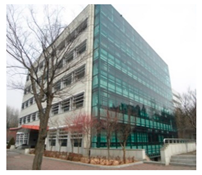
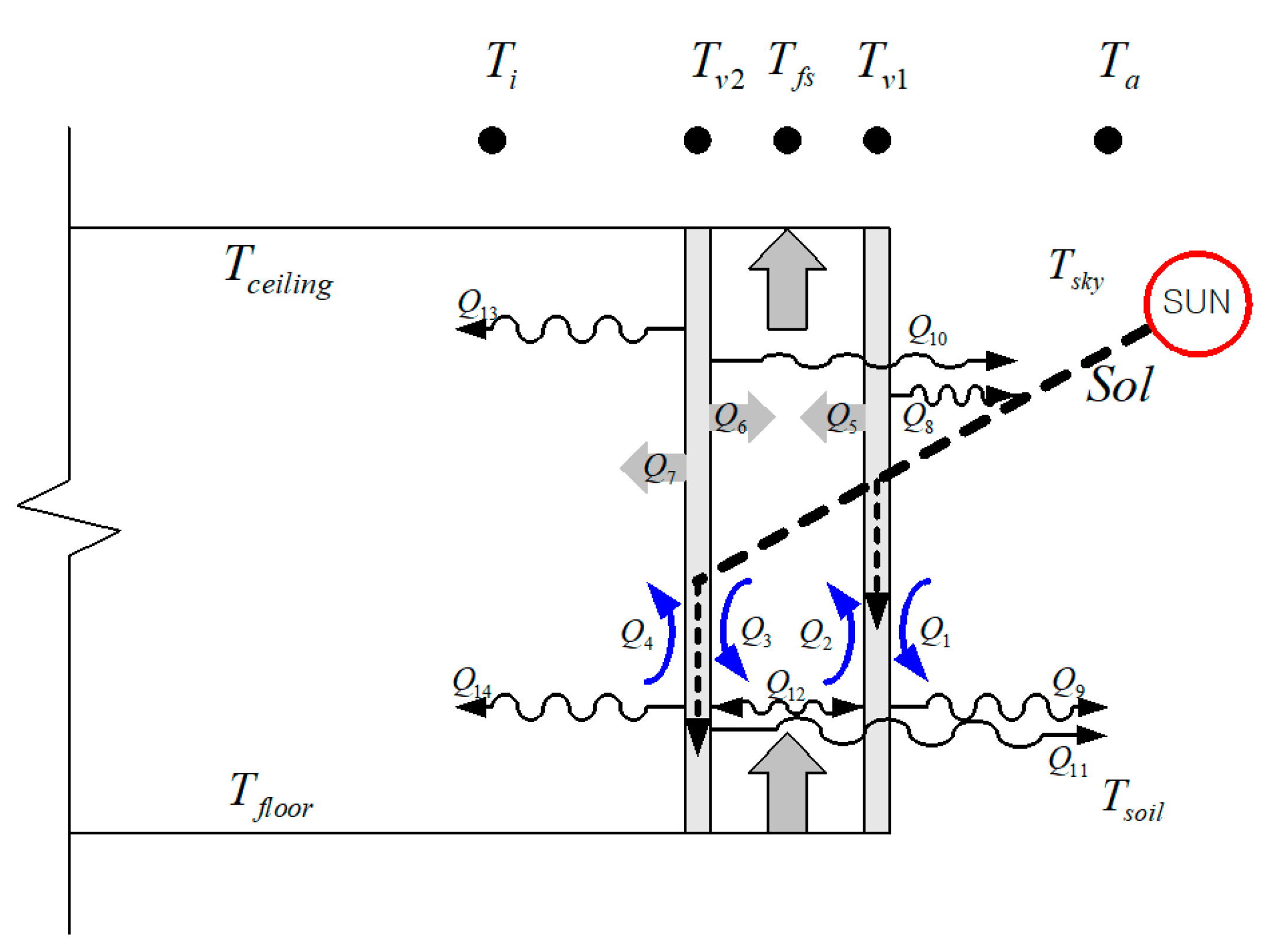
In order to propose an indoor air conditioning energy reduction plan using preheated air through the double-skin facade, this study utilized a building energy analysis simulation to be implemented on the target building and then analyzed the effects of the improvement plan for the double-skin facade. An EnergyPlus simulation model was suggested that implemented the aforementioned airflow network and analyzed the ventilation performance and energy performance according to the application of alternative plans and thermal effect.
4.1. Target Building Modeling and OA-Based System Design
Through target building modeling (baseline), the building energy analysis simulation that implemented a double-skin facade was executed. In comparison with the results of the aforementioned field measurement, the validity of the simulation model was verified.
Table 4 presents information on the building modeling. As alternative plans(ALT) for activating the internal airflow of the double-skin facade, double-skin facades with solar chimney systems were suggested, as illustrated in
Table 5.
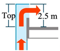
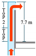
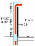
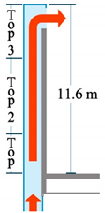
Each alternative plan replaced the outlet height (TOP) position of the baseline model. According to the installation height of the solar chimney (SC), the temperature of the inside of the double-skin facade, airflow, and indoor load were analyzed. The outlet height (TOP) of the upper side of the double-skin facade in the baseline model showed no great difference from the height of a reference floor. Therefore, this study established the following plans—the 2nd floor height of the SC (ALT1: 7.5 m), the 3rd floor height of the SC (ALT2: 11.6 m), and the thermal effect implementation for increasing the solar transmittance of the outer skin and the insolation absorptance of the inner wall (ALT3) in order to activate buoyancy-induced airflow by increasing the temperature of the SC path—and analyzed their effects.
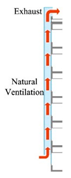
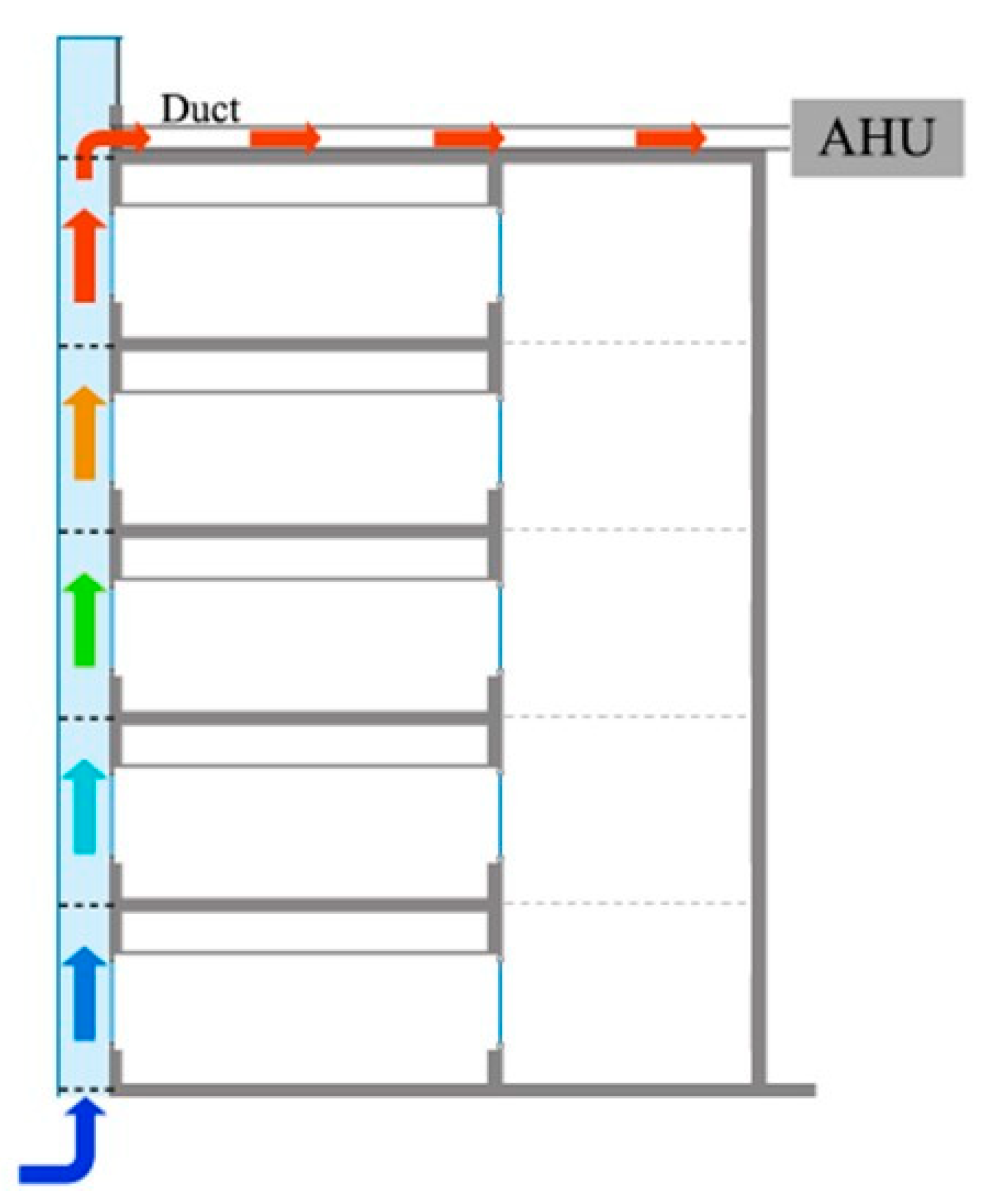
In winter, the double-skin facade secures the outer skin insulation performance of the installation side to reduce outer skin load, as shown in
Figure 10, and is used as the preheating path of OA flowing in the internal AHU (Air Handling Unit) in order to reduce the outdoor air load of air conditioning. In this study, the SC proposed to improve the heat performance of the double-skin facade increases the solar heat use capacity and OA preheating amount of the double-skin facade so that it can save more heating energy in winter. Therefore, in winter evaluation, the indoor heating load and the OA-based heat through the double-skin facade according to OA-based air volume were analyzed in each proposed alternative plan using an SC.
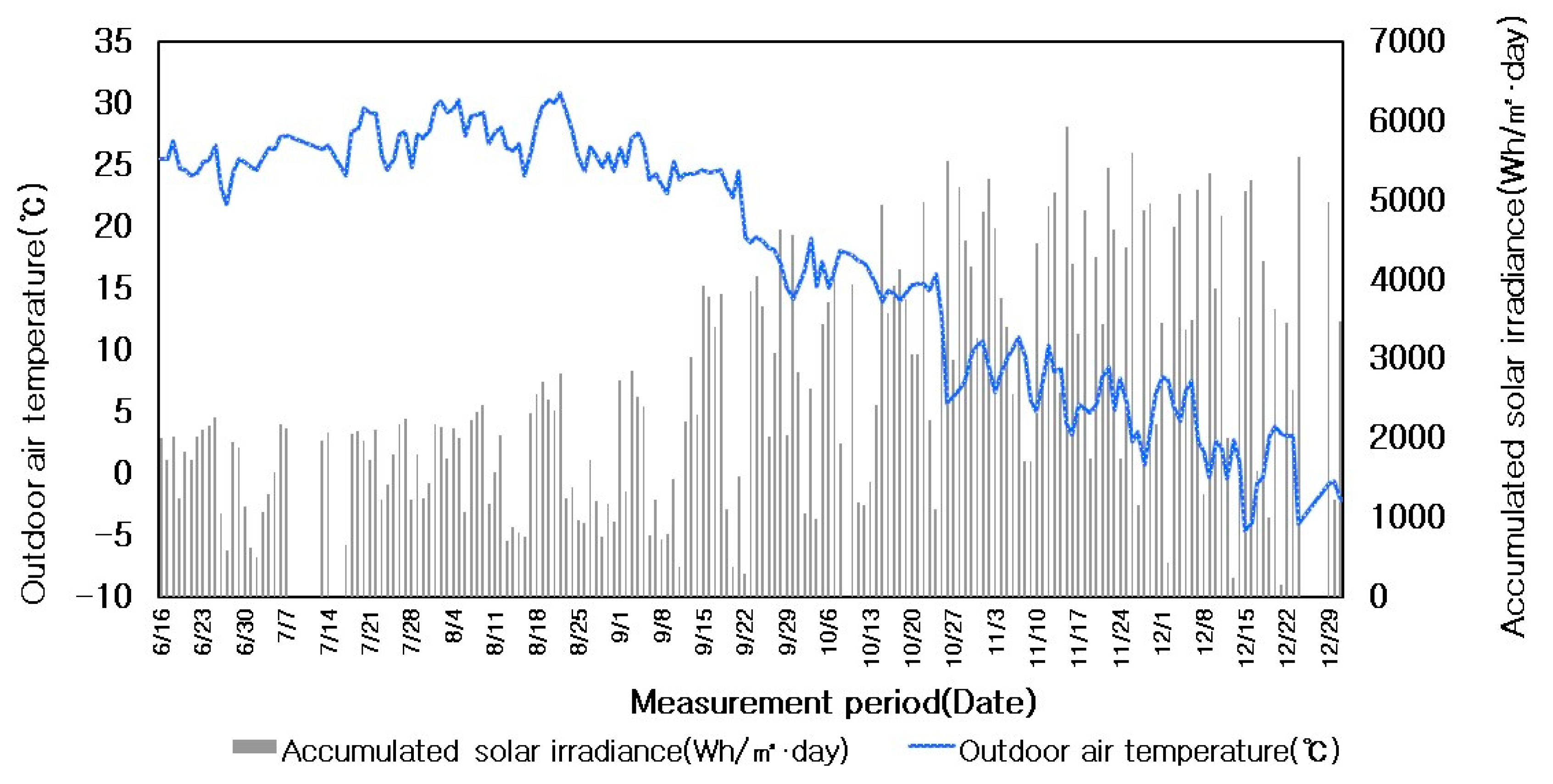
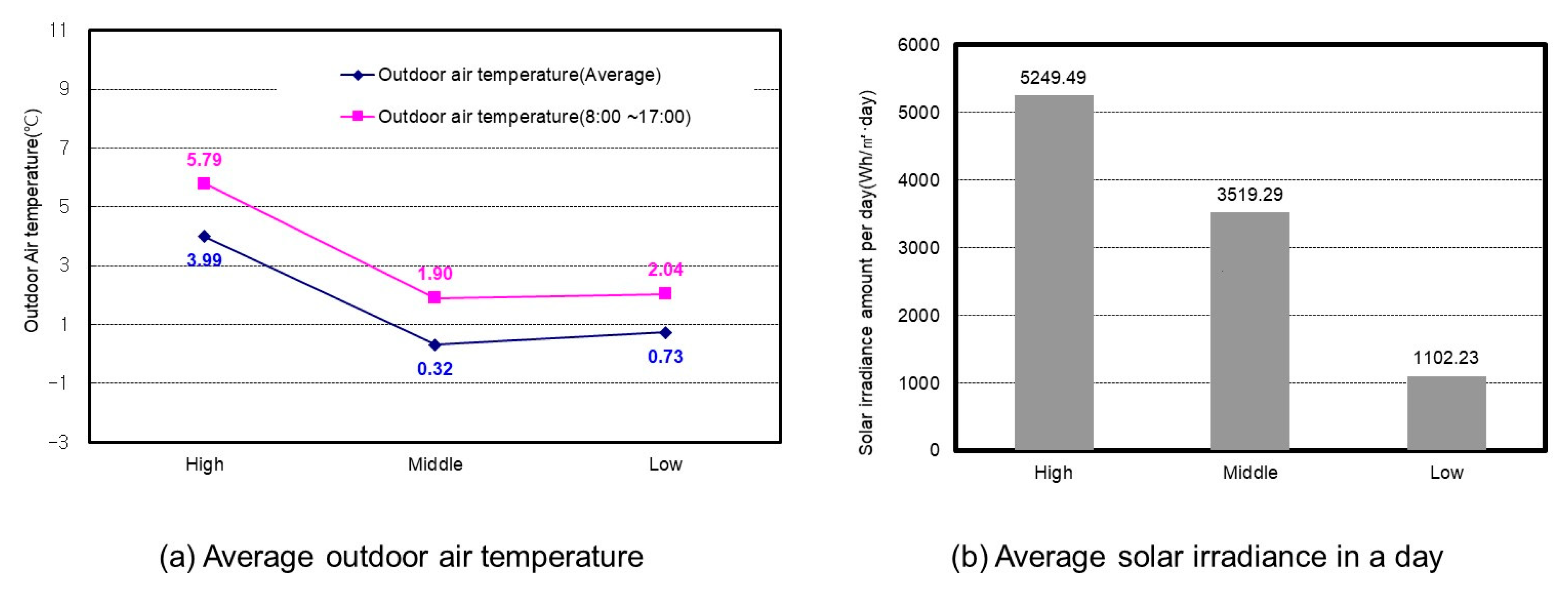
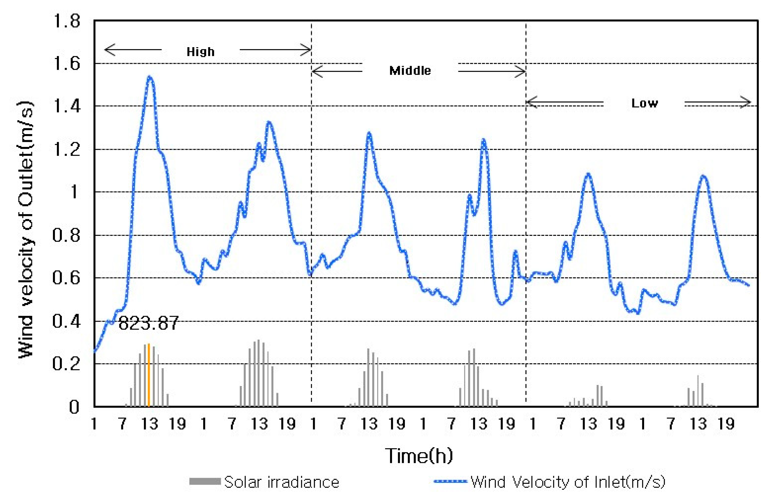
The total area of the air conditioning zone of the double-skin facade was 19,440 m3. As shown in the table, the indoor heating load and OA-based heat of the installation side of the double-skin facade were calculated according to the OA-based air volume (air changes 0.2/h–2/h) through the double-skin facade in each alternative plan with an SC. The indoor heating load and OA-based heat were added together (OA-based heat-indoor heating load), and then an appropriate air volume for the designed air change in each alternative plan was selected. On the basis of the baseline model (OA-based air volume: 9600 CMH) actually operated by the double-skin facade, the relative energy performance improvement value of the selected appropriate air volume in each alternative plan with an SC was analyzed. According to the daily accumulated irradiance of the multistory double-skin facade as the dominant influential factor on the thermal behavior of the double-skin facade, they were divided into high (4000 Wh/m2 and more), middle (2000–4000 W/m2), and low (2000 Wh/m2 or less) types. The simulation period was 95 days of heating operation from 1 November to 15 March. Heating load was calculated only in the south air conditioning zone (1F–5F) directly influenced by the double-skin facade. In terms of climate data, outdoor air temperature and humidity, measured data of solar irradiance, and wind direction and velocity data of relevant regions, which are offered by Korea Meteorological Administration, were used.
4.2. Analysis Results of the Operation Improvement Plan
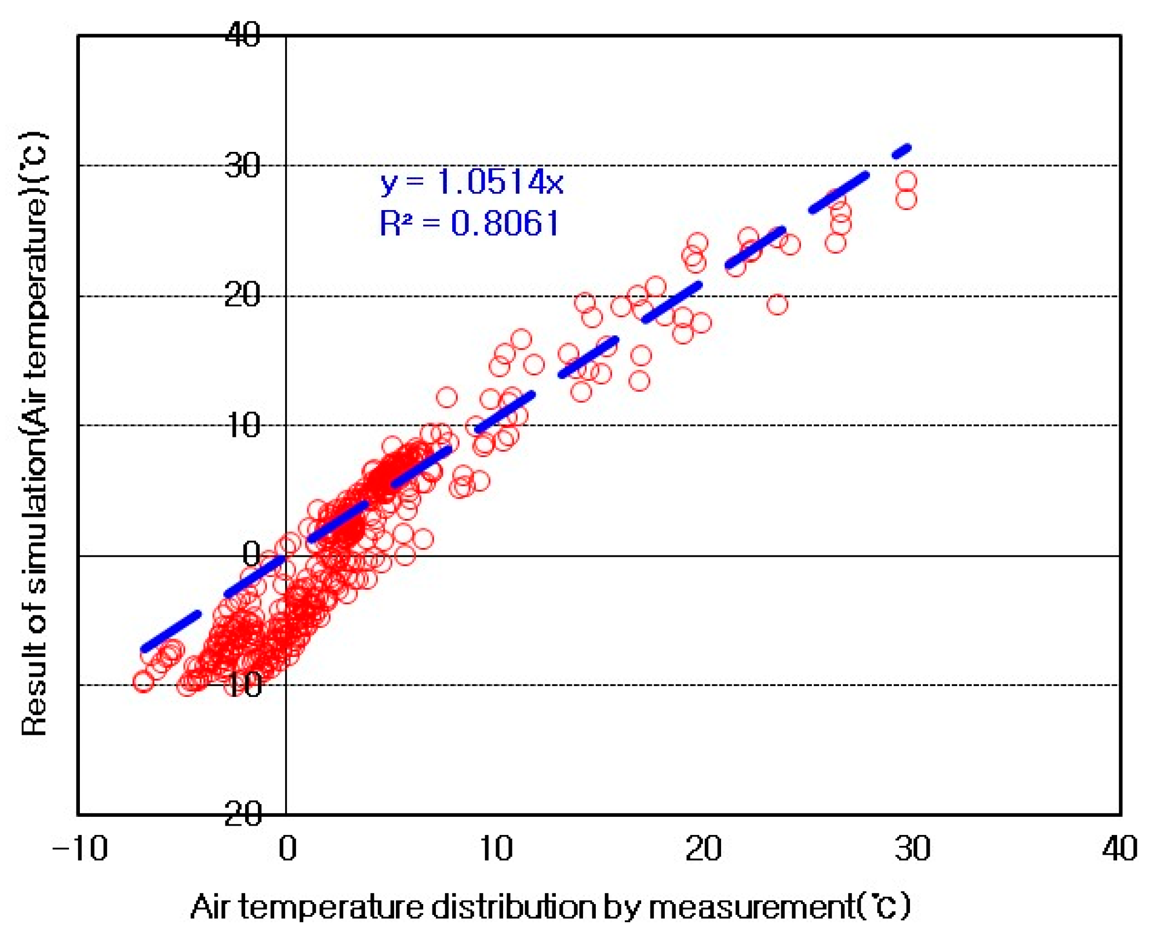
Figure 11 shows the measurement results on the x-axis and the simulation results on the y-axis in the same time zones, reacting to the same external environments on the selected analysis days, according to the solar irradiance levels in terms of cavity air temperature in order to verify the airflow network simulation baseline model in summer. Based on the linear equation with a y-intercept of ‘0’, if the coefficient of x value and R2 value are close to ‘1’, it is proved that the measurement values are highly consistent with simulation values. According to the comparison, the coefficient to x value was 0.98, and R2 was 0.96. As a result, there was a considerably high level of consistency.
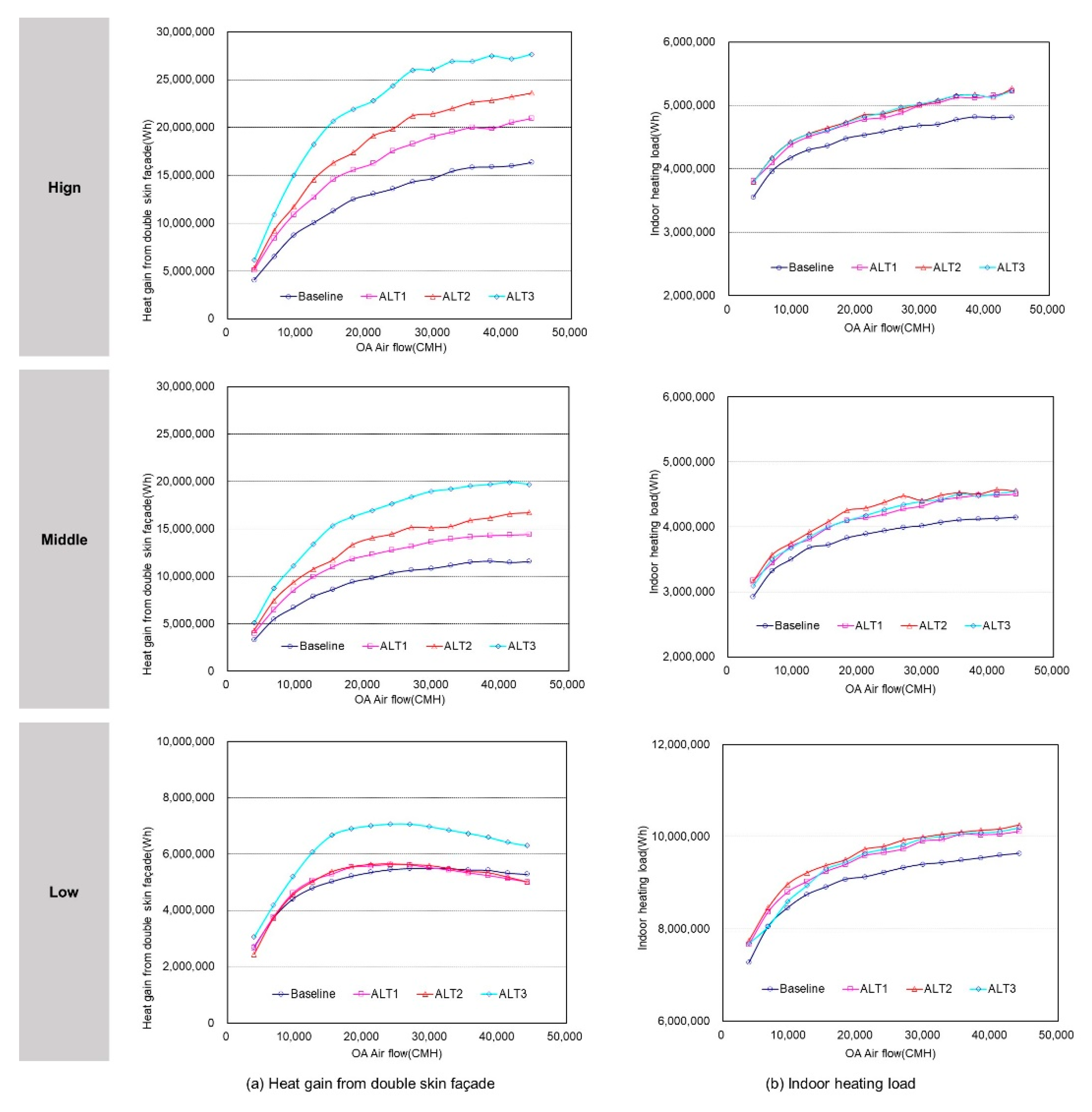
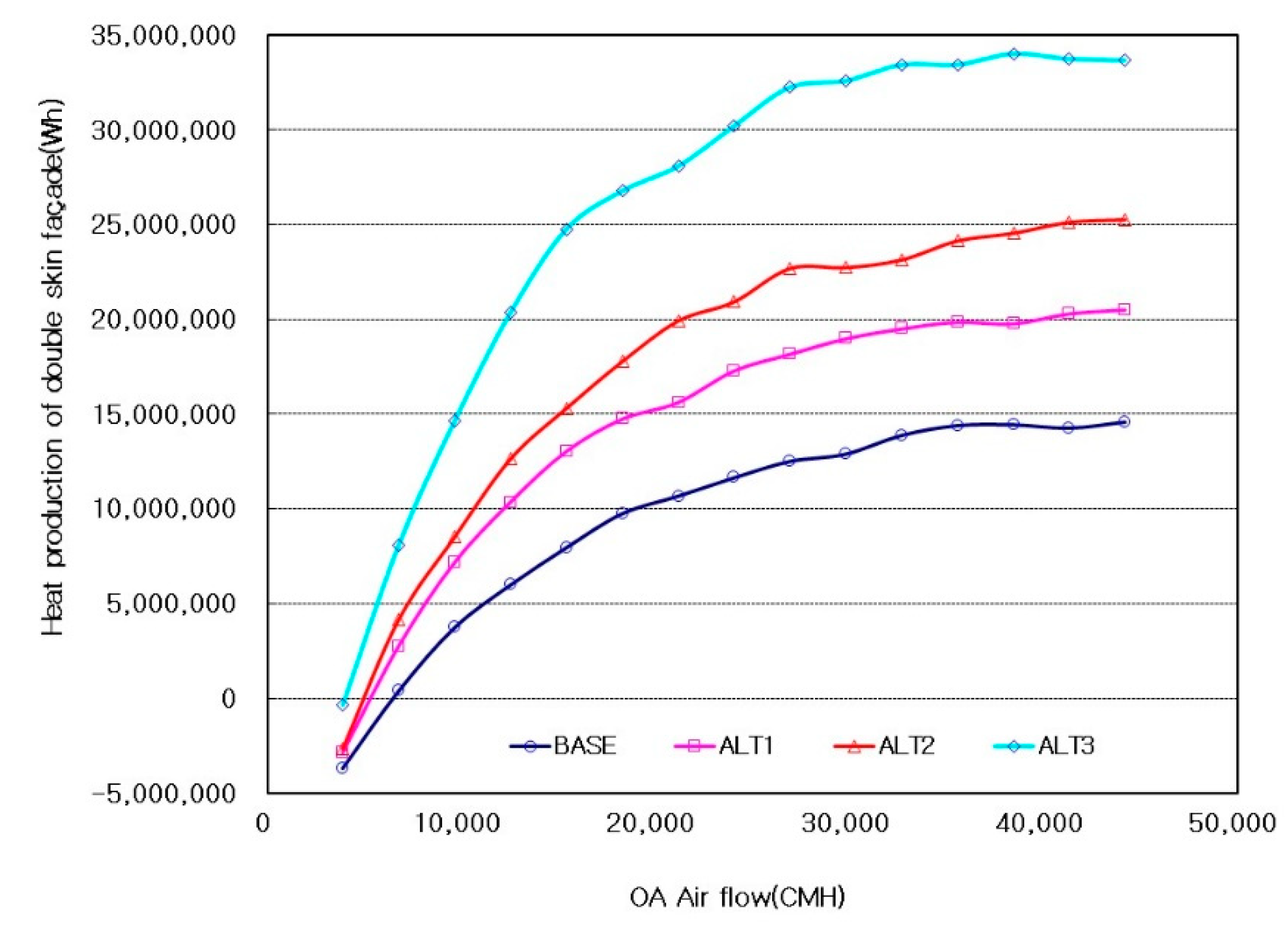
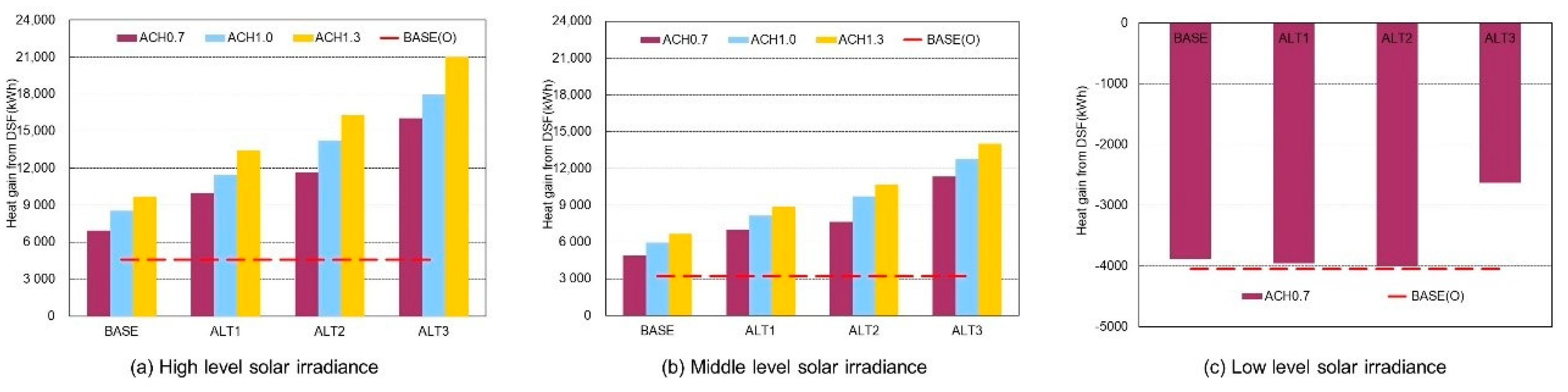
Figure 12 shows the double-skin facade-based heat and indoor heating load for the period (November to March) according to the OA-based air volume. In terms of double-skin facade-based heat, when solar irradiance was at the high and middle levels, each alternative plan showed that with a rise in OA-based air volume, the double-skin facade-based heat gradually increased and remained almost unchanged in the range of about 26,000 CMH and above. When solar irradiance was at the low level, each alternative plan showed that with a rise in OA-based air volume, the double-skin facade heat gradually increased, and remained almost unchanged and then decreased to a value in the range of about 15,000 CMH and above. In each alternative plan, with the application of an SC and a rise in its height, the double-skin facade-based heat also increased. The ALT3, which implemented thermal effect, showed the highest heat value. On balance, with an increase in the amount of irradiance of the double-skin facade, the OA-based air volume also went up. Additionally, with the application of an SC to the upper side of the double-skin facade, solar heat was used more, and therefore the OA utilization through the double-skin facade was larger.
In terms of annual heating load according to the double-skin facade-based air volume, with a rise in OA-based air volume, the temperature distribution by cavity height and the surface heat resistance of the inner wall were lowered and therefore indoor heating load gradually increased, but it was lower than of the the double-skin facade-based heat. Compared to the baseline model, each alternative plan showed that with the application of an SC and a rise in its height, the buoyancy of the air of the cavity caused heat concentration on the SC path and thereby the 1F to 5F cavity air temperature was relatively lowered and indoor load somewhat increased. Nevertheless, ALT1, ALT2, and ALT3 had a similar distribution of annual heating load without any great difference.
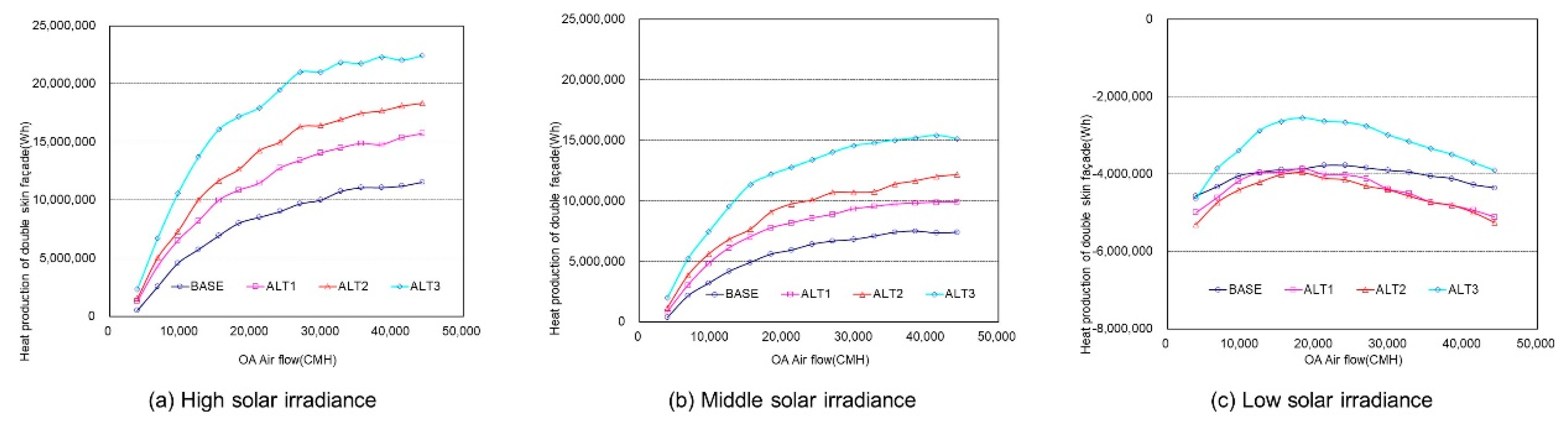
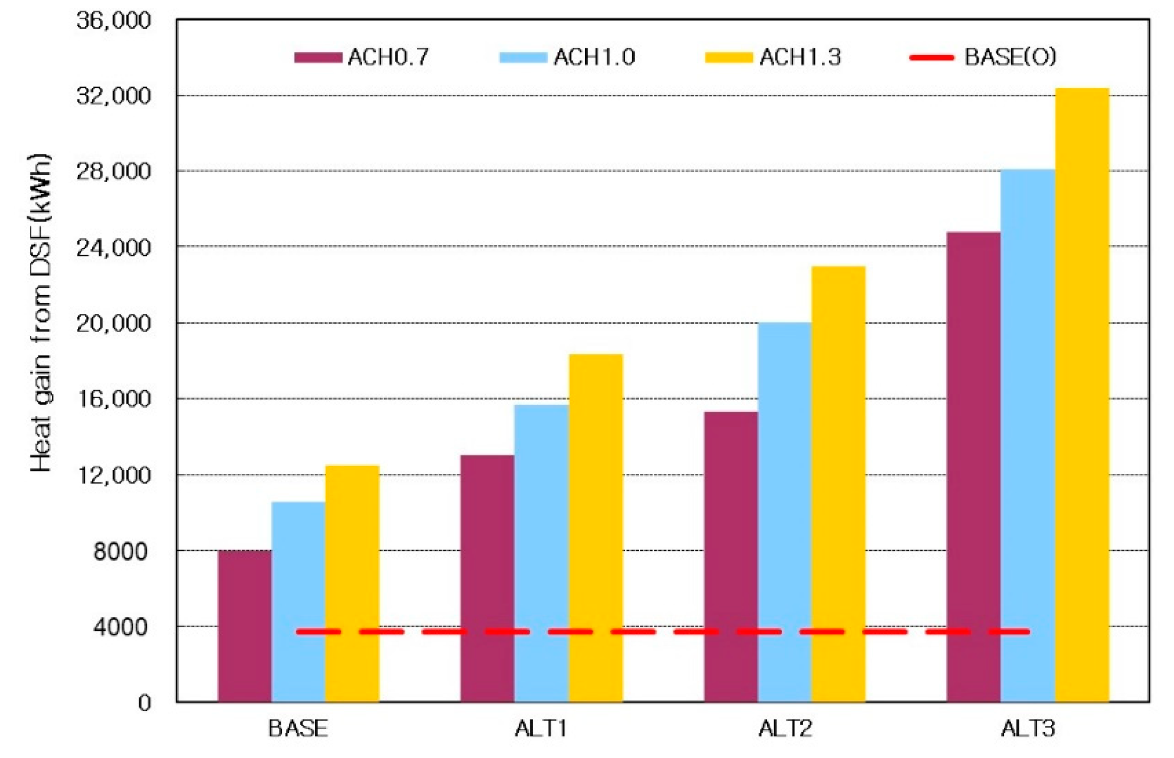
Figure 13 illustrates the analysis results of the double-skin facade-based heat production in each alternative plan according to OA-based heat and solar irradiance. The double-skin facade-based heat production proposed in this study is the total of the double-skin facade-based heat and indoor heat loss load by each OA-based air volume. It refers to the net heat production at the time when the double-skin facade is used as the preheating path of OA. When the daily accumulated irradiance of the multistory double-skin facade was 2000 Wh/m
2 and more, the double-skin facade-based heat was larger than the indoor heat loss load. When it was less than 2000 Wh/m
2, indoor heat loss load was relatively larger, and therefore, general loss occurred. In the analysis of each alternative plan, the heat produced by the double-skin facade increased in the order of Baseline < ALT1 < ALT2 < ALT3 as an SC was applied and its height went up. The ALT3, which implemented thermal effect on the SC path, produced the highest heat.
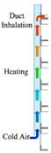
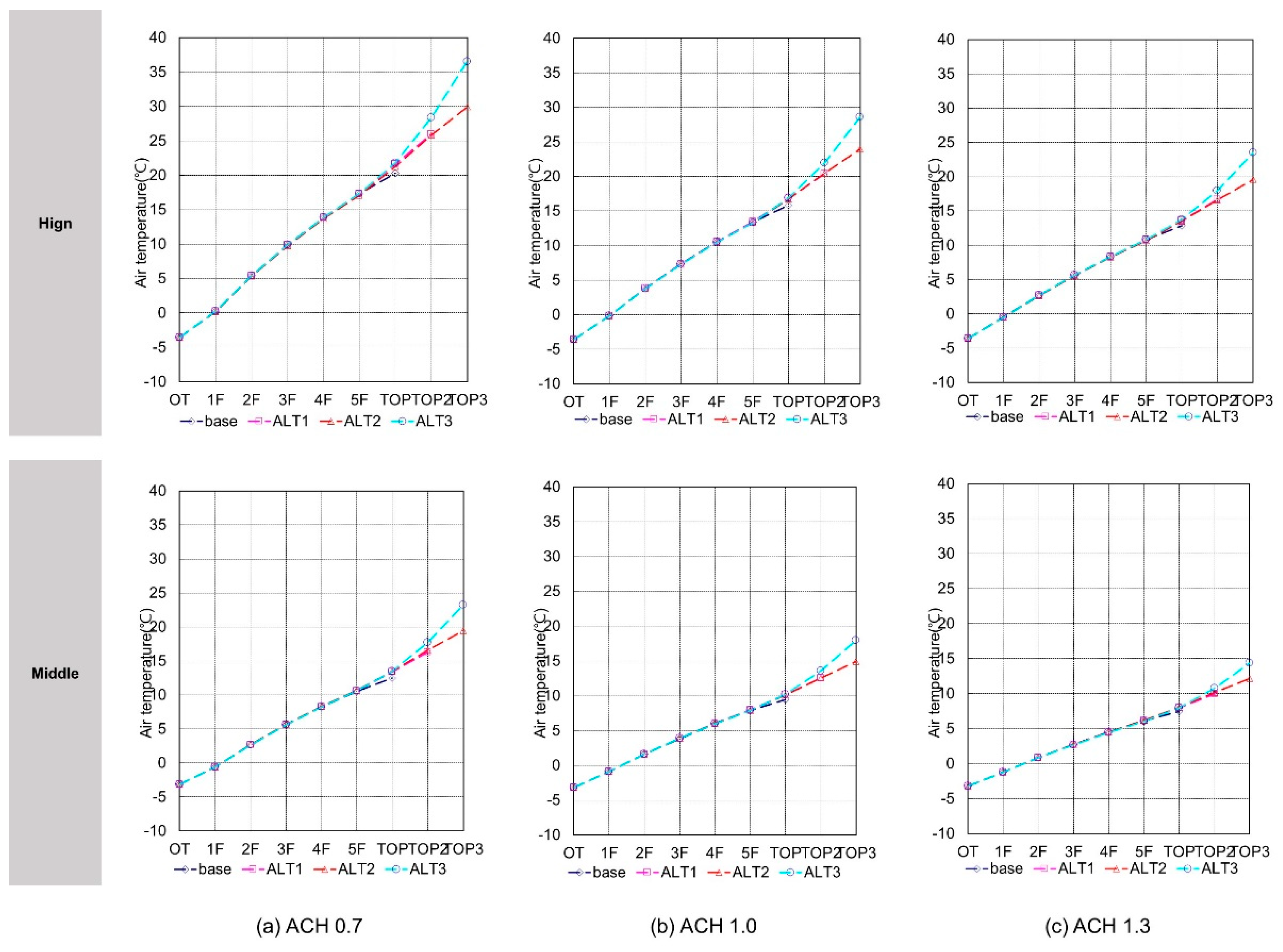
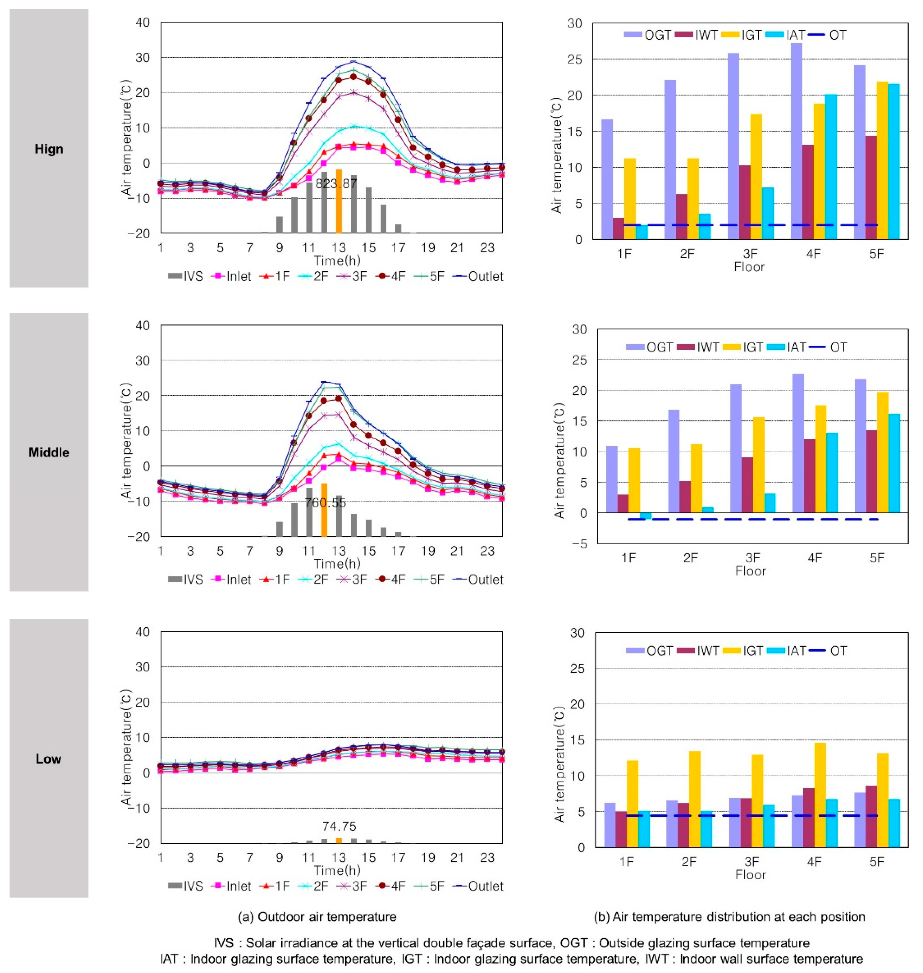
Figure 14 presents the air temperature of the cavity in each alternative plan on the analysis days of solar irradiance selected at the time of measurement. With a rise in solar irradiance, the temperature difference between the upper and lower sides in the double-skin facade was larger. With an increase in the installation height of the SC, there was no great difference in the air temperature of the cavity close to indoor (1F–5F) in each plan. However, the air temperature in the SC path gradually increased with a rise in the SC height. The highest temperature increase occurred in ALT3.
This study chose a range of constant increase of double-skin facade-based heat with a rise in OA-based air volume as an appropriate OA-based air volume range. Therefore, when solar irradiance was at the high and middle levels, 2600 CMH was chosen as the maximum OA-based air volume; when at the low level, 1500 CMH was chosen as the maximum OA-based air volume. When the solar irradiance of all the air conditioning zones of the building was at the high and middle levels, the number of maximum air changes was 1.3 times/h; when the solar irradiance was at the low level, it was 0.7 times/h. These numbers met the ventilation requirement of 0.7 times/h and above prescribed in ‘Rules of Building Facilities Standards, Etc. (2006)’ of the Ministry of Land, Transport and Maritime Affairs. Air changes for introducing fresh outdoor air can be different depending on the operation intention of building and on irradiance. Therefore, when solar irradiance was at the high and middle levels, three operation plans (number of air changes: 0.7, 1, and 1.3 times/h) were established, and then the temperature, pressure, and heat production of the double-skin facade cavity were analyzed according to the number of air changes.
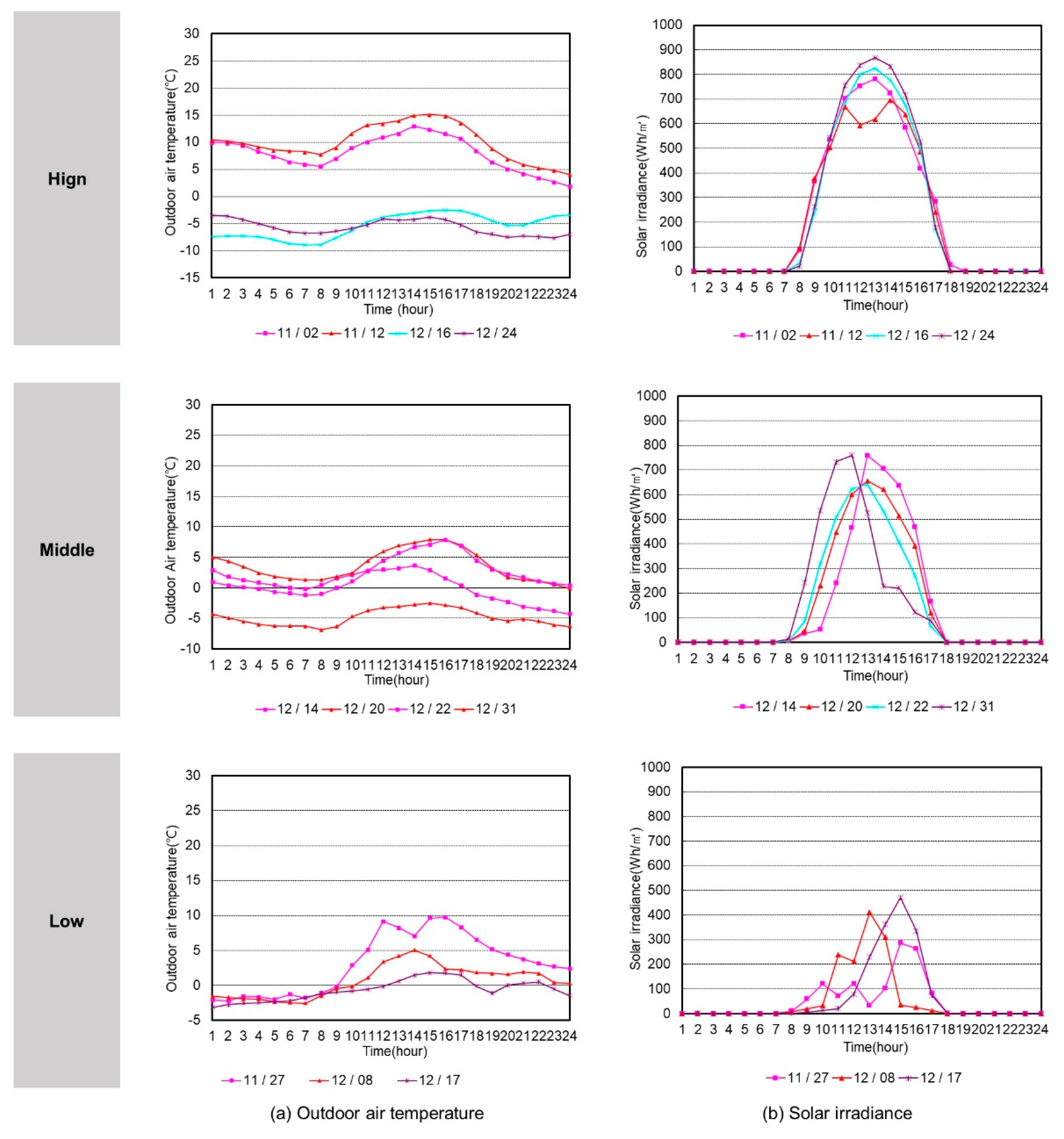
The cavity air temperature on the analysis days for solar irradiance in winter was analyzed according to the number of air changes.
Figure 15 shows the average cavity air temperatures in the daytime (11:00–16:00) on analysis days when solar irradiance was at the high and middle levels according to the number of air changes. The lower the solar irradiance was, the smaller the cavity air temperature difference and overall temperature distribution in the upper and lower sides of the double-skin facade were. The cavity air temperatures in each alternative plan were analyzed. As a result, in all alternative plans, a similar temperature rise inclination remained from 1F to TOP. With the application of an SC and a rise in its height, the temperature rise inclination found in the lower side of the SC (1F–TOP) remained constant, and the temperature in the SC zone gradually increased. However, in the ALT 3 that implemented thermal effect, the temperature rise inclination in the SC zone was relatively larger, and thereby the temperature was the highest. With an increase in the number of air changes, the temperature rise inclination in all zones of the double-skin facade became smaller and the temperature went down overall.
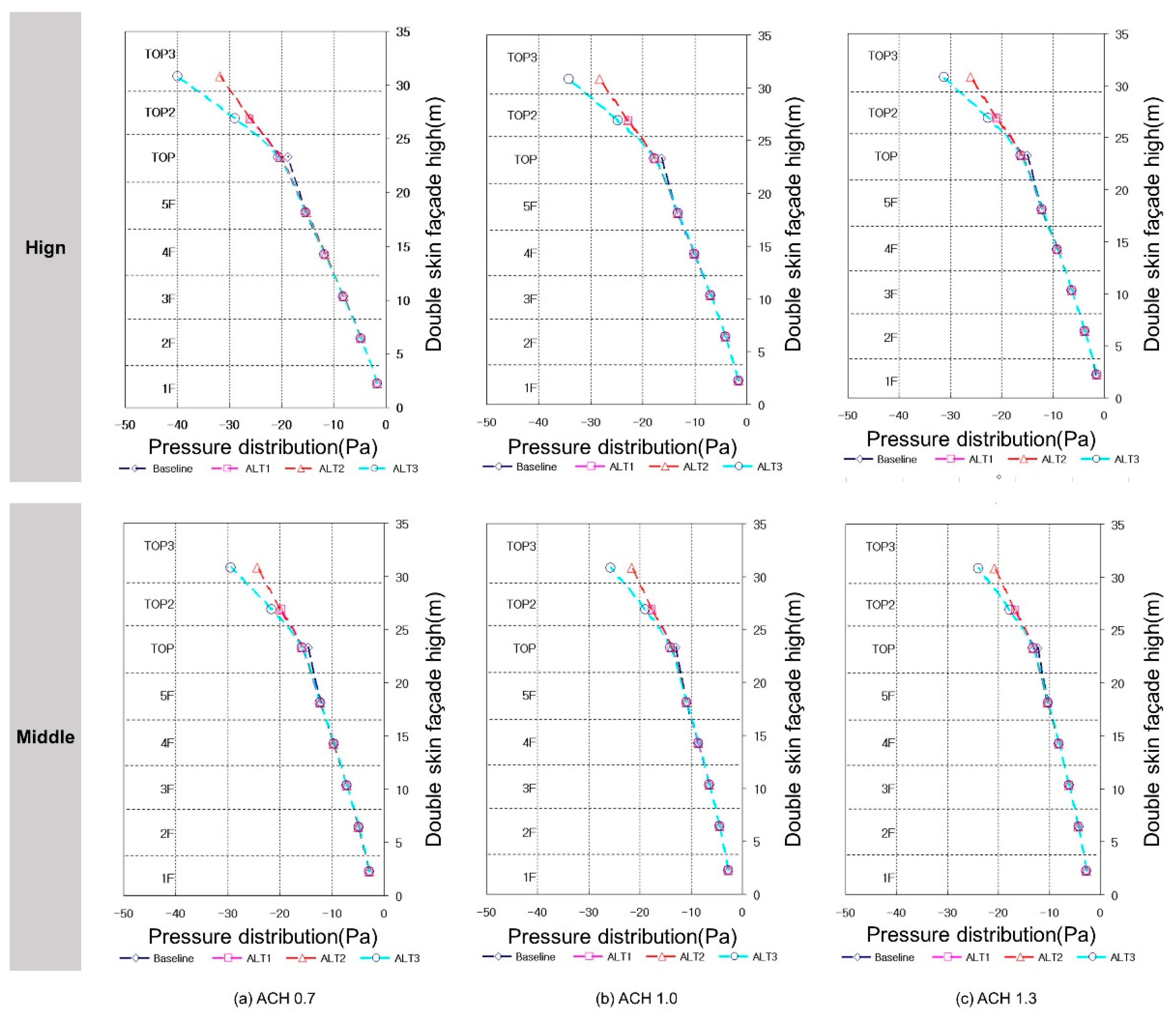
Figure 16 illustrates the average cavity pressure in the daytime (11:00–16:00) on the analysis days when solar irradiance was at the high level, according to the number of air changes. With a decrease in solar irradiance, the pressure difference and overall pressure in the upper and lower sides of the double-skin facade were smaller. Each alternative plan had the following cavity pressure:
In all the alternative plans, a similar pressure rise inclination remained from 1F to TOP. With the application of an SC and a rise in its height, the pressure rise inclination found in the lower side of the SC (1F–TOP) remained constant, and the pressure in the SC zone gradually increased. However, in the ALT 3 that implemented thermal effect, the pressure rise inclination in the SC zone was relatively larger, and thereby the pressure was the highest. With an increase in the number of air changes, the temperature difference and air density difference in the vertical direction of the double-skin facade became smaller and the pressure went down overall.
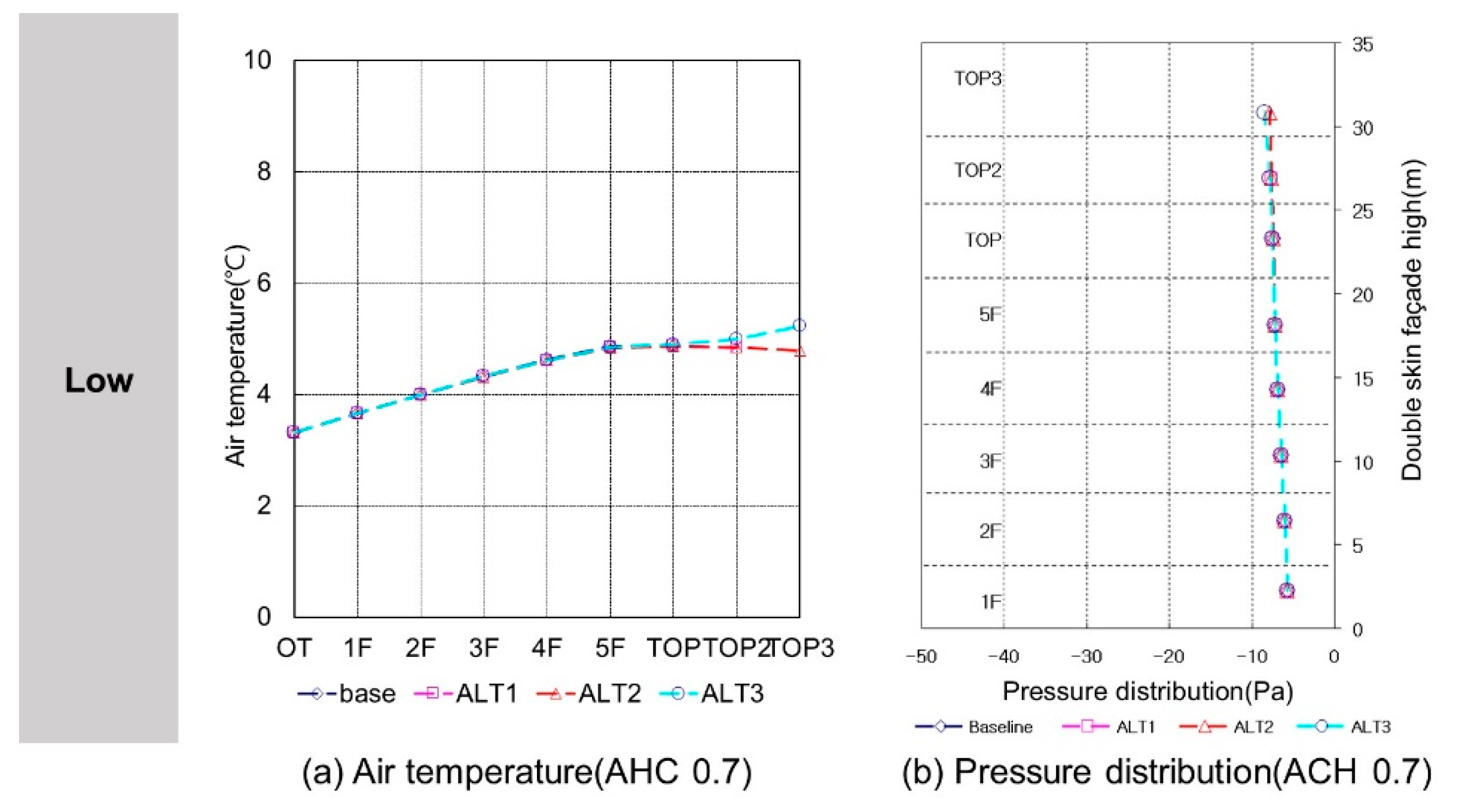
Figure 17 presents the average cavity air temperature and pressure in the daytime (11:00–16:00) when solar irradiance was at the low level. In terms of cavity air temperature, in all the alternative plans, a similar temperature rise inclination remained. However, with the application of an SC and a rise in its height, the temperature in the SC zone remained almost same as the temperature in the TOP with no temperature rise. In the ALT 3 that implemented thermal effect, the air temperature somewhat increased in the SC zone, but its temperature rise was smaller than that in the 1F–TOP zone. The overall temperature distribution was lower than that at the time when solar irradiance was at the high and middle levels. In terms of cavity air temperature, the application of an SC and a rise in its height and thermal effect were not influential. In all the alternative plans, a small and similar pressure rise inclination remained in each vertical zone. As the temperature difference and air density difference in the vertical direction of the double-skin facade became smaller, the pressure was lower than that at the time when solar irradiance was at the high and middle levels.
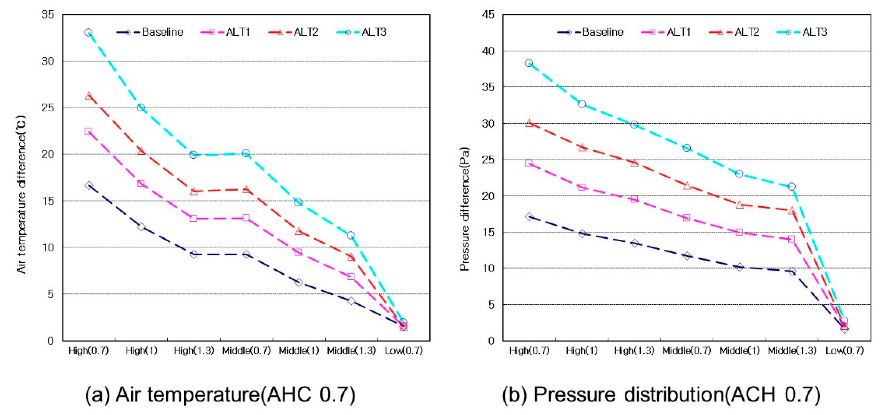
Figure 18 illustrates the temperature difference and pressure difference on the top and bottom in each alternative plan on the basis of the average cavity air temperature and pressure in the daytime (11:00–16:00) on analysis days when solar irradiance was at the high, middle, and low levels. A temperature difference is the reference to judge the available heat of the double-skin facade, presenting the difference between the top temperature and outdoor air temperature in each alternative plan. A pressure difference means the difference between the top pressure and the bottom (1F) pressure in each alternative plan. With a rise in the solar irradiance of the double-skin facade, the temperature and pressure differences between the top and bottom in each alternative plan increased. In particular, the ALT 3 that implemented thermal effect showed the largest temperature and pressure differences by available air volumes, showing the highest possibility of heat production. When solar irradiance was at the low level, all alternative plans showed similar temperature and pressure differences, so that energy production with the use of solar heat was not different in each alternative plan.
The annual indoor heating load according to the application of an SC and OA-based air volume was analyzed.
Table 6 shows the heating air conditioning time in each alternative plan. BASE(O) is the heating air conditioning time when the original OA-based air volume was applied to the double-skin facade used in this study. The lower the solar irradiance was, the higher the OA-based air volume was and the greater the heating air conditioning time was. So, the baseline model had the smallest heating air conditioning time overall. Based on the ALT1 with the greatest heating air conditioning time, the average outdoor air temperature of heating air conditioning time in each one of the high, middle, and low levels of solar irradiance was calculated. As a result, the outdoor air temperature was highest in the order of low level (3.44 °C) > middle level (0.65 °C) > high level (−3.54 °C) of solar irradiance.
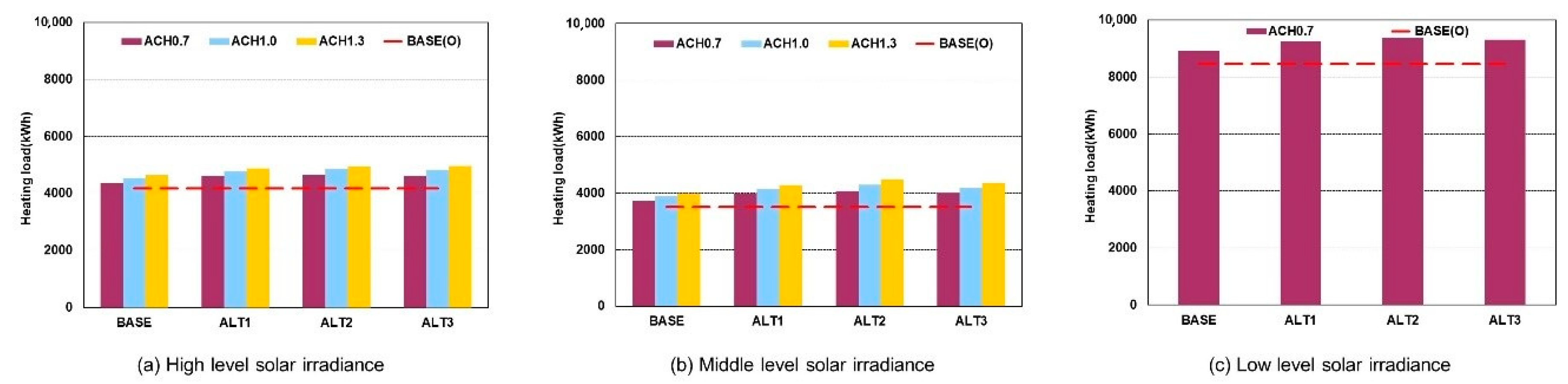
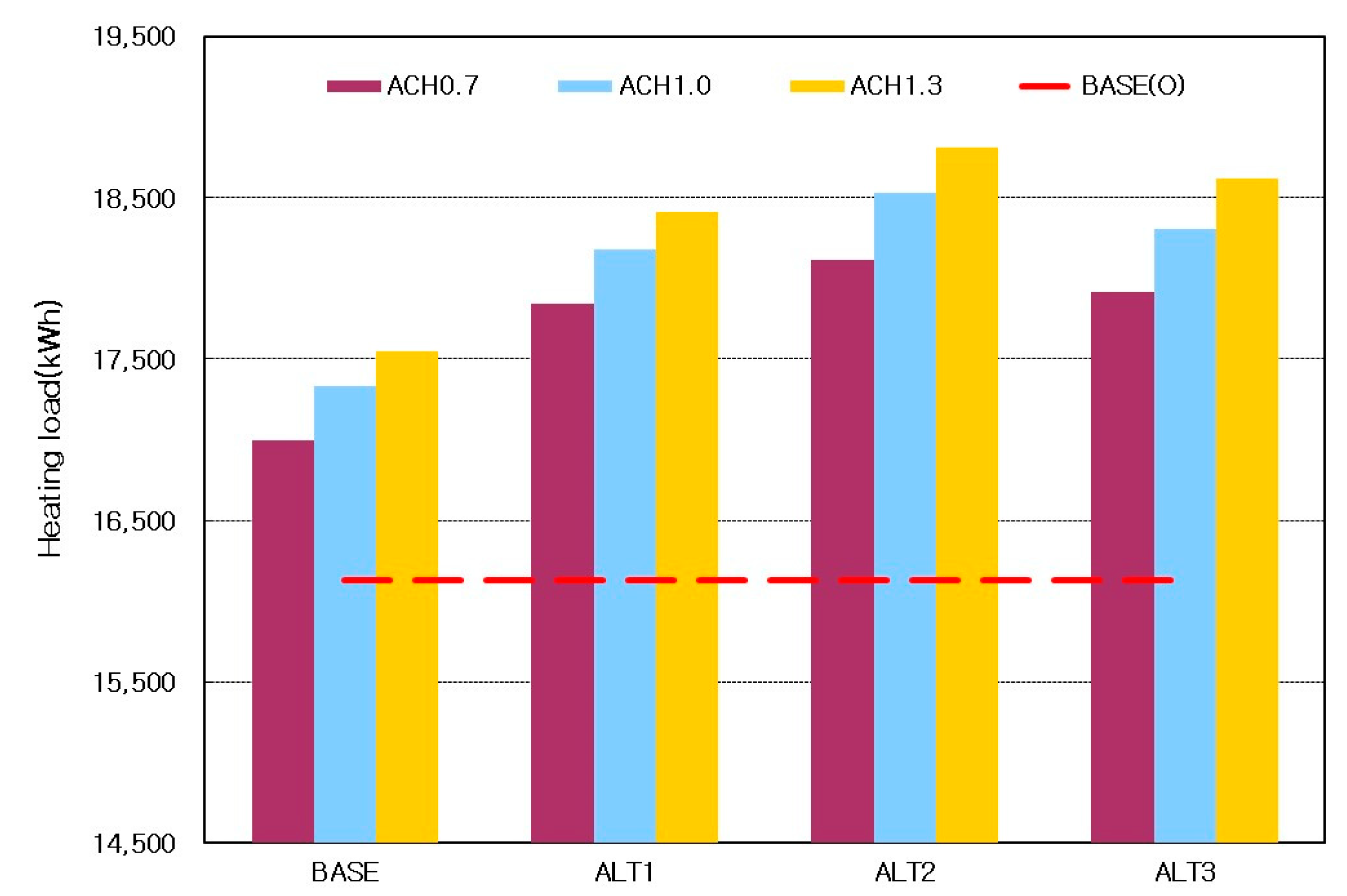
Figure 19 shows the annual indoor heating load in each alternative plan according to solar irradiance. Compared to the BASE (O) model, all alternative plans had relatively higher heating loads.
Figure 20 presents the total heating load (including indoor heating load) according to solar irradiance. As shown in the figure, with the application of an SC and a rise in its height, and also an increase in OA-based air volume, the load was high overall. However, the ALT3 that applied thermal effect to the SC had a somewhat lower load than ALT2. Therefore, ALT2 had the highest annual indoor heating load.
Figure 21 illustrates the annual double-skin facade-based heat in each alternative plan according to solar irradiance. All alternative plans had higher heat than the BASE(O) model.
Figure 22 presents the total available heat (including the heat using the solar heat of the double-skin facade) according to solar irradiance. As shown in the figure, with the application of an SC and a rise in its height, and an increase in OA-based air volume, the heat was high overall. The ALT3 that applied thermal effect to the SC had the highest annual double-skin facade-based heat.
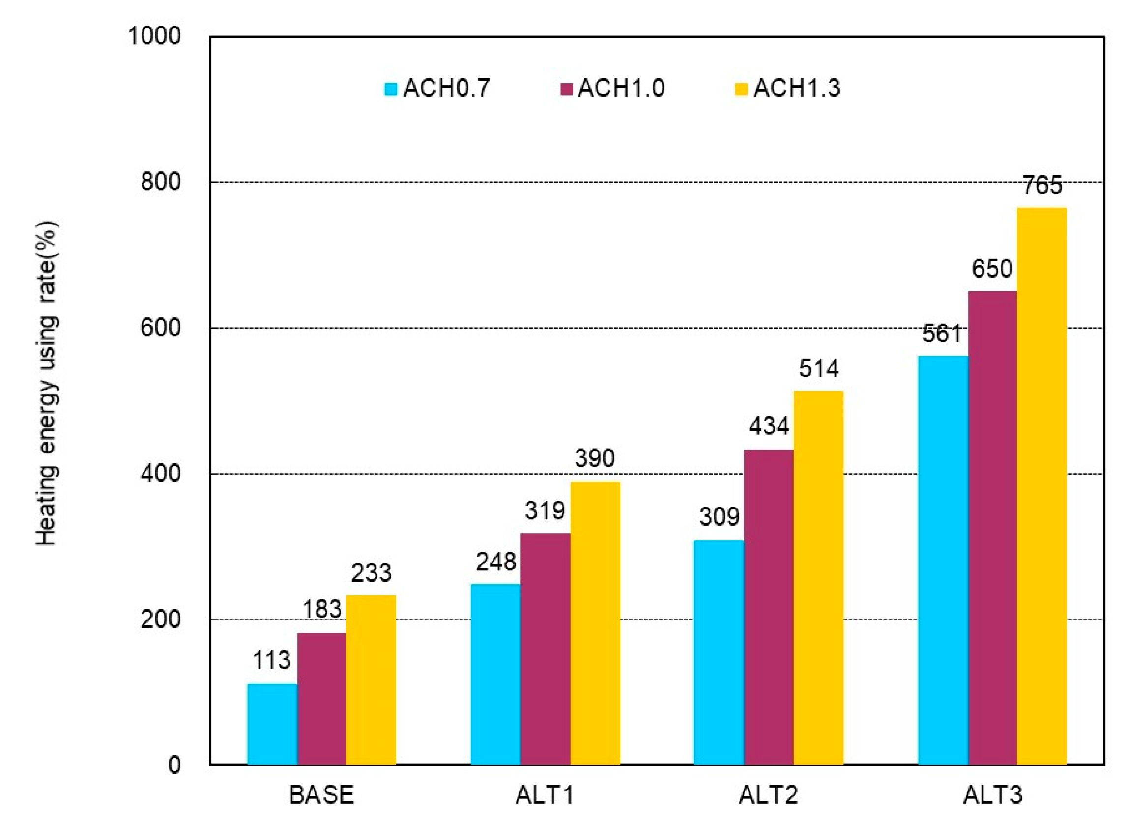
Figure 23 shows the heating energy use rate of each alternative plan for the BASE (O) model in terms of the original OA-based air volume of the double-skin facade. With the application of an SC and a rise in its height, the available capacity of the solar irradiance of the double-skin facade increased, and thereby the use rate of heating energy increased. With a rise in the OA-based air volume in each alternative plan, the use rate also increased. The ALT3 that applied thermal effect to the SC had the highest heating energy use rate. When ACH was 1.3, it was possible to use heating energy about 7.6 times higher than the BASE(O) model.
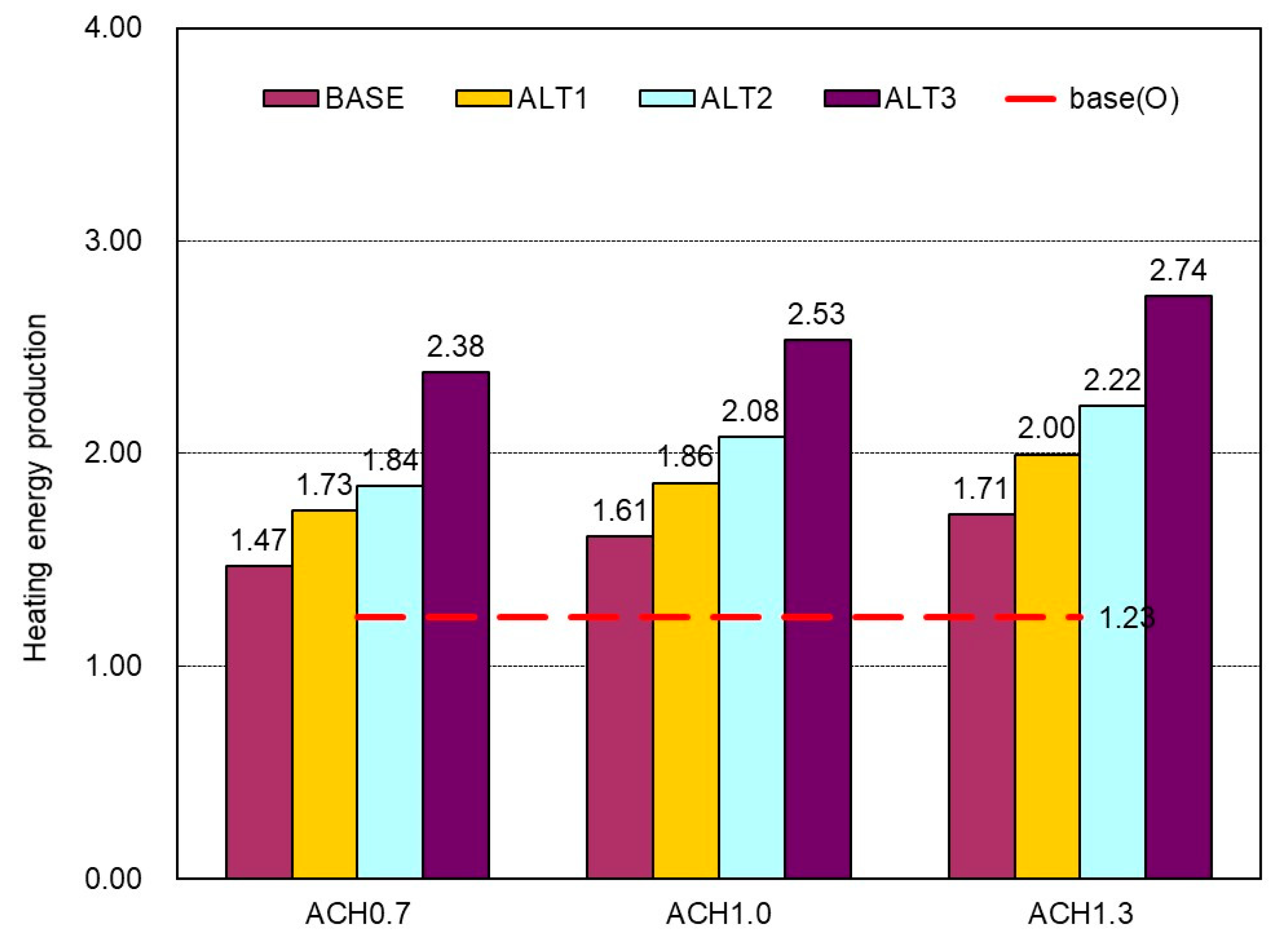
Figure 24 presents the annual heating energy production capacity of the double-skin facade in each alternative plan according to OA-based air volume. The heating energy production capacity of the double-skin facade presents the heating loss load ratio in the installation side of the double-skin facade for the net solar heat-based energy of the double-skin facade of the building, which uses the cavity as the preheating path of air conditioning OA.
The heating energy production capacity of the double-skin facade varies depending on the indoor plain type, volume, and insulation performance of the outer skin in the installation side of the double-skin facade. Nevertheless, when the capacity exceeds ‘1’ at least, it is judged that the heating energy generated by the double-skin facade has productivity. According to the analysis, the BASE(O) model with the original OA-based air volume of the double-skin facade used in this study had a heating energy production capacity of 1.23. With the application of an SC and a rise in its height, the heating energy production capacity increased. With an increase in OA-based air volume in each alternative plan, the heat production capacity also went up. In the ALT3 that applied thermal effect to the SC, when the ACH was 1.3, the heating energy production capacity was the highest, at 2.74.
In the winter evaluation, the indoor load according to the OA-based air volume and the OA based-heat through the double-skin facade was analyzed in each SC-based alternative plan proposed to improve the heat performance of the double-skin facade. The higher the OA-based air volume was, the higher the double-skin facade-based heat was. The range that began to make the increase in double-skin facade-based heat remain constant was chosen as the appropriate OA-based air volume range (the high and middle levels of solar irradiance: 26,000 CMH or less, the low level of solar irradiance: 15,000 CMH or less). In the chosen OA-based air volume range, as solar irradiance increased, the temperature difference and pressure of the cavity in the upper and lower sides of the double-skin facade increased, and thereby the available heat through the double-skin facade went up. In addition, with the application of an SC and a rise in its height, the available capacity of the solar irradiance of the double-skin facade rose and the heating energy use rate increased. Among the alternative plans, the ALT3 that applied thermal effect had the highest heating energy use rate. In ALT3, when the ACH was 1.3, it was possible to use heating energy about 7.6 times higher than the original performance of the double-skin facade operated with ACH 0.4. Therefore, the heating energy production capacity in ALT3 was the highest, at 2.74. According to the winter evaluation, with the application of an SC and a rise in its height, the heating energy saving was excellent. When thermal effect was applied to the SC, the heating energy utilization effect of solar irradiance of the double-skin facade was large.


