Performance Analyses of a Renewable Energy Powered System for Trigeneration


Abstract
:1. Introduction
2. System Description and Modelling
- Atmospheric temperature and pressure (dead state properties) are assumed to be 101 kPa and 298 K, respectively.
- The turbine and pumps are considered adiabatic.
- The system operates on steady state conditions.
- The idea gas properties are chosen for air to perform the analysis.
- Potential and kinetic energy changes are negligible.
- Total combustion in gas cycle is assumed with an 80% combustion efficiency.
3. Results and Discussions
4. Conclusions
- Biogas production is from 70,000 kg and 30,000 kg of chicken manure and maize silage respectively.
- Trigeneration system produces 1460 kW of electrical energy, 280.8 kW of cooling and 122.6 L/mins of hot water.
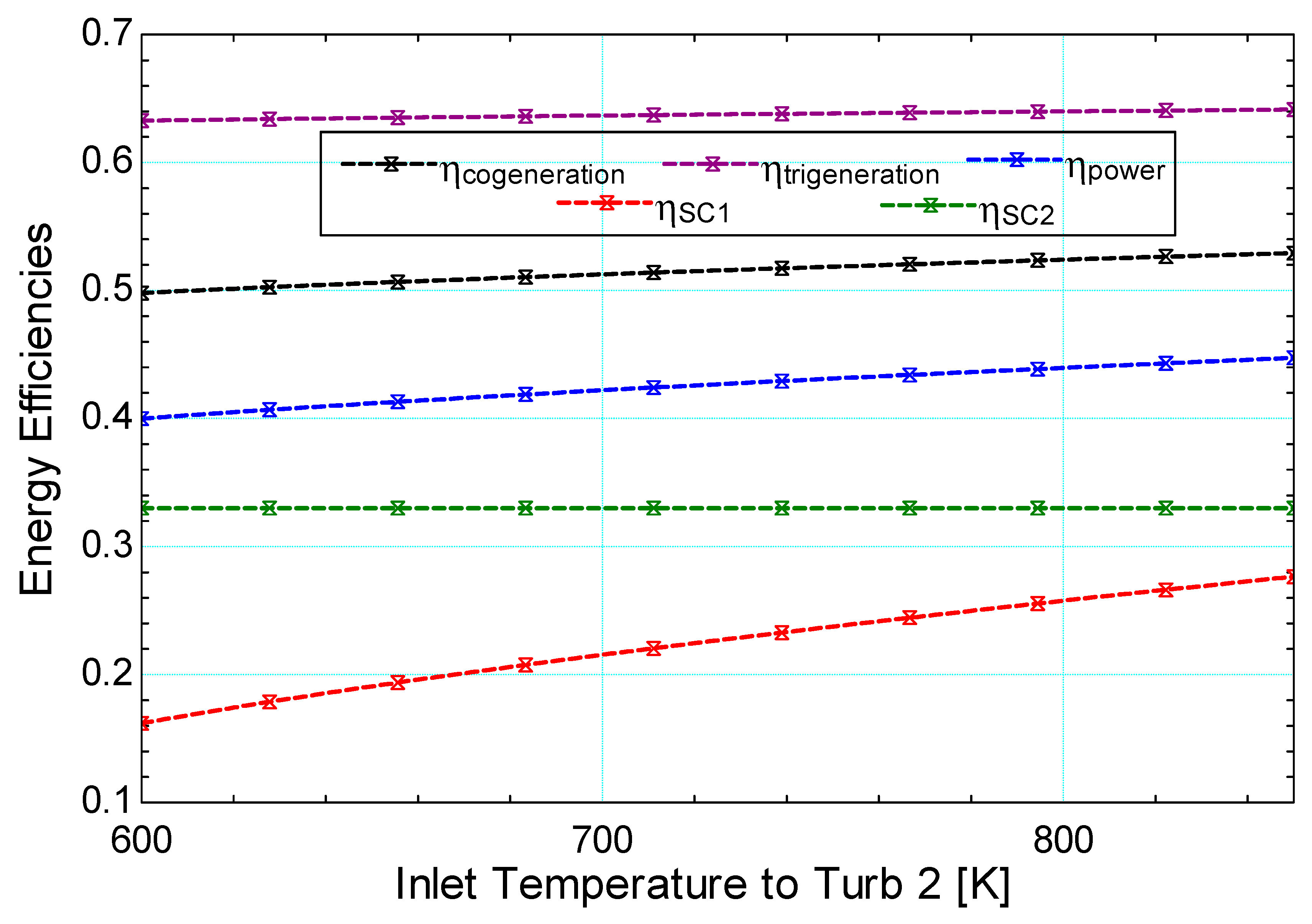
- The systems energy and exergy performance increase as more useful outputs are produced. The energy and exergy efficiency of the system respectively increases from 43.96% and 33.34% when generating electrical energy only to 64% and 34.51% when used for trigeneration.
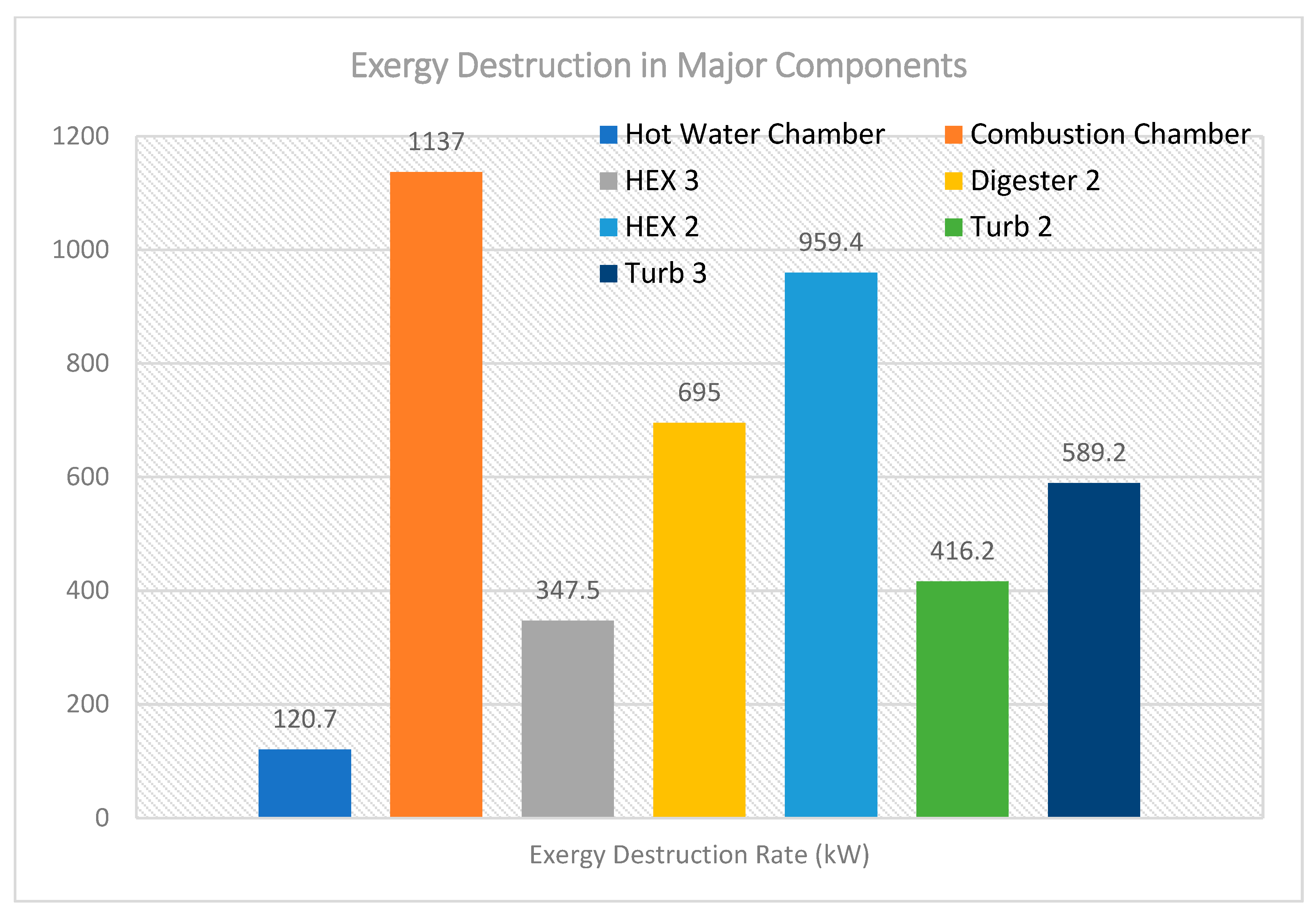
- Exergy destruction is greatest in the combustion chamber in the multi-generation system.
- This trigeneration system will be suitable for developed and developing countries, where the biogas raw materials are readily available.
Author Contributions
Funding
Conflicts of Interest
Abbreviations
| abs | Absorption |
| CFWH | Closed Feedwater Heater |
| COP | Coefficient of Performance |
| E | Evaporator |
| HEX | Heat Exchanger |
| HW | Hot Water |
| OFWH | Open Feedwater Heater |
| P | Pump |
| S. EX | Solution Heat Exchanger |
| ST | Steam Trap |
| Turb | Turbine |
| V | Valve |
Nomenclatures
| Exergy | |
| h | Enthalpy |
| m | Mass flowrate |
| P | Pressure |
| Q | Useful Energy |
| S | Entropy |
| T | Temperature |
| u | Velocity |
| W | Work |
Greek Letters
| Efficiency | |
| Ψ | Exergy |
References
- International Renewable Energy Agency (IRENA). Electricity Storage and Renewables: Costs and Markets to 2030; IRENA: Abu-Dhabi, United Arab Emirates, 2017; ISBN 978-92-9260-038-9. [Google Scholar]
- National Renewable Energy Laboratory. Renewable Electricity Futures Study (Entire Report); 4 vols. NREL/TP-6A20-52409; Hand, M.M., Baldwin, S., DeMeo, E., Reilly, J.M., Mai, T., Arent, D., Porro, G., Meshek, M., Sandor, D., Eds.; National Renewable Energy Laboratory: Golden, CO, USA, 2012. Available online: http://www.nrel.gov/analysis/re_futures/ (accessed on 25 June 2019).
- International Renewable Energy Agency (IRENA). Renewable Power Generation Costs in 2018; International Renewable Energy Agency: Abu Dhabi, United Arab Emirates, 2019; ISBN 978-92-9260-126-3. [Google Scholar]
- Varun, R.P.; Bhat, I.K. Energy, economics and environmental impacts of renewable energy systems. Renew. Sustain. Energy Rev. 2009, 13, 2716–2721. [Google Scholar] [CrossRef]
- Feng, Z.; Mao, Y.; Xu, N.; Zhang, B.; Wei, P.; Yang, D.-L.; Wang, Z.; Zhang, Z.; Zheng, R.; Yang, L.; et al. Multigeneration analysis reveals the inheritance, specificity, and patterns of CRISPR/Cas-induced gene modifications in Arabidopsis. Proc. Natl. Acad. Sci. USA 2014, 111, 4632–4637. [Google Scholar] [CrossRef]
- Dincer, I.; Zamfirescu, C. Renewable-energy-based multigeneration systems. Int. J. Energy Res. 2012, 36, 1403–1415. [Google Scholar] [CrossRef]
- Dincer, I.; Rosen, M.A. Exergy Analysis of Integrated Trigeneration and Multigeneration Systems. In Exergy, 2nd ed.; chapter 14; Elsevier Ltd.: Amsterdam, The Netherlands, 2012. [Google Scholar] [CrossRef]
- Ozlu, S.; Dincer, I. Development and analysis of a solar and wind energy based multigeneration system. Sol. Energy 2015, 122, 1279–1295. [Google Scholar] [CrossRef]
- Al-Ali, M.; Dincer, I. Energetic and exergetic studies of a multigenerational solar–geothermal system. Appl. Therm. Eng. 2014, 71, 16–23. [Google Scholar] [CrossRef]
- Khalid, F.; Dincer, I.; Rosen, M.A. Thermoeconomic analysis of a solar-biomass integrated multigeneration system for a community. Appl. Therm. Eng. 2017, 120, 645–653. [Google Scholar] [CrossRef]
- Islam, S.; Dincer, I.; Yilbas, B.S. Development, analysis and assessment of solar energy-based multigeneration system with thermoelectric generator. Energy Convers. Manag. 2018, 156, 746–756. [Google Scholar] [CrossRef]
- Hashemian, N.; Noorpoor, A. Assessment and multi-criteria optimization of a solar and biomass-based multi-generation system: Thermodynamic, exergoeconomic and exergoenvironmental aspects. Energy Convers. Manag. 2019, 195, 788–797. [Google Scholar] [CrossRef]
- Yilmaz, F.; Ozturk, M.; Selbas, R. Design and thermodynamic analysis of coal-gasification assisted multigeneration system with hydrogen production and liquefaction. Energy Convers. Manag. 2019, 186, 229–240. [Google Scholar] [CrossRef]
- Ishaq, H.; Dincer, I.; Naterer, G.F. Multigeneration system exergy analysis and thermal management of an industrial glassmaking process linked with a Cu–Cl cycle for hydrogen production. Int. J. Hydrogen Energy 2019, 44, 9791–9801. [Google Scholar] [CrossRef]
- Shengjun, Z.; Huaixin, W.; Tao, G. Performance comparison and parametric optimization of subcritical Organic Rankine Cycle (ORC) and transcritical power cycle system for low-temperature geothermal power generation. Appl. Energy 2011, 88, 2740–2754. [Google Scholar] [CrossRef]
- Yari, M. Exergetic analysis of various types of geothermal power plants. Renew. Energy 2010, 35, 112–121. [Google Scholar] [CrossRef]
- Hepbasli, A.; Akdemir, O. Energy and exergy analysis of a ground source (geothermal) heat pump system. Energy Convers. Manag. 2004, 45, 737–753. [Google Scholar] [CrossRef]
- Ebadollahi, M.; Rostamzadeh, H.; Pedram, M.Z.; Ghaebi, H.; Amidpour, M. Proposal and assessment of a new geothermal-based multigeneration system for cooling, heating, power, and hydrogen production, using LNG cold energy recovery. Renew. Energy 2019, 135, 66–87. [Google Scholar] [CrossRef]
- Acar, C.; Dincer, I. Investigation of a unique integrated photoelectrochemical system for multigeneration purposes. Int. J. Hydrogen Energy 2019, 44, 18756–18766. [Google Scholar] [CrossRef]
- Yilmaz, F. Thermodynamic performance evaluation of a novel solar energy based multigeneration system. Appl. Therm. Eng. 2018, 143, 429–437. [Google Scholar] [CrossRef]
- Baghernejad, A.; Yaghoubi, M.; Jafarpur, K. Exergoeconomic optimization and environmental analysis of a novel solar-trigeneration system for heating, cooling and power production purpose. Sol. Energy 2016, 134, 165–179. [Google Scholar] [CrossRef]
- Taheri, M.; Mosaffa, A.; Farshi, L.G. Energy, exergy and economic assessments of a novel integrated biomass based multigeneration energy system with hydrogen production and LNG regasification cycle. Energy 2017, 125, 162–177. [Google Scholar] [CrossRef]
- Ahmadi, P.; Dincer, I.; Rosen, M.A. Thermoeconomic multi-objective optimization of a novel biomass-based integrated energy system. Energy 2014, 68, 958–970. [Google Scholar] [CrossRef]
- Ptasinski, K.J.; Prins, M.J.; Pierik, A. Exergetic evaluation of biomass gasification. In Proceedings of the 18th International Conference on Efficiency, Cost, Optimization, Simulation, and Environmental Impact of Energy Systems, Trondheim, Norway, 20–22 June 2005. [Google Scholar]
- El-Emam, R.S.; Dincer, I.; Naterer, G.F. Energy and exergy analyses of an integrated SOFC and coal gasification system. Int. J. Hydrogen Energy 2012, 37, 1689–1697. [Google Scholar] [CrossRef]
- Khalid, F.; Dincer, I.; Rosen, M.A. Energy and exergy analyses of a solar-biomass integrated cycle for multigeneration. Sol. Energy 2015, 112, 290–299. [Google Scholar] [CrossRef]
- Wang, J.; Yang, Y. Energy, exergy and environmental analysis of a hybrid combined cooling heating and power system utilizing biomass and solar energy. Energy Convers. Manag. 2016, 124, 566–577. [Google Scholar] [CrossRef]
- Kanoglu, M.; Bolatturk, A. Performance and parametric investigation of a binary geothermal power plant by exergy. Renew. Energy 2008, 33, 2366–2374. [Google Scholar] [CrossRef]
- Rostamzadeh, H.; Gargari, S.G.; Namin, A.S.; Ghaebi, H. A novel multigeneration system driven by a hybrid biogas-geothermal heat source, Part II: Multi-criteria optimization. Energy Convers. Manag. 2019, 180, 859–888. [Google Scholar] [CrossRef]
- Huang, Y.; Wang, Y.; Rezvani, S.; McIlveen-Wright, D.; Anderson, M.; Mondol, J.; Zacharopolous, A.; Hewitt, N. A techno-economic assessment of biomass fuelled trigeneration system integrated with organic Rankine cycle. Appl. Therm. Eng. 2013, 53, 325–331. [Google Scholar] [CrossRef]
- Lian, Z.; Chua, K.J.; Chou, S. A thermoeconomic analysis of biomass energy for trigeneration. Appl. Energy 2010, 87, 84–95. [Google Scholar] [CrossRef]
- Al-Sulaiman, F.A.; Dincer, I.; Hamdullahpur, F. Thermoeconomic optimization of three trigeneration systems using organic Rankine cycles: Part II—Applications. Energy Convers. Manag. 2013, 69, 209–216. [Google Scholar] [CrossRef]
- Andiappan, V.; Ng, D.K.S.; Bandyopadhyay, S. Synthesis of Biomass-based Trigeneration Systems with Uncertainties. Ind. Eng. Chem. Res. 2014, 53, 18016–18028. [Google Scholar] [CrossRef]
- Li, H.; Zhang, X.; Liu, L.; Zeng, R.; Zhang, G. Exergy and environmental assessments of a novel trigeneration system taking biomass and solar energy as co-feeds. Appl. Therm. Eng. 2016, 104, 697–706. [Google Scholar] [CrossRef]
- Arnavat, M.P.; Bruno, J.C.; Coronas, A. Modeling of trigeneration configurations based on biomass gasification and comparison of performance. Appl. Energy 2014, 114, 845–856. [Google Scholar] [CrossRef]
- Pfeifer, J.; Obernberger, I. Technological evaluation of an agricultural biogas chp plant as well as definition of guiding values for the improved design and operation. In Proceedings of the 15th European Biomass Conference & Exhibition, Berlin, Germany, 7–11 May 2007. [Google Scholar]
- Sevinchan, E.; Dincer, I.; Lang, H. Energy and exergy analyses of a biogas driven multigenerational system. Energy 2019, 166, 715–723. [Google Scholar] [CrossRef]
- Ezzat, M.; Dincer, I. Energy and exergy analyses of a new geothermal–solar energy based system. Sol. Energy 2016, 134, 95–106. [Google Scholar] [CrossRef]
- Cengel, Y.A.; Boles, M.A. Thermodynamics an Engineering Approach, 9th ed.; Chapter 9 & 10; McGraw-Hill Education: New York, NY, USA, 2019; ISBN 125-98-2267-2. [Google Scholar]
- Dincer, I.; Rosen, M.A. Exergy: Energy, Environment and Sustainable Development; Elsevier Science: Amsterdam, The Netherlands, 2013; ISBN 978-00-8097-090-5. [Google Scholar]


| Definition | Poultry Litter | Maize Silage | Digestate |
|---|---|---|---|
| C [wt% kg d.b.] | 37.50 | 33.71 | 35.34 |
| O [wt% kg d.b.] | 29.40 | 16.86 | 24.36 |
| A [wt% kg d.b.] | 21 | 33.80 | 30.38 |
| H [wt% kg d.b.] | 5.5 | 4.47 | 4.53 |
| N [wt% kg d.b.] | 4.7 | 11.16 | 5.35 |
| Gas Cycle | |
| Mass flow rate (kg/s) | 3.256 |
| Turbine efficiency | 87% |
| Compression Ratio | 3 |
| Rated Pressure | 304 kPa |
| Combustion chamber efficiency | 80% |
| Rated Temperature | 1100 K |
| Steam Cycles | |
| Turbine efficiency | 85% |
| Pump Efficiency | 95% |
| Heat Exchanger Efficiency | 90% |
| Rated Temperature for Turb 1 and Turb 2 | 800 K |
| Rated Temperature for Turb 3 | 573 K |
| Rated Pressure for Turb 1 | 5000 kPa |
| Rated Pressure for Turb 2 | 1200 kPa |
| Rated Pressure for Turb 3 | 8000 kPa |
| Absorption Cycle | |
| Minimum Temperature | 279.1 K |
| Atmospheric Pressure (P0) | 101 kPa |
| Rated Pressure | 4.82 kPa |
| Refrigerant | LiBrH2O |
| Definition | Mathematical Model |
|---|---|
| Total work output | |
| Total power produced | |
| Pump/compressor Work input | |
| Turbine work output | |
| Evaporator work output | |
| Work equivalence of the hot water produced | |
| Power Energy Efficiency | |
| Biogas Energy Input | |
| The biogas LHV is the Lower Heating Value of the digestate and is 17.52 MJ [37]. | |
| Cogeneration energy efficiency | |
| Exergy at each point | |
| Biomass process total exergy rate | |
| Physical exergy per mass flow rate [40] | |
| Chemical exergy rate per mass flow [40] | |
| Where h, S, V, g, z, M, R and x are enthalpy, entropy, velocity, gravity, elevation, molecular weight, universal gas constant and molar concentration respectively at different state point. is the molecular weight. | |
| Exergy destruction | |
| Exergy destruction | |
| Reversible work output | |
| Reversible work input | |
| Power exergy efficiency | |
| Cogeneration exergy efficiency | |
| State No | Fluid Type | P (kPa) | M (kg/s) | T (K) | h (kJ/kg) |
|---|---|---|---|---|---|
| 0 | 101 | 298 | 104.2 | ||
| 4 | Biogas | 101.3 | 0.1896 | 304.5 | 10.85 |
| 5 | Biogas | 303.9 | 0.1896 | 313 | 21.11 |
| 6 | Air | 304 | 3.066 | 337.4 | 338 |
| 7 | Air | 101 | 3.066 | 298 | 298 |
| 8 | Air/Biogas | 304 | 3.256 | 1100 | 1168 |
| 9 | Air/Biogas | 101.3 | 3.256 | 886.1 | 895.7 |
| 10 | Air/Biogas | 101.3 | 3.256 | 847.8 | 875.3 |
| 11 | Air/Biogas | 101.3 | 3.256 | 300 | 300.3 |
| 12 | - | - | - | - | - |
| 13 | - | - | - | - | - |
| 14 | Water | 300 | 0.3016 | 406.7 | 561.6 |
| 15 | Water | 5000 | 0.5027 | 379.3 | 448.5 |
| 16 | Water | 5000 | 0.5027 | 800 | 3496 |
| 17 | Water | 1200 | 0.5027 | 573 | 3045 |
| 18 | Water | 1200 | 0.5027 | 800 | 3535 |
| 19 | Water | 300 | 0.3016 | 573 | 3069 |
| 20 | Water | 20 | 0.2011 | 363 | 2666 |
| 21 | Water | 20 | 0.2011 | 358 | 2657 |
| 22a | Water | 300 | 0.3016 | 331 | 242.4 |
| 22 | Water | 20 | 0.3016 | 331 | 242.2 |
| 23 | Water | 20 | 0.5027 | 333.2 | 251.4 |
| 24 | Water | 5000 | 0.5027 | 333.5 | 257 |
| 25 | - | - | - | - | - |
| 26 | - | - | - | - | - |
| 27 | Water | 40 | 0.2798 | 349 | 317.6 |
| 28 | Water | 600 | 0.2798 | 349 | 318.2 |
| 29 | Water | 600 | 0.3614 | 432 | 670.4 |
| 30 | Water | 8000 | 0.3614 | 432.9 | 679 |
| 31a | Water | 1200 | 0.02538 | 461.1 | 798.3 |
| 31 | Water | 600 | 0.02538 | 432 | 798.3 |
| 32 | Water | 8000 | 0.3614 | 460.4 | 798.3 |
| 33 | Water | 8000 | 0.3614 | 573 | 2786 |
| 34 | Water | 1200 | 0.02538 | 461.1 | 2498 |
| 35 | Water | 600 | 0.0563 | 432 | 2362 |
| 36 | Water | 40 | 0.2798 | 349 | 2038 |
| 37 | - | - | - | - | - |
| 38 | - | - | - | - | - |
| 39 | LiBrH2O | 0.93 | 1.1418 | 308.7 | 85.3 |
| 40 | LiBrH2O | 4.82 | 1.1418 | 308.9 | 85.31 |
| 41 | LiBrH2O | 4.82 | 1.1418 | 328 | 124.7 |
| 42 | LiBrH2O | 4.82 | 0.1181 | 338 | 2621 |
| 43 | LiBrH2O | 4.82 | 0.1181 | 305.4 | 135 |
| 44 | LiBrH2O | 0.93 | 0.1181 | 279.1 | 135 |
| 45 | LiBrH2O | 0.93 | 0.1181 | 279.4 | 2512 |
| 46 | LiBrH2O | 4.82 | 1.3 | 348 | 184.5 |
| 47 | LiBrH2O | 4.82 | 1.3 | 316.7 | 124.6 |
| 48 | LiBrH2O | 0.93 | 1.3 | 318.7 | 124.6 |
| Power Cycle | Work Input [kW] | Net Work Output [kW] | Energy Efficiency [%] | Exergy Efficiency [%] |
| Gas Cycle | 3322 | 765 | 23.03 | 18.08 |
| Steam Cycle 1 | 1778 | 458.2 | 25.76 | 16.17 |
| Steam Cycle 2 | 718.3 | 237 | 32.99 | 15.83 |
| Cooling Effect | Work Input [kW] | Net Work Output [kW] | COPen | COPex |
| Single Effect Absorption cycle | 372.6 | 280.8 | 0.7537 | 0.3492 |
| Hot Water Production | Work Input [kW] | Net Work Output [kW] | Energy Efficiency [%] | Exergy Efficiency [%] |
| Hot Water | 481 | 384.7 | 80 | 53.36 |
| Overall System | Work Input [kW] | Net Work Output [kW] | Energy Efficiency [%] | Exergy Efficiency [%] |
| Power | 3322 | 1460 | 43.96 | 33.34 |
| Cogeneration | 3322 | 1740.8 | 52.41 | 34.26 |
| Trigeneration | 3322 | 2173.6 | 64 | 35.41 |
© 2019 by the authors. Licensee MDPI, Basel, Switzerland. This article is an open access article distributed under the terms and conditions of the Creative Commons Attribution (CC BY) license (http://creativecommons.org/licenses/by/4.0/).
Share and Cite
Bamisile, O.; Huang, Q.; Anane, P.O.K.; Dagbasi, M. Performance Analyses of a Renewable Energy Powered System for Trigeneration. Sustainability 2019, 11, 6006. https://doi.org/10.3390/su11216006
Bamisile O, Huang Q, Anane POK, Dagbasi M. Performance Analyses of a Renewable Energy Powered System for Trigeneration. Sustainability. 2019; 11(21):6006. https://doi.org/10.3390/su11216006
Chicago/Turabian StyleBamisile, Olusola, Qi Huang, Paul O. K. Anane, and Mustafa Dagbasi. 2019. "Performance Analyses of a Renewable Energy Powered System for Trigeneration" Sustainability 11, no. 21: 6006. https://doi.org/10.3390/su11216006
APA StyleBamisile, O., Huang, Q., Anane, P. O. K., & Dagbasi, M. (2019). Performance Analyses of a Renewable Energy Powered System for Trigeneration. Sustainability, 11(21), 6006. https://doi.org/10.3390/su11216006