Article

Sustainable Integration of a Solar Heating System into a Single-Family House in the Climate of Central Europe—A Case Study

1
Faculty of Architecture, Wrocław University of Science and Technology, 53/55 Bolesława Prusa Street, 50-317 Wroclaw, Poland
2
Faculty of Mechanical and Power Engineering, Wrocław University of Science and Technology, Wybrzeże Wyspiańskiego 27, 50-370 Wrocław, Poland
*
Author to whom correspondence should be addressed.
Sustainability 2019, 11(15), 4167; https://doi.org/10.3390/su11154167
Submission received: 6 July 2019 / Revised: 29 July 2019 / Accepted: 30 July 2019 / Published: 1 August 2019
(This article belongs to the Section Energy Sustainability)

Abstract

:
When designing a year-round home heating system that uses only solar radiation energy, the cooperation of an architect and an HVAC (heating, ventilation, and air conditioning) designer is necessary. These systems occupy a large area in relation to a building’s floor surface, especially when they are located in a climate like Central Europe or colder. The aim of the article was to create a balanced integration process by implementing the subsequent steps that are necessary to integrate a solar heating system within a building. In the first stage, a solar collector and a heat accumulator were selected. The innovation of the system involves the use of a solar concentrating collector as an air heater. Assessment criteria were then proposed in order to show the influence of the location of the solar heating system on the building’s architecture, functionality, and energy balance, while at the same time assuming its passive standard. System integrations concerning both an existing and new building were analyzed. The system’s basic components were selected for the three chosen solutions, taking into account the possibility of using heat losses resulting from the location of the installation.

1. Introduction

Integration of solar installations with a building structure is currently undergoing significant development due to the growing interest of engineers, architects, and individual consumers in renewable energy sources. This is associated with global warming and the need to replace conventional energy sources with renewable energy sources. In EU households, heating and hot water alone account for 192% of total energy use (192.5 Mtoe) [1]. In the context of using renewable energy, the greatest potential is attributed to solar energy. In Poland in 2018, an increase of 179% in solar thermal installations in relation to 2017 was obtained, which was a world record [2]. This data clearly indicates the importance of scientific research regarding the use of solar energy in both existing and newly designed buildings.
The concept of integrating a solar system with a building first appeared in publications in the 1990s. The first photovoltaic (PV) installation that was integrated with a building [3] was the implementation of a photovoltaic installation that was built in 1991 in Aachen, Germany [4]. However, it can be concluded that the integration of solar systems took place much earlier, when the first publications related to research on the Trombe wall were developed. This idea was patented by E.S. Morse in the 19th century, developed and popularized in 1957 by Félix Trombe and Jacques Michel [5], and its concept is still used to this day [6].
Integration plays a key role, both for buildings that are in their design phase, and also for existing ones. Old buildings are increasingly subjected to thermo-modernization. This applies to both the outside layer of a building as well as to heating and cooling installations. There is, therefore, an opportunity to use systems that combine architectural and energy functions. These include: semi-transparent BIPV (building integrated photovoltaics) windows [7] or photovoltachromic switchable glazing [8]. Over the years, installations have become building elements, which was discussed with a number of successful examples in [9]. The inseparable relation between the integration of a solar system and architecture was discussed by Maurer et al. in [10], and extensive studies on the architectural quality of such buildings were presented by Probst and Roecker in [11].
In the case of systems using solar radiation, the concept of integrating solar collectors or photovoltaic panels, as well as heat accumulators, is of key importance. These elements need space and require the development of a building’s surface from the south, which cannot be shaded.

1.1. Integration of Solar Collectors and the Photovoltaic Thermal Solar Collector (PVT)

Solar building collectors can be integrated with a building structure in many ways: as an element of a façade [12], a roof [13], or a balcony [14], as well as a rainwater gutter [15]. Compact systems are another solution. Shao et al. presented a solar energy block-based residential construction for rural areas in the west of China [16]. The presented construction could be integrated with passive and active solar systems. The proposed structure had many advantages and positively affected the environment. A broader overview of the possibilities of integrating solar collectors with buildings can be found in [17].
There are many investigations regarding the integration of flat solar collectors. Concentrating solar collectors in such applications are rare. Chemisana et al. in [18] presented the experimental performance of a Fresnel-transmission PVT concentrator for building-façade integration. There are studies that refer to the integration of solar collectors with a building’s external structure; however, there are no analyses regarding the integration of large linear concentrating collectors with a building, which can be considered as an innovation in the conducted considerations.

1.2. Integration of Heat Accumulators

An inseparable element of solar installations, especially seasonal ones, is a large heat accumulator. Its location is an important issue regarding residential and office buildings. It cannot constitute an element that limits the functionality of the usable area of a building. Hastings and Morck describe in their book the construction of a building from the 90s, in which the elements of the heating system were an air collector connected to a bed storage [19]. The air solar collector was integrated with windows and took up 50% of the area of the southern façade (26.8 m2). The facility had underfloor heating supported by a rock bed storage that was built based on the principle of hypocaustum. The flow through the collector, channels, and bed storage was only gravitational. In a situation when the installation was not able to cover the heating demands, a wood boiler that used the same air channels was started. Among the solutions proposed for the German market are, for example, large storage tanks that are meant to be located in the central part of a building at the construction stage [20]. The presented implementations indicate that the accumulators can be assembled with a staircase or be a supplement in the arrangement of a modern interior. Sweet and McLeskey Jr. in [21] described simulations of the cooperation of flat liquid collectors that heated a 15 m3 sand accumulator. The installation was designed for the seasonal accumulation of heat for the winter period. The overall efficiency of the system ranged from 50% to 70% when compared to the total useful energy gain of the solar collectors. Experimental studies of a similar system in Alaska were conducted by Hailu et al. and are presented in [22]. A sand-bed thermal energy storage was placed under the garage and powered with two vacuum solar collectors. Studies showed that the proposed system is a good solution for climates in regions with long periods of freezing temperatures.
When summing up the conducted literature review, it can be concluded that integration usually concerns changes related to the outside part of a building. Integration can also determine the shape and look of a building, the location of rooms inside it, and also their functionality. This is particularly the case when considering long-term thermal energy storage systems. Due to this, the purpose of the research described in this article is to integrate the solar heating system with the building by taking the subsequent steps that are necessary to achieve a sustainable integration process.
The heating system considered by the authors operates during an all-year cycle, and its dimensions significantly affect the possibilities of integration with a building. This is discussed in more detail and evaluated in the subsequent sections of the article:
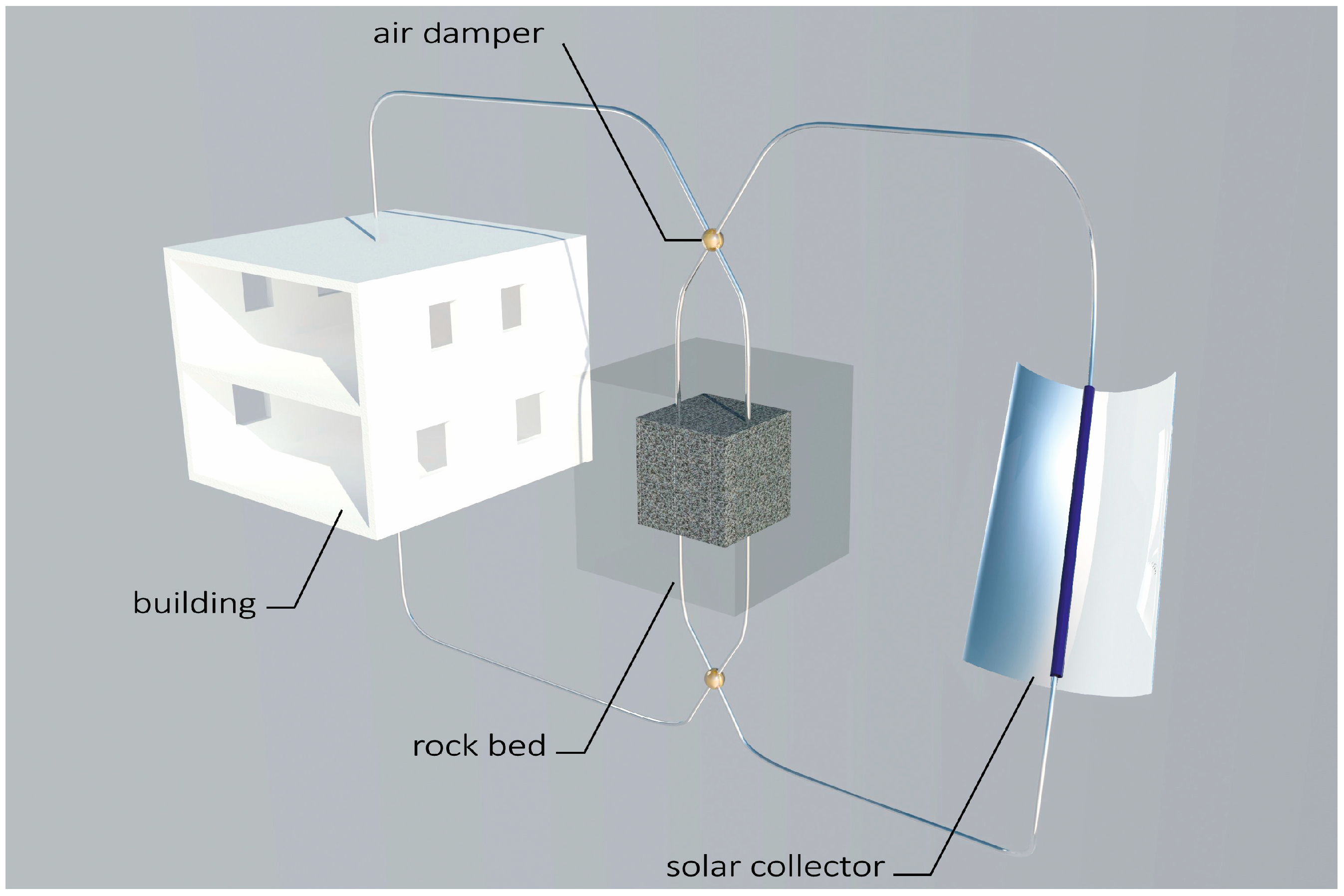
  • Section 2 describes the selection of the main components of the system in the form of a solar collector and a heat accumulator.
  • Section 3 describes the possibilities of integrating the collector with a bed storage and a building. The criteria of assessing the integration method are then introduced and refer to its impact on architecture and functionality.
  • Section 4 describes the influence of the location of the system on the energy performance of the building. Energy analyses of the solar heating system operation over the year are then presented for the three extreme variants of integration. It allows the exact dimensions of the system to be chosen and visualizations of real buildings to be created.

2. Materials and Methods

The considered heating system is made of two main components: a solar collector and rock bed storage (Figure 1). The working medium in the whole system is air, which after being heated in the solar collector is directed to either the rock bed storage or directly to the rooms of the building. During the night, as well as days with low insolation, heating of the interior takes place due to discharging of the bed storage. Depending on the location of the bed in relation to the building, it is also possible to use its heat losses for heating purposes.
To date, the authors have conducted a lot of research in order to verify the correctness of the conceptual heating system. The verification stages are presented in detail in [23]. Within the framework of theoretical and experimental research, three test stands were built. The analytical model of a concentrating collector with internal ribbing was described in [24], while its experimental tests were presented in [25]. The model of the bed storage is included in [26], whereas tests of the cooperation of the collector and the bed storage, and results of simulation of the annual work of the system, are included in [23]. The principle of the operation of the solar heating system is shown schematically in Figure 2. The model operates with an hourly step using available meteorological data for a given location and by taking into account the angle towards the sun. The calculations were made using Mathcad 15 software and a spreadsheet with appropriate conditional formulas.

2.1. Solar Collectors—Selection of the Type of Collector

Various types of solar collectors can be used for the operation of the analyzed energy system. Concentrating collectors, which only use direct solar radiation, are necessary in order to create high temperatures. This will allow a year-round operation of the system in the climatic conditions of Central Europe. These collectors require tracking the Sun’s movement and following it in one or two planes of rotation. Because of the simplicity of constructing the moving parts of the collector, especially the air channel connections, it was decided to consider only linear concentrating collectors. In the case of a uniaxial tracking system, collectors with vertical, horizontal, and inclined axes of rotation, which are shown in Figure 3, can be distinguished.
From the dataset of the typical meteorological year (TMY) for Wroclaw (Poland), which was developed on the basis of meteorological measurements that were conducted in the years 1971–2000 [27], data on direct solar radiation for each hour of the year were used. On this basis, calculations of the simulations of the amount of direct solar energy that is available for each of the three variants of the uniaxial tracking system were conducted. Analysis showed that 479, 413, and 398 kWh for each m2 of the area of the concentrator’s aperture were available for a vertical, horizontal, and inclined axis of rotation throughout the year, respectively. In the case of an inclined axis, an optimal angle of 67° for the whole year for Wroclaw, for which the amount of available energy is the highest, was determined with the aid of computational experiments. The amount of available energy for each month of the year is shown in Figure 3. The largest amount of energy is available for the collector with a vertical axis of rotation. However, the calculations assumed the full azimuthal rotation of this collector and a total lack of objects covering the Sun, such as trees and buildings. In practice, such a location of the installation would be very difficult to achieve. It would also be impossible to build a housing estate using such installations. Therefore, a collector with a horizontal axis of rotation, which is set in the direction of the southern azimuth, was chosen for further project work. Its advantage is that it has the smallest sensitivity to the occurrence of objects covering the Sun, as well as many possibilities of integration with a building’s structure.

2.2. Rock Bed Storage—Selection of Filling Material

Permanent phase storage materials are characterized by their large variety of thermal parameters. They affect the size of the bed storage and, thus, the investment cost. The volume of the bed is an important parameter when designing seasonal installations because it should be taken into account during the design and construction phases of a building. The selected material properties are included in Table 1. The average market price offered by suppliers in Poland was considered for the materials in the table, including pebbles. The authors of the work performed a comparative analysis of potential bed storage filling materials while taking into account their density, specific heat, and unit price.
As can be seen in Table 1, building materials have the highest specific heat and filling factor among the analyzed materials. The bed storage made of brick is easy to execute and structurally stable. However, the comparison of unit costs showed that the bed made of brick is several times more expensive than the one made of natural stone. An important parameter is also volumetric specific heat, which is one of the basic parameters that determine the size of a bed storage. The summary of unit costs and specific heat showed that aggregate can be a better material for long-term heat accumulators. Crushed granite, which was selected for further analysis, has good accumulative properties, is cheap, and is also easily available in Lower Silesia.

3. The Impact of Integration on the Architecture and Functionality of a Building

Research on energy-saving houses created in the years 2005–2018 shows [30] that there are various and fragmented layouts of houses, including line forms, one-story bungalows, two-story buildings, as well as other mixed ones like H-shaped houses. These systems are often enriched with greenhouse systems that act as thermal buffers with various utility functions.
In today’s sustainable design, and by using the integrated design process, architects go beyond their discipline of knowledge, and in cooperation with other branches, create energy and environmentally friendly architecture [31]. In typical on-grid houses, designers are confronted with the problems of obtaining solar energy, balancing heat gains and losses, and ensuring both comfort of use and attractive architectural form. In self-sufficient energy houses, the issue of solar energy storage is of additional importance.
The presented building/collector/bed storage system offers many opportunities for the creation of original spatial variants of 21st century architecture for fully off-grid houses. A two-story building with a flat roof, on a plan similar to a square and with a usable area of 110 m2, was selected for analyses due to its favorable ratio of the surface of the external partitions to its cubage. It is one of the most widespread types and dimensions of modern detached single-family housing in Poland, and it has the highest potential for the implementation of research results.
For the execution of the spatial models of variants of integrating the solar heating system with the house, a collector with a horizontal axis of rotation with dimensions of 3.0 × 6.0 m, and a bed storage with dimensions of 2.5 × 2.5 × 2.5 m and with 1.0 m of insulation, was considered. For better illustration of the research problem, integrations of the collector and the bed storage are shown separately.

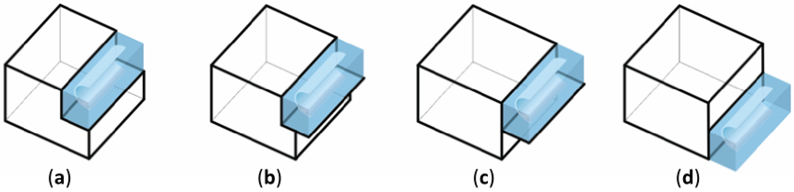
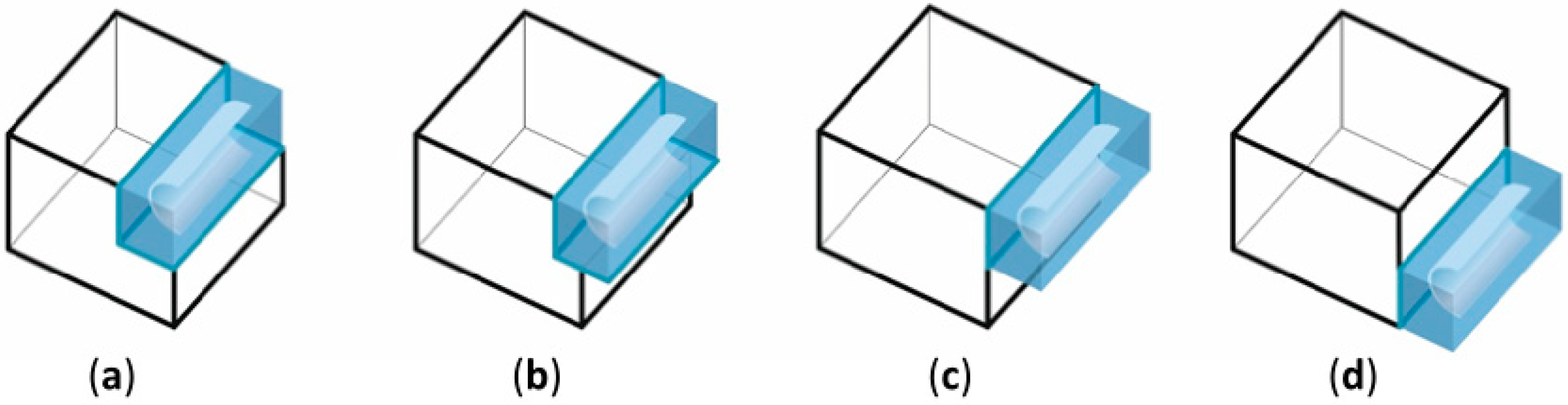
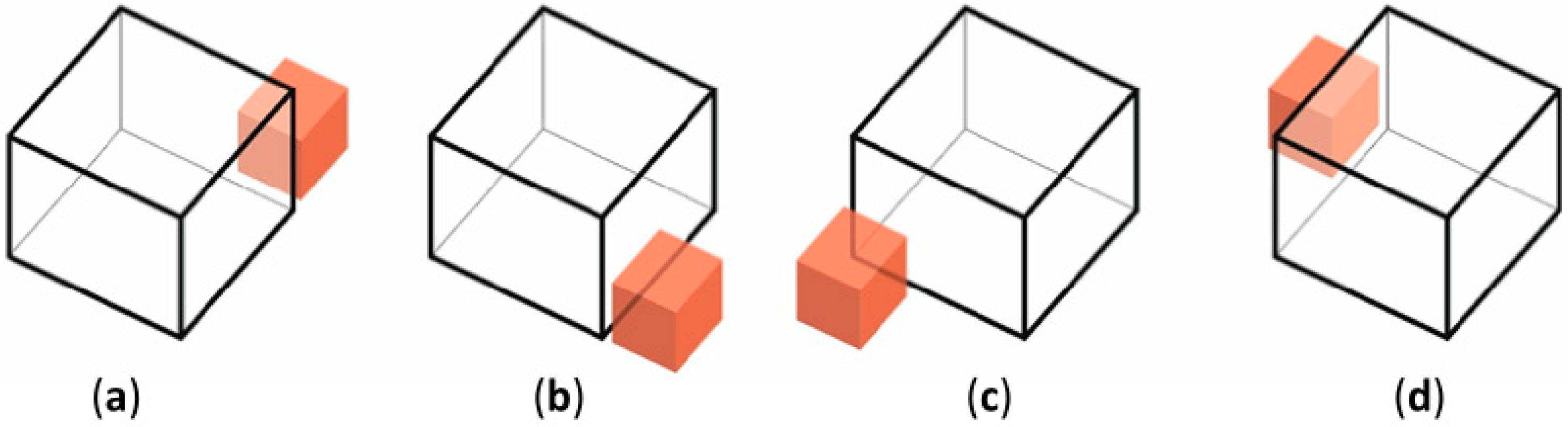
3.1. Integration of the Solar Collector with the Building

For utility reasons, the collector is placed in a glass casing that has a high transmission of solar radiation and a steel post-and-beam facade structure. The horizontal elements of the collector’s casing have a minimum slope of 8% that allows for drainage of rainwater. The criterion of optimal solar radiation of the collector was considered in each system.
Three stages of integrating the collector with the house were distinguished, which were developed in seven different categories and shown as the selected 23 variants. The first variant assumes no integration, and the collector is offset from the house. The second variant considers a small degree of integration, and the collector is placed next to the building from the south in vertical and horizontal arrangements. In the vertical arrangements, it is attached to the facade at either the ground floor level (Figure 4a) or the floor above, and may have additional functions (e.g., forming a roof above a terrace) (Figure 4b). In the horizontal arrangements, the collector with its casing diffuses the facade to varying degrees, from complete coverage to small coverage (Figure 5a–c).
A third and greater degree of integration occurs when the collector with its casing is integrated into the building structure and the living space of the house. The collector’s casing may be partially replaced by the house wall or partially removed. It can occur in several variants.
In the first variant, the integration of the collector with the building’s structure takes place on one floor, has a variable depth of penetrating the interior, and is neutral for it. Separation can take place with the use of a full partition (i.e., a wall and a floor or ceiling), and the collector is then combined with the house to a greater or lesser extent (Figure 6a–d). Analogous separation can also be done using glazing, which additionally illuminates the rooms (Figure 7a–d).
In the second variant, the integration of the collector is not only solid, but it is also in the functional layout of the interior, which is even affected by its exposure on two floors. This may occur in various configurations of the collector’s location (Figure 8a–d). The collector’s casing is used as an added space (e.g., in the form of a winter garden), and it is possible to expand in various layouts (Figure 9a–c).
In the last variant, the integration of the collector is inside the building, and there is a total or partial elimination of its casing. The collector becomes an important element of the interior’s furnishing and determines the space of the house (Figure 10a–c).

3.2. Assessment of the Integration of the Solar Concentrating Collector with the Building

An assessment of the integration of the solar concentrating collector with the building was made with regards to architectural (a–h) and functional issues (i–k), comfort of using the house (l–m), and also the operation of the collector (n–o), and these are included in Table 2. Seven significantly different cases of integrating the building with the collector from the above specifications were selected for comparative analysis (i.e., 4a with 5a, 4b with 5b, 6a, 7d, 8a, 9a, and also 10c). A plus symbol in the table is placed if the criterion was possible to achieve for a given integration variant, while a minus symbol is used when the proposed solution precluded the possibility of fulfilling the criterion.
Fifteen criteria were distinguished with regards to the evaluation of the collector’s integration. The analyzed variants were met for a range of 5 to 12 criteria. According to the analysis, each variant of the collector attached to the building met some of the criteria. As the collector took more space inside the building, the number of fulfilled criteria increased. However, it is impossible to meet all of the criteria at the same time.

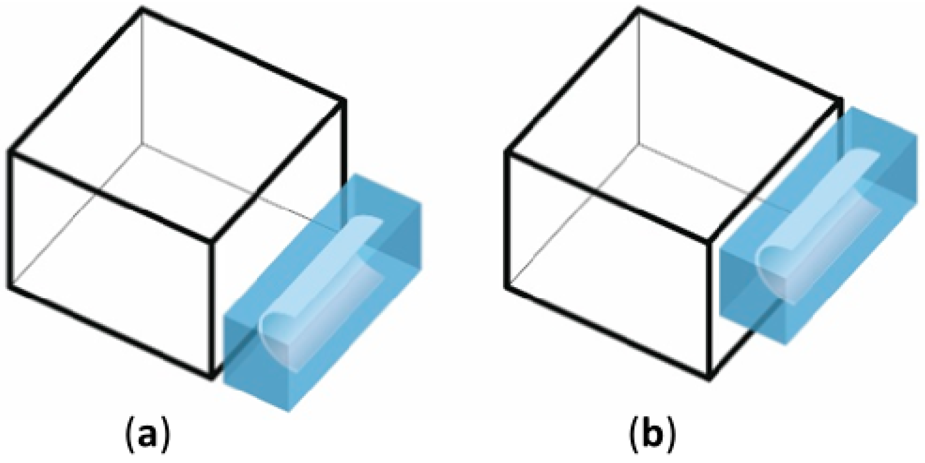
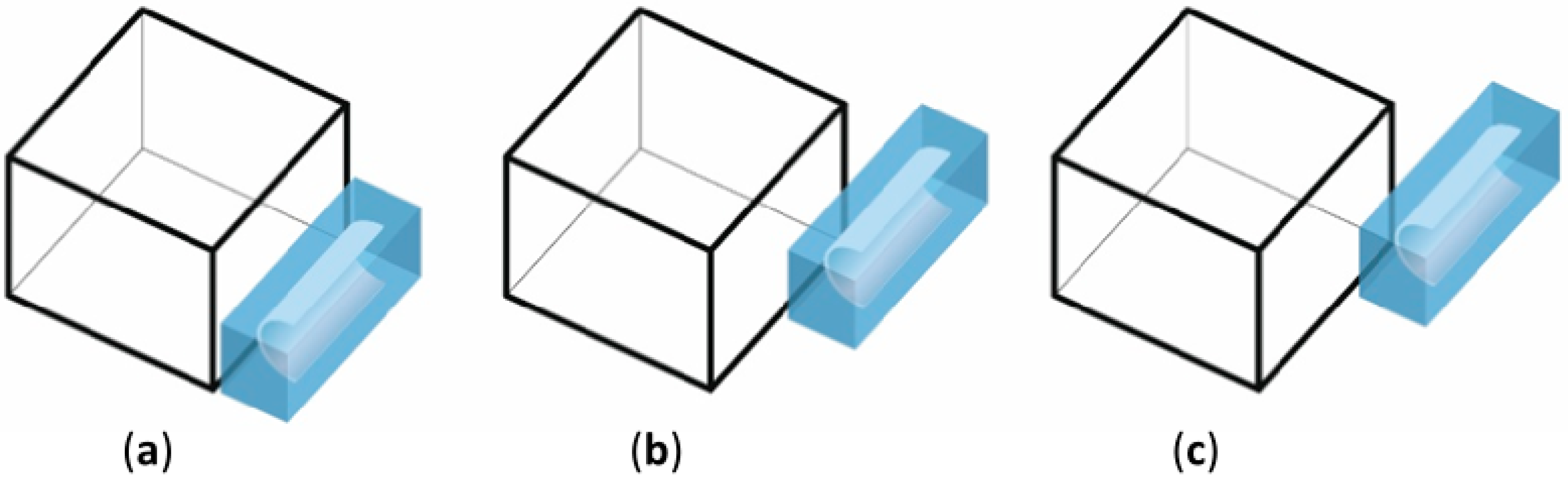
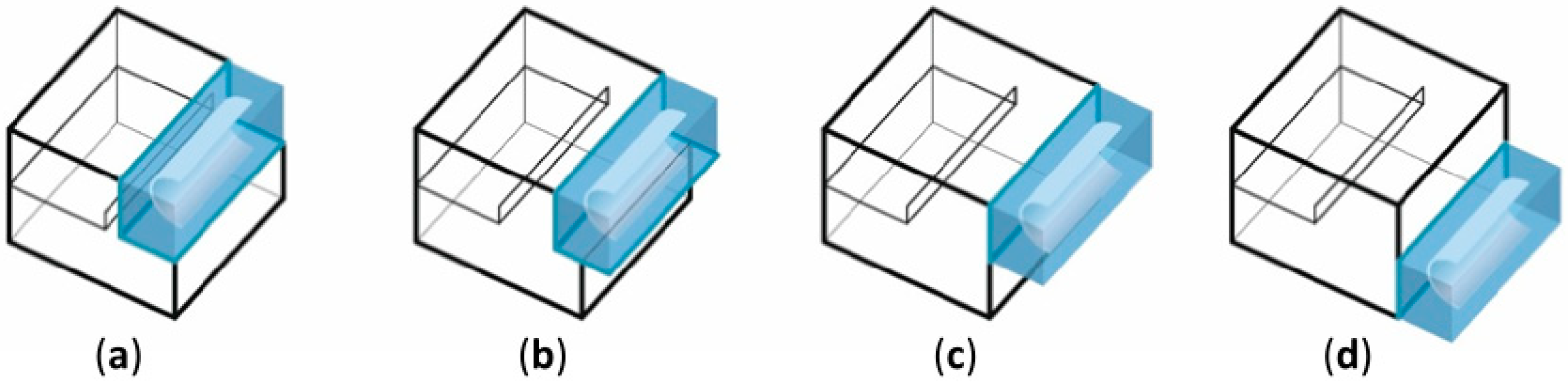
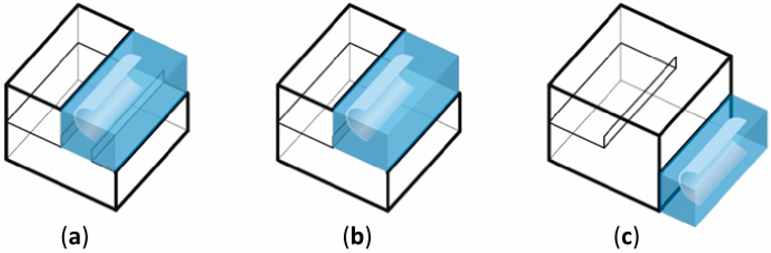
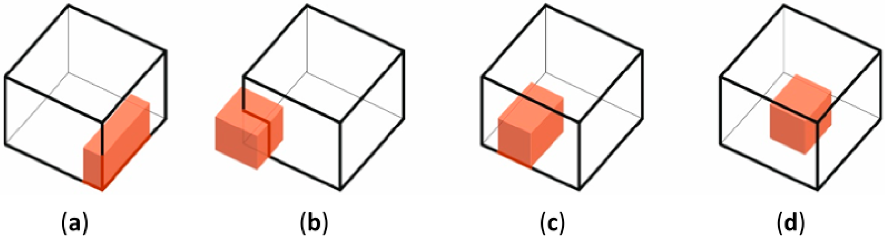
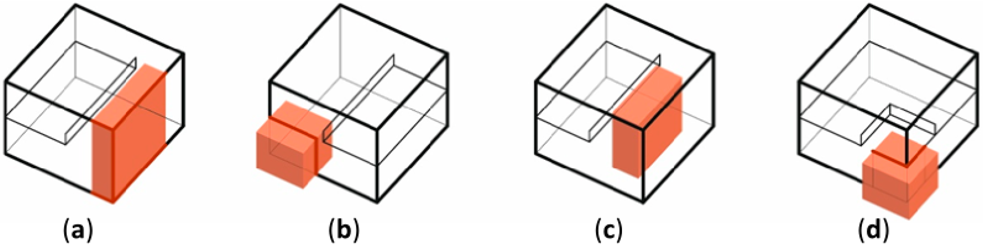
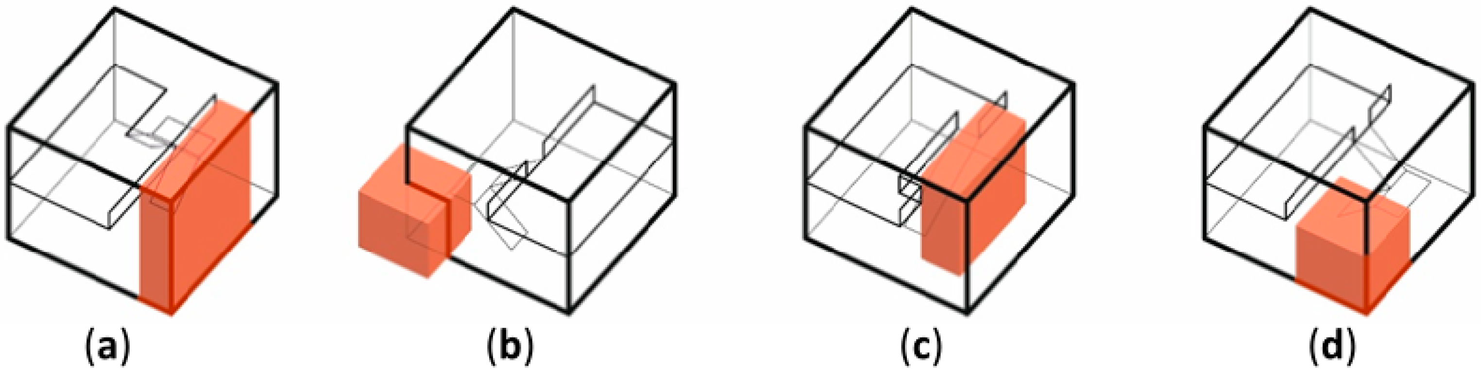
3.3. Integration of the Bed Storage with the Building

The bed storage is located inside a casing made of insulating material that is adapted for use outside or inside the building. Its finish depends on the degree of integration with the house. Due to the weight of the bed storage, it is located on the ground floor or embedded in the ground. The shape of the bed storage is influenced by its location and is either close to the size of a cube or fits into the dimensions of the house. A service zone is planned for the bed storage.
Four degrees of integrating the house with the bed storage were distinguished, which were developed in six categories and shown as the selected 22 variants. The first degree correlates with no integration; the bed storage is away from the house and the service zone is located somewhere near the bed storage. The second degree indicates a small degree of integration; the bed storage is added to the building in horizontal layouts, which is possible in any place and on any facade on the ground floor of the house (Figure 11a–d). The service zone is located outside the house.
In the third degree, there is integration between the bed storage that is embedded in the ground and located either directly under the house or under the collector. In both cases, the service zone is inside the house (Figure 12).
The last degree of integration correlates to the case when the bed storage is incorporated into the building structure and the living space of the house. The bed storage may be neutral for the layout of the house, or exposed. There are several variants that differ in shape and location within the ground floor of the building.
In the first variant, the integration of the bed storage can be inside the building in any location on the ground floor, and it is neutral for its projection. The bed storage may be adjacent to the side of the house, partially extended beyond the outline of the ground floor, or may be located in the center of the building forming a stratigraphic arrangement of rooms. In all cases, it takes any shape that is elongated or similar to a square (Figure 13a–c). The bed storage can also occupy two floors of the building in analogous configurations (Figure 14a–c).
In the second variant, the integration of the bed storage is not only in the solid of the building, but is also exposed in the functional layout of the interior on two floors. It can occur in various configurations and sizes, while creating open interior layouts. As was the case in the previous example, the shape of the bed storage can be adjusted to the dimensions of the building or have an optimal shape of an equilateral cube (Figure 15a–d).
In the last variant, there is a functional integration of the bed storage. The bed storage becomes an important functional element and determines the space of the house. It can be directly or indirectly connected to the staircase, and the area of the bed storage becomes the added space to the interior of the house in a vertical or horizontal arrangement (Figure 16a–c).

3.4. Evaluation of the Integration of the Bed Storage with the Building

The evaluation of the integration of the bed storage with the building in the form of Table 3 was made with regards to architectural (a–m) and functional issues (n–p), comfort of using the house (q–r), and also the operation of the bed storage (s–t). For comparative analysis, as was the case with the collector, the most specific seven different variants were selected from the included specifications (i.e., 11a, 12a, 12b, 13a, 13d, 15a, and 16d).
Twenty criteria were distinguished with regards to the evaluation of the bed storage’s integration. The analyzed variants were met for a range of 6 to 16 criteria. According to the analysis, the variant of the bed storage attached to the building met some of the criteria. A smaller number of criteria were only fulfilled by the bed storage located under the building. As the collector took more space inside the building, the number of fulfilled criteria increased. For the bed storage located inside the building, there may be a different number of fulfilled criteria, which depends on its exposure and any increase in functionality.
The presented review indicates a multitude of variants of the integration between the collector system, the bed storage, and the building. The analysis shows that due to the size of the system and its specificity, there is no ideal integration variant that would not interfere with architecture and functionality, regardless of the fact that the heating system is combined with an existing or new building. Each investment must be treated individually. Future users of the building must choose a variant, guided by their own needs and possibilities, that are related to, for example, the shape of their land or its surroundings.

3.5. Selection of the Variant of the Integration for Further Analysis

The location of the heating system, apart from its influence on architecture and functionality, also affects the operation and energy balance of the entire building. Particularly important in this context is the location of the bed storage, which, when compared to the solar collector, gives away a lot of heat. This heat can be used if the bed storage is located inside the building, or it is lost if the bed storage only adheres to it. In addition, the location of the bed storage directly affects its size. The greater the losses to the environment, the bigger volume of bed storage is required in order to cover the heating demands throughout the heating period. The analysis of the operation of the entire system during the year requires detailed calculations that take into account the local meteorological conditions and the energy standards of the building.
Three different variants of the integration were selected for further detailed energy analysis. The first two variants concern new buildings and provide a possibility of deep integration with the building. The third one presents a proposal of the integration with an existing building. A method of integrating the system with the building was chosen as the criterion for its selection. The authors wanted to show extreme solutions and their impact on the size of the system and its operation parameters on a yearly basis. Further analysis covered:
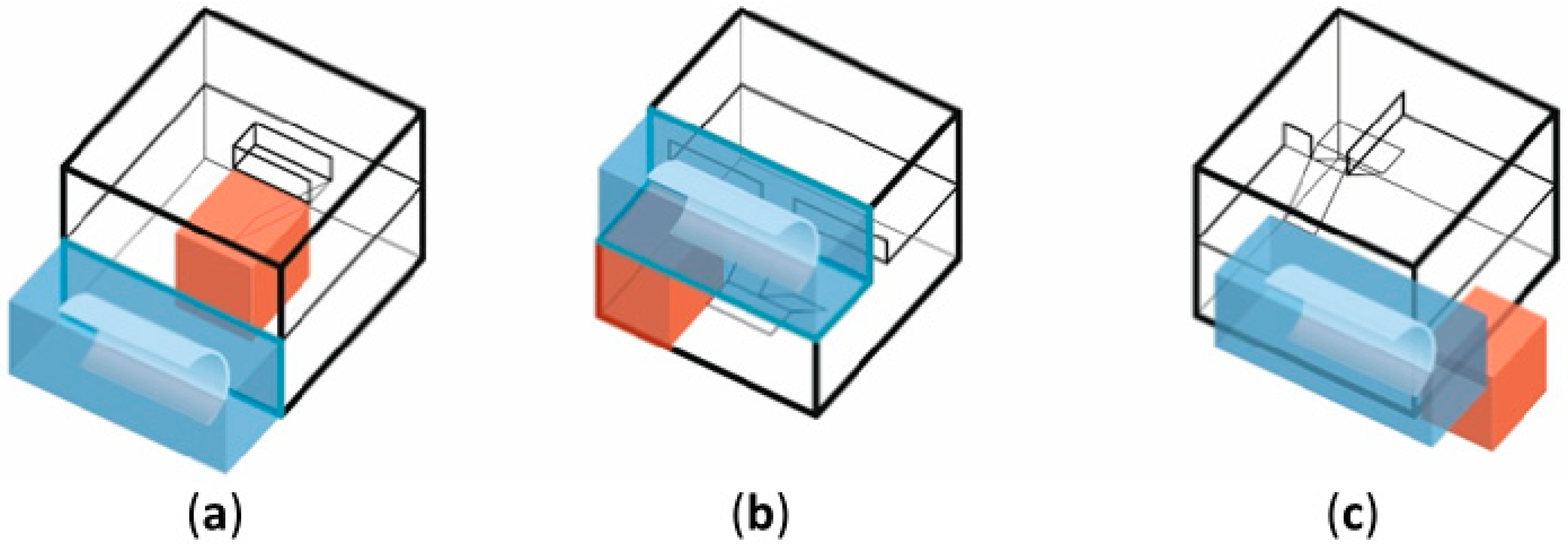
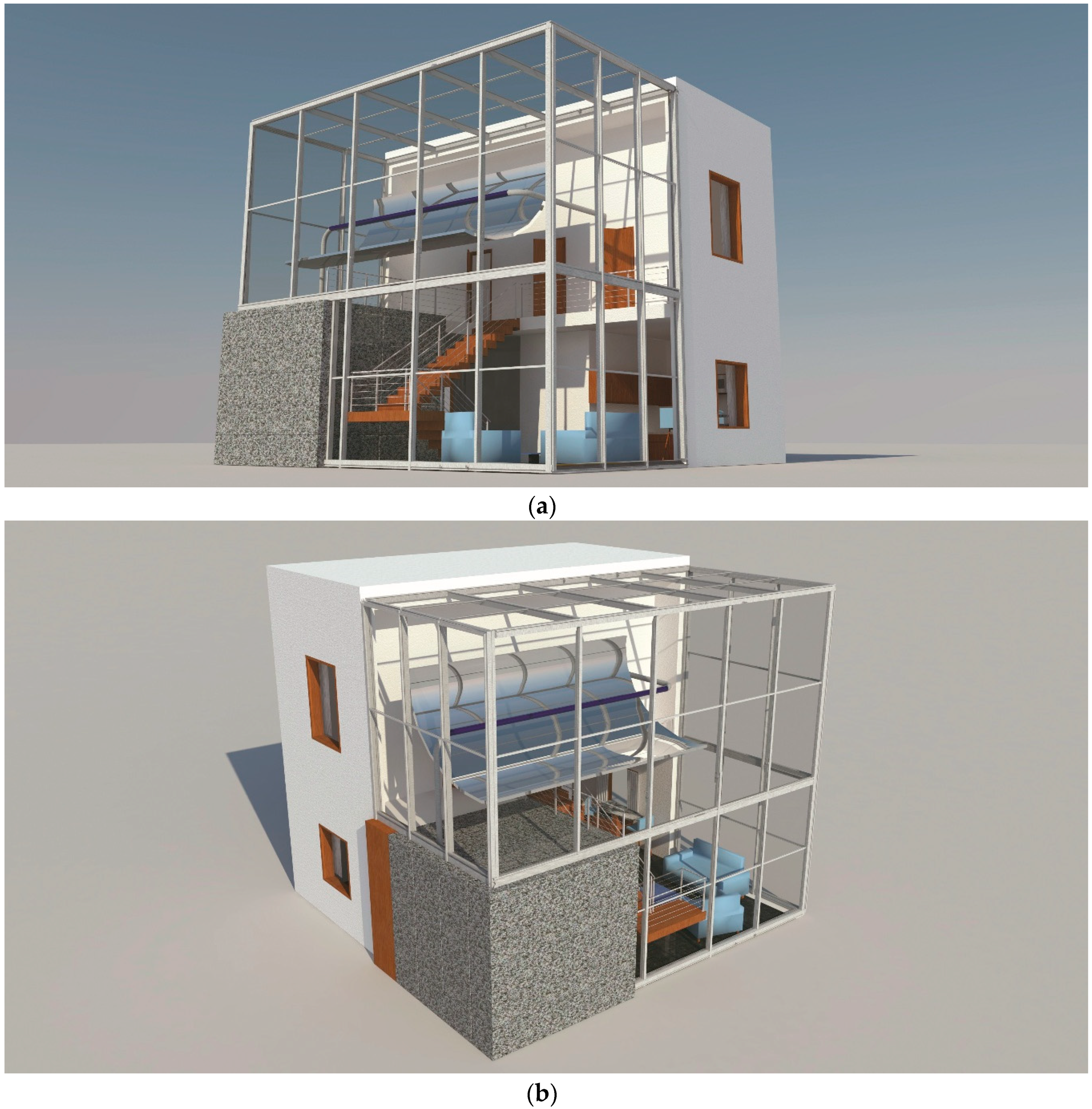
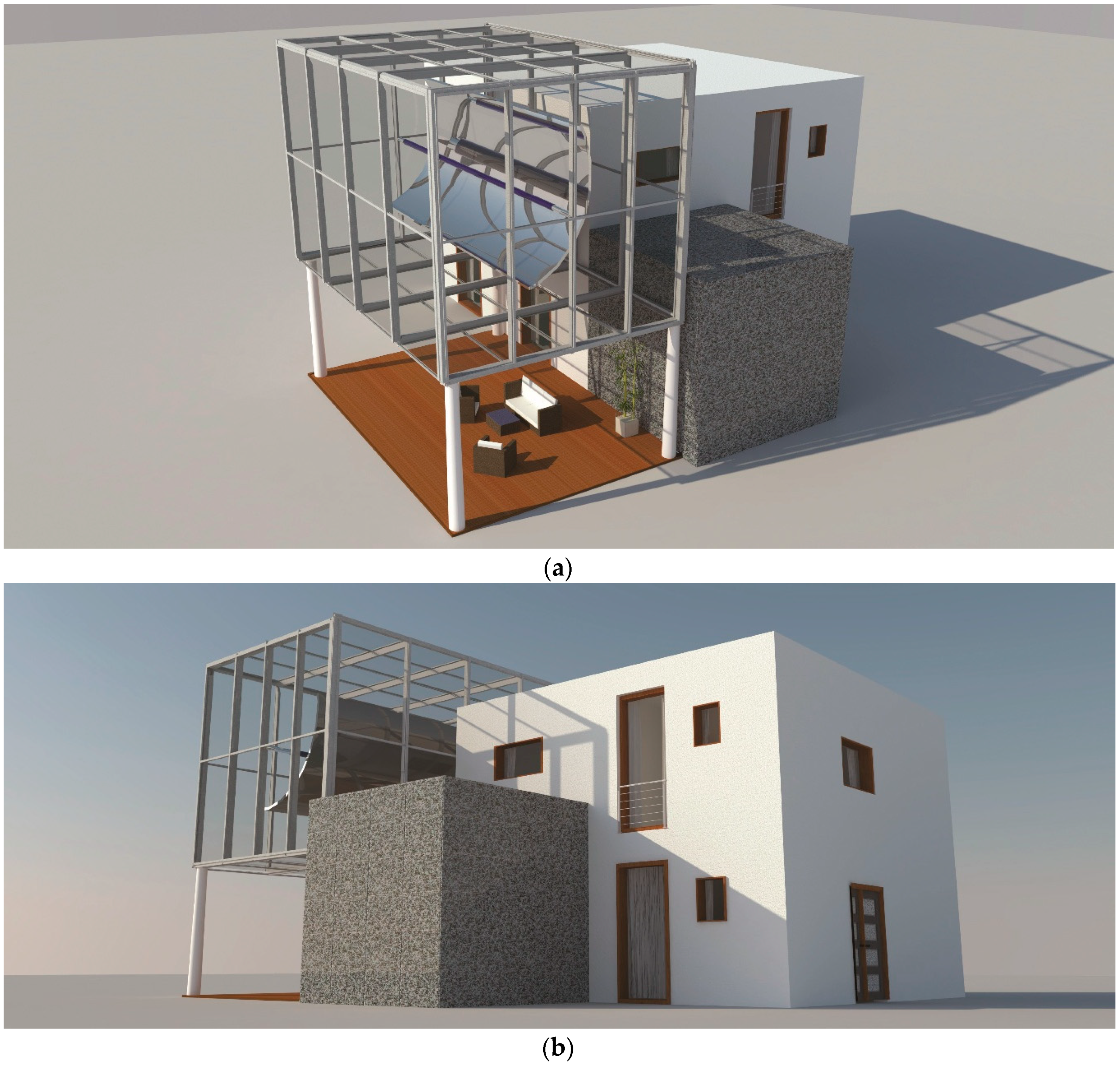
  • Variant No. 1—an object with a solar system adapted to the parameters of a typical single-family house. It includes a variant of the collector and the bed storage that are largely integrated with the building, as shown in Figure 7d and Figure 13d, called the enfilade house (Figure 17a). Such a location of the bed storage gives the greatest opportunities to use heat losses from the system. The added area with a solar collector does not limit the functionality of the facility.
  • Variant No. 2—an object that is adapted to the dimensions of the solar system, which includes a variant of the collector and bed storage that is fully integrated with the building, as shown in Figure 10b and Figure 16d, called the open space house (Figure 17b).
  • Variant No. 3—an object with typical dimensions to which a variant of small integration of the collector, the bed storage and the building was adjusted, as shown in Figure 4b, Figure 5b, and Figure 11a, called the layout with an existing house (Figure 17c).

4. Results and Discussion

The three previously described forms of integration were analyzed. Each of them assumed that the heating system covered the whole year’s heating demands of the building with an energy consumption of 15 kWh/m2·year. The adopted value was in line with the current standards of low-energy buildings and directly resulted from the technology of constructing the building, and not from the heating system. The authors adopted this assumption because it enabled the work of different systems to be reliably compared—all variants had the same reference point. The temperature inside the building was equal to 20 °C. In addition, it was assumed that the temperature of the bed storage should not be lower than 50 °C in order for the system to work correctly, in the case of a higher number of days with low solar radiation and a low ambient temperature. Calculations were made while considering meteorological data for TMY Wroclaw, which was collected in a spreadsheet. Calculations were carried out hourly. The model of the heating system’s operation, described in the second section, was adapted to the assumptions for the three discussed integration variants. It took into account the flux of heat losses from the accumulator to the building, to the surroundings, and the ground. Because of the considerable size of the bed storage, the thickness of its insulation in each case was assumed to be 1 m. In each of the three variants, the amount of lost energy could be used to cover the heating demands, which is discussed in more detailed below. Lower usage of the losses made it necessary to use a collector with a larger mirror area and a larger volume of bed storage. The selection of the size of the elements was performed iteratively in order to meet the assumption regarding the minimum temperature in the bed storage, which was mentioned above. Detailed data for the selected collectors and rock bed storages are shown in Table 4.
The annual analysis of the cooperation between the collector and the bed storage enabled the temperature of the bed storage to be determined as a result of the following: the energy supply from the collector, heat losses from the accumulator, and discharging of the bed storage for the purpose of covering heating demands. In each of the analyzed variants, the distance between the solar collector and the rock bed storage was not large. It was assumed that losses in air ducts would be compensated by insulating the conduits, as is the case in other heating systems. Figure 18 presents the changes in temperature of an accumulative material for the three considered cases and the direct radiation that was used in the calculations.
Heat losses, depending on the location of the bed storage, were divided into internal and external. Internal losses concerned those surfaces of the bed storage that were inside the building, which were, for the first variant, all sides of the bed storage; for the second variant, two sides including the bottom and top of the bed storage; and for the third variant, only one side of the bed storage. External losses in the first case did not occur, in the second case concerned two sidewalls of the bed storage, while in the third case they concerned three outer walls together with the top of the bed storage and losses to the ground. Figure 19 presents individual losses for all the variants, which are marked and summarized in the form of pie charts. The annual analysis shows that losses to the inside of the building for the enfilade house constituted 100%; for the open space house, losses to the inside of the building constituted 65%, while external losses amounted to 35%; and for the last variant, the existing house, internal losses constituted only 16%, while external losses, which consist of losses generated by the sides and the top of the rock bed storage, amounted to 67% as well as losses to the ground that amounted to 17%. In this case, the total of external losses was the highest, which makes it necessary to use the largest rock bed storage and the largest solar collector, as indicated in Table 4.
The above-mentioned heat losses gave different possibilities of usage in the case of the three integration variants. The first variant of the enfilade house experienced the greatest use of heat losses from the bed storage because the accumulator was located completely inside the building. In the variant of the open space house, the heat flux from two lateral surfaces was transferred to the surroundings. In the third and least integrated variant, it was only possible to use the heat loss flux from the bed storage for one of the sidewalls. The heat flux from the other three sides and top surfaces was transferred to the surroundings and from the bottom surface to the ground.
Figure 20 shows the daily heating demands of the building and heat losses that were used to cover these demands for the three analyzed variants. As shown in Figure 20, in the enfilade house that had the bed storage located completely inside the building, the losses from the bed storage almost totally covered the heating demands of the building in spring and autumn. During the year, the heat losses from the accumulator covered 78.32% of all demands. This caused a smaller discharging of the bed storage, which resulted in low energy expenditure on the fan’s operation. The bed storage was discharged mainly in winter. A similar situation occurred in the open space house because the differences in losses only resulted from the heat flux transmitted to the surroundings from the surfaces of two sidewalls. Coverage of the heating demands with the heat losses from the accumulator was equal to 61.32%. The lowest use of heat losses from the bed storage for covering the demands was in the case of the existing house, and it amounted to only 23.84%. As a result, there was a necessity to use almost twice as big a bed storage when compared to the two previous variants. The size of the solar collector’s mirror also had to be 50% larger when compared to the enfilade house. In the last variant, there was no need to remove heat to the surroundings from the room in which the accumulator was standing.

The Final Appearance of Buildings with an Integrated Heating System

After conducting the energy analysis, an attempt was made to visualize selected solutions, while taking into account the real dimensions of both the building and the solar heating system.
Variant No. 1—the enfilade house (Figure 21a,b), in which the solar system was adapted to the parameters of a typical single-family house. The functional system is of the atrial type with the enfilade distribution of rooms around the centrally located bed storage. The collector is situated next to the south facade on the ground floor of the house and is integrated to a small extent with the solid of the building. It is separated by a transparent partition from the interior of the house. The layout of rooms on the ground floor enables indirect lighting of the interior through the collector’s casing. The bed storage with insulation has the same height as the ground floor and determines the interior of the house. It can be additionally exposed by changing the finishing material of the cover. Both the collector and the bed storage are easily accessible for service purposes, and the collector’s casing provides good access for periodic cleaning.
Variant No. 2—the open space house (Figure 22), in which the object is fully integrated and adapted to the dimensions of the solar system. The house has a functional layout that is influenced by the full exposure of the collector located inside the house. It is on the first floor and in an open space without casing. The layout of the rooms on both floors is adapted to the system of the collector and uses the possibility of direct lighting. The bed storage is of optimal size and touches two external walls. It can be additionally exposed by a change in the finishing material of the cover. The collector and its casing require additional installations in order to provide access for periodical cleaning. The location of the bed storage allows easy access for service purposes.
Variant No. 3—the existing house (Figure 23), in which the collector and bed storage are added to a building with typical dimensions. The house has a standard functional layout that faces south. The collector is attached to the southern facade on the first floor and partially covers the facade. Adjacent rooms have decreased daylight due to the fact of indirect lighting. On the other hand, an additional space for the roofed terrace is created under the collector. The bed storage is placed next to the eastern facade and completely covers part of it. In a neighboring room there may be a partial decrease of daylight depending on the presence of windows. The collector and the bed storage are easily accessible for service purposes, and access to the collector’s casing is not really difficult.

5. Conclusions

The article presents multi-stage analyses of the integration of an all-year solar heating system with a building. Due to the number of possible configurations, the analysis was divided into that of the integration of the collector, as well as the heat accumulator. Twenty-three variants of integration of the collector and 22 variants of integration of the bed storage were characterized. Based on the conducted detailed analyses, it was found that:
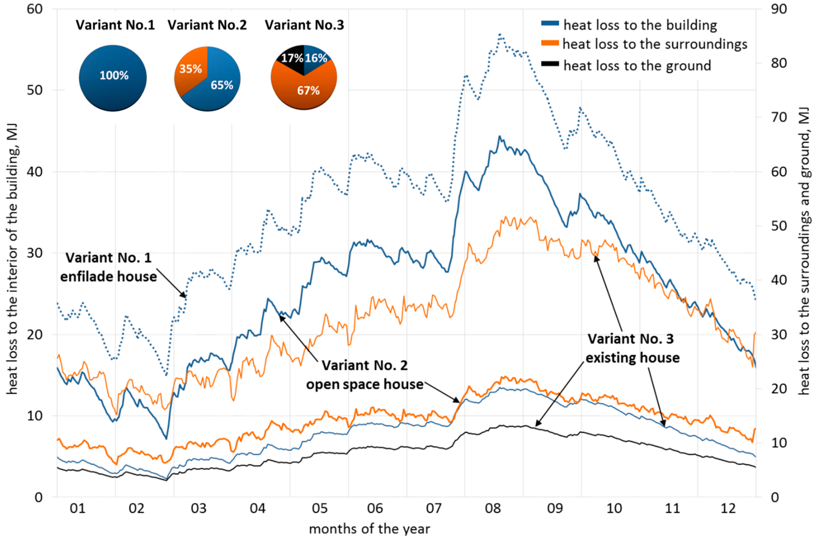
  • The conducted analysis of the integration shows that the location of the heating system, apart from its influence on architecture and functionality, also strongly affects the operation and energy balance of the entire building.
  • There is no universal variant of integrating the system with a new or existing building. However, the highest degree of integration can be obtained for objects that are in the design phase. It is possible to fully use and reduce heat losses from the system, while at the same time keeping the smallest sizes of solar collector and heat accumulator.
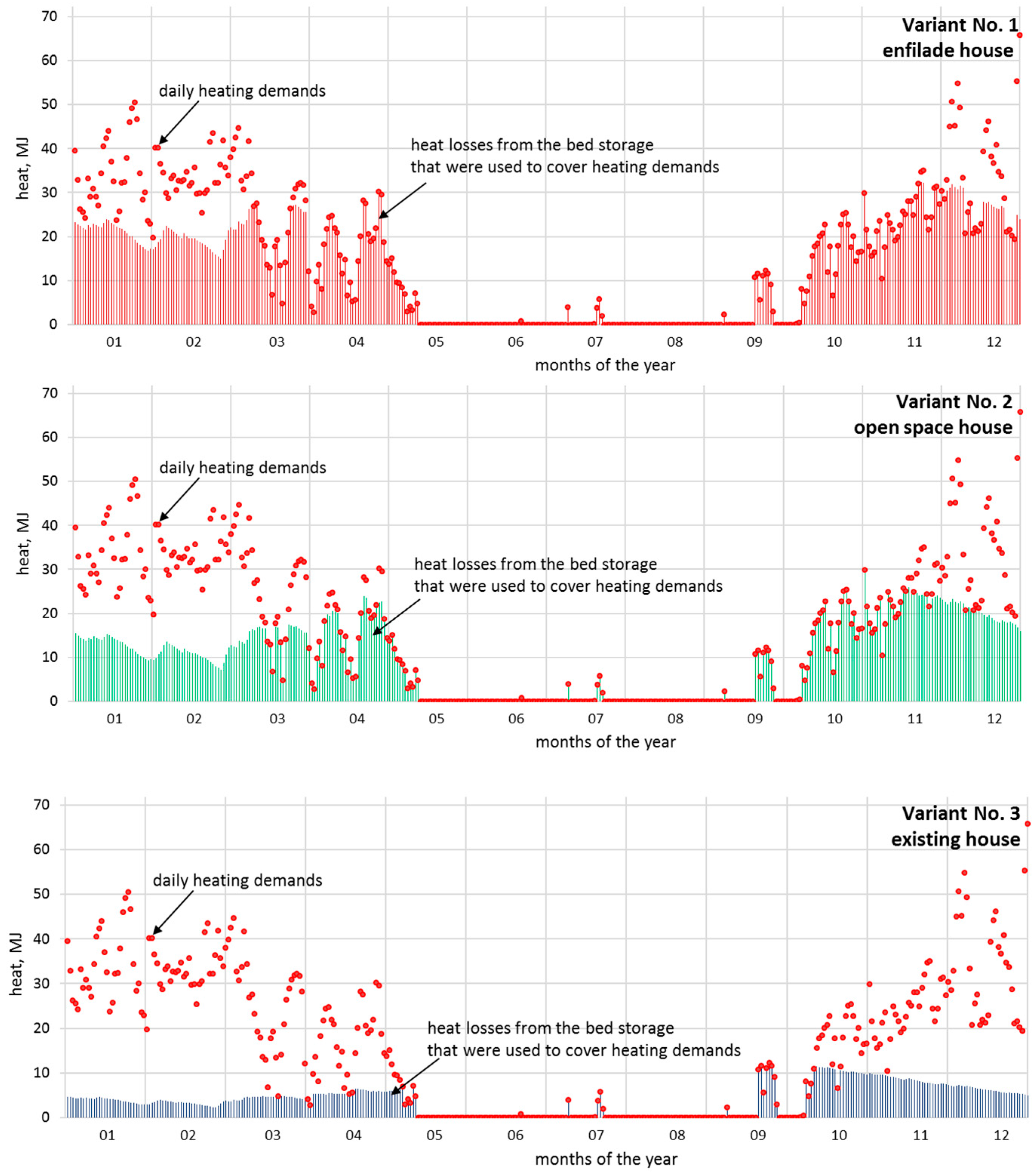
  • Variant 1, in which the bed storage is located inside the building, was characterized by the covering of the heating demands with heat losses from the bed storage at the level of about 80%. In variant 2, in which the bed storage was placed in the corner of the building, the covering of the heating demands by heat losses from the bed storage was equal to about 60%, and in the last variant, in which the bed storage was placed next to the building, by about 25%.
  • Analyses have shown that the degree of integration of this system with the building’s body determines the size and power of the installation. This allows the authors to state that the presented installation can be used in climatic conditions similar to Poland.

Author Contributions

Conceptualization, A.B., M.N., and A.N.; methodology, A.B., M.N., and A.N.; validation, M.N.; investigation, A.N. and M.N.; resources, M.N.; data curation, A.N. and M.N.; writing—original draft preparation, M.N. and A.B.; writing—review and editing, M.N. and A.B.; visualization, A.B.; supervision, M.N.; project administration, M.N. and J.K.; funding acquisition, A.B., M.N., and J.K.

Funding

This research was funded by the Ministry of Science and Higher Education in Poland within the grant for Wrocław University of Science and Technology. Project No. 0402/0157/17, 0401/0205/17 and 0402/0171/18.

Conflicts of Interest

The authors declare no conflict of interest.

References

  1. Solar Heat Europe. Available online: http://solarheateurope.eu (accessed on 24 June 2019).
  2. REN21. Renewables 2019 Global Status Report (Paris: REN21 Secretariat); REN21: Paris, France, 2019; ISBN 978-3-9818911-7-1. [Google Scholar]
  3. Benemann, J.; Chehab, O.; Schaar-Gabriel, E. Building-integrated PV modules. Solar Energy Mater. Solar Cells 2001, 67, 345–354. [Google Scholar] [CrossRef]
  4. Benemann, J.; Fitzgerald, M.C.; McCabe, J. Adv. Sol. Energy 1999, 13, 317.
  5. Hu, Z.; He, W.; Ji, J.; Zhang, S. A review on the application of Trombe wall system in buildings. Renew. Sustain. Energy Rev. 2017, 70, 976–987. [Google Scholar] [CrossRef]
  6. Bellos, E.; Tzivanidis, C.; Zisopoulou, E.; Mitsopoulos, G.; Antonopoulos, K.A. An innovative Trombe wall as a passive heating system for a building in Athens—A comparison with the conventional Trombe wall and the insulated wall. Energy Build. 2016, 133, 754–769. [Google Scholar] [CrossRef]
  7. Elinwa, U.K.; Radmehr, M.; Ogbeba, J.E. Alternative Energy Solutions Using BIPV in Apartment Buildings of Developing Countries: A Case Study of North Cyprus. Sustainability 2017, 9, 1414. [Google Scholar] [CrossRef]
  8. Ghosh, A.; Norton, B. Advances in switchable and highly insulating autonomous (self-powered) glazing systems for adaptive low energy buildings. Renew. Energy 2018, 126, 1003–1031. [Google Scholar] [CrossRef]
  9. Hestnes, A.G. Building Integration of Solar Energy Systems. Sol. Energy 1999, 67, 181–187. [Google Scholar] [CrossRef]
  10. Maurer, C.; Cappel, C.; Kuhn, T.E. Progress in building-integrated solar thermal systems. Sol. Energy 2017, 154, 158–186. [Google Scholar] [CrossRef]
  11. Munari Probst, M.C.; Roecker, C. Towards an improved architectural quality of building integrated solar thermal systems (BIST). Sol. Energy 2007, 81, 1104–1116. [Google Scholar] [CrossRef]
  12. Shen, J.; Zhang, X.; Yang, T.; Tang, L.; Cheshmehzangi, A.; Wu, Y.; Huang, G.; Zhong, D.; Xu, P.; Liu, S. Characteristic study of a novel compact Solar Thermal Facade (STF) with internally extruded pin–fin flow channel for building integration. Appl. Energy 2016, 168, 48–64. [Google Scholar] [CrossRef]
  13. Hassan, M.M.; Beliveau, Y. Modeling of an integrated solar system. Build. Environ. 2008, 43, 804–810. [Google Scholar] [CrossRef]
  14. Yang, Y.; Wang, Q.; Xiu, D.; Zhao, Z.; Sun, Q. A building integrated solar collector: All-ceramic solar collector. Energy Build. 2013, 62, 15–17. [Google Scholar] [CrossRef]
  15. Motte, F.; Notton, G.; Cristofari, C.; Canaletti, J.-L. Design and modelling of a new patented thermal solar collector with high building integration. Appl. Energy 2013, 102, 631–639. [Google Scholar] [CrossRef]
  16. Shao, J.; Chen, H.; Zhu, T. Solar Energy Block-Based Residential Construction for Rural Areas in the West of China. Sustainability 2016, 8, 362. [Google Scholar] [CrossRef]
  17. Lamnatou, C.; Mondol, J.; Chemisana, D.; Maurer, C. Modelling and simulation of Building-Integrated solar thermal systems: Behaviour of the system. Renew. Sustain. Energy Rev. 2015, 45, 36–51. [Google Scholar] [CrossRef]
  18. Chemisana, D.; Rosell, J.; Riverola, A.; Lamnatou, C. Experimental performance of a Fresnel-transmission PVT concentrator for building-façade integration. Renew. Energy 2016, 85, 564–572. [Google Scholar] [CrossRef]
  19. Hastings, S.R.; Morck, O. Solar Air System, A Design Handbook; James&James, IEA: London, UK, 2000. [Google Scholar]
  20. Sonnenhaus Institut e.V. Available online: www.sonnenhaus-institut.de (accessed on 20 June 2018).
  21. Sweet, M.L.; McLeskey, J.T., Jr. Numerical simulation of underground Seasonal Solar Thermal Energy Storage (SSTES) for a single family dwelling using TRNSYS. Sol. Energy 2012, 86, 289–300. [Google Scholar] [CrossRef]
  22. Hailu, G.; Hayes, P.; Masteller, M. Seasonal Solar Thermal Energy Sand-Bed Storage in a Region with Extended Freezing Periods: Part I Experimental Investigation. Energies 2017, 10, 1873. [Google Scholar] [CrossRef]
  23. Nemś, M.; Kasperski, J.; Nemś, A.; Bać, A. Validation of a new concept of a solar air heating system with a long-term granite storage bed for a single-family house. Appl. Energy 2018, 215, 384–395. [Google Scholar] [CrossRef]
  24. Kasperski, J.; Nemś, M. Investigation of thermo-hydraulic performance of concentrated solar air-heater with internal multiple-fin array. Appl. Therm. Eng. 2013, 58, 411–419. [Google Scholar] [CrossRef]
  25. Nemś, M.; Kasperski, J. Experimental investigation of concentrated solar air-heater with internal multiple-fin array. Renew. Energy 2016, 97, 722–730. [Google Scholar] [CrossRef]
  26. Nemś, M.; Nemś, A.; Kasperski, J.; Pomorski, M. Thermo-Hydraulic Analysis of Heat Storage Filled with the Ceramic Bricks Dedicated to the Solar Air Heating System. Materials 2017, 10, 940. [Google Scholar] [CrossRef] [PubMed]
  27. Ministerstwo Inwestycji i Rozwoju, Typowe Lata Meteorologiczne i Statystyczne Dane Klimatyczne do Obliczeń Energetycznych Budynków (Ministry of Investment and Development, Typical Meteorological and Statistical Climatic Data for Energy Calculations of Buildings). Available online: https://www.miir.gov.pl/strony/zadania/budownictwo/charakterystyka-energetyczna-budynkow/dane-do-obliczen-energetycznych-budynkow-1/ (accessed on 11 July 2018).
  28. Raznjevic, K. Thermal Tables with Charts; WNT: Warsaw, Poland, 1966. [Google Scholar]
  29. Kozłowski, S. Surowce Skalne Polski, Wydawnictwa Geologiczne, [Polish Rock Materials]; Geological Publishing House: Beijing, China, 1986. [Google Scholar]
  30. Sikorski, M.; Bać, A. Review of Energy-Efficient Houses from the Years 2005–2018 in a Moderate Climate. Report No. W01/2018/S-009; Faculty of Architecture of Wrocław University of Science and Technology: Wrocław, Poland, 2018. [Google Scholar]
  31. Bonenberg, W.; Kapliński, O. The Architect and the Paradigms of Sustainable Development: A Review of Dilemmas. Sustainability 2018, 10, 100. [Google Scholar] [CrossRef]
Figure 1. Schematic diagram of the installation.
Sustainability 11 04167 g001
Figure 2. The principle of the solar heating system.
Sustainability 11 04167 g002
Figure 3. Availability of beam radiation energy for solar collectors with different types of tracking axes for each month of the year in Wroclaw, Poland.
Sustainability 11 04167 g003
Figure 4. Schematic section and model of a small integration of a collector and a house in vertical arrangements: (a) on the ground floor and (b) on the first floor.
Sustainability 11 04167 g004
Figure 5. Schematic plan and model of a small integration of a collector and a house in horizontal arrangements: (a) total coverage of the facade, (b) partial coverage, and (c) small coverage.
Sustainability 11 04167 g005
Figure 6. Schematic section and model of separating the collector with an opaque partition: (a) full insertion of the collector into the solid, (b) partial insertion, (c) ejection from the solid at the height of the floor, and (d) ejection from the solid at the ground floor level.
Sustainability 11 04167 g006
Figure 7. Schematic section and model of separating the collector with a transparent partition: (a) full insertion of the collector into the solid, (b) partial insertion, (c) ejection from the solid at the height of the floor, and (d) ejection from the solid at the ground floor level.
Sustainability 11 04167 g007
Figure 8. Scheme of integration of the collector in a functional system: (a) full insertion of the collector into the solid, (b) partial insertion, (c) ejection from the solid at the height of the floor, and (d) ejection from the solid at the ground floor level.
Sustainability 11 04167 g008
Figure 9. Scheme of integration of the collector in an added area: (a) expanding the casing vertically, (b) expanding the casing horizontally, and (c) expanding the casing horizontally with a change in the location of the collector.
Sustainability 11 04167 g009
Figure 10. Scheme of integration of the collector as the interior’s furnishing: (a) inside the house on the first floor, (b) on the first floor next to a glass facade, and (c) on the ground floor.
Sustainability 11 04167 g010
Figure 11. Schematic plan and model of a small degree of integration between the bed storage and the house: (a) partial coverage of the east facade, (b) partial coverage of the south facade, (c) partial coverage of the west facade, and (d) partial coverage of the north facade.
Sustainability 11 04167 g011
Figure 12. Schematic section, plan, and model of integrating the bed storage embedded in the ground: (a) under the house and (b) under the collector.
Sustainability 11 04167 g012
Figure 13. Schematic section, plan, and model of the location of the bed storage on the ground floor of the house: (a) the bed storage adjoins three sides of the house, (b) the bed storage adjoins two sides of the house, (c) the bed storage inside the house, and (d) the bed storage located centrally.
Sustainability 11 04167 g013
Figure 14. Scheme of the location of the bed storage on two floors of the house: (a) the bed storage adjoins three sides of the house, (b) the bed storage adjoins two sides of the house, (c) the bed storage inside the house, and (d) the bed storage located centrally.
Sustainability 11 04167 g014
Figure 15. Scheme of the exposure of the bed storage in a functional arrangement: (a) the bed storage adjoins three sides of the house, (b) the bed storage adjoins two sides of the house, (c) the bed storage inside the house, and (d) the bed storage located centrally.
Sustainability 11 04167 g015
Figure 16. Scheme of the functional use of the bed storage: (a) indirect integration with the staircase and the possibility of using the bed storage vertically, (b) indirect integration with the staircase and the use of the bed storage area on the floor, (c) full integration with the staircase in the central layout, and (d) full integration with the staircase and an open part of the building.
Sustainability 11 04167 g016
Figure 17. Comparison of the models of variants that were selected for energy analysis: (a) enfilade house, (b) open space house, and (c) existing house.
Sustainability 11 04167 g017
Figure 18. Graphs of the changes in the bed storage temperature over the year and meteorological parameters.
Sustainability 11 04167 g018
Figure 19. Distribution of heat loss from the bed storage for three building variants over a year.
Sustainability 11 04167 g019
Figure 20. Coverage of the heating demands using heat losses in the case of the three variants of integration of the system and the building.
Sustainability 11 04167 g020
Figure 21. Visualization of the enfilade house: (a) south-west side and (b) north-east side.
Sustainability 11 04167 g021
Figure 22. Visualization of the open space house: (a) south-east side and (b) south-west side.
Sustainability 11 04167 g022
Figure 23. Visualization of the existing house: (a) south-east side and (b) north-east side.
Sustainability 11 04167 g023
Table 1. Selected properties of bed storage filling materials (based on [28,29]).
MaterialBed Storage Filling FactorDensitySpecific Heat (Mass)Specific Heat (Volumetric)Material Costs
m3/m3kg/m3kJ/kg·KkJ/m3·KEuro/kg
Ceramic and constructionCeramic brick0.916200.841360.80.11
Clinker brick0.921400.841797.60.19
Chamotte brick0.921300.841789.20.39
Hollow brick1.07350.84617.40.12
MineralCobbleGranite0.828000.752100.00.07
CrushedGranite0.728000.752100.00.01
LoosePebbles0.727000.802160.00.05
Table 2. Assessment of the variants of integrating the solar concentrating collector.
Variants of Integrating the Collector with the Building
1234567
Model of the Variant of Integrating the Collector with the Building, according to the Numbers of Illustration
Scope of AssessmentAssessment Criteria4a, 5a4b, 5b6a7d8a9a10c
ArchitectureaA designed building--+++++
bAn existing building++-----
cA small degree of integration++-----
dA large degree of integration--+++++
eIncluded in the house’s solid---++++
fChange in the cubature of the interior--+--++
gVisibility/exposure in the interior---++++
hSeparated construction++-----
FunctioniImpact on the functional and spatial system--+-+++
jFunctional integration with the interior---++++
kOutdoor use---++++
Light comfortlKeeping the southern exposure of basic rooms++-++++
mLimited daylight in rooms++-++++
Exploitation of the collectornCasing++++++-
oEasy access for periodic cleaning++++-+-
Table 3. Evaluation of the variants of integrating the bed storage and the building.
Variants of Integrating the Bed Storage with the Building
1234567
Model of the Variant of Integrating the Bed Storage with the Building, according to the Numbers of Illustration
Scope of AssessmentAssessment Criteria11a12a12b13a13d15a16d
ArchitectureaA designed building-++++++
bAn existing building+------
cA small degree of integration+++----
dA large degree of integration---++++
eIncluded in the house’s solid---++++
fUnder the ground-++----
gChange in the cubature of the interior---++++
hNeutral/invisible in the interior+++----
iVisible on the ground floor---++++
jVisible inside the house-----++
kExposed in the interior by a change in material---++++
lExposed outside by a change in material+--+-++
mSpatially exposed in the interior-----++
FunctionnImpact on the functional and spatial system--+++++
oFunctional integration with the interior----+++
pInterior use----+++
Light comfortqKeeping the southern exposure of basic rooms++--+++
rLimited daylight in rooms+-++--+
Exploitation of the bed storagesAccessibility of the service zone from the outside+--+-++
tAccessibility of the service zone from the interior-+-++++
Table 4. System parameters for the 3 considered variants.
VariantEnfilade HouseOpen Space HouseExisting House
Parameters
Solar collector
Mirror dimensions3.5 × 6 m4 × 6 m4.5 × 7 m
Concentration ratio21.624.827.9
Working mediumAir
Mass flow rate0.017 kg/s
Sun tracking systemuniaxial
Concentrator
Profilesparabolic
Optical efficiency0.90
Glass transmission0.88
Reflectance0.85
Absorber
Length6 m
Diameter0.1 m
Surface coatingselective
Absorptivity0.96
Emissivity0.12
Fin width, height0.003 × 0.04 m
Number of layersone
Glass transmission0.98
Emissivity0.88
Outer diameter0.11 m
Rock bed storage
Dimensions1 × 3.5 × 4.5 m2.5 × 2.5 × 2.5 m3 × 3 × 3 m
Insulationmineral wool, 1 m thick
Mass of filling material29,106 kg28,875 kg49,896 kg
Filling materialcrushed granite
Filling factor0.7

