1. Introduction
Currently, intelligent control methodologies provide a structure for real world controllers design. In general, a fuzzy control scheme has been widely used for real-time adaptive system control. Fuzzy theory is often used to convert human experience to appropriate control strategies for systems. In the past decade, the Takagi-Sugeno (TS) control method has been employed in many applications, such as robotic manipulators [
1], hovercrafts [
2], helicopters [
3], underactuated robots [
4], and two-wheeled mobile robots [
5].
A fuzzy logic control scheme with a supervisory controller was proposed to control an omnidirectional moving mobile in [
6]. In [
7], an observer-based dynamic surface control to improve the system performance of mobile wheeled inverted pendulums was proposed. Minimizing the energy consumption of the control of mobile robots based on the optimal planning method was proposed in [
8]. In [
9], an intelligent adaptive controller was proposed to control a mobile inverted pendulum. Xu et al. [
10] used a TS-type controller on a two-wheeled mobile robot system control. The aim was to achieve position control of the robot when the pendulum moved around an upright unstable equilibrium point.
Recently, the TS control scheme has already been applied to many real world control systems successfully. Generally, a system can be transformed into a TS fuzzy model, and the parallel distributed compensation (PDC) fuzzy controller design is accomplished using linear matrix inequality (LMI) approaches. TS fuzzy control technology represents another design direction for control problems. The most useful characteristic of a TS fuzzy controller is that it can be used to approximate arbitrary control systems.
A dual TS control scheme is used for ball robot (BR) real-time control in this study. The BR has a planform and one bowling ball. In recent years, many studies have been proposed for the expansion of the traditional inverted pendulum system. The most strategic task in the expansion of one-dimensional inverted pendulum control is when the cart can be arbitrarily moved in all directions. The BR can be considered as two independent inverted pendulum systems that are put together. Obviously, because of the physical structure, the controller design is even more difficult. The BR is moved by a bowling ball instead of a cart. In general, such a ball robot can arbitrarily move in all directions. To control such a system, a dual TS control scheme was investigated in this study. The concept of PDC was utilized to develop the TS control scheme based on the TS fuzzy models. Finally, the advantage of the dual TS control scheme was confirmed by assessing the real-world implementation of BRs.
2. The System Control Strategy
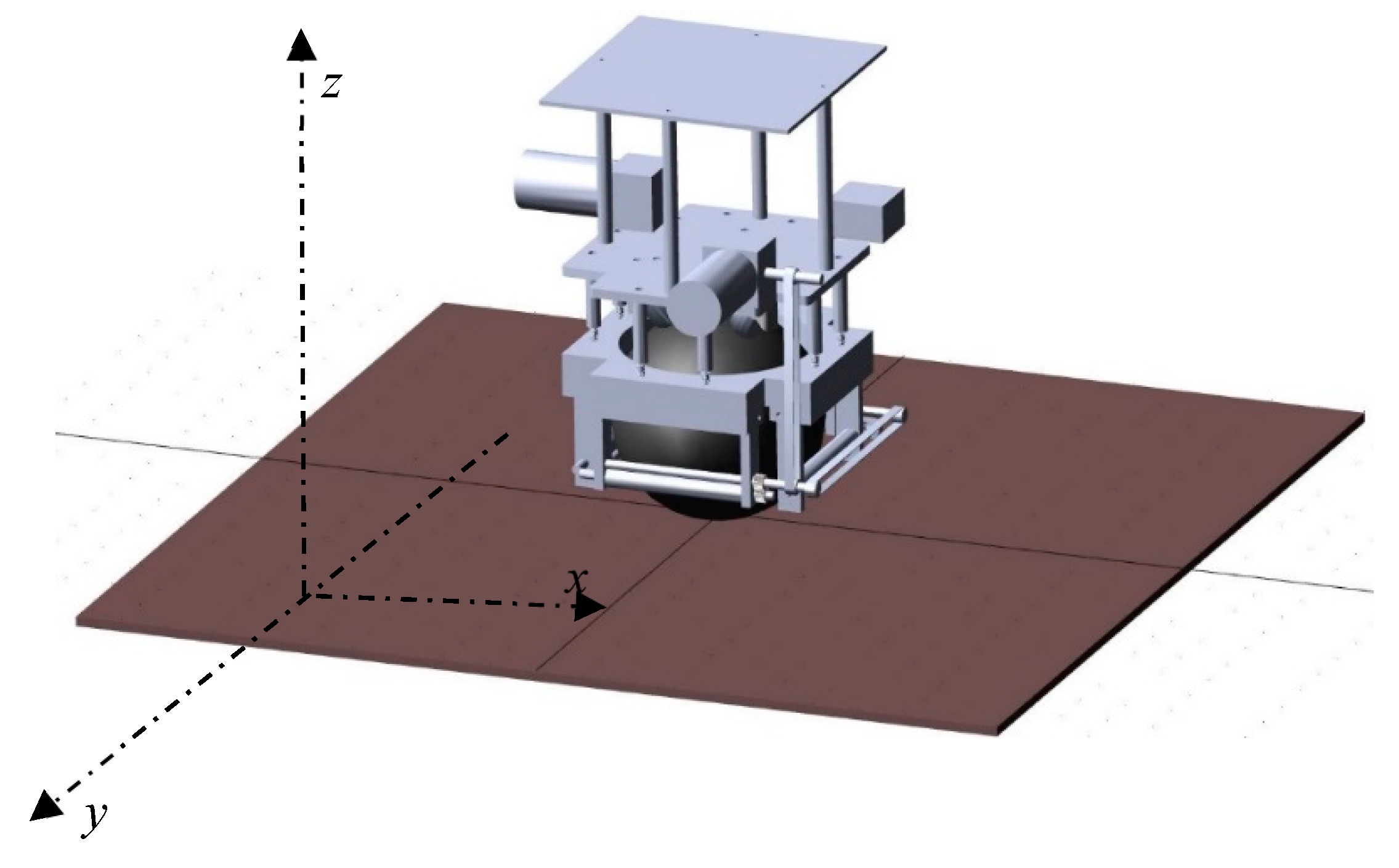
Figure 1 illustrates a BR system. In this study, the BR can be turned around the X and Y axes. According to
Figure 1, the system dynamics of a BR and an inverted pendulum are similar. In fact, the BR can be considered as an inverted pendulum that is supported by a single ball. This is undoubtedly a highly nonlinear control system. As mentioned above, two DC motors are placed on the two orthogonal axes. Thus, the movements for the X and Y axes can be independently controlled without coupling. It means that the controllers for the X-axis and Y-axis can be independently designed.
For simplification, the system model for any axis of the BR [
11] is represented as follows:
where
is the measurable system state vector,
is the dynamic function of the BR system,
denotes the system control gain where
for all
;
is system input and
is the perturbation and uncertainty.
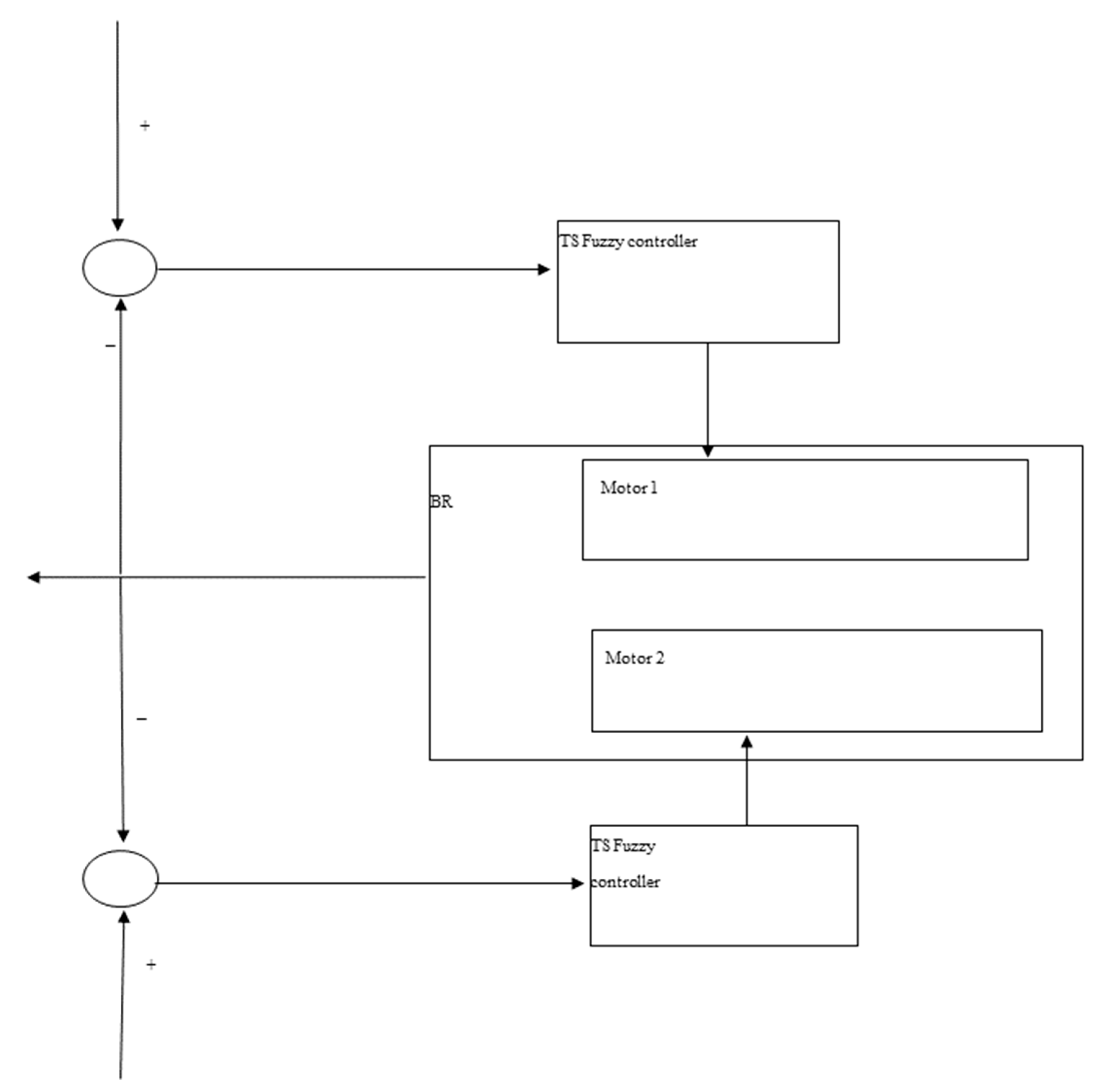
Figure 2 shows the proposed the dual TS fuzzy controller structure.
For implementation of fuzzy modeling, the system angle is limited within the range as . Then the fuzzy model of the BR is presented as follows:
Here the system matrices, and , are calculated based on Equation (1).
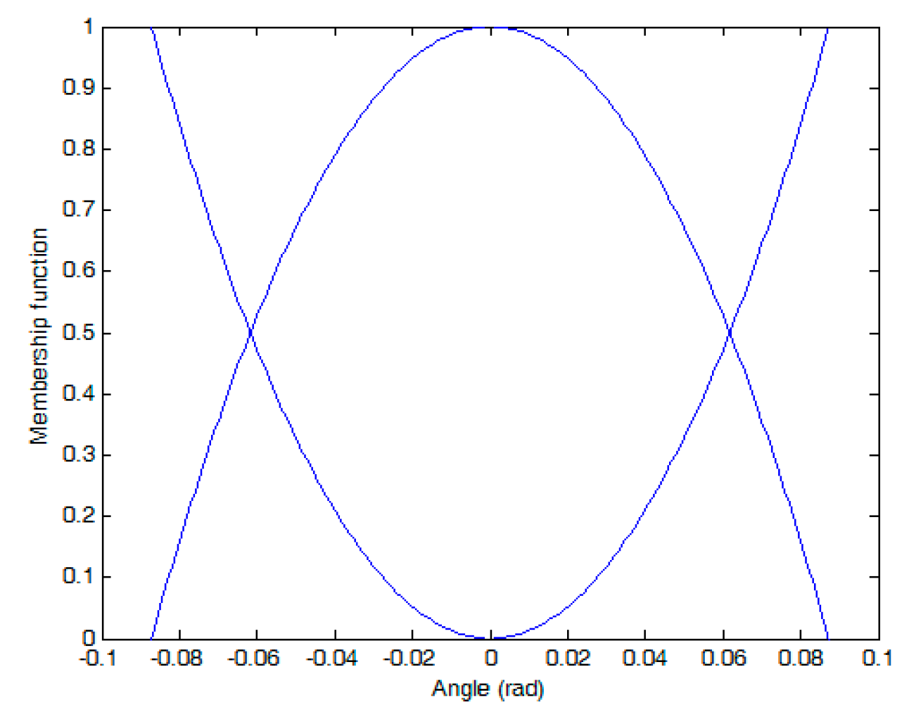
The membership functions of the BR of , , and , are composed of normalized Gaussian functions.
The membership functions are
where
.
, and
are shown in
Figure 3.
Then, the defuzzification of the abovementioned system model can derived as
In this study, the parallel distributed compensation (PDC) concept [
10] is used to design the model-based fuzzy controller. The fuzzy controller of the BR is presented as follows:
Controller rule i:
If
is
, then
where
and
are the local feedback gains. The whole system controller is presented as
Hence, each feedback gains in a consequential part that needs to be resolved.
By substituting Equation (7) into Equation (5), the closed-loop TS fuzzy model can be obtained as follows:
where
and
.
Next, the stability analysis of the closed-loop TS model for the overall BR can be derived as follows:
Lemma 1. [10] The fuzzy control system of Equation (8) is largely quadratically stable if there are symmetric matricesand, such that Equations (9)–(12) are satisfied. We defined the matrices,, andforandto meet the format of the MATLAB LMI toolbox and then applied them using the LMI method to obtain, , and.
3. Simulation Results
To verify the dual TS fuzzy control scheme, which can allow the BR to be able to balance and move stably, the system simulation test was carried out first.
Table 1 shows the parameters of the ball robot (BR) system.
According to [
11], the system matrix corresponding to 0 degrees and 5 degrees can be calculated. First, after substituting the system parameters into the fuzzy model, the system matrices at 0 degrees are as follows:
and
The system matrices at 5 degrees are as follows:
and
Then, the MATLAB LMI toolbox can be utilized to obtain
The next subsection shows the superior performance of the controller. In this section, the balance control at a fixed position and balance control with disturbances at the origin point are illustrated.
3.1. Balance Control
In this case, the balance control of the BR was tested first. Moreover, the robot position was also made to remain at the original point. Furthermore, to show the superior performance of the controller, the system initial states are
rad on the X-axis and
rad on the Y-axis, respectively. In other words, the BR starts at a slant situation.
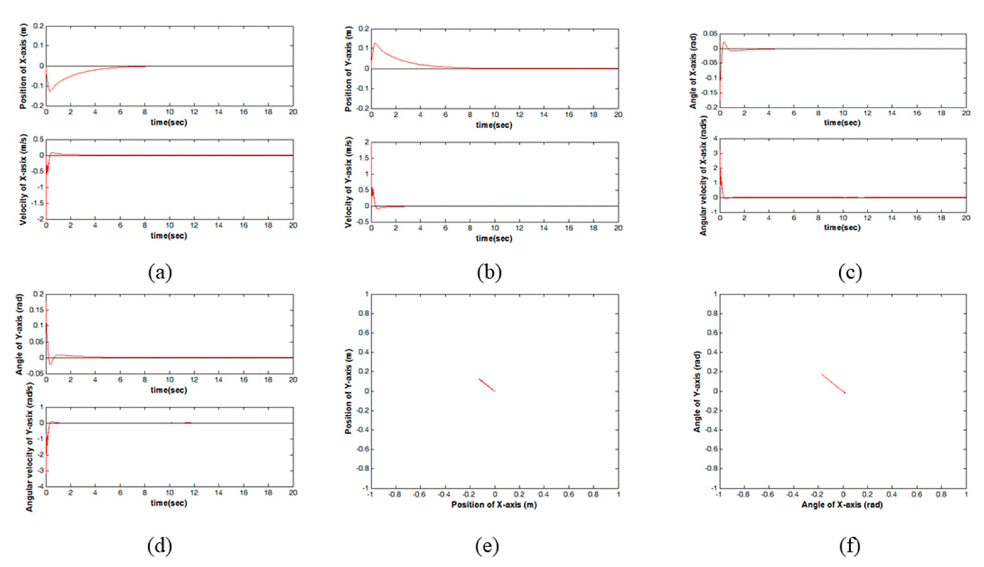
Figure 4 illustrates the system responses. The positional trajectory of the X-axis is shown in
Figure 4a.
Figure 4b is the positional trajectory of the Y-axis.
Figure 4c,d are the body angles of the X and Y axes, respectively.
Figure 4e,f are the movement of the BR on the X-Y plane and the angle of the BR on the X-Y plane, respectively. In
Figure 4c,d, the body angles of the BR are
rad on the X-axis and
rad on the Y-axis initially. This means the BR is in unstable states. However, according to the proposed controller, the body angles of the BR return to 0 degrees quickly at approximately 4 s. This means that the proposed TS fuzzy control can stably maintain the BR system at an unstable point. Moreover, in
Figure 4a,b, the robot leaves the original point in the beginning. The reason is that the BR needs to firstly maintain the body of the BR in a stable position. Then, the BR can also return to the given position at 8s. Thus, the BR can stand stably upright at the original point. In
Figure 4e, the BR stays at around the original point. In
Figure 4f, the angle of the BR is at around 0 degrees on the X-Y plane.
3.2. Balance Control with External Disturbance
In this test, the BR starts at the origin. This means that the BR starts at a stable situation. Then, at 10 s, an external disturbance is added to the system. In other words, an external disturbance is used to destroy the stability of the BR system. Moreover, the robot position is also made to remain at the original point.
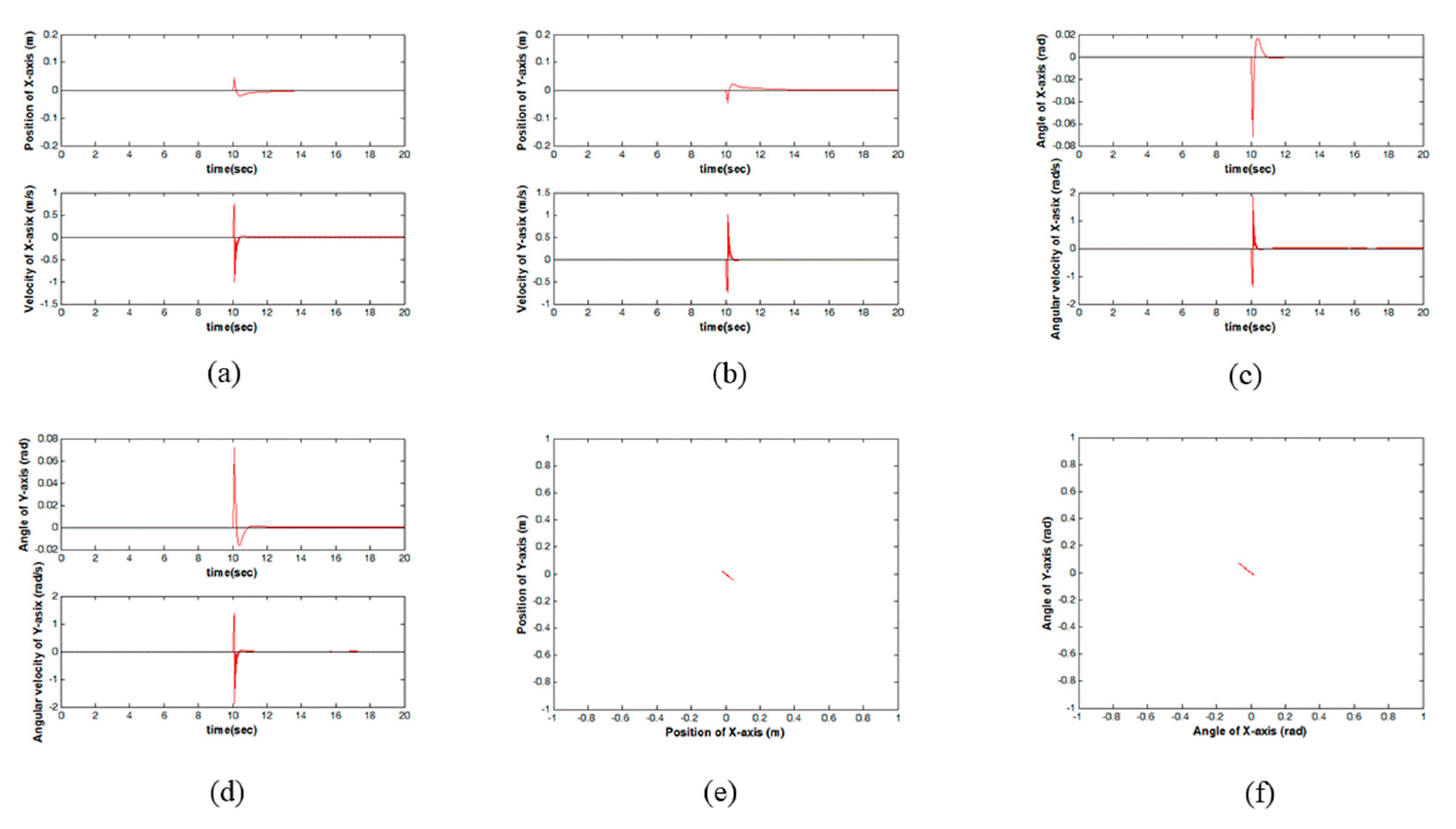
Figure 5 is the system performance.
Figure 5a,b are the movement of the BR on the X-axis and Y-axis, respectively.
Figure 5c,d are the body angles along the X and Y axes, respectively.
Figure 5e is the movement of the BR on the X-Y plane.
Figure 5f is the angle of the BR on the X-Y plane. In
Figure 5c,d, the body angles of the BR are all 0 degrees initially. Then, an external disturbance to destroy the stability of the BR is added to the system at 10 s. In
Figure 5c,d, the body angles of the BR return to 0 degrees quickly at approximately 11 s. Thus, the proposed TS fuzzy control can also stand stably when a system disturbance appears. Moreover, the BR leaves the original point at 10 s. Then, the BR can also return to the given position at 12 s. This means that the BR can also stay at the original point. Obviously, the proposed controller can deal with external disturbances well. In
Figure 5e, the BR stays at around the original point. In
Figure 5f, the angle of the BR is at around 0 degrees on the X-Y plane.
Superior system performance is achieved by the TS fuzzy controller, as reflected by the above simulation results. These results indicate that the controller is useful for BR control.
4. Experiment Results
In this section, the dual TS controller was used to implement the real-time control of the BR. The objective of the experiment was to keep the BR standing stably upright when it is moving.
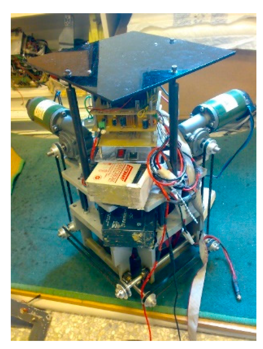
A personal computer and input/output board were used to obtain the measurement values in this study. Moreover, the personal computer was also used to give the system control signals. The hardware of the BR system can be divided into a machine platform and electronic circuit system. As mentioned above, the BR movement device is a bowling ball. The bowling ball is constructed by using two 24 V DC motors that are placed on two orthogonal axes. By using this structural restriction, the BR can be controlled without coupling. Therefore, there are two motors that transmit forces on the bowling ball. With this design, the BR can freely move over the full plane. The input/output board is the interface between the personal computer and the BR. The motor drivers are two H-bridge circuit systems. A pulse-width modulation square wave with a 10 kHz frequency is used to drive the motors. A sensor and a filter circuit serve as the bridge between the sensors. Then, the system analog states that are obtained from the BR are converted to digital signals by analog-to-digital converter circuits. The BR is approximately 40 cm high and 17 kg in weight. A photograph of the BR system is shown in
Figure 6.
The personal computer is the control center that receives the inputs of the system and calculates the control output. The input/output board in the personal computer has encoder interface circuits, programmable input/output, an analog-to-digital converter, and a digital-to-analog converter. Inclinometers, gyros, two incremental encoders and noise signals are used to obtain the system states. Filter circuits are used to filter the system noise signals and increase the precision of the feedback value. Finally, the “Borland C++ Builder” language is used to write the control algorithm. The system control interval is 1.5 ms.
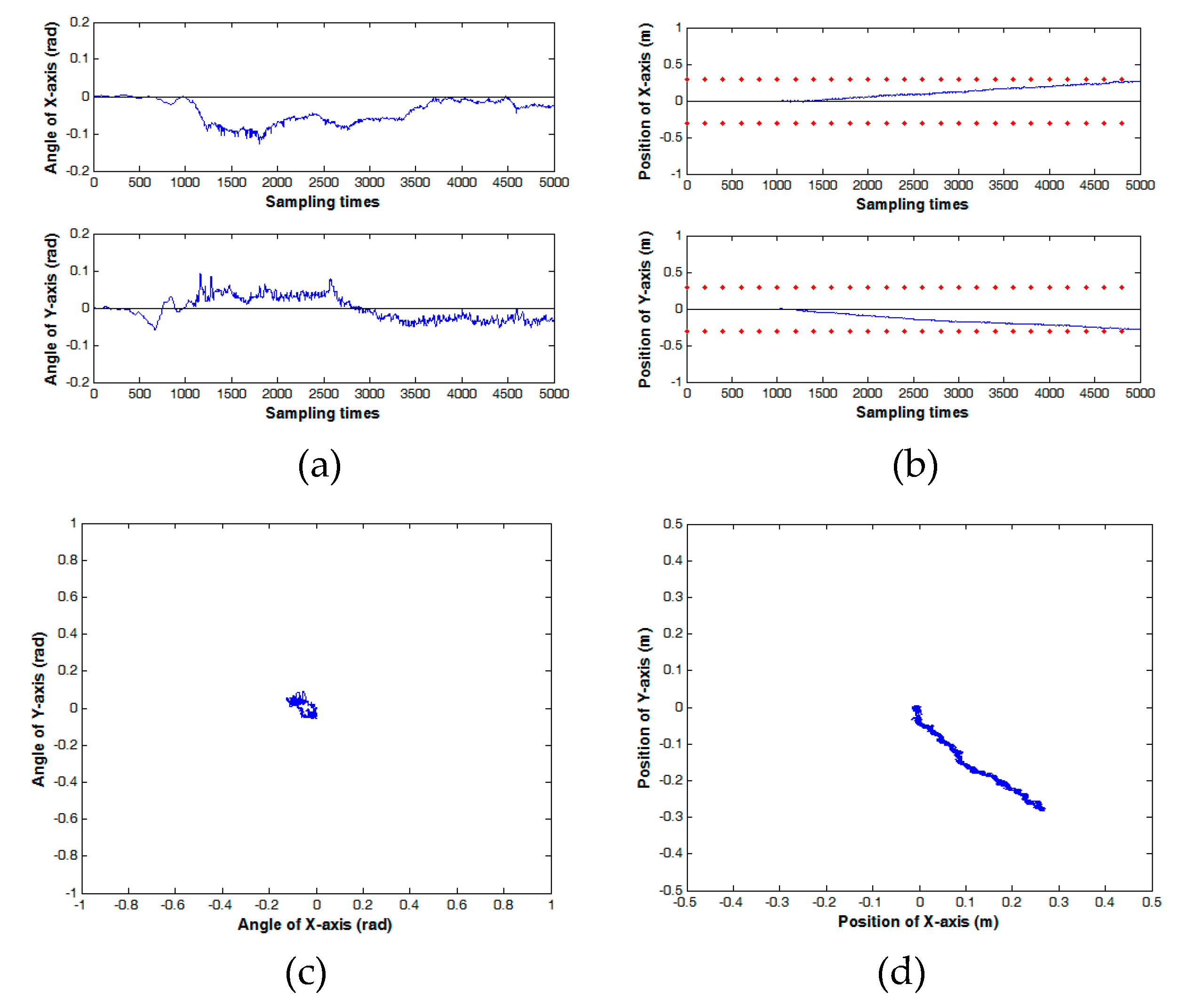
Figure 7 is the system responses with the initial states of
,
, and
. This means that the BR starts at the origin. Moreover, the target point of the x and y coordinates on the X-Y plane are 0.3 m and −0.3 m, respectively. In other words, the robot position is made to move to the fourth quadrant stably.
Figure 7a is the inclination angles for the X-axis and the Y-axis.
Figure 7b is the positions of the X-axis and the Y-axis. In
Figure 7a, the body angles of the BR are all 0 degrees initially. In
Figure 7b, the BR moves to the given position beginning at 1000 sampling times and touches the target position at approximately 5000 sampling times. In
Figure 7a, the angle of the X-axis departs from 0 degrees at approximately 1000 sampling times. When the BR arrives at the target position, then the angle of the X-axis gradually returns to 0 degrees. The same situation exists for the Y-axis. In
Figure 7c, the angle of the BR is around 0 degrees on the X-Y plane. In
Figure 7d, it shows that the BR moves to the fourth quadrant.
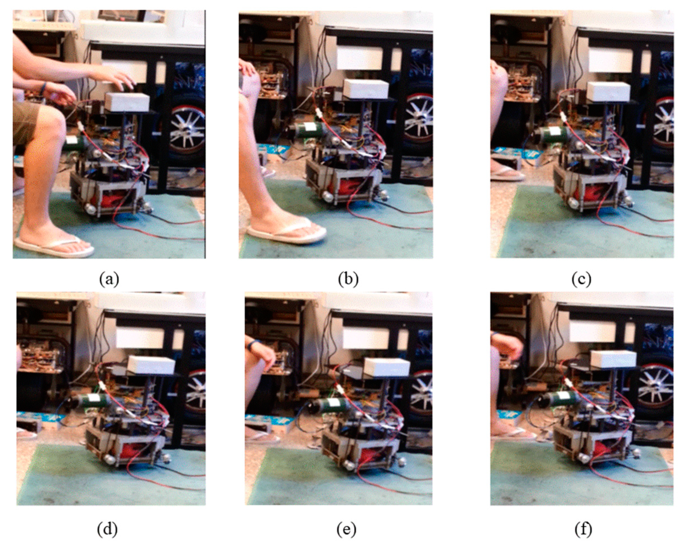
Figure 8 presents photographs of the sequence of the experiments. The BR starts at the origin in
Figure 8a. In other words, the BR starts at a stable situation. Then, the BR moves to balance itself in
Figure 8b,c. In
Figure 8d,e, it is obvious that the BR slants its body to move forward. In
Figure 8e, the BR stops at a given point.
The experimental results show that the controller provides satisfactory performance. Obviously, the proposed TS fuzzy controller is useful for the real world control of the BR.
5. Conclusions
This study has successfully designed a ball robot (BR) based on a novelty dual Takagi-Sugeno (TS) fuzzy control scheme. This proposed novelty controller combines two fuzzy control approaches for the BR system control. Moreover, in this study, the motors of the BR are mounted on two orthogonal axes. Then, the dual TS fuzzy controller can be independently implemented without coupling. In the proposed controller, the TS fuzzy model is adopted for fuzzy modeling of the BR. The conception of parallel distributed compensation (PDC) is utilized to develop a fuzzy control from the TS fuzzy models. The format of linear matrix inequalities (LMIs) can formulate sufficient conditions. In the end, the effectiveness of the proposed advanced control algorithm was verified by the experimental results and the results of two simulations. However, the proposed controller has achieved very good results. The fuzzy rules corresponding to 0 degrees and 5 degrees can also limit the system performance because the control range is too narrow. In our further work, the robustness of the proposed control scheme will be discussed. Moreover, the dual TS fuzzy control scheme can also be used for other real world applications.
Author Contributions
C.-H.C. contributions include conceptualization, investigation, project administration, software, validation, writing—original draft, and writing—review & editing. Y.-F.P. contributions include conceptualization, resources, and writing—review & editing.
Funding
This research received no external funding.
Acknowledgments
This work was supported by the Ministry of Science and Technology of Taiwan, R.O.C., under the Grant MOST 107-2221-E-019-048.
Conflicts of Interest
Here, we certify that this paper has not been published by another journal or conference record. Moreover, we certify that this paper is not currently under consideration by any other journal or conference publication. To the best of our knowledge, the named authors have no conflict of interest, financial or otherwise.
References
- Liang, Y.W.; Xu, S.D.; Liaw, D.C.; Chen, C.C. A study of T–S model-based SMC scheme with application to robot control. IEEE Trans. Ind. Electron. 2008, 55, 3964–3971. [Google Scholar] [CrossRef]
- Tanaka, K.; Iwasaki, M.; Wang, H.O. Switching control of an R/C hovercraft: Stabilization and smooth switching. IEEE Trans. Syst. Man. Cybern. B. Cybern. 2001, 31, 853–863. [Google Scholar] [CrossRef] [PubMed]
- Tanaka, K.; Ohtake, H.; Wang, H.O. A practical design approach to stabilization of a 3-DOF RC helicopter. IEEE Trans. Control Syst. Technol. 2004, 12, 315–325. [Google Scholar] [CrossRef]
- Begovich, O.; Sanchez, E.N.; Maldonado, M. Takagi-Sugeno fuzzy scheme for real-time trajectory tracking of an underactuated robot. IEEE Trans. Control Syst. Technol. 2002, 10, 14–20. [Google Scholar] [CrossRef]
- Xu, J.X.; Guo, Z.Q.; Lee, T.H. Design and implementation of a Takagi-Sugeno-Type fuzzy logic controller on a two-wheeled mobile robot. IEEE Trans. Ind. Electron. 2013, 60, 5717–5728. [Google Scholar] [CrossRef]
- Chiu, C.H.; Tsai, W.R. Design and implementation of an omnidirectional spherical mobile platform. IEEE Trans. Ind. Electron. 2015, 62, 1619–1628. [Google Scholar] [CrossRef]
- Huang, J.; Ri, S.; Liu, L.; Wang, Y.; Kim, J.; Pak, G. Nonlinear disturbance observer-based dynamic surface control of mobile wheeled inverted pendulum. IEEE Trans. Control Syst. Technol. 2015, 23, 2400–2407. [Google Scholar] [CrossRef]
- Liu, S.; Sun, D. Minimizing energy consumption of wheeled mobile robots via optimal motion planning. IEEE Trans. Mechatron. 2014, 19, 401–411. [Google Scholar] [CrossRef]
- Chiu, C.H. The design and implementation of a wheeled inverted pendulum using an adaptive output Recurrent cerebellar model articulation controller. IEEE Trans. Ind. Electron. 2010, 57, 1814–1822. [Google Scholar] [CrossRef]
- Huang, C.-H.; Wang, W.-J.; Chiu, C.-H. Design and implementation of fuzzy control on a two-wheel inverted pendulum. IEEE Trans. Ind. Electron. 2011, 58, 2988–3001. [Google Scholar] [CrossRef]
- Nagarajan, U.; Kantor, G.; Hollis, R. The ballbot: An omnidirectional balancing mobile robot. Int. J. Robot. Res. 2014, 33, 917–930. [Google Scholar] [CrossRef]
© 2019 by the authors. Licensee MDPI, Basel, Switzerland. This article is an open access article distributed under the terms and conditions of the Creative Commons Attribution (CC BY) license (http://creativecommons.org/licenses/by/4.0/).


