Continuous Pyrolysis Technology for Oily Sludge Treatment in the Chain-Slap Conveyors


Abstract
:1. Introduction
2. Material and Methods
2.1. Feedstock
2.2. Lab Scale Procedure
2.2.1. Fixed Bed Reactor
2.2.2. Experimental Procedure
2.3. Industrial-Scale Procedure
2.3.1. Continuous Pyrolysis Reactor
2.3.2. Industrial-Scale Procedure
3. Results
3.1. Lab-Scale Experimental Results
3.2. Feedstock
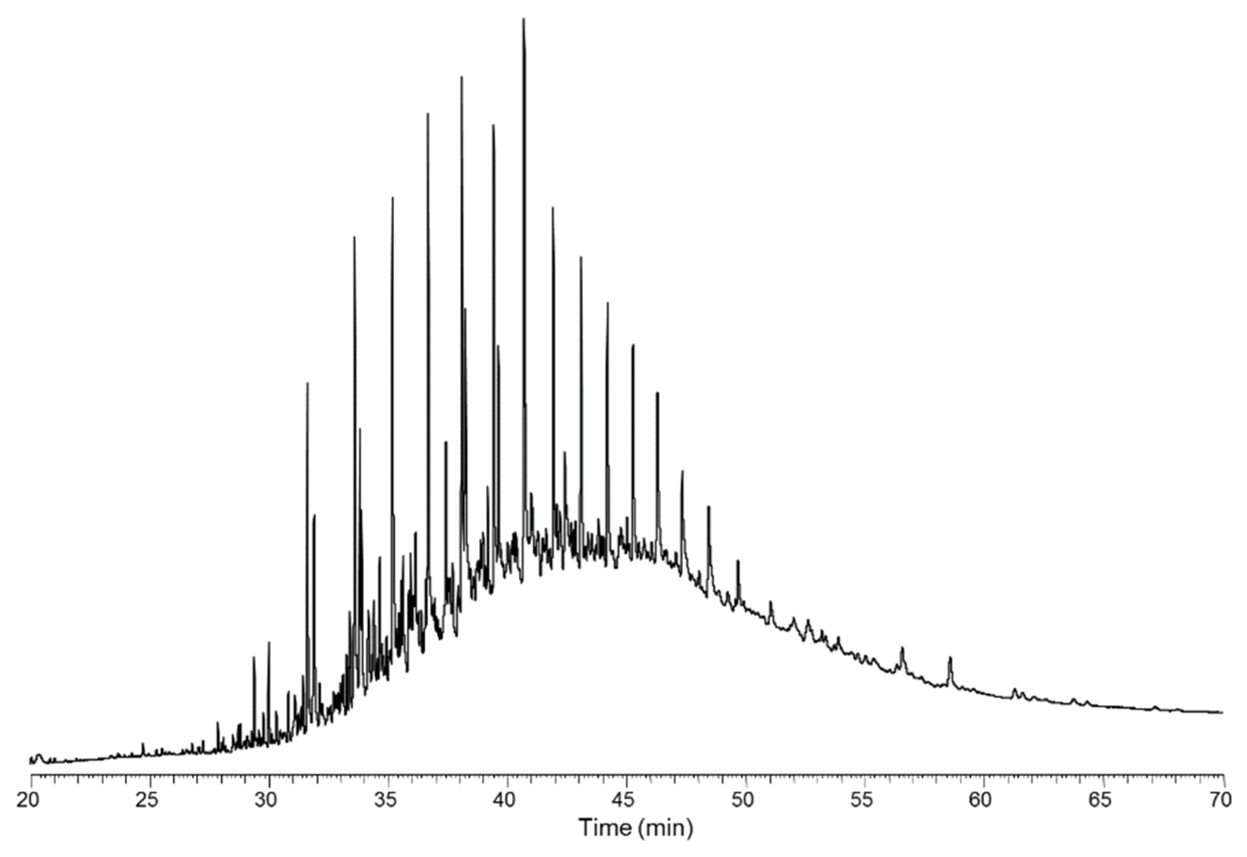
3.3. Pyrolysis Oil
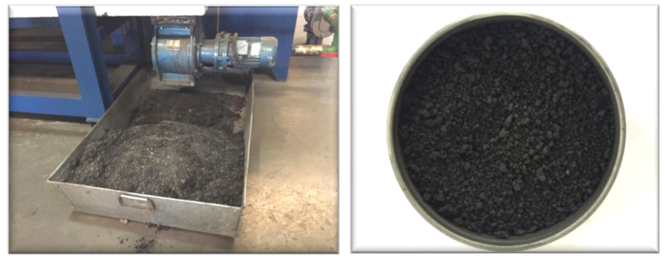
3.4. Pyrolysis Char
4. Conclusions
Author Contributions
Funding
Conflicts of Interest
References
- Yu, Q. Fundamental Study on Pyrolysis Characteristics of Oil Sludge; Shenyang Institute of Aeronautical Engineering: Shenyang, China, 2008. [Google Scholar]
- Chen, M.; Liu, Z.; Wang, X.; Xu, Z. New Technology and Development Direction of Harmless and Resource-based Treatment of Oily Sludge. Pet. Nat. Gas Chem. Ind. 2011, 40, 313–317. [Google Scholar]
- Pramf, P.; Vissanu, M.; Chatvalee, K.; Pramoch, R.; Thirasak, R.; Boonyarach, K. Pyrolysis of APl separator sludge. J. Anal. Appl. Pyrolysis 2003, 68–69, 547–560. [Google Scholar]
- Chen, Z.; Wei, L. Research of Oily Sludge Treatment Technology and Technological Application; The Science Publishing Company: Beijing, China, 2012. [Google Scholar]
- Cypres, R.; Bettens, B. Production of benzoles and active car-bon from waste rubber and plastic materials by means of py-rolysis with simultaneous post-cracking. In Pyrolysis and Gasification C; Elsevier Science Publ. Co. Inc.: London, UK, 1989; pp. 209–216. [Google Scholar]
- Karminsky, W.; Sinn, H. Pyrolysis of Plastic Waste and Scrap Tires Using a Fluidized Bed Process; American Chemical Society: Washington, DC, USA, 1980; pp. 68–77. [Google Scholar]
- Black, J.W.; Brown, D.B. CAR Technology; Castle Capital Inc.: Clarence, NY, USA, 1991; Volume 55, pp. 203–210. [Google Scholar]
- Chen, C.; Li, S.; Yue, C.; Kruttschnitt, T.; Pruckner, E.; Yao, Q. Rotary Continuous Pyrolysis of Oily Sludge-Mass-Energy Balance and Product Analysis. J. Chem. Eng. 2006, 03, 650–657. [Google Scholar]
- Janetta, R. Plasma Waste Management chemical gasification of sewage sludge. Waste Manag. Res. 2003, 21, 3841. [Google Scholar]
- Ayen, R.; Swansrom, C.P. Low temperature thermal treatment of petroleum refinery waste sludges. Environ. Process 1992, 11, 127–132. [Google Scholar] [CrossRef]
- Pandey, D.S.; Katsaros, G.; Lindfors, C.; Leahy, J.J.; Tassou, S.A. Fast Pyrolysis of Poultry Litter in a Bubbling Fluidised Bed Reactor: Energy and Nutrient Recovery. Sustainability 2019, 11, 2533. [Google Scholar] [CrossRef]
- Sarfraz, R.; Li, S.; Yang, W.; Zhou, B.; Xing, S. Assessment of Physicochemical and Nutritional Characteristics of Waste Mushroom Substrate Biochar under Various Pyrolysis Temperatures and Times. Sustainability 2019, 11, 277. [Google Scholar] [CrossRef]
- Akyürek, Z. Sustainable Valorization of Animal Manure and Recycled Polyester: Co-pyrolysis Synergy. Sustainability 2019, 11, 2280. [Google Scholar] [CrossRef]
- Oliveira Neto, G.C.; Chaves, L.E.C.; Pinto, L.F.R.; Santana, J.C.C.; Amorim, M.P.C.; Rodrigues, M.J.F. Economic, Environmental and Social Benefits of Adoption of Pyrolysis Process of Tires: A Feasible and Ecofriendly Mode to Reduce the Impacts of Scrap Tires in Brazil. Sustainability 2019, 11, 2076. [Google Scholar] [CrossRef]
- Zhang, M. Determination of total sulfur in oily sludge and migration of sulfur during pyrolysis. In Proceedings of the 2014 Annual Meeting of the Chinese Society of Environmental Sciences, Chengdu, China, 22–23 October 2014; Volume 3. [Google Scholar]
- Liu, D.; Li, Y.; Wang, M.; Wang, L. Characteristic of biomass carbon from corn straw pyrolysis at low temperature. Power Grid Clean Energy 2017, 33, 105–109. [Google Scholar]
- Tomasi Morgano, M.; Leibold, H.; Richter, F.; Dieter, S.; Helmut, S. Screw pyrolysis technology for sewage sludge treatment. Waste Manag. 2018, 73, 487–495. [Google Scholar] [CrossRef] [PubMed]
- Tang, C.; Guan, J.; Zhang, M.; Ma, C. Development and Adsorption Characteristics of Adsorbents for Oily Sludge. Pet. Refin. Chem. Ind. 2016, 47, 22–26. [Google Scholar]
- Tang, H. Experimental Study on Thermal Treatment of Oily Sludge; Zhejiang University: Hangzhou, China, 2008. [Google Scholar]


| Reaction Temperature | 450 °C | 500 °C | 550 °C | 600 °C |
|---|---|---|---|---|
| Oil Phase (%) | 16.7 | 17.1 | 15.9 | 14.6 |
| Water Phase (%) | 61.7 | 61.9 | 62.8 | 64.4 |
| Permanent Gas (%) | 4.2 | 5.2 | 9.1 | 8.5 |
| Char (%) | 17.4 | 17.1 | 15.8 | 15.7 |
| Ultimate Analysis wt.%(d.b.) | ||||
|---|---|---|---|---|
| C | H | O | N | S |
| 54.86 | 5.80 | 10.18 | 2.13 | 1.5 |
| Proximate analysis wt.% (a.r.) | Heating value (kcal/kg) (a.r.) | |||
| Moisture | Ash | Volatile Matter | Fixed Carbon | LHV |
| 62.67 | 8.59 | 21.51 | 7.23 | 2220 |
| Ultimate analysis wt.%(d.b.) | ||||
|---|---|---|---|---|
| C | H | O | N | S |
| 85.5 | 11.58 | 1.09 | 0.85 | 0.98 |
| Components Analysis | Heating value (kcal/kg) (a.r.) | |||
| C7–C9 | C10–C15 | C16–C18 | C19 or above | LHV |
| 12.2 | 60.1 | 8.2 | 19.4 | 9682 |
| Ultimate analysis wt.%(d.b.) | ||||
|---|---|---|---|---|
| C | H | O | N | S |
| 43.65 | 1.46 | 0.49 | 1.27 | 2.58 |
| Proximate analysis wt.% (a.r.) | Heating value (kcal/kg) (a.r.) | |||
| Moisture | Ash | Volatile Matter | Fixed Carbon | LHV |
| 2.16 | 52.71 | 21.51 | 36.98 | 3690 |
| As | Cd | Pb | Ni | Cr | Zn | Cu | |
|---|---|---|---|---|---|---|---|
| Content (mg/kg) | 160.50 | 3.22 | 623.9 | 764.7 | 233.3 | 10867.7 | 266.70 |
| Maximum permissible content (mg/kg) | |||||||
| In acidic soils (PH < 6.5) | 75 | 5 | 300 | 100 | 600 | 500 | 250 |
| In alkaline soils (PH > 6.5) | 75 | 20 | 1000 | 200 | 1000 | 1000 | 500 |
© 2019 by the authors. Licensee MDPI, Basel, Switzerland. This article is an open access article distributed under the terms and conditions of the Creative Commons Attribution (CC BY) license (http://creativecommons.org/licenses/by/4.0/).
Share and Cite
Tang, X.; Wei, X.; Chen, S. Continuous Pyrolysis Technology for Oily Sludge Treatment in the Chain-Slap Conveyors. Sustainability 2019, 11, 3614. https://doi.org/10.3390/su11133614
Tang X, Wei X, Chen S. Continuous Pyrolysis Technology for Oily Sludge Treatment in the Chain-Slap Conveyors. Sustainability. 2019; 11(13):3614. https://doi.org/10.3390/su11133614
Chicago/Turabian StyleTang, Xinxin, Xuesong Wei, and Songying Chen. 2019. "Continuous Pyrolysis Technology for Oily Sludge Treatment in the Chain-Slap Conveyors" Sustainability 11, no. 13: 3614. https://doi.org/10.3390/su11133614
APA StyleTang, X., Wei, X., & Chen, S. (2019). Continuous Pyrolysis Technology for Oily Sludge Treatment in the Chain-Slap Conveyors. Sustainability, 11(13), 3614. https://doi.org/10.3390/su11133614