Durability Studies of Solar Reflectors Used in Concentrating Solar Thermal Technologies under Corrosive Sulfurous Atmospheres


 ,
, 
Abstract
1. Introduction
2. Materials and Methods
2.1. Experimental Approach
2.2. Description of Materials
2.3. Experimental Campaign
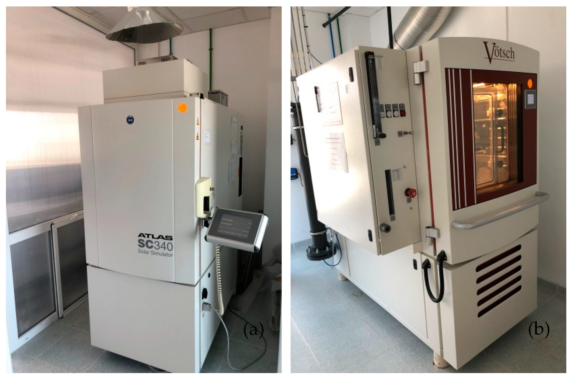
2.4. Description of Instruments
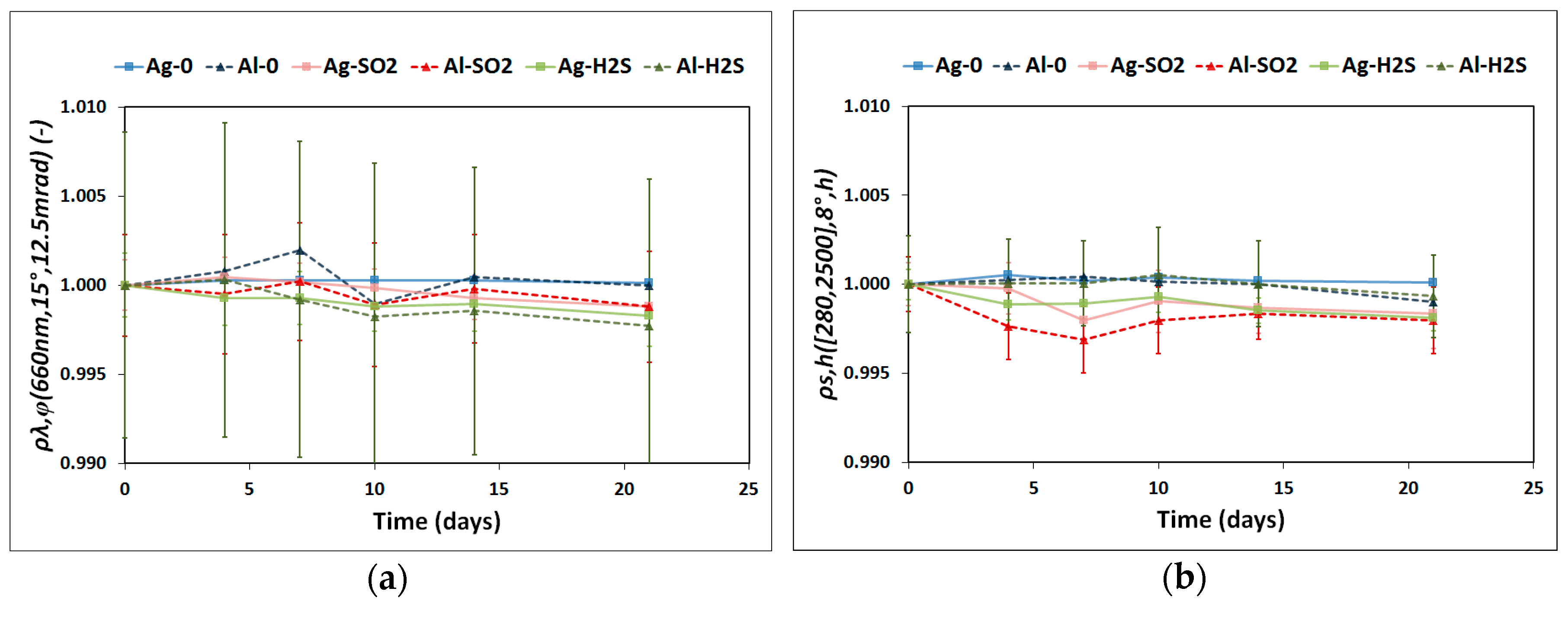
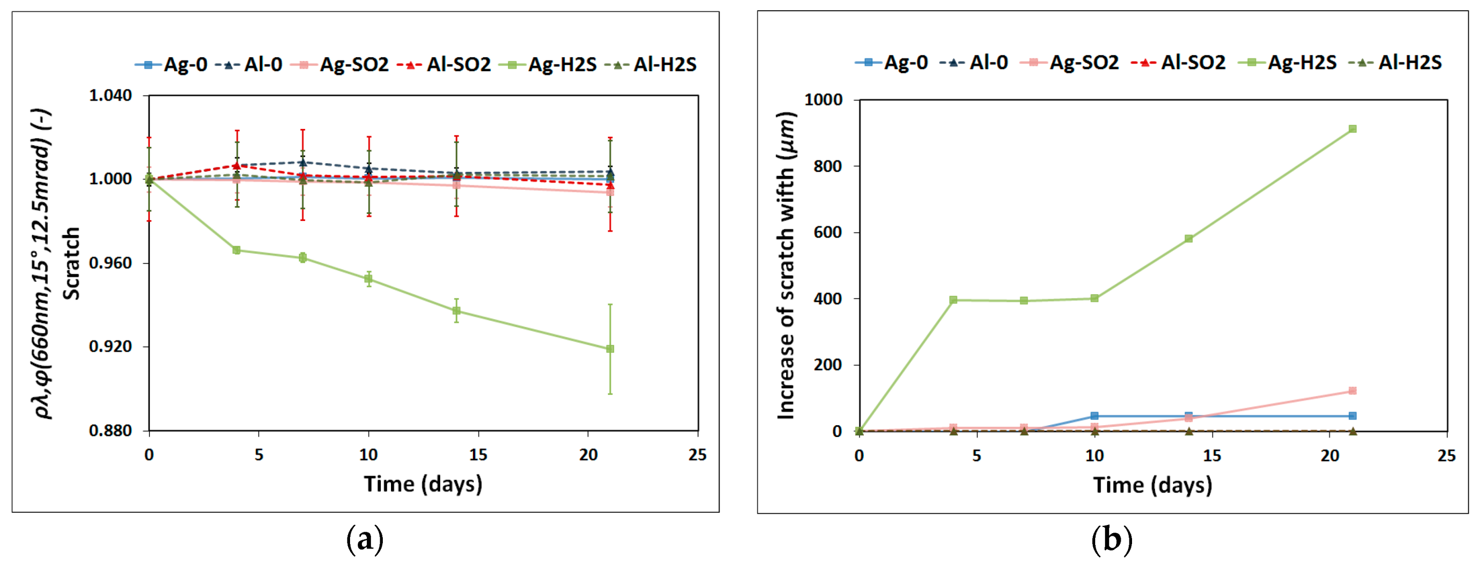
- A portable reflectometer model 15R-USB manufactured by Devices and Services [33] was used to calculate the monochromatic specular reflectance, ρλ,φ, in a wavelength range of 635–685 nm with a peak at 660 nm, ρλ,φ (660 nm, 15°, 12.5 mrad). An acceptance angle of 12.5 mrad was used to measure nine different areas of the reflector sample, as illustrated in Figure 2. This image shows that the scratch is exactly on the square A8. Hence, ρλ,φ is expected to be lower in this pre-damaged area than in the rest of the sample and therefore was treated independently. Three measurements on the square A8 were taken to provide statistics on the results. The remaining eight areas were considered consistent and as a result their reflectance average represents the reflectance value of the undamaged surface.
- Solar-weighted hemispherical reflectance, ρs,h, was measured with a spectrophotometer model Lambda 1050 with a 150 mm diameter integrating-sphere accessory manufactured by Perkin Elmer [34]. The wavelength range measured was 280–2500 nm with an incidence angle of 8°, ρs,h ([280, 2500] nm, 8°, h). This parameter was calculated according to the ISO Standard 9050 formulation [35] using the solar direct radiation spectrum from ASTM G173-03 [36]. The samples were measured at the central position (A5 zone in Figure 2) by rotating them three times to check for any possible anisotropy.
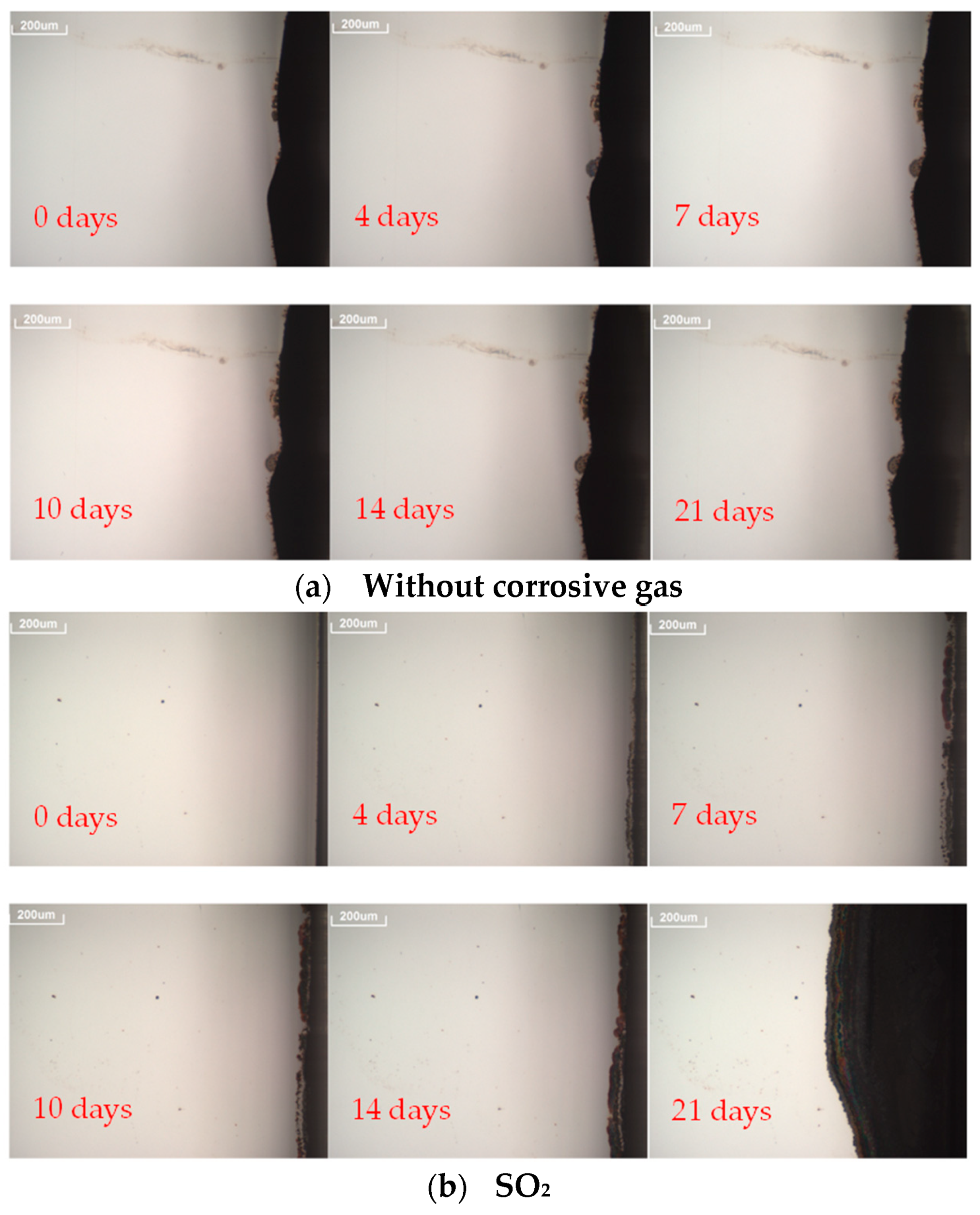
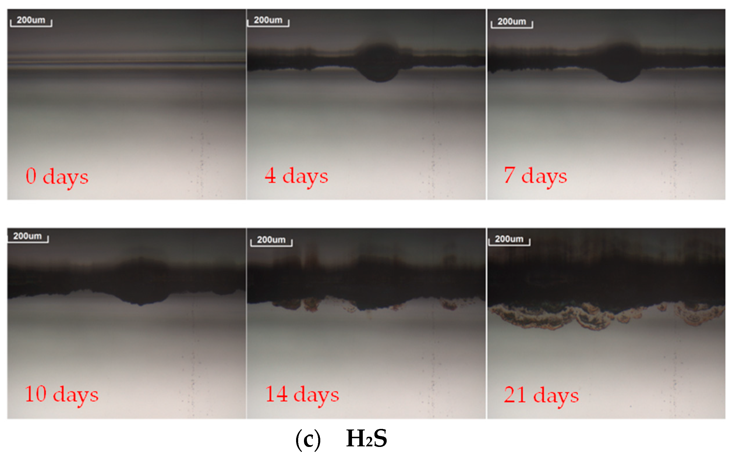
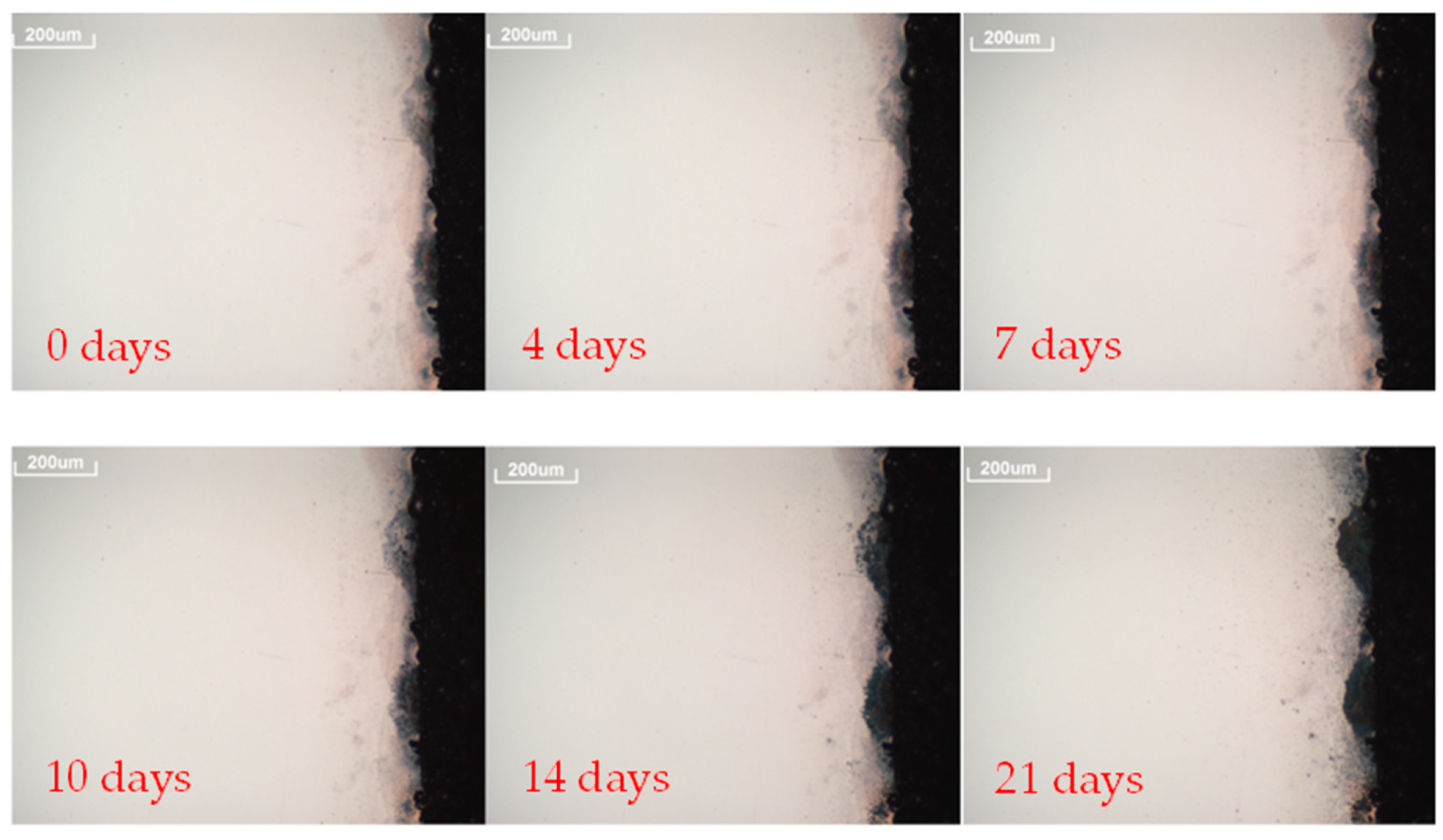
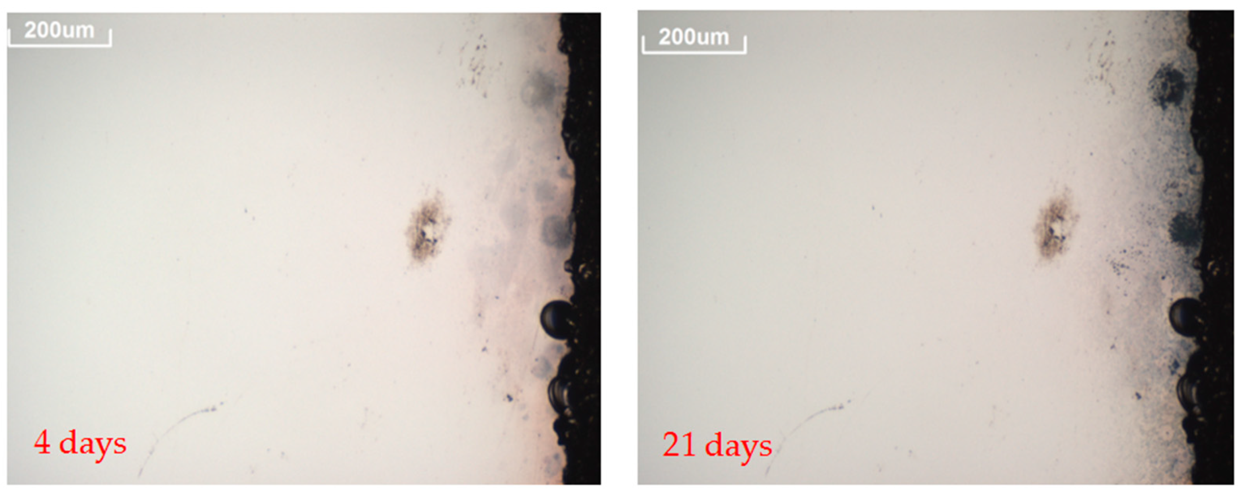
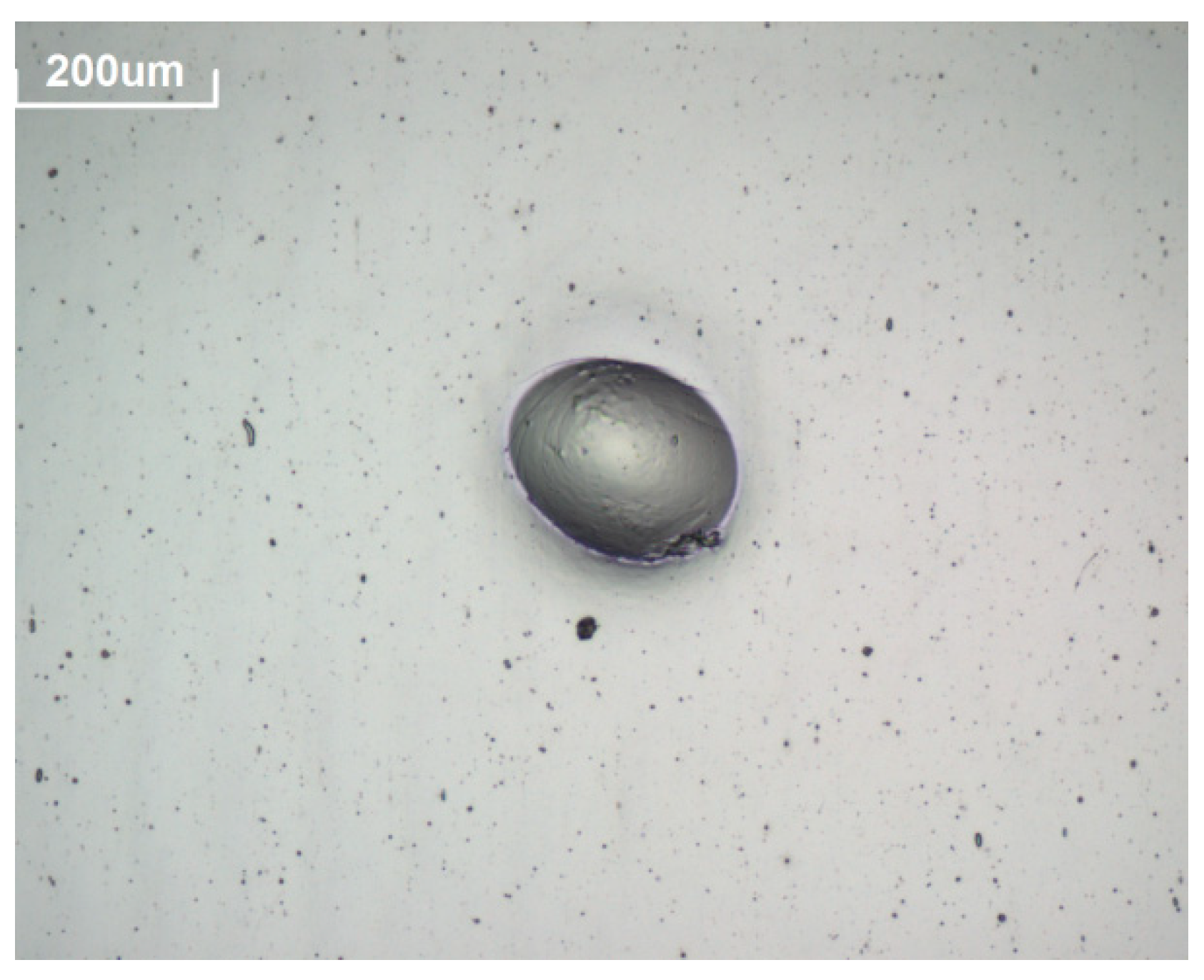
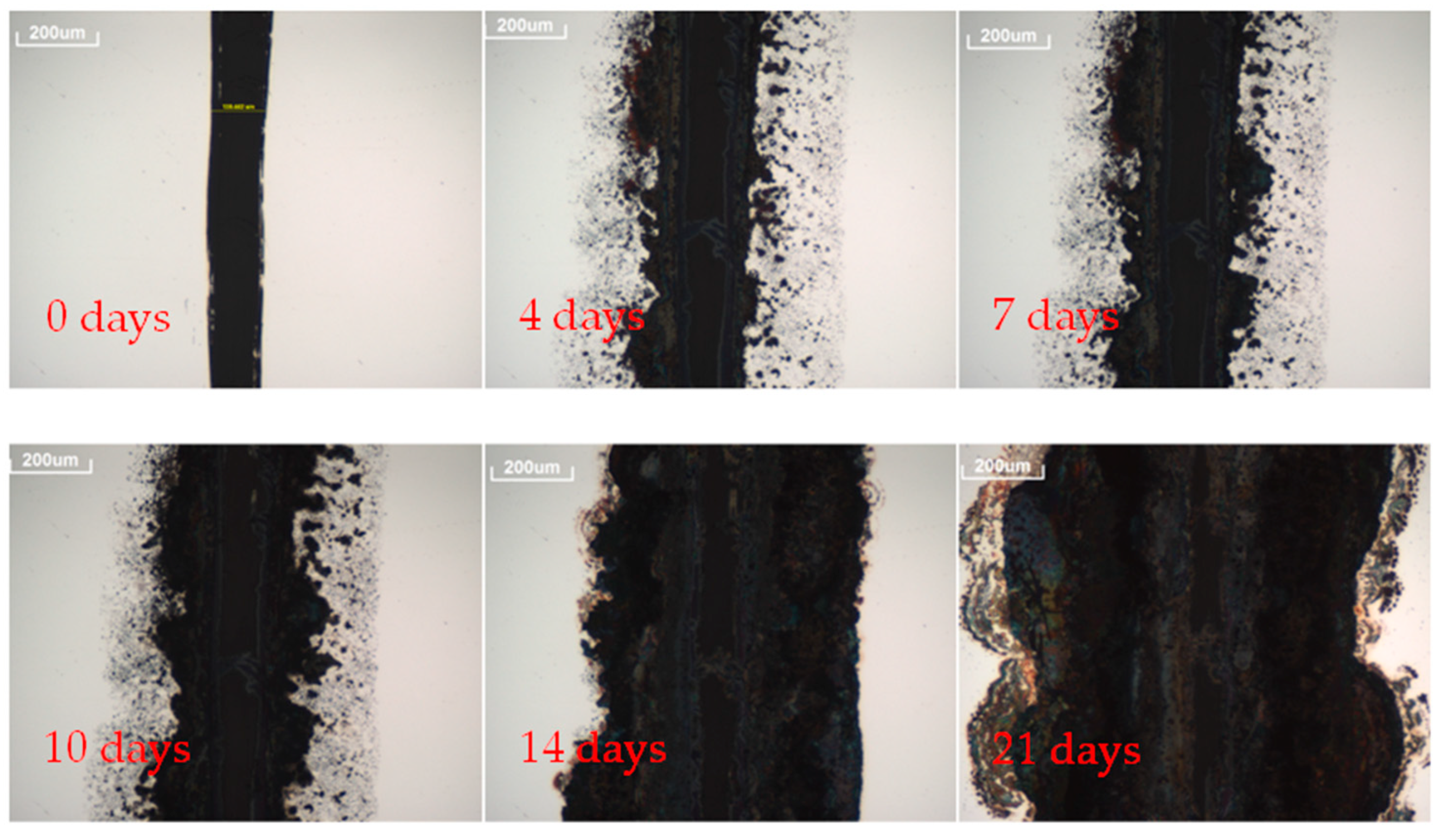
- A 3D OM model Axio CSM 700 manufactured by Zeiss was used to follow the evolution of prospective defects [37]. Pictures of the defects, such as spots or edge corrosion, were taken at 10× magnification to assess the corrosion originated in the reflector layer. Pictures of the reflectors surfaces were taken every time the analysis was carried out.
3. Results
4. Conclusions
Author Contributions
Funding
Acknowledgments
Conflicts of Interest
References
- Protermosolar. Available online: www.protermosolar.es (accessed on 7 June 2018).
- IEA. Technology Roadmap: Solar Thermal Electricity. 2014. Available online: https://webstore.iea.org/technology-roadmap-solar-thermal-electricity-2014 (accessed on 7 June 2018).
- Fernández-García, A.; Rojas, E.; Pérez, M.; Silva, R.; Hernández-Escobedo, Q.; Manzano-Agugliaro, F. A parabolic-trough collector for cleaner industrial process heat. J. Clean. Prod. 2015, 89, 272–285. [Google Scholar] [CrossRef]
- García-Segura, A.; Fernández-García, A.; Ariza, M.J.; Valenzuela, L.; Sutter, F. Durability studies of solar reflectors: A review. Renew. Sustain. Energy Rev. 2016, 62, 453–467. [Google Scholar] [CrossRef]
- Rice, D.W.; Cappell, R.J.; Kinsolving, W.; Laskowski, J.J. Indoor corrosion of metals. J. Electrochem. Soc. 1980, 127, 891–901. [Google Scholar] [CrossRef]
- Chudnovsky, B.H. Degradation of power contacts in industrial atmosphere: Silver corrosion and whiskers. In Proceedings of the Forty-Eighth IEEE Holm Conference on Electrical Contacts, Orlando, FL, USA, 23 October 2002; pp. 1–22. [Google Scholar] [CrossRef]
- Franey, J.P.; Kammlott, G.W.; Graedel, T.E. The corrosion of silver by atmospheric sulfurous gases. Corros. Sci. 1985, 25, 133–143. [Google Scholar] [CrossRef]
- Watanabe, M.; Hokazono, A.; Handa, T.; Ichino, T.; Kuwaki, N. Corrosion of copper and silver plates by volcanic gases. Corros. Sci. 2006, 48, 3759–3766. [Google Scholar] [CrossRef]
- Leygraf, C.; Graedel, T.E. Atmospheric Corrosion; Wiley Interscience: Hoboken, NJ, USA, 2000. [Google Scholar]
- Hillman, C.; Arnold, J.; Binfield, S.; Seppi, J. Silver and sulfur: Case studies, physics, and possible solutionst. In SMTA International Conference Proceedings; DfR Solutions: College Park, MD, USA, 10 September 2007. [Google Scholar]
- Sarver, T.; Al-Qaraghuli, A.; Kazmerski, L. A comprehensive review of the impact of dust on the use of solar energy: History, investigations, results, literature, and mitigation approaches. Renew. Sustain. Energy Rev. 2016, 22, 698–733. [Google Scholar] [CrossRef]
- Karim, M.; Naamane, S.; Delord, C.; Bennouna, A. Laboratory simulation of the surface erosion of solar glass mirrors. Sol. Energy 2015, 118, 520–532. [Google Scholar] [CrossRef]
- Sansom, C.L.; Comley, P.; King, P.; Almond, H.J.; Atkinson, C.; Endaya, E. Predicting the effects of sand erosion on collector surfaces in CSP plants. Energy Procedia 2015, 69, 198–207. [Google Scholar] [CrossRef]
- Wiesinger, F.; Sutter, F.; Fernández-García, A.; Reinhold, J.; Pitz-Paal, R. Sand erosion on solar reflectors: Accelerated simulation and comparison with field data. Sol. Energy Mater. Sol. Cells 2016, 145, 303–313. [Google Scholar] [CrossRef]
- Sutter, F.; Fernández-García, A.; Heller, P.; Anderson, K.; Wilson, G.; Schmücker, M.; Marvig, P. Durability testing of silvered-glass mirrors. Energy Procedia 2015, 69, 1568–1577. [Google Scholar] [CrossRef]
- Slamova, K.; Duerr, I.; Kaltenbach, T.; Koehl, M. Degradation effects of maritime atmosphere on metallic components of solar collectors. Sol. Energy Mater. Sol. Cells 2016, 147, 246–254. [Google Scholar] [CrossRef]
- Morcillo, M.; Chico, B.; De La Fuente, D.; Simancas, J. Looking back on contributions in the field of atmospheric corrosion offered by the MICAT ibero-american testing network. Int. J. Corros. 2012, 2012. [Google Scholar] [CrossRef]
- Wette, J.; Sutter, F.; Fernández-García, A.; Ziegler, S.; Dasbach, R. Comparison of degradation on aluminum reflectors for solar collectors due to outdoor exposure and accelerated aging. Energies 2016, 9, 916. [Google Scholar] [CrossRef]
- DiGrazia, M.J.; Gee, R.; Jorgensen, G.J.; Bingham, C. Service life prediction for ReflecTech® mirror film. In Proceedings of the WREF 2012 Conference Proceedings, World Renewable Energy Forum, Denver, CO, USA, 13–17 May 2012. [Google Scholar]
- Sutter, F.; Ziegler, S.; Schmücker, M.; Heller, P.; Pitz-Paal, R. Modelling of optical durability of enhanced aluminum solar reflectors. Sol. Energy Mater. Sol. Cells 2012, 107, 37–45. [Google Scholar] [CrossRef]
- Coyle, R.T.; Barrett, J.M.; Call, P.J. Durability of silver-glass mirrors in moist acid vapors. Sol. Energy Mater. 1982, 6, 351–373. [Google Scholar] [CrossRef]
- Almanza, R.; Jiefeng, C.; Correa, G.; Mazari, M. Further option for solar concentrators: Aluminum first surface mirrors. Sol. Energy 1995, 54, 333–343. [Google Scholar] [CrossRef]
- García-Segura, A.; Fernández-García, A.; Ariza, M.J.; Sutter, F.; Valenzuela, L. Effects of reduced sulphur atmospheres on reflector materials for concentrating solar thermal applications. Corros. Sci. 2018, 133, 78–93. [Google Scholar] [CrossRef]
- Fernández-García, A.; Díaz-Franco, R.; Martínez-Arcos, L.; Wette, J. Study of the effect of acid atmospheres in solar reflectors durability under accelerated aging conditions. Energy Procedia 2014, 49, 1682–1691. [Google Scholar] [CrossRef]
- García-Segura, A.; Fernández-García, A.; Ariza, M.J.; Sutter, F.; Valenzuela, L. Degradation of concentrating solar thermal reflectors in acid rain atmospheres. Sol. Energy Mater. Sol. Cells 2018, 186, 92–104. [Google Scholar] [CrossRef]
- Abbott, W. Effects of industrial air pollutants on electrical contact materials. IEEE Trans. Parts Hybrids Packag. 1974, 10, 24–27. [Google Scholar] [CrossRef]
- Steppan, J.J.; Roth, J.A.; Hall, L.C.; Jeannotte, D.A.; Carbone, S.P. A review of corrosion failure mechanisms during accelerated tests. J. Electrochem. Soc. 1987, 134, 175–189. [Google Scholar] [CrossRef]
- Graedel, T.E. Corrosion mechanisms for aluminum exposed to the atmosphere. J. Electrochem. Soc. 1989, 136, 204C–212C. [Google Scholar] [CrossRef]
- Graedel, T.E. Corrosion mechanisms for silver exposed to the atmosphere. J. Electrochem. Soc. 1992, 39, 1963–1970. [Google Scholar] [CrossRef]
- Scratching Tool acc. to van Laar, Model 426. ERICHSEN GmbH & Co. KG. Available online: https://www.erichsen.de/corrosion-testing/specimen-preparation/scratching-tool-acc-to-van-laar-model-426/technical-description-model-426-pdf/download (accessed on 24 July 2018).
- Sansom, C.; Fernández-García, A.; Sutter, F.; Almond, H.; King, P.; Martínez-Arcos, L. Soiling and cleaning of polymer film solar reflectors. Energies 2016, 9, 1006. [Google Scholar] [CrossRef]
- IEC 60068-2-43:2003. Environmental Testing—Part 2-43: Tests—Test Kd: Hydrogen Sulphide Test for Contacts and Connections. Available online: https://webstore.iec.ch/publication/526 (accessed on 24 July 2018).
- Devices and Services (D&S). Devices and Services Portable Specular Reflectometer Model 15R-USB Operation and Maintenance Manual; Devices and Services (D&S): Dallas, TX, USA, 2009. [Google Scholar]
- Perkin Elmer. Perkin Elmer High Performance Lambda Spectrophotometers Hardware Guide. Available online: http://www.perkinelmer.com/product/lambda-950-uv-vis-nir-spectrophotometer-l950 (accessed on 24 July 2018).
- International Organization for Standardization. ISO 9050, Glass in Building, Determination of Light Transmittance, Solar Direct Transmittance, Total Solar Energy Transmittance, Ultraviolet Transmittance and Related Glazing Factors, Geneva. 2003. Available online: https://www.iso.org/standard/35062.html (accessed on 24 July 2018).
- American Society for Testing and Materials (ASTM). ASTM Standard G173-03, Terrestrial Reference Spectra for Photovoltaic Performance Evaluation; American Society for Testing and Materials (ASTM): West Conshohocken, PA, USA, 2003. [Google Scholar]
- Carl Zeiss MicroImaging GmbH. Zeiss 3D Light Microscope Model Axio CSM 700 Operating Manual. 2010. Available online: https://www.rdmag.com/product-release/2010/01/axio-csm-700-confocal-light-microscope (accessed on 24 July 2018).
- Brogren, M.; Karlsson, B.; Roos, A.; Werner, A. Analysis of the effects of outdoor and accelerated ageing on the optical properties of reflector materials for solar energy applications. Sol. Energy Mater. Sol. Cells 2004, 82, 491–515. [Google Scholar] [CrossRef]


| Pollutant | Clean Room | Controlled Environment | Rural /Urban | Heavy Urban or Industries | Adjacent to Industries | Inside Industries |
|---|---|---|---|---|---|---|
| H2S | 0.001 | 0.004 | 0.004 | 0.2 | 4.1 | 28.5 |
| SO2 | 0.038 | 0.038 | 0.038 | 0.4 | 3.8 | 15.3 |
| Reflector Type | ρλ,φ (660 nm, 15°, 12.5 mrad) | ρs,h ([280, 2500] nm, 8°, h) |
|---|---|---|
| Silvered glass | 0.952 ± 0.005 | 0.938 ± 0.006 |
| Aluminum | 0.827 ± 0.009 | 0.898 ± 0.002 |
| Type of Reflector | Type of Experiment | Undamaged Area | Pre-damaged Area | ||
|---|---|---|---|---|---|
| Mean Number of Spots | Maximum Corrosion Penetration in the Protected Edges (µm) | Maximum Corrosion Penetration in the Cut Edges (µm) | Increase of Scratch Width (µm) | ||
| Aluminum | Without Corrosive Gas | 0 | Only cut edges present in the samples | 0 | 0 |
| SO2 | 0 | Only cut edges present in the samples | 0 | 0 | |
| H2S | 0 | Only cut edges present in the samples | 0 | 0 | |
| Silver | Without Corrosive Gas | 0 | 0 | 209 | 45 |
| SO2 | 2 | 0 | 327 | 121 | |
| H2S | 24 | 564 | 685 | 901 | |
© 2018 by the authors. Licensee MDPI, Basel, Switzerland. This article is an open access article distributed under the terms and conditions of the Creative Commons Attribution (CC BY) license (http://creativecommons.org/licenses/by/4.0/).
Share and Cite
García-Segura, A.; Fernández-García, A.; Buendía-Martínez, F.; Ariza, M.J.; Sutter, F.; Valenzuela, L. Durability Studies of Solar Reflectors Used in Concentrating Solar Thermal Technologies under Corrosive Sulfurous Atmospheres. Sustainability 2018, 10, 3008. https://doi.org/10.3390/su10093008
García-Segura A, Fernández-García A, Buendía-Martínez F, Ariza MJ, Sutter F, Valenzuela L. Durability Studies of Solar Reflectors Used in Concentrating Solar Thermal Technologies under Corrosive Sulfurous Atmospheres. Sustainability. 2018; 10(9):3008. https://doi.org/10.3390/su10093008
Chicago/Turabian StyleGarcía-Segura, Alejandro, Aránzazu Fernández-García, Francisco Buendía-Martínez, María Jesús Ariza, Florian Sutter, and Loreto Valenzuela. 2018. "Durability Studies of Solar Reflectors Used in Concentrating Solar Thermal Technologies under Corrosive Sulfurous Atmospheres" Sustainability 10, no. 9: 3008. https://doi.org/10.3390/su10093008
APA StyleGarcía-Segura, A., Fernández-García, A., Buendía-Martínez, F., Ariza, M. J., Sutter, F., & Valenzuela, L. (2018). Durability Studies of Solar Reflectors Used in Concentrating Solar Thermal Technologies under Corrosive Sulfurous Atmospheres. Sustainability, 10(9), 3008. https://doi.org/10.3390/su10093008