Article

Design for Manufacture and Assembly Oriented Design Approach to a Curtain Wall System: A Case Study of a Commercial Building in Wuhan, China

Department of Real Estate and Construction, The University of Hong Kong, Hong Kong, China
*
Author to whom correspondence should be addressed.
Sustainability 2018, 10(7), 2211; https://doi.org/10.3390/su10072211
Submission received: 5 June 2018 / Revised: 26 June 2018 / Accepted: 27 June 2018 / Published: 28 June 2018
(This article belongs to the Special Issue Sustainable Construction and Building Materials)

Abstract

:
A curtain wall system (CWS) is one of the most popular elements for the external walls of large, multistory buildings. Applying the design for manufacture and assembly (DfMA) principles to the design of a CWS aims to increase the quality, sustainability, and cost efficiency associated with the assembly of the CWS. Studies reporting a DfMA-oriented design approach to CWSs are extremely rare. This paper reports a case study of a successful application of a DfMA-oriented design approach to a CWS in a commercial building in Wuhan, China. The case study provides valuable information about how DfMA could be applied to the construction industry. Through interviews with key project participants and on-site observations, the benefits of a DfMA-oriented CWS design were revealed, including decreased material cost and waste, reduced on-site assembly time, and improved quality and aesthetic performance of the CWS. It was also found that an operative multidisciplinary team underpinned the success of DfMA application in the case project, which, however, might be held back by the absence of any use of digital, parametric design technologies during the design process.

1. Introduction

Curtain walls are well known as a more sophisticated exterior sheathing of buildings, compared with, for example, traditional concrete walls. The use of a curtain wall system (CWS) could embellish the architectural appearance and enable effective daylighting in buildings [1,2,3]. For high-grade commercial buildings in particular, a CWS is one of the most popular elements [4].
A CWS has intricate constructional detail which consists of glass panels constituting a major portion of the exterior building surface, with structural components—a framing of mullions and penetrating transoms—separating those glass panels [5]. Both mullions and transoms are composed of multilayered subcomponents, including the mullion body portion, spaced notches, the transom body portion, and extensions of the transom body portion, to name a few [5]. The design of a CWS involves not only heterogeneous components with anfractuous structural detail, but a great variety of factors such as insulation, structural rigidity, and aesthetic appearance considerations thereof, as well as requirements on techniques, costs, etc., pertaining to the manufacturing and assembly processes. Thus, it is not uncommon to see that the design of a CWS often involves a remarkably complex process and is generally the conjunct contribution of different functional disciplines.
The profound impacts of design on the overall utilization of resources in a construction project are commonly recognized by researchers [6,7,8]. Accordingly, the design of a CWS would play an important role in the final performances (e.g., cost efficiency, the total generation of wastes) of the manufacture and assembly of CWS components. Nonetheless, a desired CWS design can hardly be produced by following the conventional design system in the construction industry. As many researchers argue, such a conventional design system features fragmentation from other undertakings in a project and thus often fails in considering their requirements [7,9,10]. Therefore, in view of the complex nature of the CWS design, designing the CWS following the conventional way may generate designs that lack consideration of the stringent specifications and demands for effective manufacture and assembly. Consequently, problems such as frequent design changes might occur at subsequent project stages, resulting in increased time, cost, and waste generation.
A mature design system in the manufacturing and aerospace industries, i.e., design for manufacture and assembly (DfMA), provides an opportunity to deploy an alternative approach to the design of CWSs. DfMA refers to a set of principles for enabling a design process that facilitates the optimization of all manufacture and assembly functions and contributes to the minimization of cost and delivery time and the maximization of quality and customer satisfaction [11,12]. Properly applied to the design of CWSs, DfMA has great potential to help produce CWS designs that accommodate the demands of the subsequent manufacturing and assembly stages, thereby helping to improve performance at these stages.
However, the application of DfMA to construction projects has not yet been well established in the literature [13]. In particular, few cases are available regarding the practical implementation of DfMA to CWS design. This research fills this gap by reporting a case study of a commercial building project in Wuhan, in which the DfMA principles were applied to the design of a CWS. The detailed implementation process and key principles for the implementation success in the case project are discussed. Benefits of the DfMA application, as assessed by the interviewed project participants and the authors’ on-site observations, are reported. This research reveals the practical experience of applying DfMA to building projects and provides empirical evidence of the benefits of DfMA in the context of CWS design. The findings of this research will serve as a reference for other interested scholars and practitioners to explore the application of DfMA to other types of facilities or facility components.
The remaining contents are organized as follows: Section 2 introduces DfMA and its development discourse in the construction industry. Section 3 introduces the methodology of this research. Section 4 presents the case study, and benefits of the DfMA application in the case project are discussed in Section 5. Section 6 provides the discussion of the case study and concludes this paper.

2. DfMA and Its Application in the Construction Industry

Researchers have found very different constructs of DfMA principles in different situations with diverse targets (see Table 1). With distinct sets of principles, DfMA has a central notion in terms of integrating the past experience from production and customer needs into the product design for improving business performance [14]. DfMA could be understood as an organic combination of design for manufacture (DfM) and design for assembly (DfA) [10,15,16]. While DfM emphasizes a high level of “manufacturability”, DfA stresses the fulfillment of requirements for “assemblability” when designing the products [17]. In these two concepts, “manufacturability” and “assemblability” embody the technological and economic feasibilities of manufacture and assembly, respectively [12].
In the construction industry, the application of DfMA-oriented design shows its great importance in addressing issues arising from the heterogeneity, fragmentation, and discontinuity of construction projects. Bridgewater [22] noted that researchers intended to ignore the uniqueness of different construction projects when seeking to apply manufacturing technologies to the construction work. In view of this problem, [22] advocated that the construction work should be seen as an integrated system of design, manufacture, and assembly. Subsequent to [22], increasing numbers of researchers in the construction community began to pay attention to DfMA-oriented design. From the late 1990s to the early 2000s, the application of DfMA-oriented design to construction projects was extensively discussed together with concepts such as “concurrent engineering” and “lean construction”. Many DfMA-related conceptualizations, such as proper organizational structure [23], possible application frameworks [24,25], suitable procurement process [26], contributions to knowledge management [27], and buildability [28], emerged during that period. As summarized later by [7,29] and several other researchers, the key point for implementing DfMA-oriented design in a construction project is to make use of the onsite experience at the early design stage.
In recent years, DfMA-oriented design has received increasing attention in studies on modular and prefabricated construction projects, in which considerable building components are manufactured off-site and then delivered to construction sites for assembly. Among these studies, most discussed the potential of DfMA implementation in a future version [30] or provided theoretical discussions of key strategies and technologies for enabling DfMA-oriented design [10,31,32]. Compared with the voluminous theoretical literature, much less research has investigated the practical implementation of DfMA-oriented design or provided empirical evidence of the impacts of DfMA in construction projects except for only a few notable examples (see Table 1). In these empirical studies, DfMA principles were applied to the design of several different types of facilities or facility components. For example, Ref [7] introduced the process of applying DfMA to the design of light walls of two multifamily, four-story houses. Jensen et al. [31] reported a case study of a high-rise building project in which 72% of the frame and façade, bathroom pods, and mechanical, electrical, and plumbing (MEP) elements were designed following DfMA principles.
However, to the best of the authors’ knowledge, there is so far no empirical study investigating the application of DfMA principles to the design of CWSs. As discussed above, DfMA is particularly suitable for CWS design considering its complexity which needs to be resolved with the help of knowledge about the later manufacturing and assembly work. Thus, there is an urgent need for in-depth studies on the application of DfMA principles to the design of CWSs and the key factors affecting the DfMA implementation. Empirical evidence of the successful use or otherwise of the DfMA principles would also be relevant to the construction community. This study contributes to this strand of literature.

3. Methodology

The methodology of this research draws on Flyvbjerg’s viewpoint of advancing the existing knowledge and developing theories from a single case [33]. Criticized as lacking generalizability, a case study based on a single case still has advantages in providing the “force of example” [33]. In view of the heterogeneous nature of construction projects, such a “force of example” is especially important for doing research in the construction field by demystifying the underlying information in actual situations, which should not be undervalued compared with theory generalization. As [34] argues it, during the process of the case study, researchers can find detailed answers to “how” questions, which is one of the most direct ways to understand the nature and complexity of a phenomenon taking place. Considering the rareness of actual cases about applying DfMA to CWS design, the method of conducting an in-depth study of a single case is suitable for this research.
The case comes from a high-rise commercial building located in one of the largest central business districts in Wuhan, China. The building has a gross floor area of 251,028 m2 and a height of 200 m. The client of this project required the use of a CWS to bring the natural light into the building during the daytime and an exterior LED lighting system to enable aesthetic illumination in the night. Services of CWS design and LED lighting system design were provided by two local design companies—Company A and Company B, respectively.
The data for analysis was collected from different sources in the service of different research purposes. As summarized in Table 2, the data sources included the project documents (e.g., design drawings), meeting minutes, the authors’ on-site observations, and semistructured interviews with the project manager of the main contractor, the production manager of the curtain wall manufacturer, and a design engineer from each of Company A and Company B. The project documents and meeting minutes were provided by the client who was willing to conduct a retrospective analysis of the case project in collaboration with the authors. All interviews were conducted at the interviewees’ working places. During interviews, the four interviewees were asked questions specifically about the DfMA-oriented design of the CWS. When answering questions, the interviewees were free to express their views in their own terms [35].

4. Empirical Case Study: From Conventional to DfMA-Oriented CWS Design

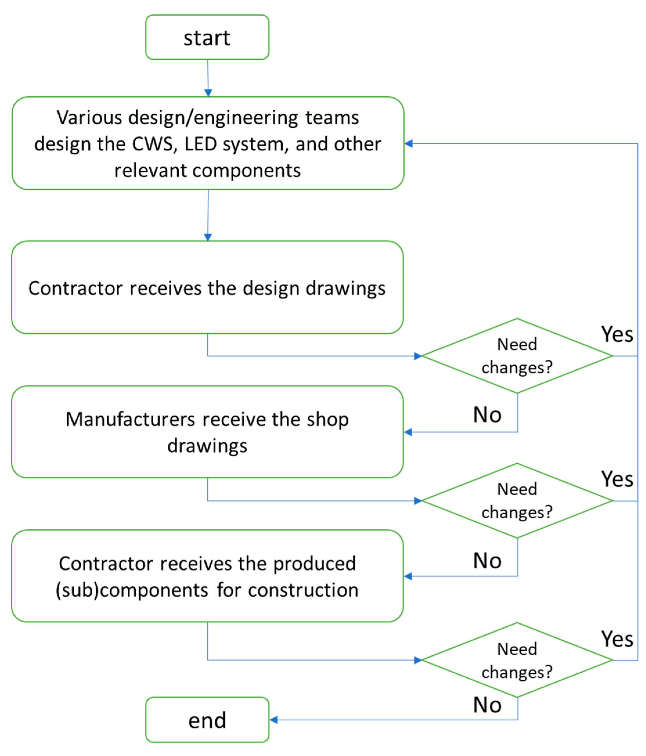
4.1. Conventional Design Process

Based on the information provided by all four interviewees, a conventional process for designing a CWS with an LED lighting system is described as follows (see Figure 1). As shown in Figure 1, at the first step, design engineers of Company A and design engineers of Company B develop design drawings of the CWS and LED lighting system, respectively. The finished design drawings are then delivered to the contractor for review. Note that this delivery is often through the client and sometimes is after integration with the entire building design, which is generally the responsibility of another design company. If the contractor requires any design changes, drawings will be returned to Company A and/or Company B. If no design changes are needed, the contractor will send drawings to manufacturers for producing the CWS and LED components. At the third step, manufacturers further review the drawings to check whether any design changes are needed. If the answer is yes, manufacturers will send the drawings back to the responsible design engineers; if not, they will proceed to the production work. At the fourth step, the produced CWS and LED components are delivered to the construction site for assembly. At this final step, design changes still could occur provided that confliction and other issues happened during the on-site assembly process.
Following the conventional design process, the design engineers only complete their work according to their own knowledge instead of incorporating knowledge from other disciplines. In this regard, these design engineers can be considered as knowing very little about the practical requirements of manufacture and assembly contingent on the entire project. All four interviewees have described such a process as “throwing things over the fence”: designers firstly finish design drawings and then throw them over the fence to the contractor and then to manufacturers. If design changes are required, the contractor and manufacturers just throw the drawings back to designers. This “over the fence” stylized process results in design changes frequently happening during stages subsequent to the design stage, which can jeopardize the performance of the project delivery.

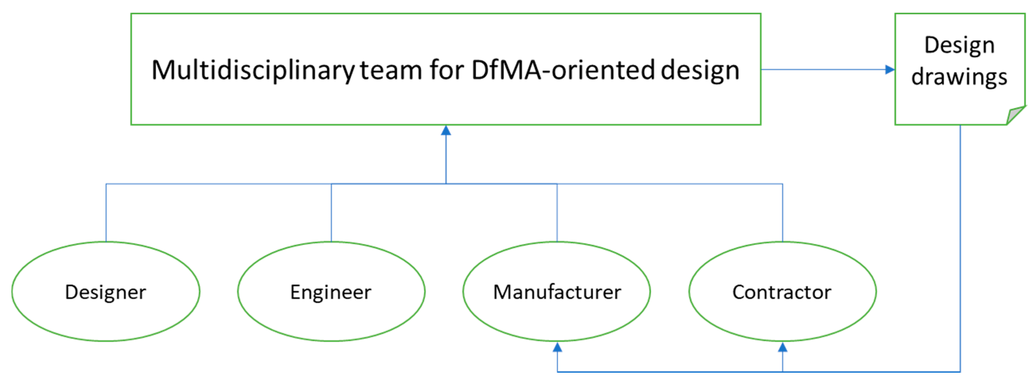
4.2. DfMA-Oriented Design Process

Subject to the risk of increased cost and time that is potentially raised by the conventional design process, the client decided to support the application of DfMA to the design of the CWS. The DfMA-oriented design process took two months, starting with forming a multidisciplinary team consisting of staff members who can report directly to the supervisory level, from the recruited design companies for the CWS design, the manufacturer, and the main contractor (see Figure 2). Through regular meetings of the multidisciplinary team, the knowledge, demands, and standards of different functional disciplines were communicated and discussed in a timely manner at the early stage of the project. The following contents introduce the DfMA-oriented design process with details.

4.2.1. DfMA Principles

The primary task that the multidisciplinary team addressed was to determine a set of DfMA principles contingent on the case project. The determined principles included (1) reducing the part count of the CWS, (2) reducing the numbers of unique fasteners necessary to assemble the CWS on the construction site, (3) using cost-effective materials, (4) making sure that the size and weight of components is easy to handle, and (5) reducing waste of materials. Guided by these five principles, the multidisciplinary team firstly chose which type of CWS should be used. Then, designers and engineers collaborated with each other to design the CWS, the exterior LED lighting system, and other building components that would affect the production and on-site assembly of the CWS and exterior LED lighting system. After that, staff members from the manufacturer and the main contractor reviewed the preliminary drawings in a timely manner before proceeding to the manufacturing and on-site assembly stages.

4.2.2. Unitized Curtain Wall System

A CWS could be either of the unitized type or of the stick type. A unitized CWS is composed of large units, of which the components are manufactured, assembled, and glazed in an off-site manufacturing factory; these large units are then delivered to the construction site and anchored to the constructed structures of the building. For a stick CWS, comparatively, all components such as vertical mullions, horizontal rails, and the glass or opaque panels are installed on-site piece by piece.
The multidisciplinary team recognized that the unitized type of CWS with interior glazing was preferable to the stick type for the case project. In the general sense, the assembly of the utilized CWS is relatively easier and faster—only one unit-to-unit splice (e.g., a translucent silicone patch) needs to be sealed on-site, and only one anchor per mullion needs to be attached to the face of the floor slab. In addition, the assembly of the utilized CWS can be conducted inside the building. Workers thus do not need to construct scaffoldings and stand on the cradles, which avoids falling from height and thereby contributes to on-site safety. Moreover, since the case project is a high-rise building with more than 30 floors that have identical exterior appearance, the use of a unitized CWS can take advantage of the mass production of monolithic curtain wall units in an off-site factory.

4.2.3. Adoption of Sustainable Materials

Guided by the DfMA principles, cost-effective, sustainable materials were used as much as possible in the CWS design. For example, the double silver Low-E glass, with radiation rate of 0.05, was adopted for the glass of the CWS unit. The multidisciplinary team also compared various types of materials for the back pan which is used to cover the structural beams of the building and provide the thermal and moisture protection. Based on the comparison results (see Table 3), a relatively new material, the 7 mm Eterpan, was selected since this type of material has advantages including appropriate weight, highest fire resistance rating, longest service life, and highest level of sustainability. Other materials, such as aluminum alloy frames and stainless bolts, were selected based on regulations and local market supplies.

4.2.4. Surface Treatment Methods

In this case project, the frame of the CWS unit was made up of aluminum alloy, requiring surface treatment to avoid corrosion. The multidisciplinary team compared three commonly adopted surface treatment methods: fluorine carbon coating, powder spray, and anodic oxidation (see Table 4). These three surface treatment methods have different unit prices, and different anticorrosion and aesthetic performances. Guided by the DfMA principles, (1) fluorine carbon coating was applied to the frame surface exposed to the outdoor environment since it has the highest resistance to corrosion; (2) powder spray was used to treat the frame surface exposed to the indoor environment due to its aesthetic advantage; and (3) anodic oxidation was applied to the unexposed surfaces because of its cheapest price. As expressed by the interviewed design engineers and the project manager, this combination of surface treatment methods could cost the least and achieve the best performance in protecting the frame.

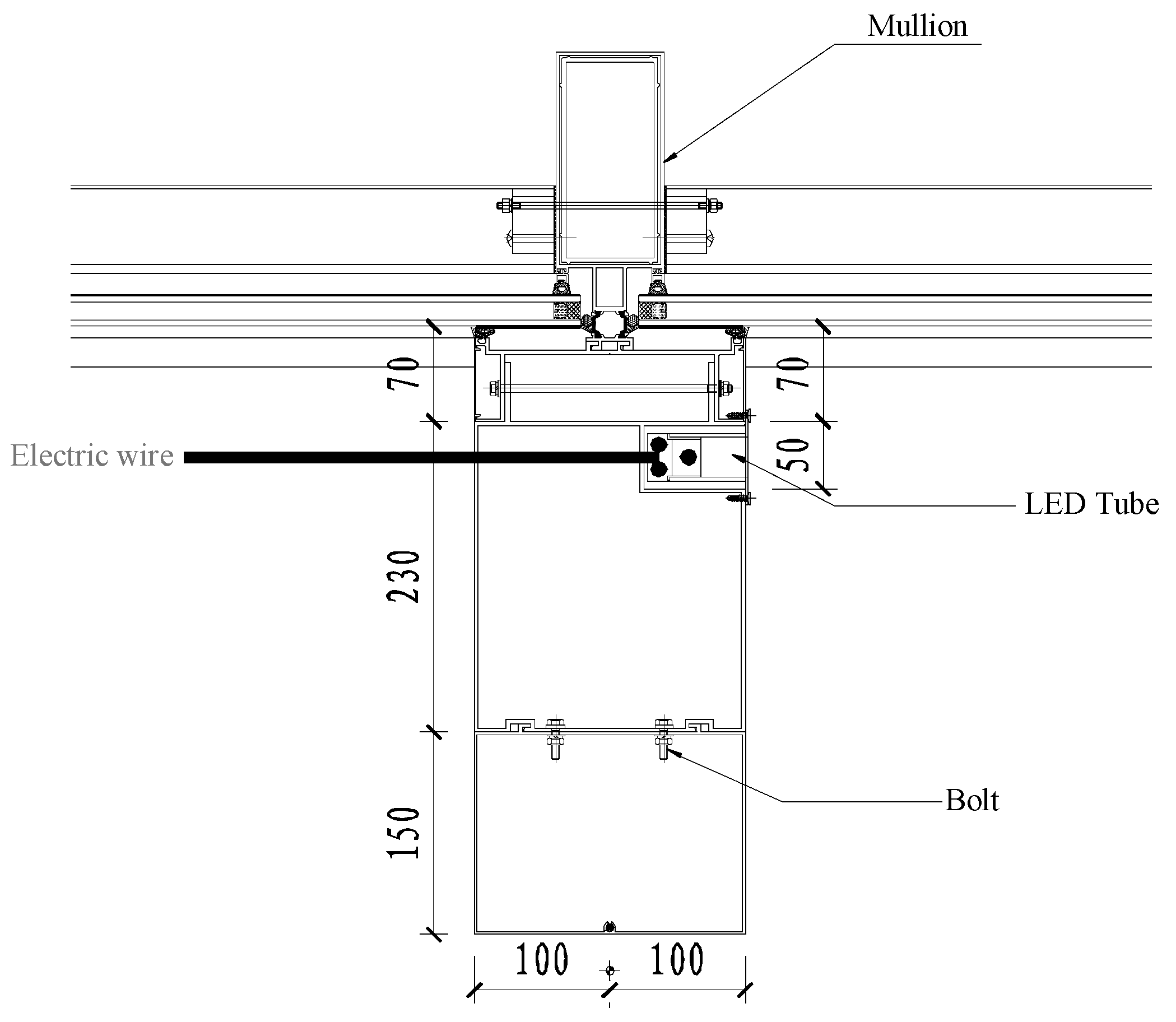
4.2.5. Integration of the CWS and Exterior LED Lighting System

A suggested by the contractor and agreed by the entire multidisciplinary team, the CWS and exterior LED lighting system were designed in an integrated manner via early collaboration between the design engineers of these two systems (see Figure 3). In this integrated design, the LED tube and electric wire were hidden inside the CWS. Such an integration can address the negative influences of exposed LED tubes and wires and ensure the attractive exterior appearance of the building in both day and night.

4.2.6. Integration of the CWS and Baseboard

The multidisciplinary team developed an integrated design of the CWS and baseboard (see Figure 4a), with an aim to address some important issues arising from a separated design (see Figure 4b). According to the interviewed project manager, in a separated design, the design styles of CWS and baseboard were often inconsistent. This inconsistency will require much interior space and workmanship for binding the separated CWS and baseboard. Comparatively, the integrated design of the CWS and baseboard could save the interior building space and reduce dependency on workmanship, and thereby contribute to the maximization of profitability and quality of the case project.

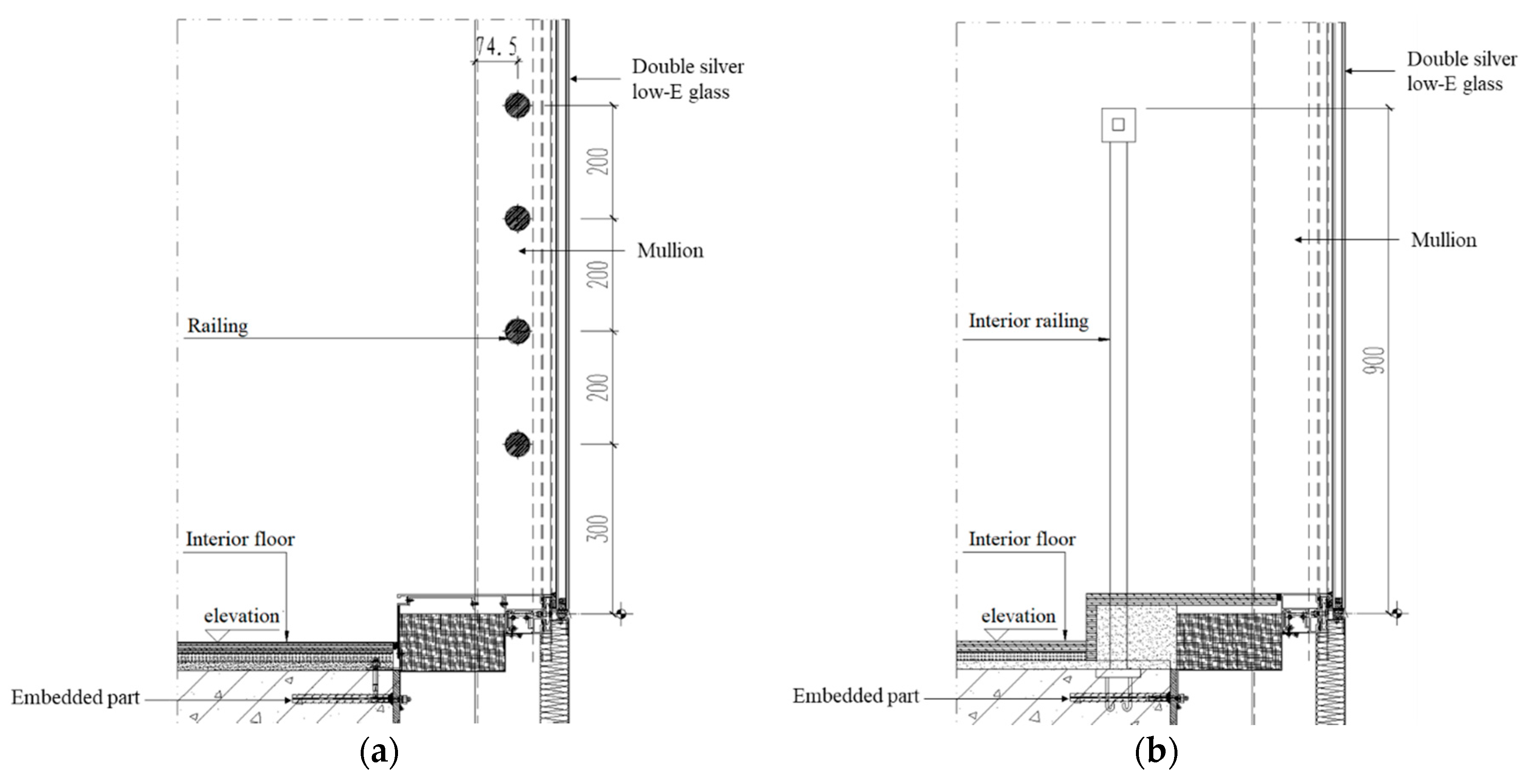
4.2.7. Integration of the CWS and Railing

The railing was also designed to be integrated with the CWS (see Figure 5a), which, as expressed by the interviewed project manager, merits a separated design (see Figure 5b). With a separated design, the construction of the railing should be done after the assembly of the CWS, resulting in additional labor work and interior space occupied by the separated railing. With an integrated design, in contrast, the railing would be fixed between studs in the frame of the CWS unit in the factory. That is, the construction of the railing was finished at the same time when the CWS was produced, which could save much interior space and labor force, and thereby contribute to the minimization of the project cost.

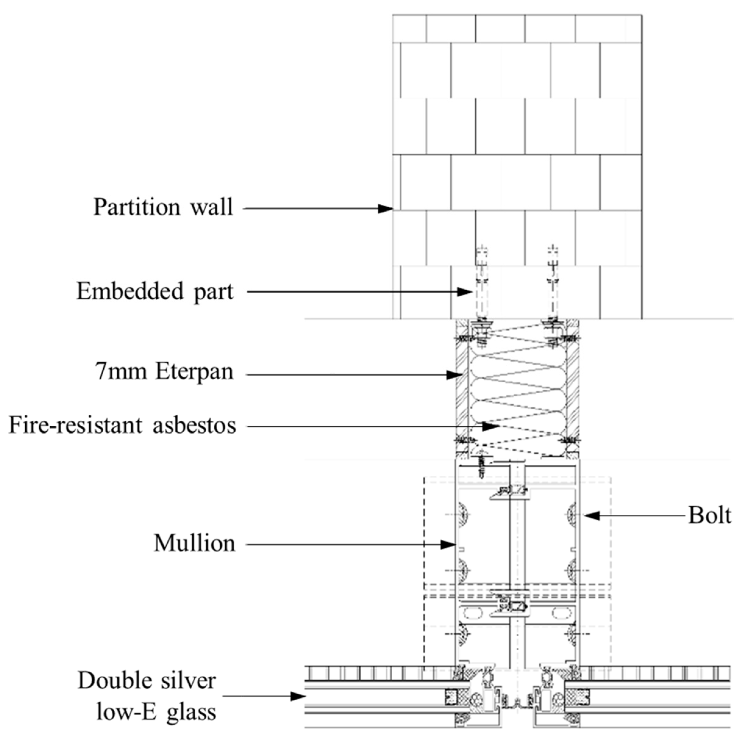
4.2.8. Connection between the CWS and Partition Wall

In this case project, each floor contained a number of office rooms that were separated by the partition walls. After the assembly of the CWS, a gap was formed between the partition wall and the mullion of the CWS. If unattended during the design stage, the gap could easily trigger problems such as smoke leakage and poor noise resistance, resulting in considerable costs for remedy at the maintenance and operation stage. To resolve these problems, the multidisciplinary team collaboratively designed a connection between the CWS and partition wall (see Figure 6). The connection consisted of two layers of 7 mm Eterpan with fire-resistant asbestos between (with the density of 100 kg/m3).

5. Benefits of DfMA Implementation in the Case Project

The implementation of the DfMA-oriented design process has improved the quality, enhanced the cost efficiency, and avoided generation of waste during the processes of manufacture and on-site assembly in the case project.

5.1. Benefits of DfMA to the Manufacturing Process

Via early participation in the CWS design, the manufacturer became more familiar with the detailed design and was thereby able to better perform the manufacturing work than before, which, as corroborated by the replies of the interviewed production manager, ensured quality and correctness for producing the CWS. Furthermore, at the regular meetings of the multidisciplinary team, the manufacturer had an opportunity to give opinions and suggestions on the final design and hence greatly contributed to the “manufacturability” of the CWS. Both the adoption of a unitized CWS and new materials like the colored 7 mm Eterpan, for example, were commonly agreed by the manufacturer, the contractor, and the designer.
As expressed by the interviewed production manager, the use of the unitized system has significantly (1) decreased the material cost, (2) improved the CWS quality owing to the controlled environment in the factory, and (3) decreased the generated pollution and waste of materials during the manufacturing process. By using the colored 7 mm Eterpan, for example, the unit price of the back pan was as low as US$9.38/m2. According to the interviewed design engineers, a back pan made up of typical materials in a conventional design reaches a unit price of US$24.25/m2. With about 6400 m2 of back pan in the building, using the 7 mm Eterpan was estimated to decrease the material cost by US$90,000. Moreover, since the use of typical materials also needs to be decorated with enameled glass for aesthetic purposes, the use of the colored 7 mm Eterpan reduced the required materials for making the back pan and thus contributed to the reduction of energy use and green gas emissions.

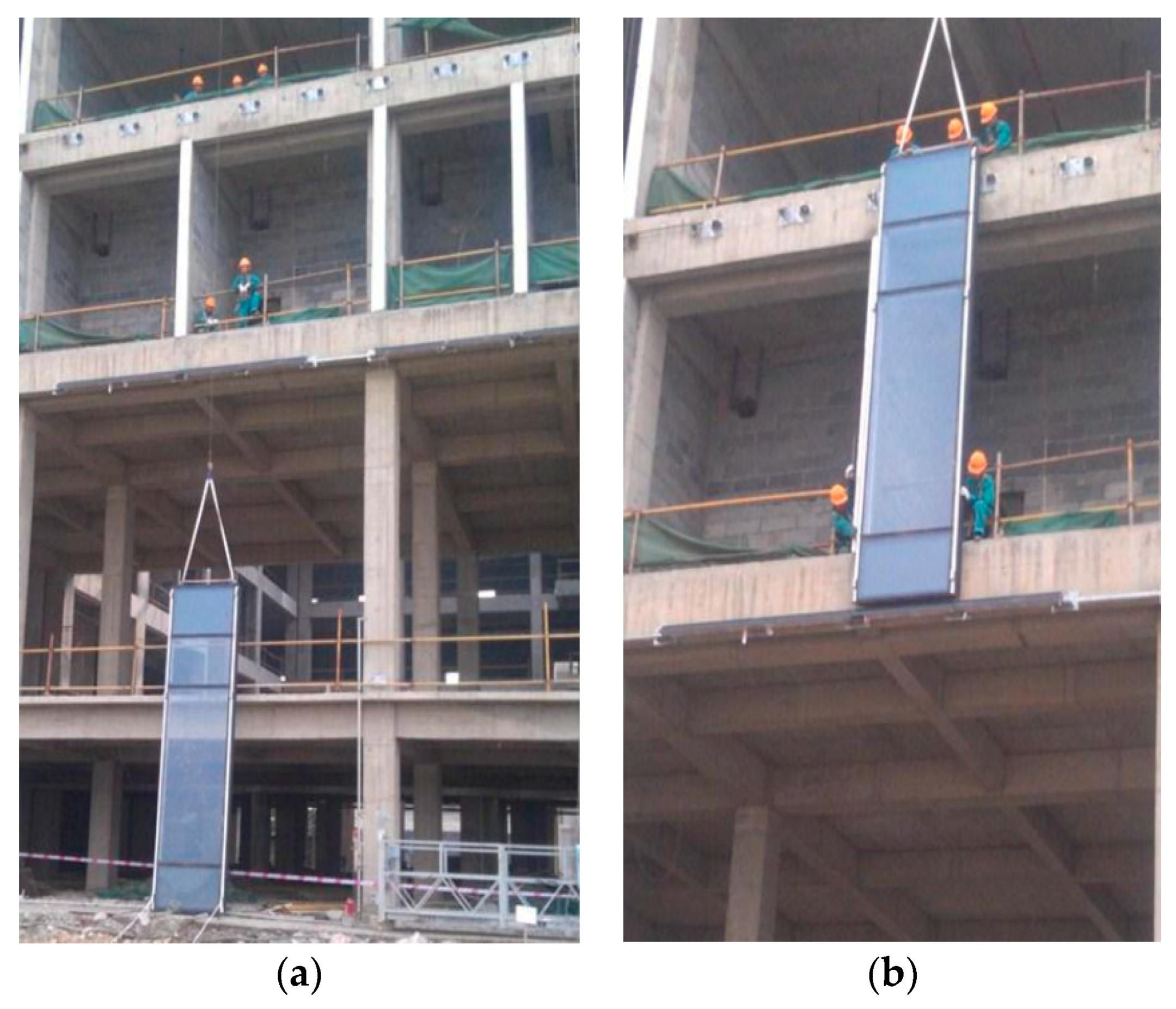
5.2. Benefits of DfMA to the On-Site Assembly Process

For the on-site assembly work, the interviewed project manager expressed that, by taking advantage of early communication between the contractor and the manufacturer in a DfMA-oriented design process, the probabilities of incorrect production were significantly reduced and, thereby, the logistics of the CWS components could be effectively managed to cope with the on-site assembly. Further, the adoption of a unitized CWS, new materials, etc., and the integrated design of the CWS and LED, baseboard, and railing have significantly facilitated the on-site assembly process. For instance, the interviewed project manager expressed that, compared with the stick type of CWS, the unitized CWS made the number of CWS components to assemble much smaller, greatly simplified the on-site assembly work, and thereby reduced the dependence on workmanship and increased the assembly correctness. The improved correctness of on-site assembly work also reduced waste generated during the construction process.
The time-efficiency of the on-site assembly was also increased by the DfMA-oriented CWS design, i.e., the use of a unitized CWS, and the integrated design of the CWS and LED, baseboard, and railing. As observed by the authors, each CWS unit was assembled through three steps (see Figure 7). Firstly, a unit was lifted by the hoist machine to the designated location. Then, workers aligned the CWS unit and installed sleeve and fastener accessors, which took the longest time among all steps. Finally, workers conducted the level measurement and assembled the CWS unit. These three steps can be done within 8 min: the produced CWS can be transferred to the designated location and aligned along with its vertical axis within 4 min; and the installation of sleeve and fastener accessors took less than 4 min. The interviewed project manager suggested that, when the CWS was designed following a conventional way, the average time taken for assembling one CWS unit could be over 15 min. Thus, the DfMA-oriented CWS design saved more than 7 min for assembly of one CWS unit. In addition, the assembly of the CWS unit can be within the scope of the current level of workmanship. The designed positional tolerance, i.e., ±2.0 mm, is sufficient to achieve easy assembly, while retaining waterproof and soundproof performance. No need for repair or re-assembly of a curtain wall unit was confirmed during the observation period.

5.3. Other Benefits

The DfMA implementation in the case project has also (1) improved the aesthetic performance of the CWS anchored to the case project, and (2) saved interior building space which, in turn, increased the profitability of the project delivery. The latter point was discussed in the above section. Here, an example of the former point is provided. Take the integrated design of the CWS and baseboard enabled by the DfMA-oriented design process as an example. Figure 8a presents a situation in which the CWS and baseboard were integrated through the DfMA-oriented design, while Figure 8b shows the connection of the CWS and baseboard in another project where the CWS and the baseboard were designed separately. A direct impression is the higher aesthetic performance of integrated design over the separate design. Last but not least, the DfMA application can be beneficial to the maintenance and operation stage. In particular, the use of double silver Low-E glass reduced the amount of solar radiation entering the building, which could contribute to the reduction of energy needed for maintaining indoor comfort cooling in such a hot, humid city as Wuhan. In addition, as introduced in Section 4.2.8, the connection between the CWS and partition wall designed in the DfMA process, as expressed by the interviewed design engineers and the project manager, could not only ensure easy on-site assembly, but also save costs for maintenance by avoiding smoke leakage and increasing noise resistance.

6. Discussion and Conclusions

This paper reported a case study of a real-life commercial building in Wuhan, in which DfMA principles were developed and applied to the design of the CWS. A multidisciplinary team was developed at the early project stage to generate design decisions by referring to several DfMA principles. The application results supported that the DfMA-oriented design could decrease material cost and waste, reduce the time required for on-site assembly, and improve the quality and aesthetic performance of the CWS. Several aspects of experience can be drawn from this case study.

6.1. Operative Multidisciplinary Team

Previous studies have shown that one of the major challenges in construction project management is to derive a design that attends contractors’ and manufacturers’ requirements while meeting the demands of the client [7,25,28,36,37,38]. By this token, forming an operative multidisciplinary team plays an important role in DfMA implementation in construction projects. This could be corroborated by the successful DfMA application in the case project as introduced in the above section.
Regarding the problem of how to develop an active multidisciplinary team, there are several points worthy of notice based on the experience from the case in this research. Firstly, it is a real challenge to balance between benefits derived from a multidisciplinary team to integrate knowledge as extensively as possible and the associated management cost. In this regard, it is probably easier to apply DfMA to projects delivered by integrated methods such as Design–Build [39] than to the Design–Bid–Build projects since the management cost for organizing a multidisciplinary team could somehow emerge with the cost of performing integrated delivery methods.
Secondly, the inclusion of project stakeholders should be contingent on the targets of the DfMA application in a particular project. For example, in the case study of this research, the multidisciplinary team included the staff members from all design companies recruited, the manufacturer, and the main contractor, with an aim of initiating a DfMA-oriented CWS design. Very differently, in the case study described in [7], the multidisciplinary team consisted of the client, contractor, architect, and structural engineer, with a more ambitious aim of increasing the constructability of an entire project. In their case study, however, the function of the multidisciplinary team did not fulfill expectations. Gerth et al. [7] found that, although they identified some shortages in the project design, the team members in their case did not show much interest in the on-site operations and lacked the knowledge of the exact order of assembly and so on.
Thirdly, it is important to select appropriate representatives of individual project stakeholders as members of the multidisciplinary team. The representatives must be of sufficient seniority to make decisions or be at a position that enables efficient decision-making as much as possible. This point is consistent with the argument of [36]. In the case project of this study, the multidisciplinary team members are staff members who can report to the supervisory level directly, which has not only significantly shortened the waiting time to make decisions, but also encouraged more frequent team meetings. The possible reason was that, if it was the managers themselves, instead of staff members, who needed to participate in the meetings, the associated opportunity cost might increase, considering the fact that managers would often be busy with other important issues.

6.2. Use of Digital, Parametric Design Platforms

In the case project, the design of the CWS was developed by using AutoCAD. When the design was changed based on the DfMA principles, the multidisciplinary team manually updated all corresponding drawings and re-analyzed the updated design, like recalculating the material cost. This manual work-intensive process could be improved by using a more advanced digital, parametric design platform. Parametric design is a process based on algorithmic thinking that enables the expression of parameters and rules that, together, define, encode, and clarify the relationship between design intent and design response [40]. In the manufacturing industry, mature digital design platforms have been widely used for the implementation of DfMA principles in product design. In the construction industry, there is also emerging increasing attention to the adoption of digital, parametric design platforms such as building information modeling (BIM) [41,42,43,44]. When trying to implement DfMA-oriented design in a construction project, practitioners are suggested to consider the use of such digital, parametric design platforms [45].

6.3. Limitation and Future Research

The current findings are limited to a case study of a single commercial building project. However, these findings can still contribute to the general understanding of the DfMA-oriented design of a CWS. Future research can be conducted to study the application of a DfMA-oriented design approach to other types of facilities. In addition, further research is needed to detect the relationship between the forming of a multidisciplinary team and the targets of DfMA applications, project types, etc. Further research also can be conducted to explore the application of BIM to support DfMA-oriented design in various types of construction projects.

Author Contributions

K.C. is the primary author of this paper; W.L. was involved in redrafting the paper following reviewers’ comments.

Funding

This research received no external funding.

Acknowledgments

The authors would like to thank Yuan Liao for providing project documents and helping arrange interviews and on-site observations. The authors would like to thank all editors and reviewers for their constructive comments.

Conflicts of Interest

The authors declare no conflict of interest.

References

  1. Al-Hammad, A.-M.; Hassanain, M.A.; Juaim, M.N. Evaluation and selection of curtain wall systems for medium-high rise building construction. Struct. Surv. 2014, 32, 299–314. [Google Scholar] [CrossRef]
  2. Cuce, E.; Riffat, S.B.; Young, C.-H. Thermal insulation, power generation, lighting and energy saving performance of heat insulation solar glass as a curtain wall application in Taiwan: A comparative experimental study. Energy Convers. Manag. 2015, 96, 31–38. [Google Scholar] [CrossRef]
  3. Oh, M.; Tae, S.; Hwang, S. Analysis of Heating and Cooling Loads of Electrochromic Glazing in High-Rise Residential Buildings in South Korea. Sustainability 2018, 10, 1121. [Google Scholar] [CrossRef]
  4. Azari-N, R.; Kim, Y.-W. Comparative assessment of life cycle impacts of curtain wall mullions. Build. Environ. 2012, 48, 135–145. [Google Scholar] [CrossRef]
  5. Klein, T. Integral Facade Construction: Towards a New Product Architecture for Curtain Walls; Delft University of Technology: Delft, The Netherlands, 2013. [Google Scholar]
  6. Dubois, A.; Gadde, L.-E. The construction industry as a loosely coupled system: Implications for productivity and innovation. Constr. Manag. Econ. 2002, 20, 621–631. [Google Scholar] [CrossRef]
  7. Gerth, R.; Boqvist, A.; Bjelkemyr, M.; Lindberg, B. Design for construction: Utilizing production experiences in development. Constr. Manag. Econ. 2013, 31, 135–150. [Google Scholar] [CrossRef]
  8. Liu, X.; Cui, Q.; Schwartz, C. Greenhouse gas emissions of alternative pavement designs: Framework development and illustrative application. J. Environ. Manag. 2014, 132, 313–322. [Google Scholar] [CrossRef] [PubMed]
  9. Kent, D.C.; Becerik-Gerber, B. Understanding Construction Industry Experience and Attitudes toward Integrated Project Delivery. J. Constr. Eng. Manag. 2010, 136, 815–825. [Google Scholar] [CrossRef]
  10. Yuan, Z.; Sun, C.; Wang, Y. Design for Manufacture and Assembly-oriented parametric design of prefabricated buildings. Autom. Constr. 2018, 88, 13–22. [Google Scholar] [CrossRef]
  11. Molloy, O.; Warman, E.A.; Tilley, S. Design for Manufacturing and Assembly: Concepts, Architectures and Implementation; Springer Science & Business Media: Berlin, Germany, 2012; ISBN 978-1-4615-5785-2. [Google Scholar]
  12. Martínez, S.; Jardón, A.; Gonzalez Víctores, J.; Balaguer, C. Flexible field factory for construction industry. Assem. Autom. 2013, 33, 175–183. [Google Scholar] [CrossRef] [Green Version]
  13. Mara, V.; Kliger, R. An approach to the development of connections between fibre reinforced polymer bridge decks. Case Stud. Struct. Eng. 2016, 5, 18–26. [Google Scholar] [CrossRef]
  14. Belay, A.M. Design for Manufacturability and Concurrent Engineering for Product Development; CIM Pr: San Diego, CA, USA, 2009; Volume 3, p. 7. [Google Scholar]
  15. El-Nounu, A.; Popov, A.; Ratchev, S. Redesign methodology for mechanical assembly. Res. Eng. Des. 2018, 29, 107–122. [Google Scholar] [CrossRef]
  16. Mesa, J.; Maury, H.; Arrieta, R.; Corredor, L.; Bris, J. A novel approach to include sustainability concepts in classical DFMA methodology for sheet metal enclosure devices. Res. Eng. Des. 2018, 29, 227–244. [Google Scholar] [CrossRef]
  17. Rausch, C.; Nahangi, M.; Perreault, M.; Haas, C.T.; West, J. Optimum Assembly Planning for Modular Construction Components. J. Comput. Civ. Eng. 2017, 31, 04016039. [Google Scholar] [CrossRef]
  18. Peterseim, J.H.; White, S.; Hellwig, U. Novel solar tower structure to lower plant cost and construction risk. AIP Conf. Proc. 2016, 1734, 070025. [Google Scholar] [CrossRef] [Green Version]
  19. Kim, M.-K.; McGovern, S.; Belsky, M.; Middleton, C.; Brilakis, I. A Suitability Analysis of Precast Components for Standardized Bridge Construction in the United Kingdom. Procedia Eng. 2016, 164, 188–195. [Google Scholar] [CrossRef]
  20. Ramaji, I.J.; Memari, A.M.; Messner, J.I. Product-Oriented Information Delivery Framework for Multistory Modular Building Projects. J. Comput. Civ. Eng. 2017, 31, 04017001. [Google Scholar] [CrossRef]
  21. Banks, C.; Kotecha, R.; Curtis, J.; Dee, C.; Pitt, N.; Papworth, R. Enhancing High-Rise Residential Construction Through Design for Manufacture and Assembly. In Proceedings of the Institution of Civil Engineers—Management, Procurement and Law; ICE: London, UK, 2018; pp. 1–36. [Google Scholar] [CrossRef]
  22. Bridgewater, C. Principles of design for automation applied to construction tasks. Autom. Constr. 1993, 2, 57–64. [Google Scholar] [CrossRef]
  23. Anumba, C.J.; Baugh, C.; Khalfan, M.M.A. Organisational structures to support concurrent engineering in construction. Ind. Manag. Data Syst. 2002, 102, 260–270. [Google Scholar] [CrossRef]
  24. Fox, S.; Marsh, L.; Cockerham, G. Design for manufacture: A strategy for successful application to buildings. Constr. Manag. Econ. 2001, 19, 493–502. [Google Scholar] [CrossRef]
  25. Pasquire, C.L.; Connolly, G.E. Design for manufacture and assembly. In Proceedings of the 11th Annual Conference of the International Group for Lean Construction, Blacksburg, VA, USA, 22–23 July 2003. [Google Scholar]
  26. Love, P.E.; Gunasekaran, A.; Li, H. Concurrent engineering: A strategy for procuring construction projects. Int. J. Proj. Manag. 1998, 16, 375–383. [Google Scholar] [CrossRef]
  27. Caillaud, E.; Gourc, D.; Garcia, L.A.; Crossland, R.; McMahon, C. A Framework for a Knowledge-Based System for Risk Management in Concurrent Engineering. Concurr. Eng. 1999, 7, 257–267. [Google Scholar] [CrossRef] [Green Version]
  28. Moore, D. Buildability assessment and the development of an automated design aid for managing the transfer of construction process knowledge. Eng. Constr. Archit. Manag. 1996, 3, 29–46. [Google Scholar] [CrossRef]
  29. Machado, M.; Underwood, J.; Fleming, A. Implementing BIM to Streamline a Design, Manufacture, and Fitting Workflow: A Case Study on a Fit-Out SME in the UK. Int. J. 3D Inf. Model. 2016, 5, 31–46. [Google Scholar] [CrossRef]
  30. Martinez, S.; Balaguer, C.; Jardon, A.; Navarro, J.M.; Gimenez, A.; Barcena, C. Robotized Lean Assembly in the Building Industry. In Proceedings of the 25th International Symposium on Automation and Robotics in Construction, Vilnius, Lithuania, 26–29 June 2008; pp. 195–201. [Google Scholar]
  31. Jensen, P.; Lidelöw, H.; Olofsson, T. Product configuration in construction. Int. J. Mass Cust. 2015, 5, 73. [Google Scholar] [CrossRef]
  32. Goulding, J.S.; Rahimian, F.P.; Arif, M.; Sharp, M.D. New offsite production and business models in construction: Priorities for the future research agenda. Archit. Eng. Des. Manag. 2015, 11, 163–184. [Google Scholar] [CrossRef]
  33. Flyvbjerg, B. Five Misunderstandings About Case-Study Research. Qual. Inq. 2006, 12, 219–245. [Google Scholar] [CrossRef] [Green Version]
  34. Yin, R.K. Case Study Research and Applications: Design and Methods; SAGE Publications: Thousand Oaks, CA, USA, 2017; ISBN 978-1-5063-3618-3. [Google Scholar]
  35. Rabionet, S.E. How I Learned to Design and Conduct Semi-structured Interviews: An Ongoing and Continuous Journey. Qual. Rep. 2011, 16, 563–566. [Google Scholar]
  36. Anumba, C.J.; Evbuomwan, N.F.O. Concurrent engineering in design-build projects. Constr. Manag. Econ. 1997, 15, 271–281. [Google Scholar] [CrossRef]
  37. Lam, P.T.I.; Wong, F.W.H. Improving building project performance: How buildability benchmarking can help. Constr. Manag. Econ. 2009, 27, 41–52. [Google Scholar] [CrossRef]
  38. Montali, J.; Overend, M.; Pelken, P.M.; Sauchelli, M. Knowledge-Based Engineering in the design for manufacture of prefabricated façades: Current gaps and future trends. Archit. Eng. Des. Manag. 2018, 14, 78–94. [Google Scholar] [CrossRef]
  39. Hale, D.R.; Shrestha, P.P.; Gibson, G.E.; Migliaccio, G.C. Empirical Comparison of Design/Build and Design/Bid/Build Project Delivery Methods. J. Constr. Eng. Manag. 2009, 135, 579–587. [Google Scholar] [CrossRef] [Green Version]
  40. Jabi, W. Parametric Design for Architecture; Laurence King Publ.: London, UK, 2013; ISBN 978-1-78067-314-1. [Google Scholar]
  41. Eastman, C.M.; Teicholz, P.; Sacks, R.; Liston, K. BIM Handbook: A Guide to Building Information Modeling for Owners, Managers, Designers, Engineers and Contractors; John Wiley & Sons: Hoboken, NJ, USA, 2011; ISBN 978-0-470-54137-1. [Google Scholar]
  42. Jeong, W.; Kim, K.H. A Performance Evaluation of the BIM-Based Object-Oriented Physical Modeling Technique for Building Thermal Simulations: A Comparative Case Study. Sustainability 2016, 8, 648. [Google Scholar] [CrossRef]
  43. Chen, K.; Lu, W.; Wang, H.; Niu, Y.; Huang, G.G. Naming Objects in BIM: A Convention and a Semiautomatic Approach. J. Constr. Eng. Manag. 2017, 143, 06017001. [Google Scholar] [CrossRef] [Green Version]
  44. Alwisy, A.; Hamdan, S.B.; Barkokebas, B.; Bouferguene, A.; Al-Hussein, M. A BIM-based automation of design and drafting for manufacturing of wood panels for modular residential buildings. Int. J. Constr. Manag. 2018, in press. [Google Scholar] [CrossRef]
  45. Nath, T.; Attarzadeh, M.; Tiong, R.L.K.; Chidambaram, C.; Yu, Z. Productivity improvement of precast shop drawings generation through BIM-based process re-engineering. Autom. Constr. 2015, 54, 54–68. [Google Scholar] [CrossRef]
Figure 1. Conventional design process.
Sustainability 10 02211 g001
Figure 2. Multidisciplinary team for implementing the DfMA-oriented design.
Sustainability 10 02211 g002
Figure 3. Integrated design of the CWS and exterior LED lighting system.
Sustainability 10 02211 g003
Figure 4. (a) Integrated design of the CWS and baseboard; (b) separated design of the CWS and baseboard.
Sustainability 10 02211 g004aSustainability 10 02211 g004b
Figure 5. (a) Integrated design of the CWS and railing; (b) separated design of the CWS and railing.
Sustainability 10 02211 g005
Figure 6. Design of the connection between the CWS and partition wall.
Sustainability 10 02211 g006
Figure 7. (a) Lifting the curtain wall unit; (b) on-site assembly of the curtain wall unit.
Sustainability 10 02211 g007
Figure 8. (a) Integrated design of the CWS and baseboard in the case project; (b) conventional design of the CWS and baseboard in another project.
Sustainability 10 02211 g008
Table 1. Empirical studies on design for manufacture and assembly (DfMA) implementation in construction projects.
PublicationType of Facilities or ComponentsConstructs of DfMA Principles
[7]The light wall of a building1. Reducing material cost.
2. Minimizing complex operations.
[18]One solar tower1. Minimizing manufacturing cost by used pre-assembled modules.
2. Minimizing assembly and transport costs.
[19]The superstructure and substructure of a bridge1. Minimizing the number of parts.
2. Simplifying the fabrication and assembly steps.
3. Using standardized and common components and materials.
4. The size and weight of components should be easy to handle.
5. Minimizing the steps of jointing and fastening.
[13]Connection of fiber-reinforced polymer bridge decks1. The connection should not be tolerance tight.
2. Minimizing on-site bonded connections and fasteners.
3. Reducing the number of parts in assembly.
4. Minimizing movement and rotation.
5. Maximum repetition and standardization.
[20]Two four-story student dormitory buildings1. Suitable size and weight of modules.
2. Suitable size of the gaps between modules.
3. Fitting the site logistics and schedule.
[21]72% of the frame and façade of a residential building, bathroom pods, and mechanical, electrical, and plumbing (MEP) elements1. Reducing the number of unique parts.
2. Using standardized prefabricated elements and modules.
3. Simplifying the joint of components.
4. Minimizing temporary structure.
5. Decreasing waste of materials.
Table 2. Data collected in the case study.
Data CollectedSourcePurpose(s)
Project descriptionProject documentsTo understand the basic information of the project.
The workflow of the conventional design processSemistructured interviewsTo understand the conventional design process.
The workflow of the DfMA-oriented design processSemistructured interviews; project documents; meeting minutesTo understand the DfMA-oriented design process.
Design drawingsProject documentsTo understand the generated design.
Feedback on the DfMA-oriented design and the generated design drawingsSemistructured interviewsTo understand the stakeholders’ opinions about the DfMA-oriented design.
The conventional process and the DfMA-oriented process for the curtain wall system (CWS) designSemistructured interviews; on-site observationTo understand the impacts of the DfMA-oriented design on the construction process.
Table 3. Comparison of various materials for the back pan 1.
Material Types7 mm Eterpan7 mm Calcium Silicate Board4 mm Composite Aluminum Plate2 mm Aluminum Plate
Compositionfiber-reinforced cement, quartz powder, iron oxide, water, and so on.cement, coal ash, calcium powder, silicate powder, asbestos, pulp, water, and so on.aluminum, polyvinyl chloride (PVC), and so on.aluminum, magnesium, manganese, copper, and so on.
Manufacturing technologyContinuous rollingPrecastContinuous rollingContinuous rolling
Size (mm × mm)1220 × 24401220 × 24401220 × 24401500 × 4000
Fire resistance ratingA1 (highest)ACombustibleA
ChromatismYesYesYesYes
Service life (year)60 (earthquake resistant)155–155–15
Unit price (US$/m2)9.46.218.732.7
SustainabilitySustainableNoHighly pollutedHighly polluted
1: Information was provided by the interviewees.
Table 4. Comparison of three surface treatment methods 1.
Surface Treatment MethodFluorine Carbon CoatingPowder SprayAnodic Oxidation
Corrosion resistanceHighMediumMedium
Aesthetic performanceMediumHighLow
Unit price (per kg)US$5.3US$3.6US$3.4
1: Information was provided by the interviewees.

