Comparative Study of Frequency Converters for Doubly Fed Induction Machines

Abstract
:1. Introduction
2. Modeling Methodology
3. Two-Level Frequency Converter and an Asynchronous Generator Motor
4. Three-Level Frequency Converter and an Asynchronous Generator Motor
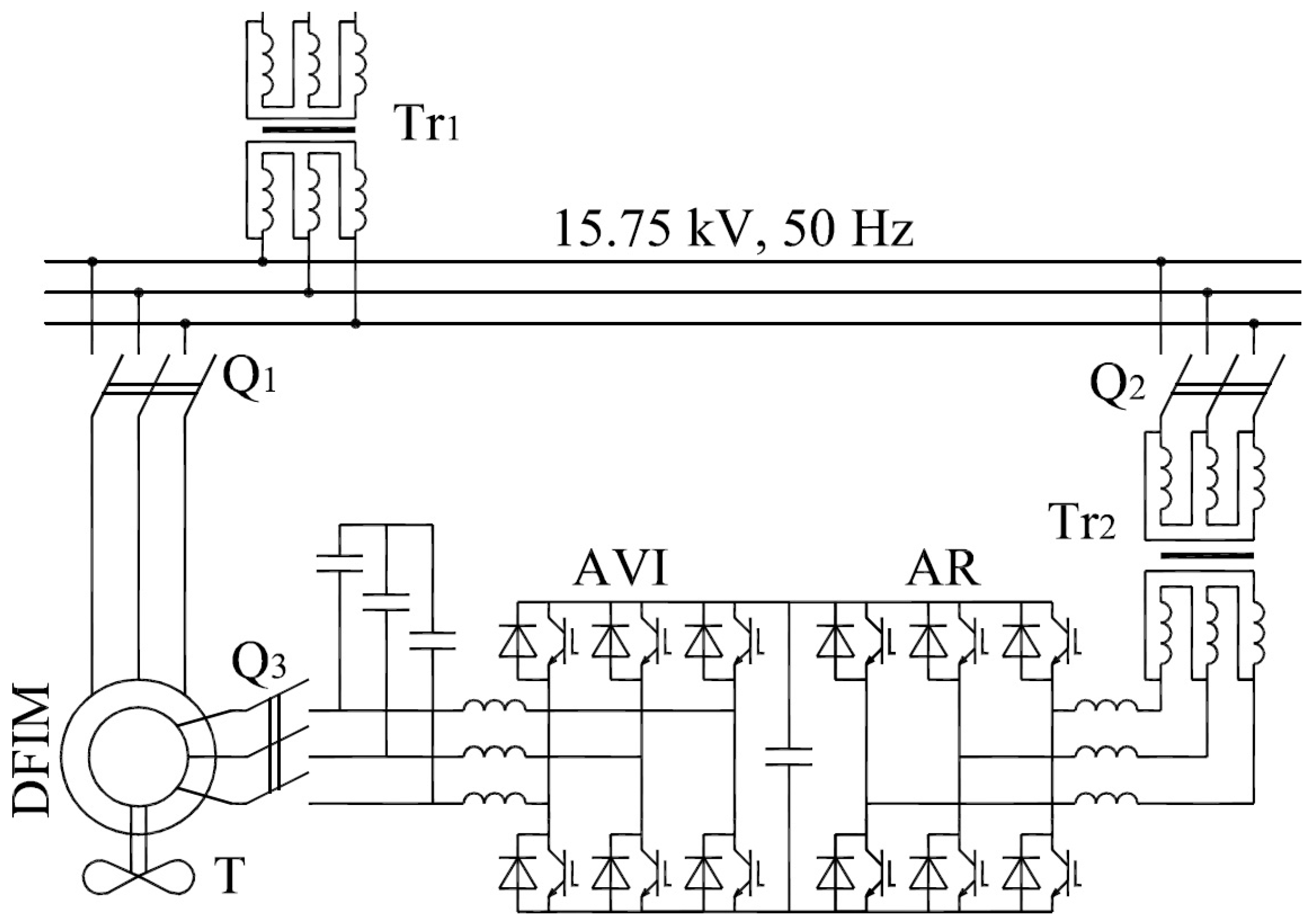
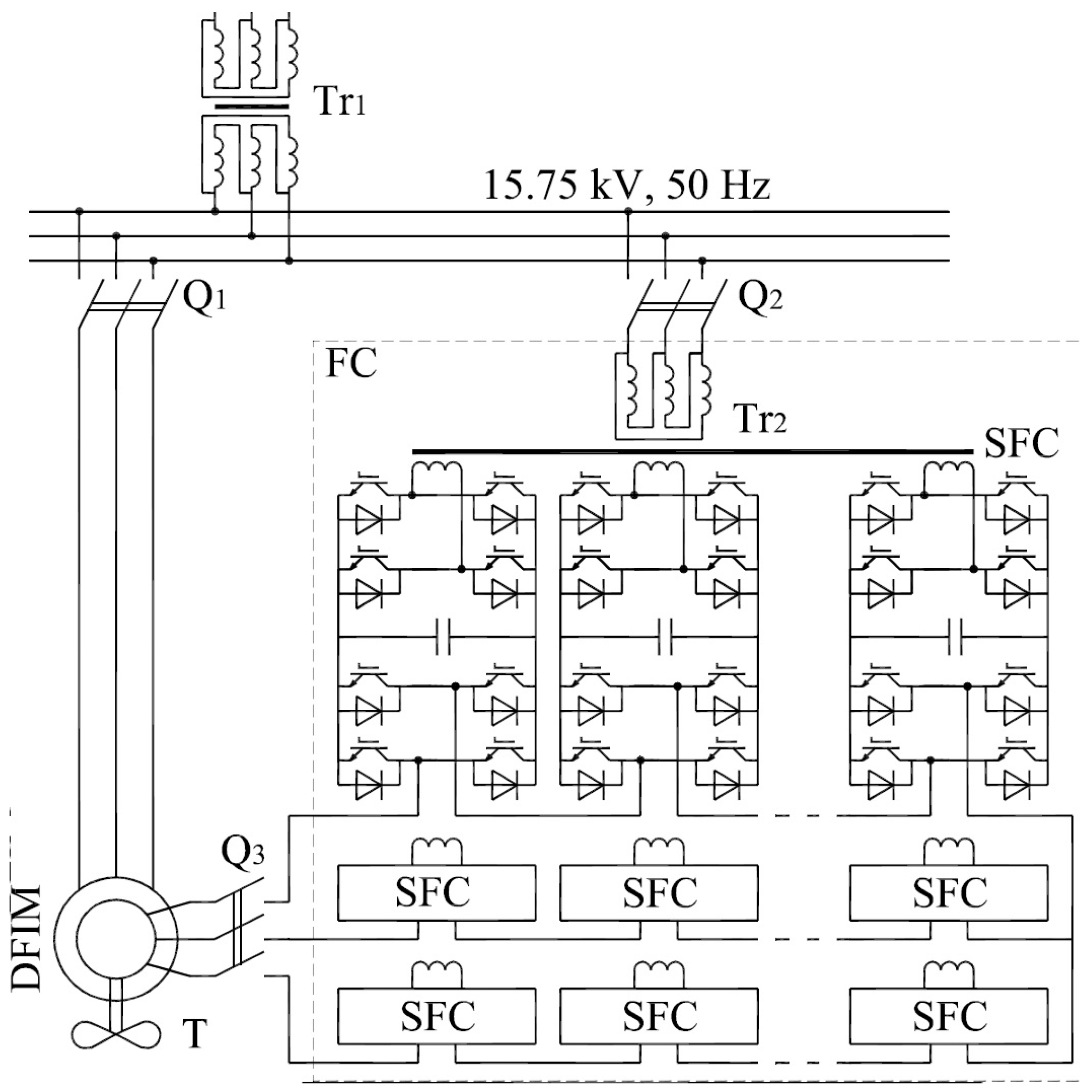
5. Cascade Frequency Converter and an Asynchronous Generator Motor
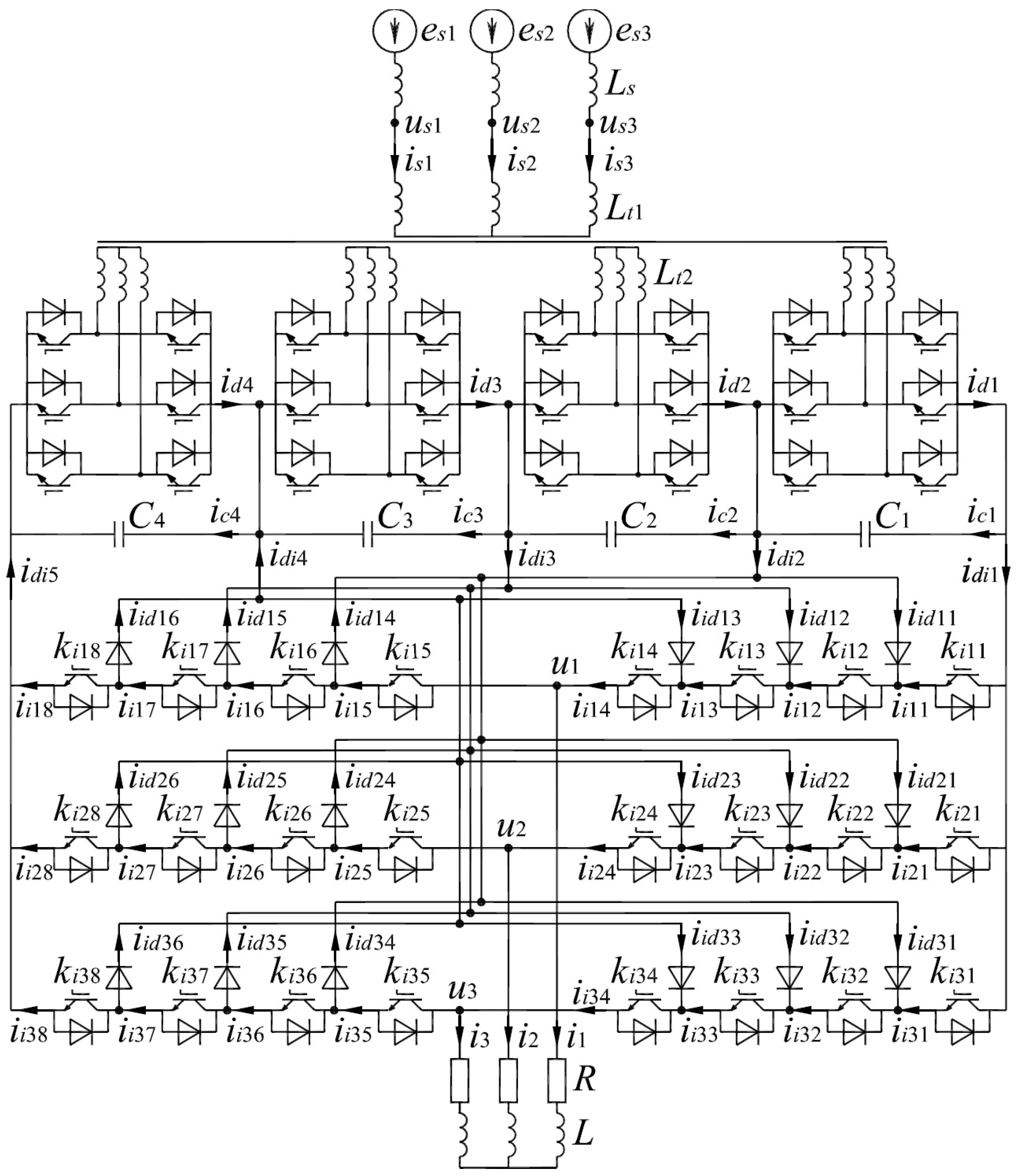
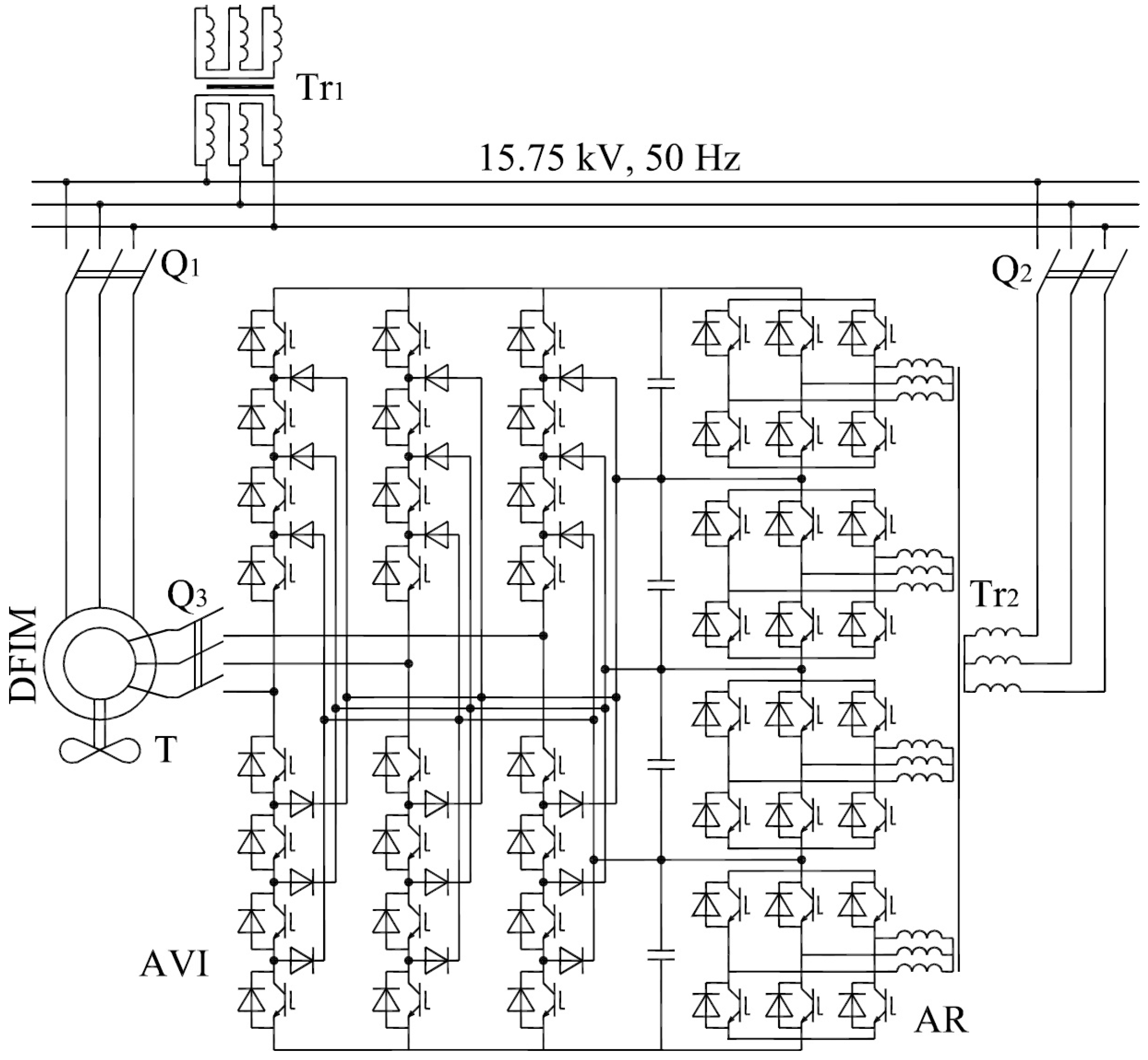
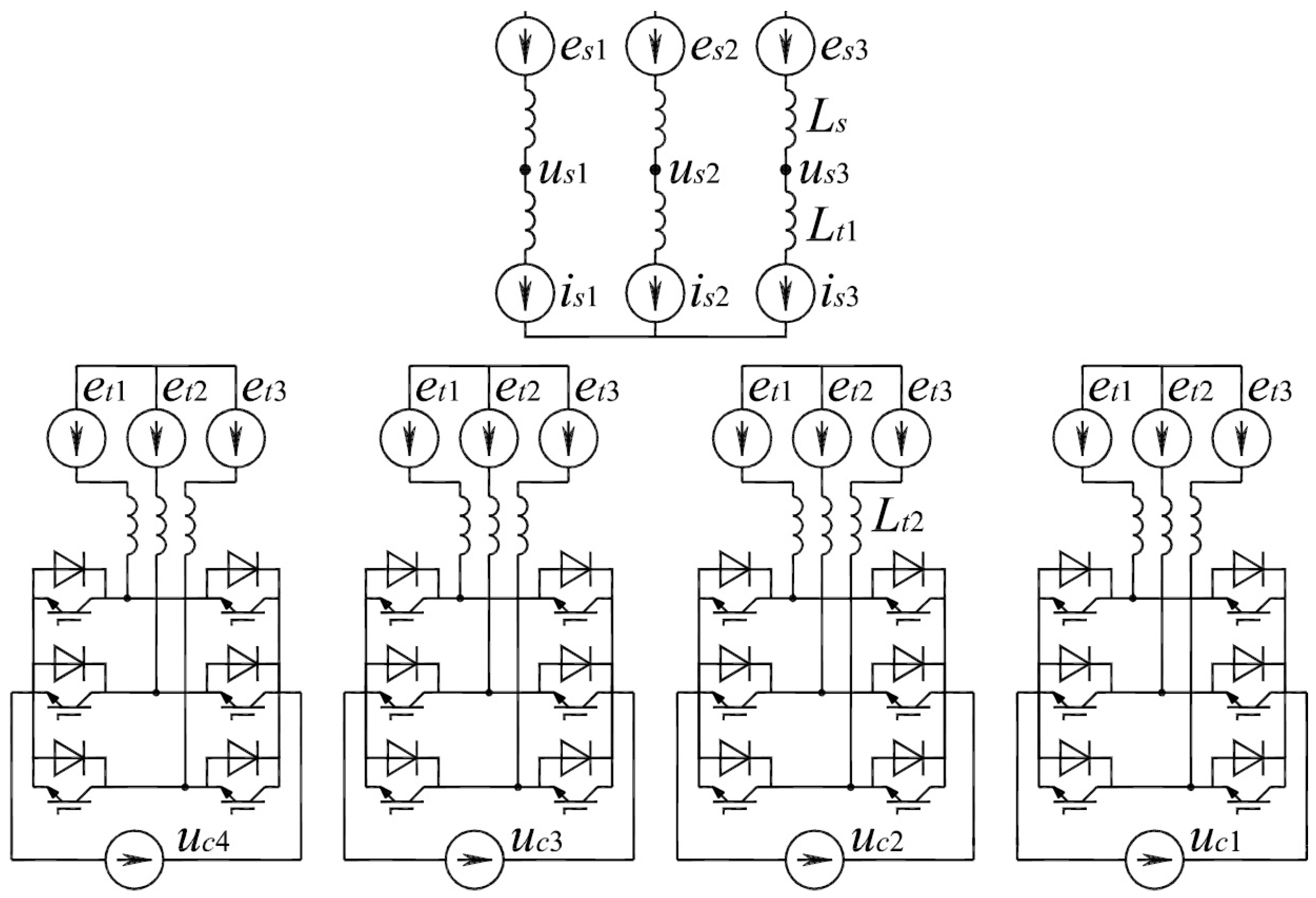
6. Multistage-Multilevel Frequency Converter and an Asynchronous Generator-Motor
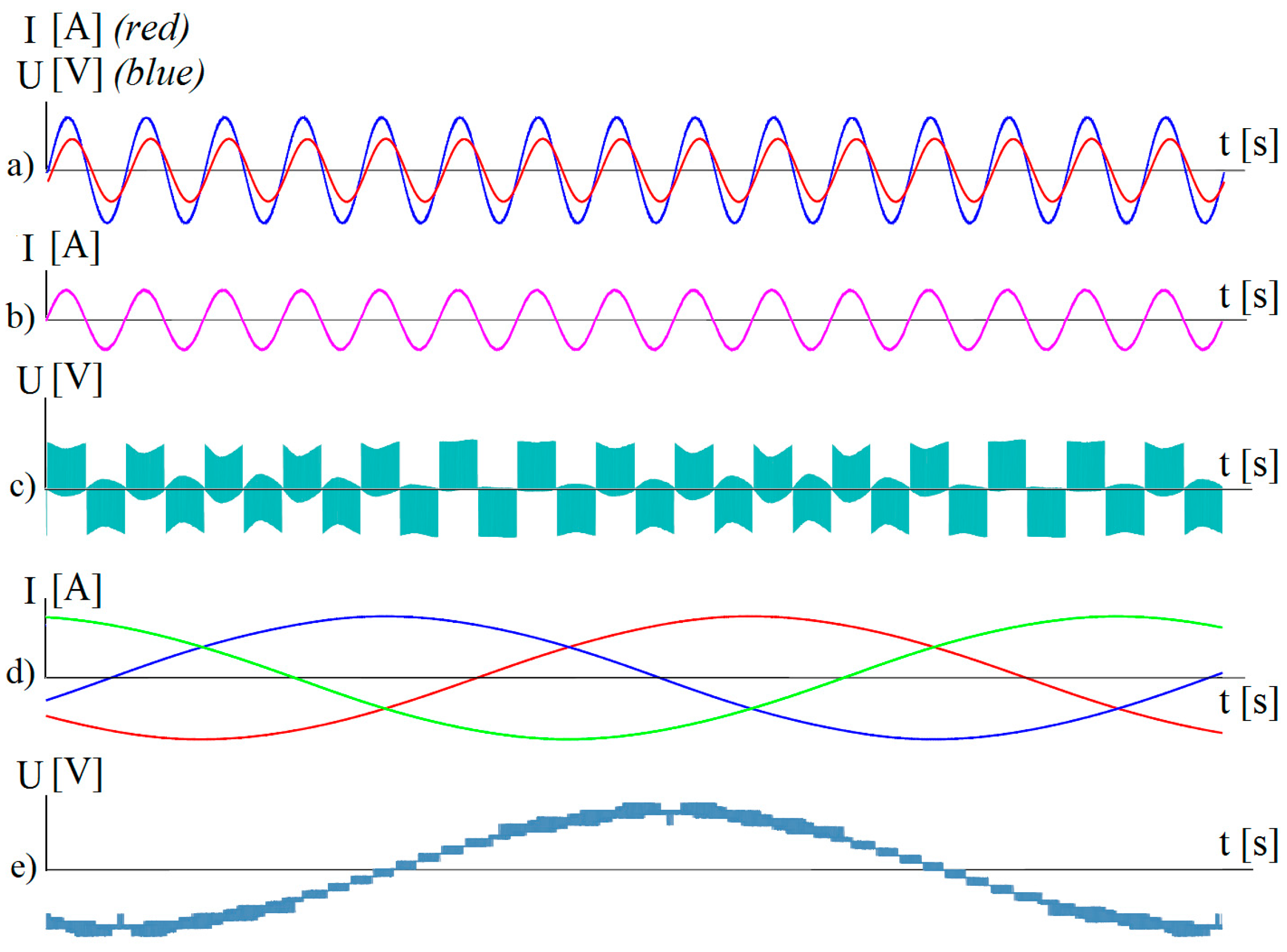
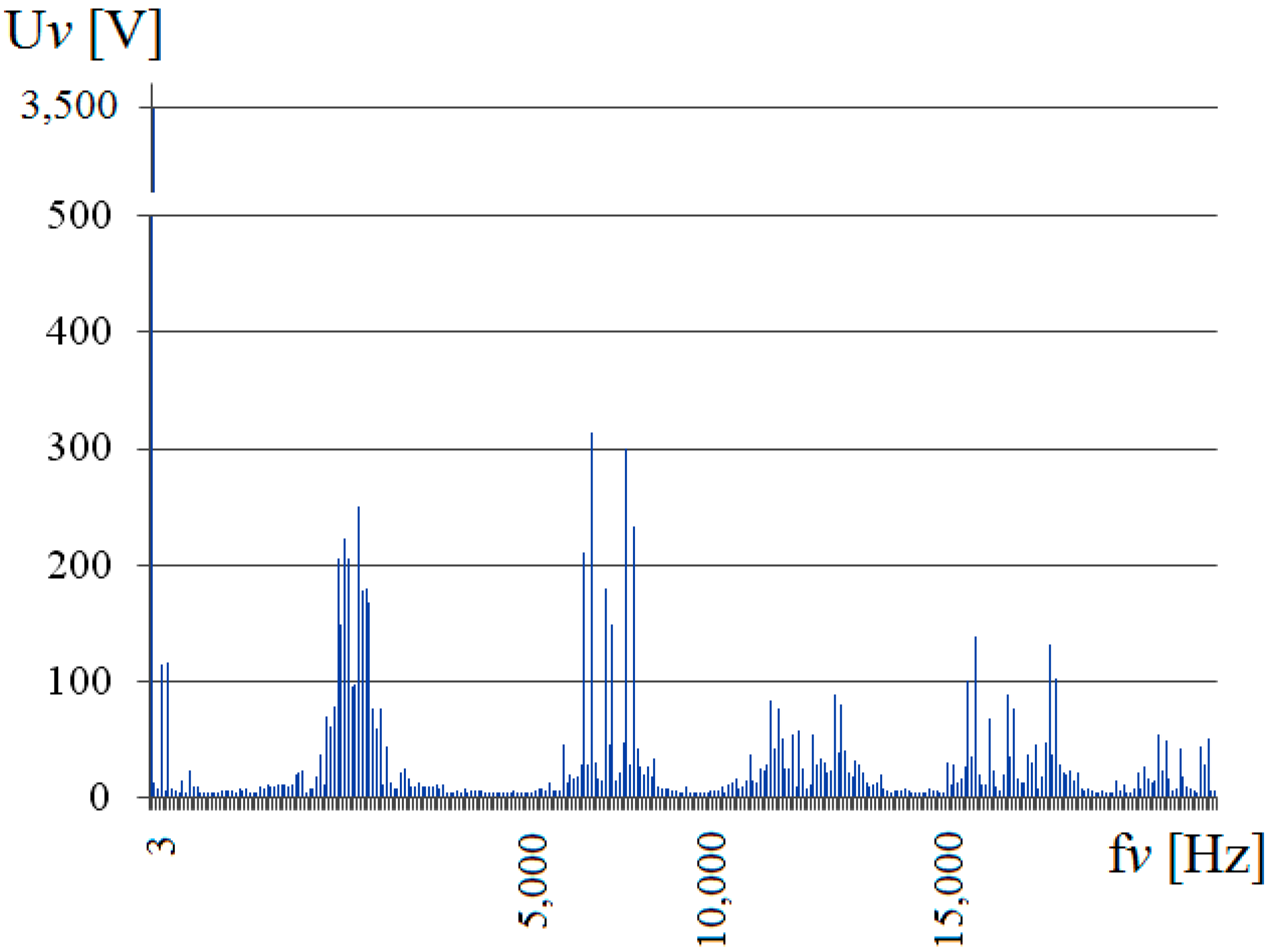
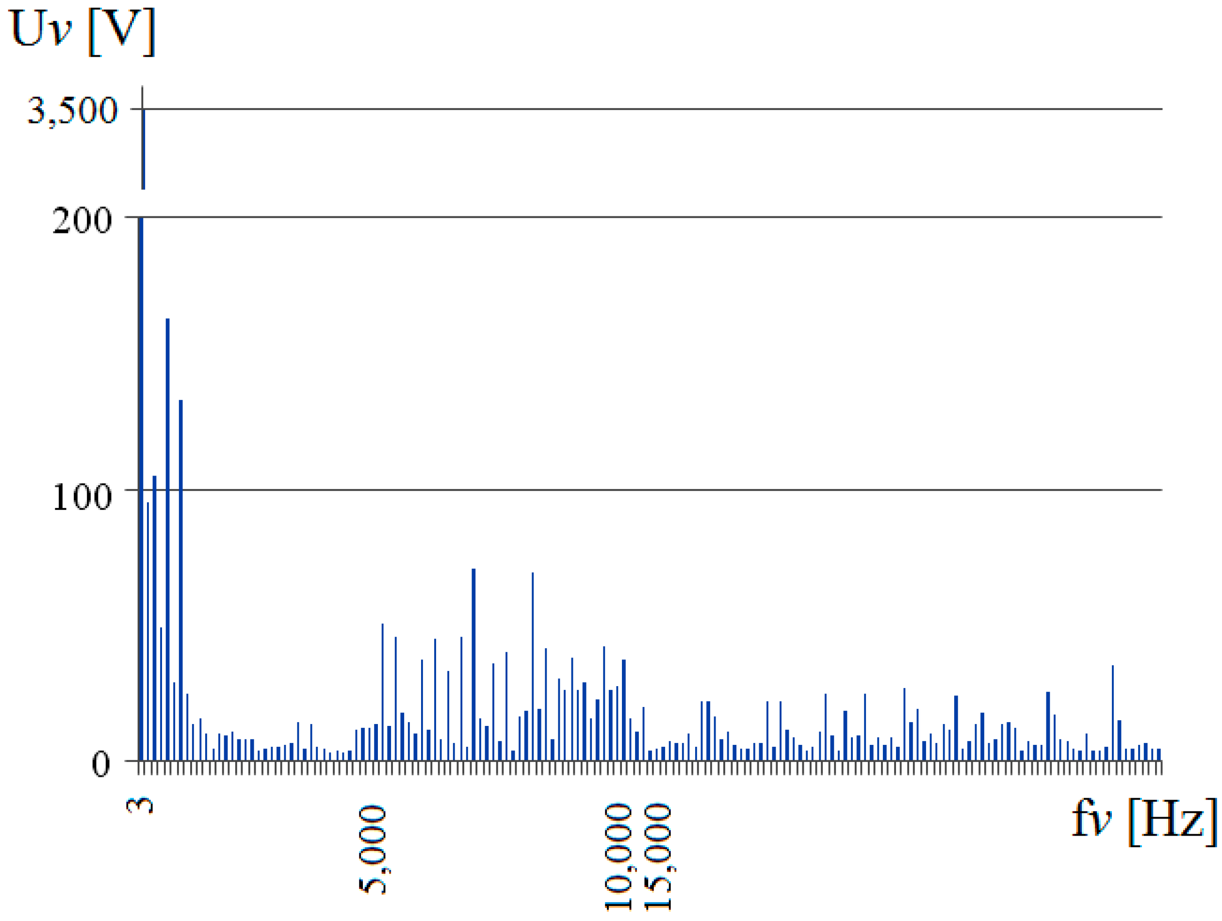
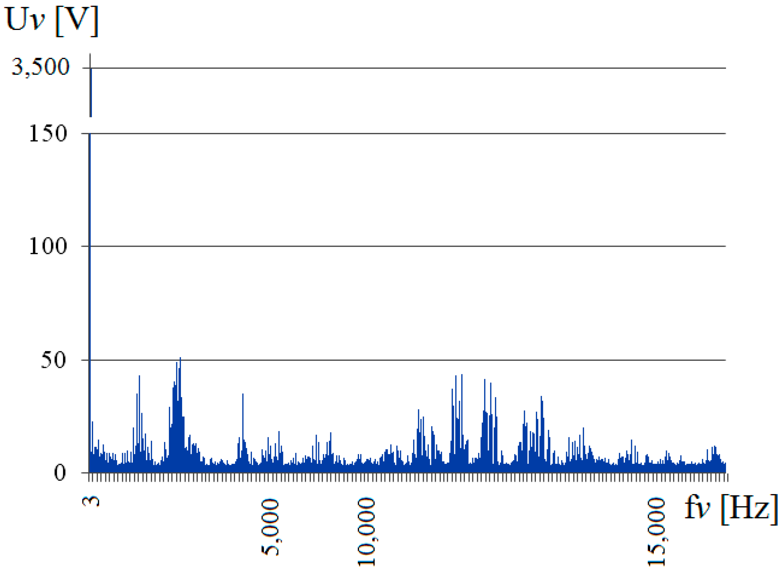
7. Spectral Analysis of the Output Voltage of the Used Frequency Converters
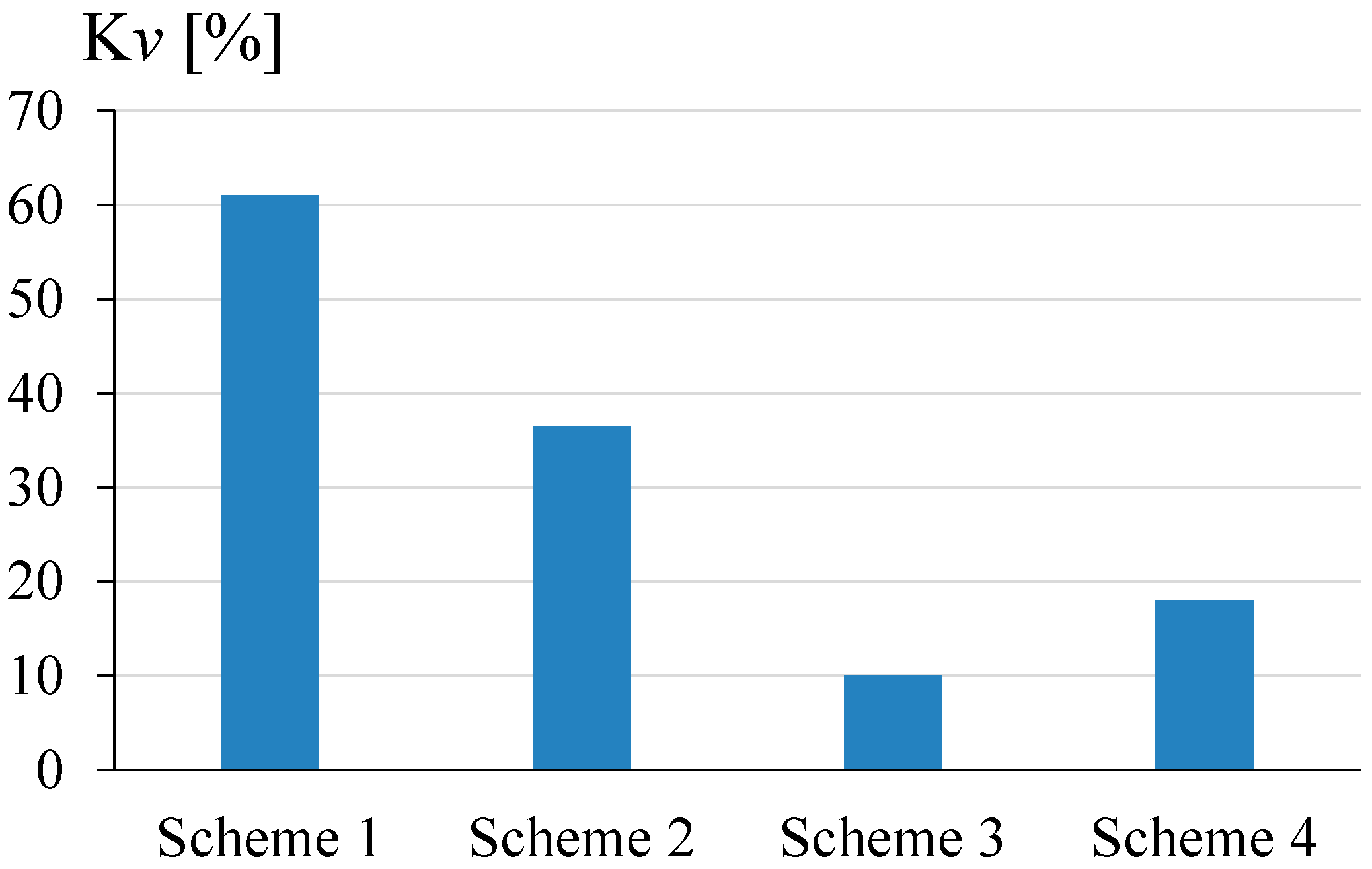
8. Comparative Analysis of the Used Frequency Converters
9. Discussion and Practical Consequences of the Results
10. Conclusions
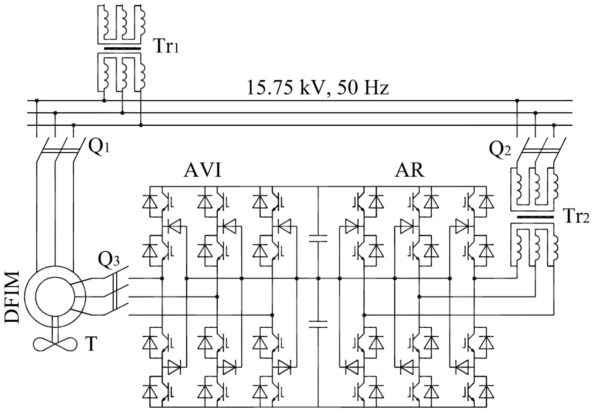
- The article presents models of four FC topologies connected to a DFIM, namely: a two-level, three-level, cascade, and multistage-multilevel FC.
- The presented modeling methodology based on interconnected sub-systems leads to rapid responses of the computer system, and thus also to more efficient use of central processing unit (CPU) time.
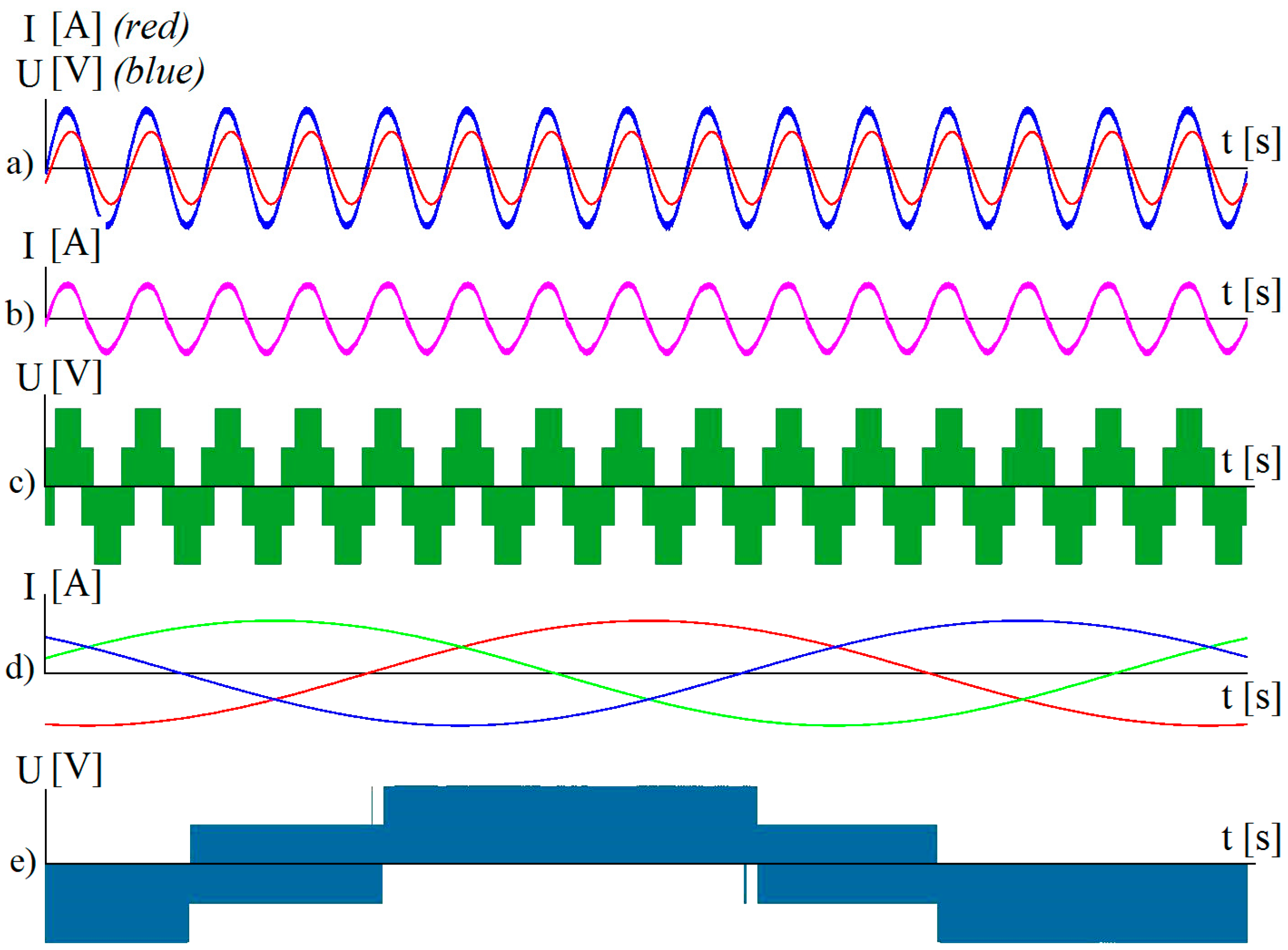
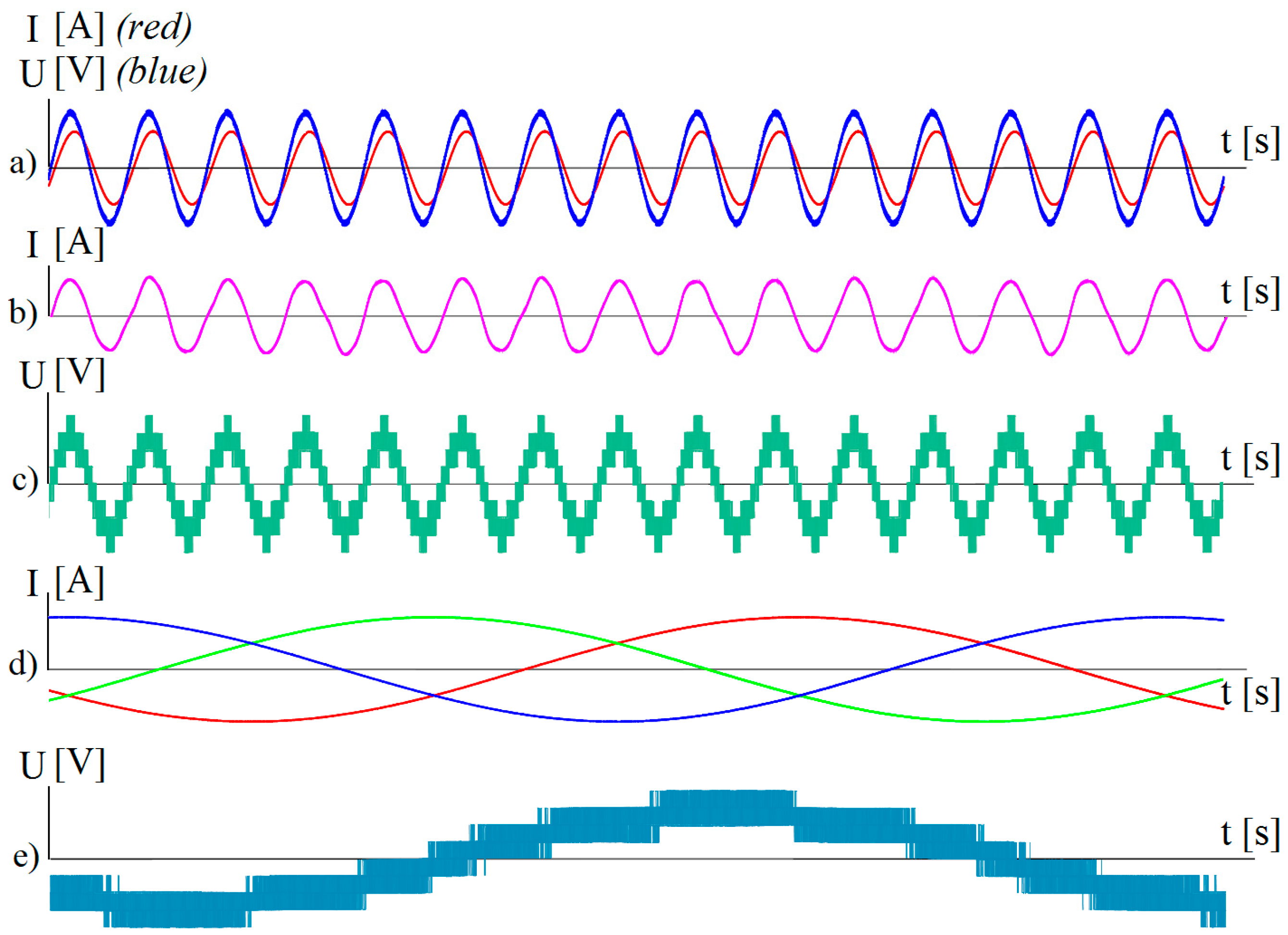
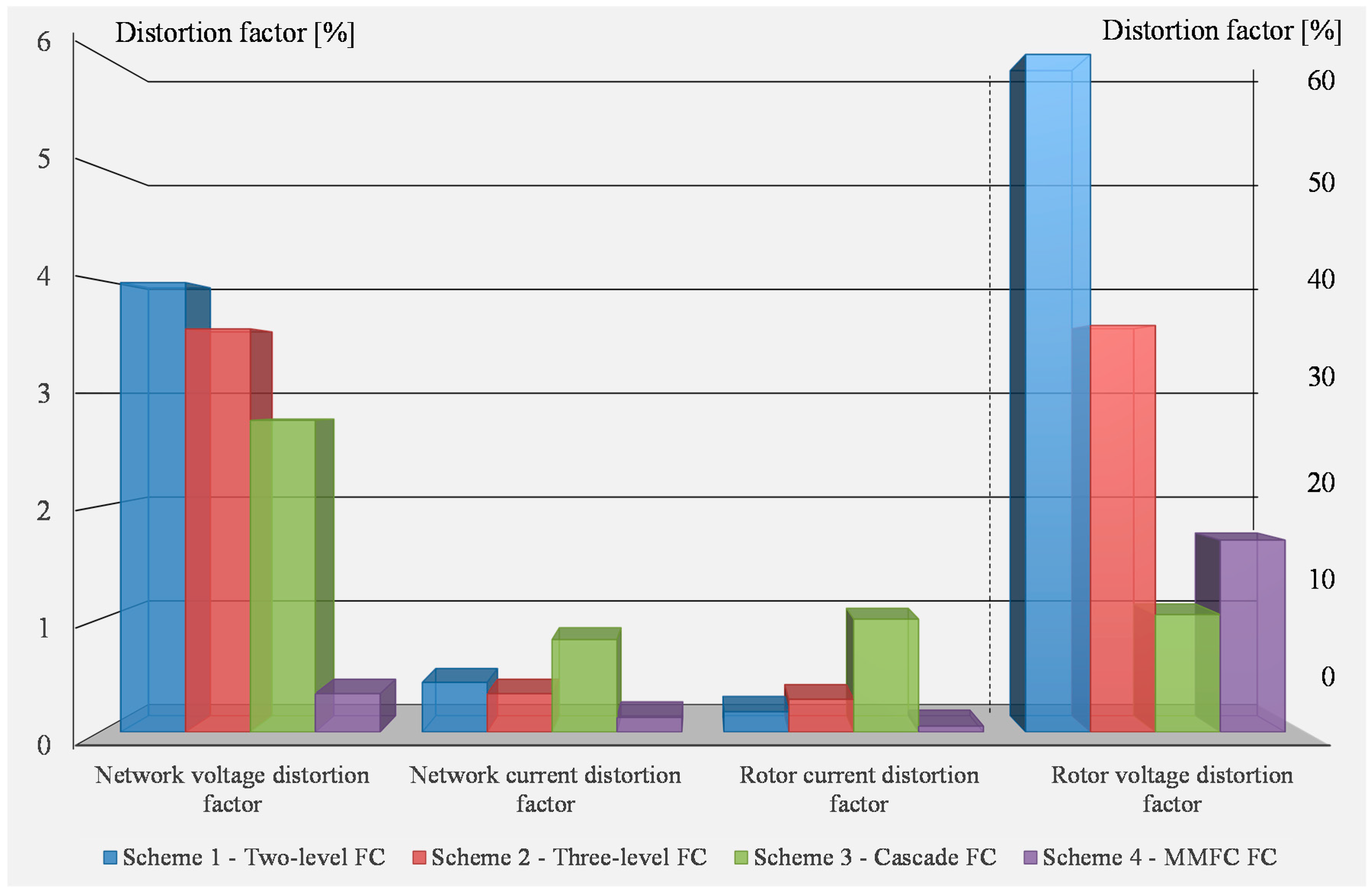
- In all of the considered variants of FCs that are considering higher harmonics in a broad spectrum, the supply voltage distortion factor of the rotor of the DFIM exceeds 10%. This demonstrates the need to analyze and take into account the effect of higher harmonics on electromagnetic processes in the PSS, DFIM energy losses, and the reliability of the system.
- A comparative analysis of PSS schemes with a doubly fed induction machine, and FCs of various types in the rotor circuit has been made.
- Taking into account the set of indicators, such as the power of semiconductor devices, capacitors energy storage, input/output voltages and currents, the use of IGBT high-speed modules etc., it is recommended to use a PSS scheme with a multistage FC in the DFIM rotor circuit.
- On the basis of complex evaluation of the parameters, the multistage FC has the most favorable values for:
- A network voltage distortion factor (9% compared to the maximum value achieved for another converter scheme);
- rotor current distortion factor (5% compared to the maximum value achieved for another converter scheme);
- power imbalance (14% compared to the maximum value achieved for another converter scheme);
- the total power of the rotor is minimal here (together with Scheme 3, the cascade FC) while maintaining the rotor speed, the active and reactive power of the power system, the active power of the stator, and the total power of the DFIM rotor at the first harmonic.
Acknowledgments
Author Contributions
Conflicts of Interest
References
- Pronin, M.; Shonin, O.; Vorontsov, A.; Gogolev, G. Features of a Drive System for Pump-storage Plant Applications based on the Use of Double-fed Induction Machine with a Multistage-multilevel Frequency Converter. In Proceedings of the 2012 15th European Conference on Power Electronics and Applications, Novi Sad, Serbia, 4–6 September 2012. [Google Scholar]
- Steimer, P.K.; Senturk, O.; Aubert, S.; Linder, S. Converter-fed Synchronous Machine for Pumped Hydro Storage Plants. In Proceeding of the 2014 IEEE Energy Conversion Congress and Exposition (ECCE), Pittsburgh, PA, USA, 14–18 September 2014; pp. 4561–4567. [Google Scholar]
- Cuesta, A.B.; Gomez-Gil, F.J.; Fraile, J.V.M.; Rodríguez, J.A.; Calvo, J.R.; Vara, J.P. Feasibility of a Simple Small Wind Turbine with Variable-Speed Regulation Made of Commercial Components. Energies 2013, 6, 3373–3391. [Google Scholar] [CrossRef]
- Singh, P.; Kaur, A. Power Control of Doubly Fed Induction Generator (DFIG) Using Back To Back Converters (PWM Technique). In Proceedings of the 2014 IEEE International Conference on Advanced Communication Control and Computing Technologies (ICACCCT), Ramanathapuram, India, 8–10 May 2014. [Google Scholar]
- Tohidy, S. Analysis and Simplified Modelling of Brushless Doubly-fed Induction Machine in Synchronous Mode of Operation. IET Electr. Power Appl. 2016, 10, 110–116. [Google Scholar] [CrossRef]
- Yuan, X.; Chai, J.; Li, Y. A Converter-Based Starting Method and Speed Control of Doubly Fed Induction Machine with Centrifugal Loads. IEEE Trans. Ind. Appl. 2011, 47, 1409–1418. [Google Scholar] [CrossRef]
- Taj, T.A.; Hasanien, H.M.; Alolah, A.I.; Muyeen, S.M. Transient Stability Improvement of a Grid-connected Wind Farm Using Doubly Fed Induction Machine Based Flywheel Energy Storage System. In Proceedings of the Power and Energy Engineering Conference (APPEEC), Hong Kong, China, 7–10 December 2014. [Google Scholar]
- Xu, Y.; Zou, Y. Spectral Analysis of an Improved Hybrid Cascade Multilevel Converter. In Proceedings of the 6th International Power Electronics and Motion Control Conference, Wuhan, China, 17–20 May 2009. [Google Scholar]
- Jiang, X.; Xiao, X.; Liu, H.; Ma, Y. The Output Spectrum Analysis of High-Power Multilevel Voltage Source Converters using Double Fourier Series. In Proceedings of the 2005 IEEE/PES Transmission & Distribution Conference & Exposition, Dalian, China, 14–18 August 2005. [Google Scholar]
- Pronin, M.; Shonin, O.; Vorontsov, A.; Gogolev, G. A Pumped Storage Power Plant with Double-Fed Induction Machine and Cascaded Frequency Conventer. In Proceedings of the 2011 14th European Conference on Power Electronics and Applications, EPE 2011, Birmingham, UK, 30 August–1 September 2011. [Google Scholar]
- Pronin, M.; Shonin, O.; Gogolev, G.; Vorontsov, A.; Nahdi, T. A Double-fed Induction Machines with a Multistage-multilevel Frequency Converter for Pumped Storage Power Plant Applications. In Proceedings of the 2011 IEEE Power Engineering and Automation Conference, PEAM 2011, Wuhan, China, 8–9 September 2011; pp. 221–225. [Google Scholar]
- Pronin, M.; Vorontsov, A.; Nahdi, T.; Kouzin, M. Analysis of Operating Modes of Asynchronised Machines for Pumped-storage Power Plants. Proc. IEEE Russ. North West Sect. 2011, 1, 51–53. [Google Scholar]
- Pronin, M.; Vorontsov, A.; Nahdi, T.; Kouzin, M. Modelling of the Multistage-multilevel Active Frequency Converter by a Method of the Interconnected Subcircuits. Proc. IEEE Russ. North West Sect. 2011, 2, 35–38. [Google Scholar]
- Nahdi, T. Modeling and Designing of Systems with Induction Machines and Active Multilevel Frequency Converters. Ph.D. Thesis, Saint Petersburg Electrotechnical University “LETI”, Saint Petersburg, Russia, 2012. [Google Scholar]
- Janning, J.; Schwery, A. Next Generation Variable Speed Pump-storage Power Stations. In Proceedings of the 2009 13th European Conference on Power Electronics and Applications, EPE’09, Barcelona, Spain, 8–10 September 2009. [Google Scholar]
- Bocquel, A.; Janning, J. Analysis of a 300 MW Variable Speed Drive for Pump-storage Plant Applications. In Proceedings of the 2005 European Conference on Power Electronics and Applications, Dresden, Germany, 11–14 September 2005. [Google Scholar]
- Bocquel, A.; Janning, J. 4 × 300 MW Variable Speed Drive for Pump-Storage Plant Application. In Proceedings of the European Conference on Power Electronics and Applications, Toulouse, France, 2–4 September 2003. [Google Scholar]
- Zhou, Y.; Bauer, P.; Ferreira, P. Operation of Grid-Connected DFIG under Unbalanced Grid Voltage Condition. IEEE Trans. Energy Convers. 2009, 24, 240–246. [Google Scholar] [CrossRef]
- Bauer, P.; Schoevaars, R. Bidirectional Switch for a Solid State Tap Changer. In Proceedings of the 2003 IEEE 34th Annual Power Electronics Specialists Conference, Acapulco, NM, USA, 15–19 June 2003; pp. 466–471. [Google Scholar]
- Rosen, M.A.; Nicola, D.A.; Bulucea, C.A.; Cismaru, D.C. Sustainability Aspects of Energy Conversion in Modern High-speed Trains with Traction Induction Motors. Sustainability 2015, 7, 3441–3459. [Google Scholar] [CrossRef]
- Skvortsov, B.; Nahdi, T.; Maga, D. Mechatronic System with a Turbo-generator of two Different Frequencies. In Proceedings of the 12th International Conference on Mechatronics, Brno, Czech Republic, 6–8 September 2017; pp. 302–310. [Google Scholar]
- De Jong, E.C.W.; Ferreira, J.A.; Bauer, P. Design Techniques for Thermal Management in Switch Mode Converters. IEEE Trans. Ind. Appl. 2006, 42, 1375–1386. [Google Scholar] [CrossRef]
- Helle, L.; Munk-Nielsen, S. Comparison of Converter Efficiency in Large Variable Speed Wind Turbines. In Proceedings of the 16th Annual IEEE Applied Power Electronics Conference and Exposition, Anaheim, CA, USA, 4–8 March 2001; pp. 628–634. [Google Scholar]
- Holmes, D.G.; Lipo, T.A. Pulse Width Modulation for Power Converters. Principles and Practice; Wiley Press: Hoboken, NJ, USA, 2003; ISBN 978-0-471-20814-3. [Google Scholar]
- Skvorcov, B.A.; Baygildina, E.I. Cascade Matrix Converter. Proc. IEEE Russ. North West Sect. 2011, 1, 33–39. [Google Scholar]


| Parameters of PSS with DFIM and FC in the Circuit of Rotor | Scheme 1 Two-Level FC | Scheme 2 Three-Level FC | Scheme 3 CASCADE FC | Scheme 4 MMFC |
|---|---|---|---|---|
| Frequency of pulse-width modulation fPWM [Hz] | 4000 | 4000 | 4000 | 4000 |
| Rotor speed of DFIM [pu] | 1.0712 | 1.0742 | 1.0742 | 1.0742 |
| Active power of the power system [MW] | 273.93 | 273.93 | 273.91 | 273.93 |
| Reactive power of the power system [MVAR] | 96.5 | 96.5 | 96.5 | 96.5 |
| Active power of the stator [MW] | 255.32 | 254.91 | 255.62 | 255.85 |
| Reactive power of the stator [MVAR] | 97.06 | 97.93 | 96.27 | 96.75 |
| Active power in the DFIM rotor circuit [MW] | 18.61 | 19.02 | 18.3 | 18.09 |
| Shaft power of DFIM [MW] | 272.33 | 271.77 | 272.67 | 272.87 |
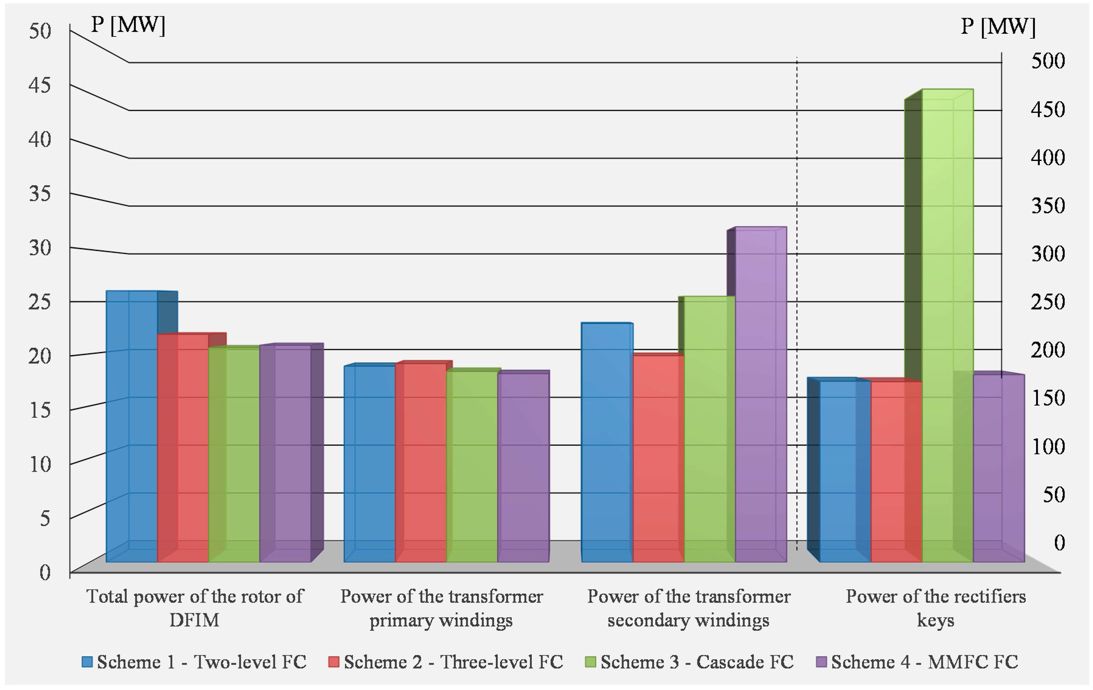
| Total power of the rotor of DFIM [MW] | 26.05 | 21.87 | 20.58 | 20.82 |
| Total power of DFIM rotor at the first harmonic [MW] | 20.55 | 20.4 | 20.47 | 20.52 |
| Power of the transformer primary windings [MW] | 18.82 | 19.06 | 18.31 | 18.09 |
| Power of the transformer secondary windings [MW] | 22.91 | 19.82 | 25.52 | 32.19 |
| Power of the rectifiers keys [MW] | 173.7 | 173.2 | 454 | 180 |
| Power of the inverters keys [MW] | 179.9 | 179.7 | 176.9 | 180 |
| Power of the isolating diodes [MW] | - | 167 | - | 135 |
| Energy of capacities (0.5∑CU2) [kJ] | 500 | 500 | 1,500 | 500 |
| Network voltage distortion factor [%] | 3.98 | 3.57 | 2.76 | 0.34 |
| Network current distortion factor [%] | 0.44 | 0.34 | 0.819 | 0.13 |
| Rotor voltage distortion factor [%] | 61 | 36 | 10.4 | 17 |
| Rotor current distortion factor [%] | 0.18 | 0.29 | 1.0 | 0.053 |
| Rectifiers modulation factor amplitude | 0.819 | 0.809 | 0.818 | 0.825 |
| Inverters modulation factor amplitude | 0.818 | 0.809 | 0.815 | 0.791 |
| Rectified voltage [V] | 10,000 | 10,000 | 820 | 10,000 |
| Rotor phase voltage at the first harmonic [V] | 3236 | 3218 | 3224 | 3224 |
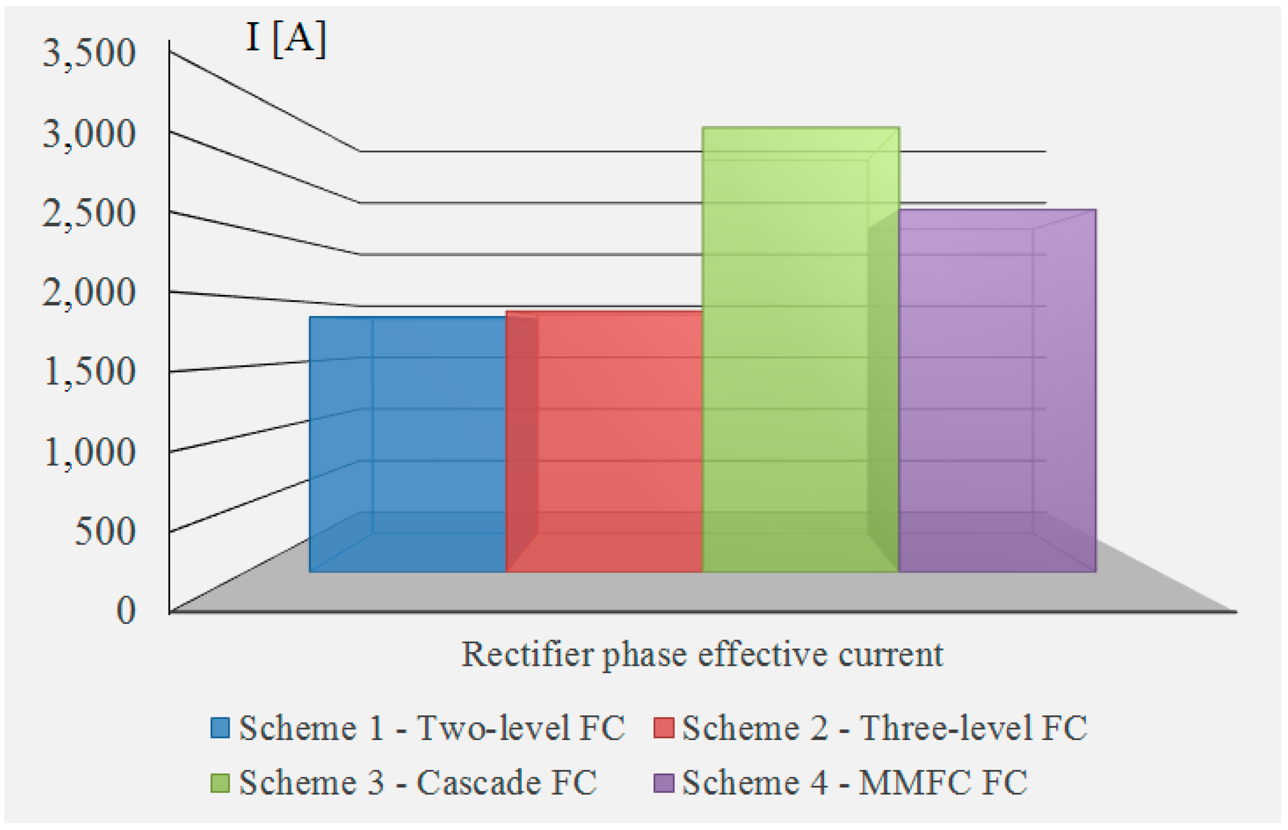
| Rectifier phase effective current [A] | 1859 | 1900 | 3237 | 2639 |
| Inverter phase effective current [A] | 2117 | 2113 | 2116 | 2121 |
| Rotor phase effective current [A] | 2117 | 2113 | 2116 | 2121 |
| Power imbalance | 0.25 | 0.43 | 0.13 | 0.06 |
© 2018 by the authors. Licensee MDPI, Basel, Switzerland. This article is an open access article distributed under the terms and conditions of the Creative Commons Attribution (CC BY) license (http://creativecommons.org/licenses/by/4.0/).
Share and Cite
Nahdi, T.; Maga, D. Comparative Study of Frequency Converters for Doubly Fed Induction Machines. Sustainability 2018, 10, 594. https://doi.org/10.3390/su10030594
Nahdi T, Maga D. Comparative Study of Frequency Converters for Doubly Fed Induction Machines. Sustainability. 2018; 10(3):594. https://doi.org/10.3390/su10030594
Chicago/Turabian StyleNahdi, Tarek, and Dusan Maga. 2018. "Comparative Study of Frequency Converters for Doubly Fed Induction Machines" Sustainability 10, no. 3: 594. https://doi.org/10.3390/su10030594
APA StyleNahdi, T., & Maga, D. (2018). Comparative Study of Frequency Converters for Doubly Fed Induction Machines. Sustainability, 10(3), 594. https://doi.org/10.3390/su10030594