Abstract
Nowadays, control systems for lighting installations are used, among other functionality, to improve energy efficiency and to set different lighting outputs of the luminaires according to punctual requirements. This allows increasing energy efficiency by adapting the installation to environmental needs. Current control systems are mainly oriented to point-2-point architectures, which in most cases, are complex and expensive. As an alternative, we present the viability analysis of a sustainable control architecture for lighting installations to improve those drawbacks. This control system uses a communication technique based on controlled power-on/off sequences in the power line of the luminaires to configure different dimming profile schedules. An implementation for LED equipment with the design of an electronic CPU based on a microcontroller is described along with a study of its configuration capability. In addition, we present the set of results obtained using this system in a real outdoor public lighting installation. Furthermore, an economic amortization study of power line communication (PLC) or radio frequency (RF) control architectures versus the results of this proposal are detailed. The analysis presents the proposal as a simple but more robust and sustainable solution compared to current point-2-point systems used with streetlights: The return on investment (ROI) period is reduced allowing all the basic functionality expected—in—field output light dimming profiles selection.
1. Introduction
One of the main activities that involve energy consumption worldwide is the lighting sector. According to the United Nations, the electricity used for lighting accounts for approximately 15% of worldwide energy consumption and over 5% of global greenhouse gas emission. Public lighting installations are an important segment of this value, consuming 8% of that total [1]. Moreover, all these outdoors luminaires have a high impact on the citizens’ perception of safety and quality of life [2]. The annual electric energy costs related to street lighting are estimated to reach between $23.9 billion and $42.5 billion by 2025 [3]. In addition, each streetlight point is responsible for generating between 330 and 1500 kg of CO2 each year according to a 2014 report by market researchers at the Northeast Group [4]. This potential has caused that many public administrations to focus their attention on improving their street lighting installation. Nowadays, these installations require, on average, between 40% of their budgets in small municipalities [5], and 12% in large European cities [6]. Several studies indicate that the savings potential that can be achieved by modernizing these facilities is above 30% if more efficient lighting technologies are installed [7]. Regulation and control systems are also required to be installed and implemented within them [8].
More than 280 million streetlights were in place in 2014 globally, and this number is expected to grow to nearly 340 million by 2025 [4]. In Europe, they have an average power of 180 W and 4300 h of annual use per point. That represents an enormous electricity spend—3715 GWh/year. Technological advances in public lighting installations, together with their intelligent use, will make it possible to reduce our overall consumption [9].
The importance given to the energy efficiency level in each new project involving lighting has led to several legislative implementations in various countries. These regulations promote the fulfilment of new energy saving requirements [10] and a rational adaptation of the levels of illumination of the streets [11]. This has caused the development of different methodologies to regulate the output light of the luminaires which use only a part of their total illumination capacity when the luminance/illuminance needs are reduced, for example, in a road with very little traffic in the early hours of the morning.
One of the first pieces of equipment to be designed to realize this diminution of the illumination intensity was developed in the 1980s (US patent 4189664A). The working principles developed were based, first, on a constant reduction of the voltage applied in the power transmission lines and, second, in periodic micro-cuts on the power signal at the same phase segment. These devices worked directly and continuously over the parameters of the power network and, consequently, were expensive and delicate. They required an adequate process of maintenance and continuous supervision over time. These two problems have been minimized with the application of electronic circuits that eliminate the needs of large power transformations or continuous commutation [12].
Nowadays the lighting sector is currently undergoing a digitization process that is changing all the fundamentals of the industry. New light-emitting technologies allow more efficient luminaires and a significant improvement in their management, regulation, and supervision capability [13].
This process began with the development of electronic ballasts. They replaced the electromagnetic technology required to limit the current and ignite conventional discharge lamps (fluorescent, CFLs, metal halides or high and low-pressure sodium bulbs) enhancing the energy efficiency of these luminaires [14]. In addition, it has added another series of important intrinsic advantages of electronics. For example, the ability to control points of light in both autonomous (programmed) way and through external commands sent by a central control unit using different types of communication interfaces [15].
New electronic drivers (for LED luminaires) take advantage of two basic possibilities offered by the digital processors: digital communication ports and (as in our case) the ability to count stretches of time between events (such as the turning on and off processes of the grid) and act based on these measures [16].
Control Systems of Outdoor Lighting Installations
Research efforts to interconnect a control unit with the luminaires in an installation have focused on the development of electronic interfaces or gateways along with hardware layers (data buses). This permit to send and receive information acts within a communication protocol.
The basic objective is to regulate, dynamically, the luminous flux of the luminaires and adapt the luminance/illuminance obtained to the specific needs of the roads. This is a proposal that is enabled and enhanced by different current energy-saving technologies [13,17] and supported by sustainable national regulations. For example, one system may work using dimming evolution profiles as specified, for example, by the EN 13201-1:2014 standard. This indicates that significant variation of parameters values can be applied at different periods of the night reducing lighting levels and, thereby, energy consumption. These reductions can be applied in the periods when a lower lighting class is allowed as indicated in its lighting situation tables.
Wojnicki et al. [6] and Jagerbrand [11] indicated that the use of this methodology leads to savings between 6% and 50% compared to the electrical consumption of an equivalent installation without regulation systems.
Three communication systems have imposed themselves in the market for lighting equipment: wired buses specific digital communications (i.e., DALI), power line communication (PLC) transceivers, and wireless communications systems in the radio frequency (RF) range. They not only provoke the dimming process in the luminaries but also take care of supervision and information harvesting tasks as their exact consumption parameters or operating alarms [10]. Specifically:
- Wired digital buses are generalized in indoor lighting installations, and there are available patented solutions and commercial standards: DMX, DALI, KNX, or LonWorks. Their physical installation outdoors presents several drawbacks: They cannot cover large distances; the installation of additional wiring is expensive and complicated in many cases, and they are sensitive to Electro Magnetic Interferences (EMIs) and surge currents. Because of these limitations, their use in street lighting is limited [18] beyond special installations like in tunnels [19],
- PLC systems eliminate the need to include additional wiring since data and power share the same wires as the transportation channel [5]. Thus, they require electronic adapters in each piece of equipment connected to the power network to send and receive packets with digital information modulated over the power sinusoidal base signal that drives voltages over 100 VAC. Despite the reduction of requirements in the wiring structure, PLC operating networks occasionally present drops caused by the appearance of electric noise that can last up to several minutes, and there may be high latency or communication failures due to carrier signal attenuation [16]. Examples of commercial solutions: inteliLIGHT (by Flash Group), Minos System (by UMPI), eSMART (by ELT), or CIRLAMP (by Circuitor), and
- RF systems include transceiver devices attached to the lighting poles that create a communication network using a mesh topology where the data packets travel from/towards a central system to any addressed light point jumping through the communication modules of the luminaires physically located between these two end-points [15,20]. Depending on the frequency used (2.4 GHz—ZIGBEE range—or other lower frequencies’ open bands, such as 433 MHz or 866 MHz—in Europe) different bandwidths can be obtained, in an inverse relationship with the point-2-point transmission distance that can be reached [21]. Examples of commercial solutions: LightGrid (by GE Lighting), City Touch (by Philips), NB-IoT (by Huawei), or Owlet (by Schreder).
All these architectures analyzed allow bidirectional communications that optimize their functionality. However, they require:
- Complex specific hardware modules that act as communication transceivers adapting the signals to the physical layer and the data transmission protocols [22], and
- Remote monitoring and control systems that include, at least, a back-end server to run control software and multiple decentralized mid-term controllers in the electric panels of the lighting installation [12].
All this equipment implies a significant increase in the final cost of the installation (e.g., adapting the electric panels for large signal adaptation devices as in PLC architectures). Although these public lighting management systems contribute to the reduction of energy consumption, the global installation costs considering new LED luminaires (lighting equipment + control system) have return on investment (ROI) periods of, at least, 6.5 years for replacing grid-connected luminaires [23] or 5 years when using solar-powered luminaires [12].
However, and as far as we have investigated, we have not been able to identify any study that dissects the economic viability of a control system in lighting installation as an individual element. The papers available in the literature are mainly based on full-duplex digital transmission with no direct comparison over our technical development and, moreover, they do not declare their specific cost making it difficult to evaluate independently their ROI or any other economic indicator that measures the sustainability of the investment required. For example, Sjöberg et al. [24] study reflects the energy cost and the saving of a street lighting smart control system installed in the Uppsala municipality but omitting, specifically, the armature cost of this system, and Marino et al. [25] and Farkas et al. [26] presented an energy consumption reduction analysis of different case-of-study of outdoor lighting control systems but without any cost evaluation of these electronic equipment.
If we just consider the costs of the communication architecture, there are two basic components: hardware (communication transceiver and control units for the luminaires, communications switchboards, consumption meters, power interfaces, modems, web servers…) and recurring costs (M2M communications, web hosting and software configuration, maintenance and updates). Based on the information given by several of the previous manufacturers listed, assuming the installation of 50 luminaires and one electric panel frame, the investment for the RF or PLC hardware is, approx., 60.00 €/luminaire (considering all the hardware requirements) and 180.00 €/electric panel and year. Many of these installations are paid with subsidies that cover the hardware installation costs but neglect the recurring costs. A bad evaluation of this item by the public administrations or not planning a specific budget to pay recurring costs may leave this installation out of service without the generation of the economic and technical benefit expected.
Within an adequate scenario, significant savings come from the reduction of electrical consumption and through the prolongation of the lifetime of the luminaire. However, the ROI calculated reaches a value of 13.3 years. See Table 1.

Table 1.
Calculation of the return on investment (ROI) of an average radio frequency (RF) or power line communication (PLC) point-2-point street lighting communication architecture installation. All the calculations are done considering 4300 working hours per year.
These additional costs and large ROIs led to the development of self-regulating programmed drivers to obtain equivalent energy savings. They are characterized by operating autonomously following an adaptive proportional dimming profile loaded in the manufacturing process of the luminaire. These are drivers more complicated and expensive than regular models, but the overall solution is more affordable, and the investment required more sustainable. Thus, measuring time segments has become a standard in the market of drivers and controllers for LED luminaires [27].
This solution encounters a major drawback. Only one dimming profile configures a rigid structure that hardly offers an optimal function for all the different lengths of the night in each season. Only slight regulations can be made by reconfiguring the setting of the astronomical timer switches or the reference levels of the crepuscular sensors that are used to reduce the use of the installation during the length of the night. Therefore, it is difficult to find an optimized single profile adequate for all seasons or for special events, such as festivities at which maximum lighting is required all night. An alternative to managing different configuration of programs in a lighting installation based on power line pulses commutation is studied here. This solution supports increased flexibility with a reduced ROI period compare to the one detailed for point-2-point architectures.
2. Control Architecture Proposal
A simple communication mechanism is analyzed to allow making changes in the configuration of a street lighting installation. The aim is to permit the use of different profiles of light regulation as required. Thus, the savings and energy efficiency of this installation can be adjusted for different requirements. Figure 1 shows different working dimming routines that fulfill the adjustment to the night length on different seasons of the year or special events that may require different adaptive working modes. Each ignition point is established by an automated system to match precisely the nightfall. The periods of maximum light requirements at the beginning (dusk) and end (dawn) of the night are indicated with a different background than the mid-night segment where dimming is desired.
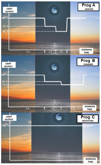
Figure 1.
Operation diagram for different times of the year or different event may require different working modes. Dimming modes, when used, must comply with the EN 13201-1 requirements.
The basic minimum infrastructure in all street lighting installations, as presented in Figure 2, is the switching capacity (OFF/ON) of the power lines through contactors installed in their electrical panels. This, together with a non-programable dimmable driver (i.e., standard 0–10 V) and one microcontroller including timer peripherals, has the ability to generate pulse width modulation (PWM) control signals and, with certain digital memory capacity for data storage, it is enough to fulfill our requirements to generate a power–pulse configurable lighting installation. Thus, it is possible to use the ability to count time not only to establish different working dimming profiles but also to be able to interpret small power on cycles as packages of information transmitted through the power line.
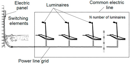
Figure 2.
Basic diagram for a set of installed luminaires.
In this way, an “OFF/ON/OFF” power cycle in a line of luminaires for a short, but controlled, time, allows sending information to these devices provided that the emitter (responsible for the control) and the receiver (the luminaires) have a common approach established that univocally relates the duration of the pulse with specific information.
Therefore, this is a basic unidirectional communications system that does not include any additional hardware from the minimum legal electrical installation for public lighting and a basic electronic CPU. The basic information sent to the lamps may be used to select a certain lighting sequence from a preprogrammed set in a permanent memory that must be used from now on in all its working cycles until it is changed again, at will, by this same mechanism. In this case, the element that carries the information is not an RF packet or a modulated over the sinusoidal of the power signal, but the time gap of a dedicated active ignition cycle that choose an active programming from a set previously incorporated in the luminaires. These programs are designed in the planning stage of the installation and later stored within the non-volatile memory of each electronic control unit for the luminaires during its manufacturing process before its integration on their final equipment.
This overall system requires a minimum quantity of components, and all of them have large lifetime expectation (a practical implementation will be described in Section 3: Materials and Methods) and takes advantage of the mandatory commutation elements of this type of lighting installation, such as contactors, installed in the electrical panels.
The switching process of the power line of the luminaires can be done either manually or through a control unit installed in the electric panel. This control unit would have the capacity to activate the power contactors of each power lines controlled by this unit. These control equipment can be controlled remotely by a software application in the same way as in any point-2-point architectures.
3. Materials and Methods
Figure 3 shows the schematic of the proposed reference lighting installation. The set of required modules include:
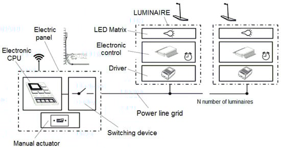
Figure 3.
Block diagram of the relevant elements to install for the proposed configuration model.
- An electric control panel with commutation elements for one or several power supply lines. They allow turning on and off the luminaires in a precise controlled way through a tele controlled CPU unit or by an operator who activates and deactivates the switches manually, and
- A set of connected luminaires. Each of them must integrate an electronic control unit that has to decode properly the stretches of time of the power cycles and takes control over the dimming port of the non-programable driver of the luminaire. Our test implementation includes:
- ○
- One very low power microcontroller (MSP430F2001/Texas Instruments).
- ○
- One operational amplifier (LM258/Texas Instruments) with a PWM input filtered with a RC circuit to generate an equivalent 0–3.3 VDC analog signal on the positive input and an output feedback through the negative input to generate a 3:1 output gain of 3:1 of the positive input.
- ○
- Two linear voltage regulator (L78L12AB and L78L33AB) to obtain a 12.0 VDC and a 3.3 VDC power signals from the output of the driver of the luminaire
- ○
- Several RC components (ceramic capacitor and thin film resistors) to generate the reset, input and feedback signal circuits required.
The complete system is developed with 13 components where 9 of them are RC components as detailed in Figure 4. Electrolytic capacitors or any other critically temperature sensible item are not needed. In this sense, all the elements listed are less critical than several necessary elements to manufacture the driver of the luminaire.
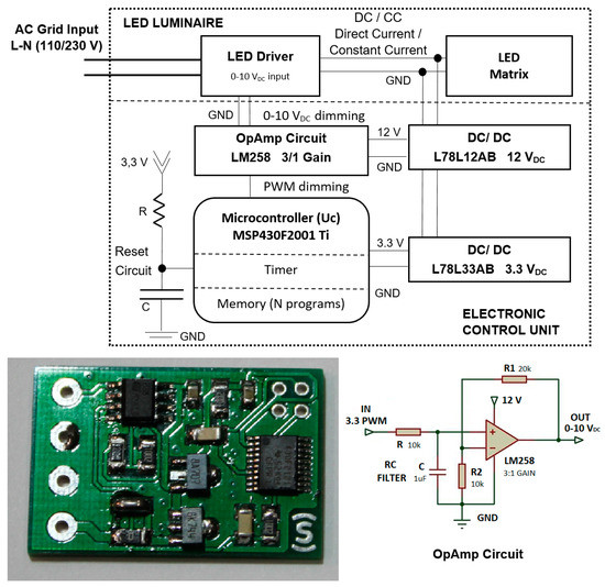
Figure 4.
Electronic schematic of the regulation and control system installed in each luminaire and proposal of implementation.
This electronic circuit can be attached to any dimmable LED, downstream on the Direct Current (DC) side of the luminaire, a driver using 4 wires: Two inputs for the DC power output of the driver {The positive voltage supply (VDC) + ground (GND)} and 2 outputs for the dimming control {0–10 VDC + GND}. The two GND lines are redundant as they drive to the same voltage point. With this implementation, the control unit is covered by all the protections of the power supply (over current, over voltages, over temperatures, short circuit…) or the surge voltage protection device of the luminaire, which cover all the emergency situations that may face a luminaire in outdoor working conditions.
In a basic control implementation, different time-lapse segments can be established so that each of them codifies a different diming profile. If the AC input power pulse is cut off within one of them, the system will assign the corresponding state as the new visualization program for the following working cycles. This profile is kept until another program is selected using this same protocol.
The system has been tested in a real installation deployed in an electrical panel of a street lighting installation in a small municipality (population: 2900 inhabitants) in south Spain. It serves a segment of 6 streets on the outskirts of the village with 3 output lines with a total of 470 m (line 1: 145 m, line 2: 160 m, and line 3: 165 m) 6 mm2 section distribution cable. Four units of 80 W street lighting LED luminaires and 5 luminaires of similar characteristics but with 35 W are installed in each of these power lines. All of them are identical within their own power range and have installed a basic 0–10 V driver and the electric control circuit described. Each line has its own contactor for switching control and an ABB B23 digital power meter with 3 phases of Class 1 Series B precision installed as shown in Figure 7.
Design Difficulties and Solution Proposals
The time length of the “OFF-ON-OFF” power transition carries the information to be transmitted to all the luminaries of the same electric line. This length cannot be either too short, so that is not possible to mistake it with a glitch or a faulty start, or too long, generating a programming process inconveniently slow.
To solve the first requirement, we establish that the minimum recognizable pulse to transmit information cannot be shorter than 10 s. For the second requisite, thanks to the fast action of the electric contactors which can disconnect a power line in few milliseconds, it is desirable that the range of lengths of the time segments used to codify data are established as short as possible. However, there are technical conditions that limit the precision and speed capability of this communication system if the electronic control unit is powered with the output of the luminaire´s driver (which is the simplest alternative). This situation conditions the minimum length of the time segments so that any luminaire, regardless of its driver model, can work correctly in any situation within a standard implementation of the control system.
The stabilization capacitors of the DC output of LED drivers result in the complete elimination of the DC/CC output voltage being not instantaneous as the AC input is switched off. The DC power signal decreases in an exponential form, and it takes time before it goes below a value that the processor is able to detect (generating a reset interruption with a power input below 1 VDC) without using any additional complex, inefficient or expensive hardware. This discharge time is significantly long and is not constant in different models of the drivers; this stretch of time varies from a few seconds to close to a period of 20 s. The 2 main variables on which this time depends are the nominal power of the driver and the load at which it is operating at shutdown. To establish adequate minimum time segment ranges, we have tested and analyzed the behavior of 11 commercial drivers with dimming capability (0–10 VDC) by 3 major manufacturers with different power outputs and in three working modes: 100%, 75%, and 50% of their nominal load. LED matrixes adequate to each desired output current and power consumption with aluminum heatsinks were connected to the different drivers tested and then powered with 230 VAC. After 5 min, they were dimmed to each testing state required and left for another 5 min to reach stable load conditions. Afterwards, they were turned off and the discharger ramps were recorded using a Tektronix TDS 1002 Oscilloscope. All the measurements obtained are detailed in Table 2 and the switching off discharge dynamic of 2 of them are presented in Figure 5.
Table 2.
Discharge time of the direct charge (DC) output below 1 VDC of several LED drivers in different working conditions.

Figure 5.
Discharge curves of the ELG-150-24B (left) and ELG-75-24B (right) by Meanwell both working at their nominal power.
From the results obtained we can calculate the difference between the minimum and the maximum discharge time measured, and establish that a safe stretch of time of at least 20 s for each range of time used to detect one same data is required. Any power commutation within this range would allow programming the luminaires connected on that bus with the same arranged profile. Based on this decision, in the case where a system is required to distinguish between 5 different programs—identified with letters from ‘A’ to ‘E’ in Figure 6—incremental sections of 20 s must be assigned to codify each of them. It is also necessary to leave an initial stretch of 10 s to avoid glitches. Thus, if the programming ignition pulse on a lane of luminaires oscillates between 10 s and 30 s, the ‘A’ program will be activated in all of them. If the pulse last between 30 s and 50 s, the ‘B’ program will be memorized. For a time between 50 s and 70 s the ‘C’ program is requested and so on until the power pulse lasts more than 110 s. In this case, no programming will be considered as it is assumed as a normal working cycle along a complete night. This same working mode will be used in all the following cycles until other programming process is detected.
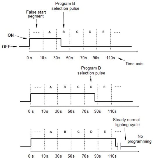
Figure 6.
Switching time diagram to configure the regulation program to be used by the luminaires on the next working cycles.
According to this sequence, to codify a programming pulse that is recognizable by all types of drivers, the selection of profile ‘A’ requires of a standardized pulse of 10 s; profile ‘B’ needs one of 30 s; profile ‘C’ needs one of 50 s; and so on. Thus, all the discharge curves will lie within the same desired switch-off detection segment.
These configuration pulses can be applied on the system any time. It is advisable to choose a moment when it is less annoying or strange for citizens in the surrounding of the luminaries. For example, outdoor public lighting can be programmed during the day so that it goes completely unnoticed by pedestrians.
The program currently configured in the luminaires can be made noticeable by technicians with a visual feedback system. After the turn-on ignition process, a dynamic dimming power-on sequence in the form of a number of flashes or light output fluctuations can visually indicate which lighting control profile is loaded and, therefore, used in that working cycle.
4. Results and Discussion
The field test installation was maintained for two months, periodically performing various program changes in each of the lines to test functionality, reliability, and endurance. Figure 7 also presents the recording of the power consumption during a winter night where lines 1 and 2 follow a program that has 5 dimming segments adapted to the indicated season (30 min initial segment at 75% of power followed by 4.5 h at 100%, 2 h at 75%, 4.5 h at 50%, and the rest of the time until shutdown at 75%. Line 3 was loaded with a profile that keeps the light output at nominal value (100%) all night long. No incidence of use was noticed during the time that the test facility was operational.
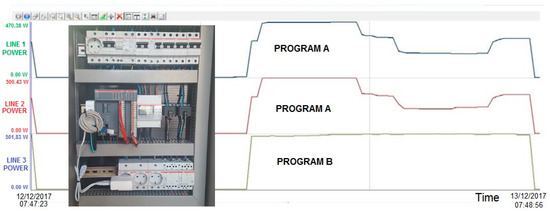
Figure 7.
Schematic of operative work in electrical control panel for different schedules.
The commercialization price of this architecture considers:
- The cost of the control unit (electronic components, PCB and assembly costs, and cabling and packaging for a 1.000 units production batch),
- A proportional part of the equipment to be installed in the electric panels (consumption meters, and communications switchboard) and a web server,
- Indirect cost, and
- A company benefit of 40%.
Under these circumstances, the selling price of the system can be established below 25.00 €/luminaire and larger production plans can reduce this value. A significant cost-related advantage of the proposed system is the reduction of the recurring costs required. This happens because the amount of communication data to run a few changes of profiles through the year is much lower compared to the requirements of a point-2-point control and supervision scheme, and any possible software has fewer maintenance requirements. Because of this, recurring costs can be assessed as 5.00 €/month × Electric Panel. This second type of cost reduction has a greater saving capability than the one obtained with the hardware. For a 20-year lifetime expectation, the hardware cost reduction would be of 25.00 €/luminaire, while the value related to recurring costs would be of ([180.00 €/year]/50 luminaires − [60.00€/year]/50 luminaires) × 20 years = 48.00 €/luminaire.
To cover a worst-case scenario we study the ROI period of this solution in Table 3, considering a 30.00 € unitary price configured in the same conditions than reference installation used in Table 1 for RF or PLC solutions. In both cases, RF/PLC control units or the proposed circuits, the luminaires connect themselves to the driver through a 0–10 V dimming port. The ROI period is reduced from 13.3 years to 4.34 years (approx. three times lower and this difference can be improved with larger production batches to reduce costs). The new period obtained is in the same range as the one given by a conventional lighting technology to LED point-by-point renewal inversions making, both inversions equally profitable.
Table 3.
Calculation of the ROI of the street lighting power-commutation communication architecture.
Finally, we should note that the architecture of this system allows its installation on a stand-alone basis, without any type of control, rather than the electronic CPUs of the luminaries. The configuration power pulses can be executed manually with a clock or a chronometer by a human operator who has moved to the electrical panel for a season profile change or a special actuation. In this case, the functionality is kept under no telematic control, reducing the hardware cost significantly and eliminating the recurring invoice.
5. Conclusions
Public Administrations are making large investments to renew their outdoor lighting installations to improve their performance and, to a greater extent, to obtain significant energy savings. Thus, they seek to optimize the economic and social sustainability of the new implementations and promote wellbeing in the places where people live while conserving, as much as possible, the economic resources available. Changing old luminaires with new points of light based on energy efficient technologies, such as LEDs, is the most extended ongoing action proposed. However, the implementation of control systems would help to achieve greater energy savings and to improve managing capability and regulation functionality.
The most common control architectures found in the market require a point-2-point data-transmission system. They offer large control possibilities, but they are also complex and expensive, increasing the total economic cost of the project significantly, including its implementation, with large ROI that reduce the profitability of the investment (approx. 13.3 years). Consequently, they are not a sustainable investment option. Low budget projects which generate significant social and environmental impacts and with an adequate financial return are often prioritized. Only significant installations with large social relevance are suitable to be adapted with such type of systems, where improved functionality stands over energy or economically sustainable criterions. On the other hand, in this paper, we have presented an architecture that offers the possibility to generate and modify the behavior of a lighting installation, with different dimming regulation profiles selectable among several pre-loaded options, without a specific communication bus or physical communication layer. This solution offers a flexible solution that allows significant dimming profile changes to adapt the installation to seasonal changes, time shifts, and festivities or special social events; demands that cannot be adequately treated with drivers with predefined dimming profiles or constant lighting output (CLO) systems.
This architecture requires only of a simple digital electronic circuit prepared to be embedded in any type of luminaire with a dimmable driver—connected through the control input (i.e., 0–10 VDC) —independently of its nominal power, energy efficiency, light source, or photometric diagram. This low-cost solution allows its implementation without increasing the ROI of the lighting installation renewal investment (approx. 4.3 years), and is suitable for the urban or rural sector, where no specific point-2-point control is required (in most cases).
An implementation proposal has been here presented, indicating the technical limitations found to optimize its performance. This is a very robust solution as it does not require any electrolytic capacitor or any other limited lifetime component. A field installation has been mounted and analyzed, showing the power saving achieved with this technique along with the flexibility to adapt the dimming profile of this installation to any punctual requirement.
Author Contributions
A.G.-C. and A.O.-M. conceived the electronic design and realized the laboratory experiments; M.J.H.-O. performed in-field experiments and analyzed these data; J.R.A.-D. contributed to materials, tools and analysis methodology; A.O.-M. and A.G.-C. wrote the paper.
Funding
This research was funded by the Solitec Foundation, grant number [FS18-003AB].
Acknowledgments
This investigation has been supported by the Solitec Foundation (Málaga, Spain) that has given funds and equipment to develop this investigation and to support an open access publication of the results.
Conflicts of Interest
The authors declare no conflict of interest.
References
- United Nations Environment Programme. Accelerating the Global Adoption of Energy-Efficient Lighting; United for Efficiency (U4E) Policy Guide Series: Paris, France, 2017. [Google Scholar]
- Beccali, M.; LoBrano, V.; Bonomolo, M.; Cicero, P.; Corvisieri, G.; Caruso, M.; Gamberale, F. A Multifunctional Public Lighting Infrastructure, Design and Experimental Test. J. Sustain. Dev. Energy Water Environ. Syst. 2017, 5, 608–625. [Google Scholar] [CrossRef]
- Sedziwy, A.; Kotulski, L. Towards Highly Energy-Efficient Roadway Lighting. Energies 2016, 9, 263. [Google Scholar] [CrossRef]
- Northeast Group. Global LED and Smart Street Lighting: Market Forecast (2015–2025); Northeast Group: Washington, DC, USA, 2015; Volume 2. [Google Scholar]
- Ozadowicz, A.; Grela, J. Energy saving in the street lighting control system-a new approach based on the EN-15232 standard. Energy Effic. 2017, 10, 563–576. [Google Scholar] [CrossRef]
- Wojnicki, I.; Ernst, S.; Kotulski, L. Economic Impact of Intelligent Dynamic Control in Urban Outdoor Lighting. Energies 2016, 9, 314. [Google Scholar] [CrossRef]
- Valentová, M.; Quicheron, M.; Bertoldi, P. LED projects and economic test cases in Europe. Int. J. Green Energy 2015, 12, 843–851. [Google Scholar] [CrossRef]
- Beccali, M.; Bonomolo, M.; Ciulla, G.; Galatioto, A.; Lo Brano, V. Improvement of Energy Efficiency and Quality of Street Lighting in South Italy as an Action of Sustainable Energy Action Plans, The Case Study of Comiso (RG). Energy J. 2015, 92, 394–408. [Google Scholar] [CrossRef]
- De Paz, J.F.; Bajo, J.; Rodríguez, S.; Villarrubia, G.; Corchado, J.M. Intelligent system for lighting control in smart cities. Energy 2016, 372, 241–255. [Google Scholar] [CrossRef]
- Mahoor, M.; Salmasi, F.R.; Najafabadi, T.A. A Hierarchical Smart Street Lighting System with Brute-Force Energy Optimization. IEEE Sens. J. 2017, 17, 2871–2879. [Google Scholar] [CrossRef]
- Jagerbrand, A.K. LED (Light-Emitting Diode) Road Lighting in Practice: An Evaluation of Compliance with Regulations and Improvements for Further Energy Savings. Energies 2016, 9, 357. [Google Scholar] [CrossRef]
- Kovacs, A.; Batai, R.; Csaji, B.C.; Dudas, P.; Hay, B.; Pedone, G.; Revesz, T.; Vancza, J. Intelligent control for energy-positive street lighting. Energy J. 2016, 114, 40–51. [Google Scholar] [CrossRef]
- Gutierrez-Escolar, A.; Castillo-Martinez, A.; Gomez-Pulido, J.M.; Gutierrez-Martinez, J.M.; Stapic, Z.; Medina-Merodio, J.A. A Study to Improve the Quality of Street Lighting in Spain. Energies 2015, 8, 976–994. [Google Scholar] [CrossRef]
- Montoya, F.G.; Peña-García, A.; Juaidi, A.; Manzano-Agugliaro, F. Indoor Lighting Techniques: An overview of evolution and new trends for energy saving. Energy Build. 2017, 140, 50–60. [Google Scholar] [CrossRef]
- Shahidehpour, M.; Bartucci, C.; Patel, N.; Hulsebosch, T.; Burgess, P.; Buch, N. Streetlights are getting smarter: Integrating an intelligent communications and control system to the current infrastructure. IEEE Power Energy Mag. 2015, 13, 67–80. [Google Scholar] [CrossRef]
- Kaleem, Z.; Yoon, T.M.; Lee, C. Energy Efficient Outdoor Light Monitoring and Control Architecture Using Embedded System. IEEE Embed. Syst. Lett. 2016, 38, 18–21. [Google Scholar] [CrossRef]
- Liang, G.Z.; Xu, X.Y. Residential Area Streetlight Intelligent Monitoring Management System Based on ZigBee and GPRS. In Proceedings of the International Conference on Materials Science, Energy Technology, Power Engineering, Hangzhou, China, 15–16 April 2017. [Google Scholar]
- Ożadowicz, A.; Jakub, G. The street lighting control system application and case study. In Proceedings of the IEEE International Conference on Event-Based Control, Communication, and Signal Processing, Krakow, Poland, 17–19 June 2015. [Google Scholar]
- Qin, L.; Dong, L.L.; Xu, WH.; Zhang, L.D.; Leon, A.S. An Intelligent Luminance Control Method for Tunnel Lighting Based on Traffic Volume. Sustainability 2017, 9, 2208. [Google Scholar] [CrossRef]
- Costa da Fonseca, C.; Palucci-Pantoni, R.; Brandão, D. Public street lighting remote operation and supervision system. Comput. Stand. Interfaces 2015, 38, 25–34. [Google Scholar] [CrossRef]
- Raza, U.; Kulkarni, P.; Sooriyabandara, M. Low power wide area networks: An overview. IEEE Commun. Surv. Tutor. 2017, 19, 855–873. [Google Scholar] [CrossRef]
- Daely, P.T.; Bayu, S.G.; Kim, J.W.; Jang, Y.; Kim, D.P.; Shin, S.Y. Wireless LED Streetlight Platform with Weather Monitoring and Color Temperature Control System. J. Korean Inst. Commun. Inf. Sci. 2017, 42, 1038–1046. [Google Scholar] [CrossRef]
- Perko, Z.; Topić, D.; Perko, J. Standardized system for monitoring and control of public lighting networks. In Proceedings of the International Conference on Smart Systems and Technologies, Osijek, Croatia, 18–20 October 2017. [Google Scholar]
- Sjöberg, I.; Gidén Hember, A.; Wallerström, C. Smart Street Lighting: The Advantages of LED Street Lighting and a Smart Control System in Uppsala Municipality; Uppsala Universitet: Uppsala, Sweden, 2017. [Google Scholar]
- Marino, F.; Leccese, F.; Pizzuti, S. Adaptive street lighting predictive control. Energy Procedia 2017, 111, 790–799. [Google Scholar] [CrossRef]
- Farkas, T.D.; Király, T.; Pardy, T.; Rang, T.; Rang, G. Application of power line communication technology in street lighting control. Int. J. Des. Nat. Ecodyn. 2018, 13, 176–186. [Google Scholar] [CrossRef]
- Winder, S. Power Supplies for LED Driving, 2nd ed.; Elseviere: Oxford, UK, 2017; ISBN 9780081009253. [Google Scholar]
© 2018 by the authors. Licensee MDPI, Basel, Switzerland. This article is an open access article distributed under the terms and conditions of the Creative Commons Attribution (CC BY) license (http://creativecommons.org/licenses/by/4.0/).