1. Introduction
In recent years, the frequency of earthquakes of more than 5.0 magnitude in the world has gradually increased, and even the region of the Korea peninsula is no longer safe from seismic events (
https://en.wikipedia.org/wiki/2017_Pohang_earthquake). Strong earthquakes, over 5.0 magnitude, struck near southeastern Korea over the last two years, causing chaos and destruction of structural and nonstructural systems. In particular, nonstructural earthquake damages such as window and ceiling failures and toppled sign structures occurred, and low-cost residence buildings were damaged from the 2016 Gyeongju and 2017 Phohang earthquakes in Korea. In the last two major earthquakes, most of the damage was directly or indirectly associated with nonstructural components that nevertheless had considerable replacement cost in critical facilities.
The rupture of piping systems due to strong ground motions can cause seismic-induced gas explosions and discontinued water supplies. For example, during the 1994 Northridge earthquake, three water transmission pipes, more than 1500 water system pipelines, and 709 gas piping systems failed [
1], and the Olive View Medical Center in Sylmar, California, was shut down for a while due to the leakage of its water distribution piping system despite no structural damage found in the building [
2]. Moreover, the failure of nonstructural components, especially fire sprinkler piping systems, accounted for 40.8% of the damage in Kobe city during the 1995 earthquake in Japan [
3]. Few fire-resistant buildings were significantly damaged by seismic-induced fires, even though loss of functionality of fire protection piping systems was reported during that earthquake [
4].
It should be noted that fire protection piping systems can fail due to large deformations caused by strong ground motions [
3]. Therefore, a piping system is seismically more fragile than a structural system since most damages to piping systems are associated with large floor acceleration, which is even more amplified by strong ground motions.
Recently, the seismic qualifications of nonstructural components have been given particular attention to sustain critical facilities during and after extreme hazard events. For this reason, structural engineers often introduce a seismic base isolation system in a design to reduce the seismic motions of the critical facilities as well as the seismic ground motion uncertainties. Giarlelis et al. [
5] analyzed the seismic performance of the Onassis House of Letters and Arts using seismic-isolated Friction Pendulum (FP)-type bearings to satisfy the seismic specification of the buildings. Castaldo et al. [
6] studied the seismic reliability of structural systems by a frictional device and investigated the optimal design parameters of FP considering the soil conditions [
7]. Kwag and Ok [
8] developed a systematic seismic isolation design framework using multi-objective optimization based on the performance and a cost/benefit analysis of a seismic-isolated system. Additionally, Becker and Mahin [
9] proposed a model involving a Triple Friction Pendulum (TFP) isolator corresponding to the bi-directional motion revealed in experimental testing.
This paper assesses the fragility estimations of multi-story piping systems installed in seismically isolated and non-isolated low-rise buildings under strong earthquake ground motions. A special focus lies in the seismic performance comparison, from a seismic fragility analysis perspective, between two different piping systems which are, respectively, installed in an isolated and a non-isolated building. The seismic fragility as a part of a seismic probabilistic risk assessment (SPRA) can be described by the probability of failure of a piping system at a given level of seismic excitation. Here, the system-level fragility of the multi-story piping systems was evaluated in consideration of the seismic ground motion uncertainties related to the site conditions. Other primary objectives of this study were also to decouple the primary and secondary systems from the soil foundation movement by introducing a TFP isolator at the base, and to reduce the large floor acceleration in the buildings with acceleration-sensitive components during and after an earthquake.
2. Concept of Fire Protection Piping System Failure for Probabilistic Risk Assessment
As mentioned above, strong ground motion can often result in the functional failure or leakage of fire protection piping systems. The failure probability of a piping system can be assessed by a fault tree analysis considering the combination of a series of lower-level events to check the sustainability of the protection system. In this context, Kwag and Gupta [
10] studied various failure modes which might occur in a piping system under a seismic event, and developed a system fault tree model for the risk quantification.
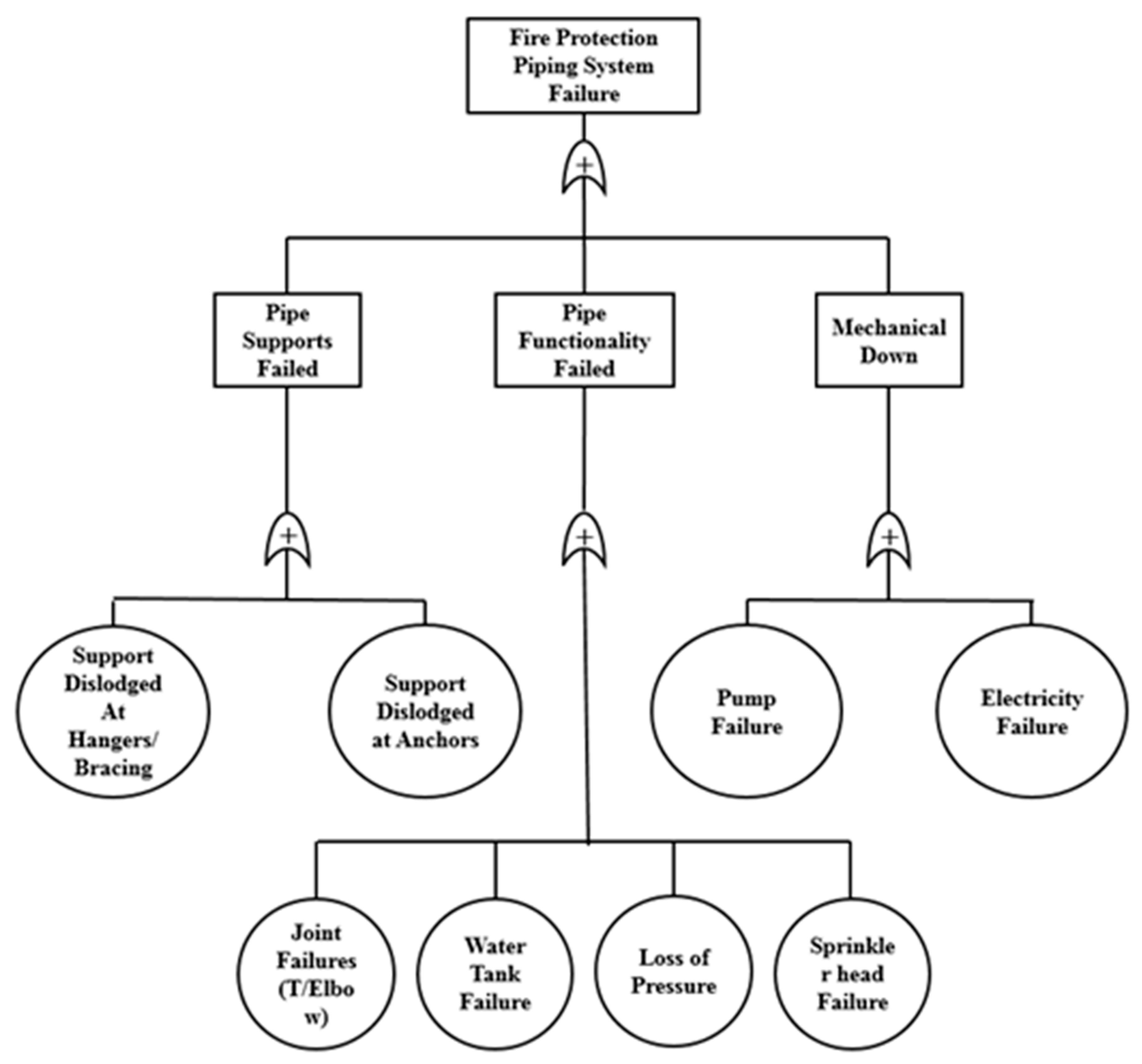
Figure 1 shows a representative fault tree of a fire protection piping system.
Pipe support failures can be defined as supports dislodged at hangers/bracing or at the anchors. Joint failures, water tank failures, loss of pressure, or sprinkler head failures will cause functionality failures in a piping system. Moreover, pump failures or electricity failures can lead to mechanical shutdowns. Ultimately, piping system failures can result in all three major sub-system failures.
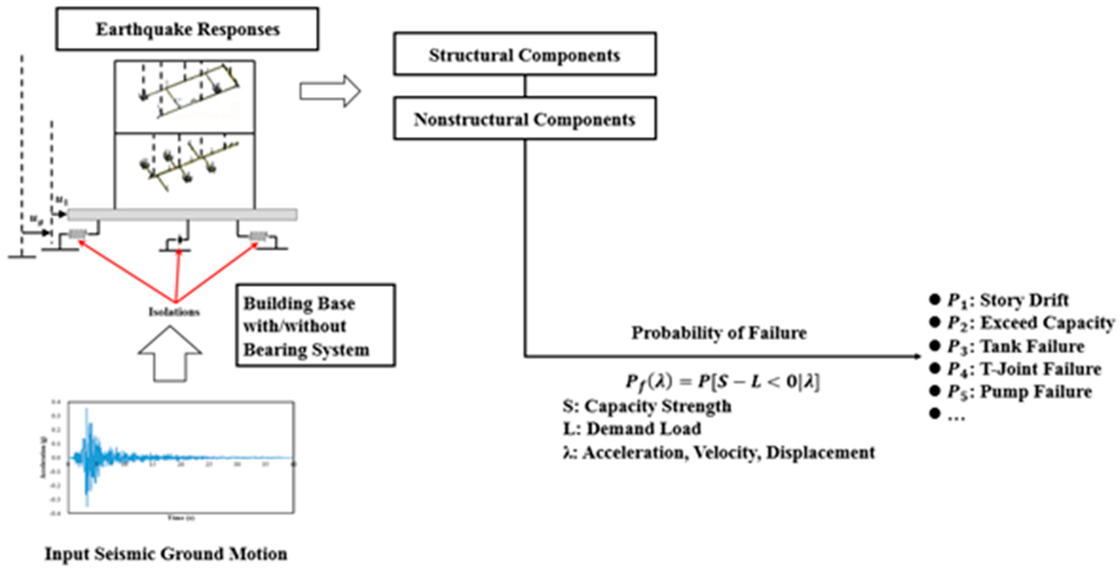
This study focused on the prediction of functional failures corresponding to the leakage of a piping system at a given level of input seismic excitations. The framework of the probability of functional failures in a piping system subjected to strong ground motions is shown in
Figure 2. The probability of failure can be classified as: (1) Occurring in normal daily use, and (2) caused by an earthquake; this study focuses on the latter. The failure probability of a piping system, specifically leakage damage, can be estimated through the displacement response in the piping system subjected to various levels of seismic excitations. We developed a numerical model of a building-piping system with a base-isolated structure, with priority given to estimating the functional probability of piping failure.
2.1. Numerical Modeling
Numerical simulations using a nonlinear building-piping model, with and without a bearing system, are often developed using the Open System for Earthquake Engineering Simulation (OpenSees). A nonlinear finite element model for the T-joint connections and bearings were experimentally validated with the experimental results and were incorporated step-by-step into the building-piping model [
11,
12,
13]. A specified value of 2% damping ratio was used for steel structures, while the damping ratio 5% was used for concrete structures.
2.2. Piping Model
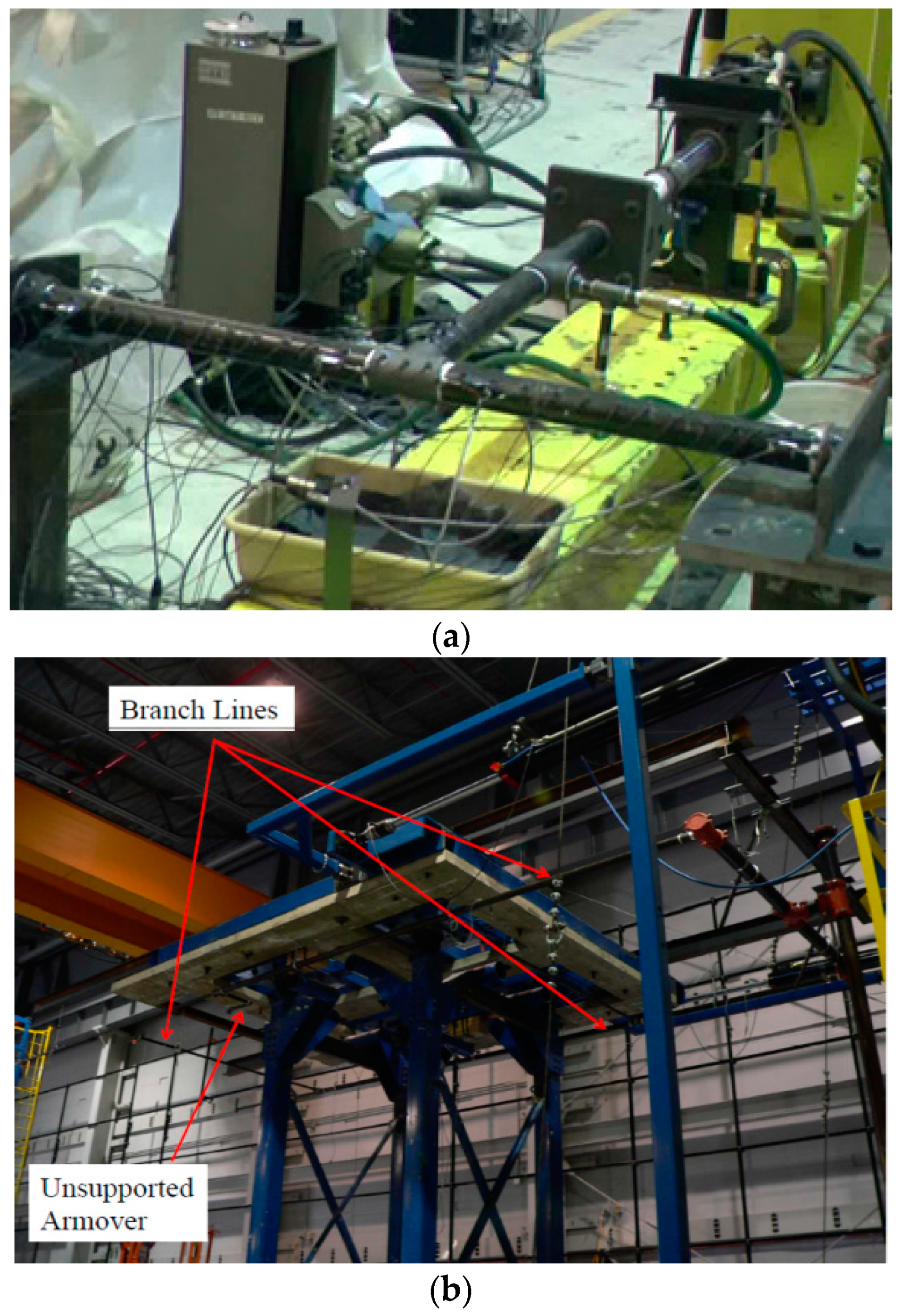
A series of component-level laboratory tests using common black iron piping materials and threaded connections for sprinkler piping systems were conducted by the University at Buffalo, State University of New York [
14,
15], as shown in
Figure 3a. Various sizes of pipes, specifically 100 mm (4 inch), 50 mm (2 inch), and 25 mm (1 inch), were included so that the component-level test data could be used for validation of the system-level experimental study. To detect water leakage, monotonic and cyclic tests were conducted by applying loading at the bottom of the T-shaped component in the in-plane direction while the piping was pressurized at the level of municipal water pressure. During the tests, the leakage was attributed to slippage and rupture at the T-joint connections. The component-level nonlinear moment-rotation models were validated and developed by Ryu et al. [
13] and Ju et al. [
16], and were then applied at each T-joint connection for the system-level model.
System-level laboratory tests were also performed as shown in
Figure 3b, and a finite element piping model with respect to each recognized failure was validated by Ryu et al. [
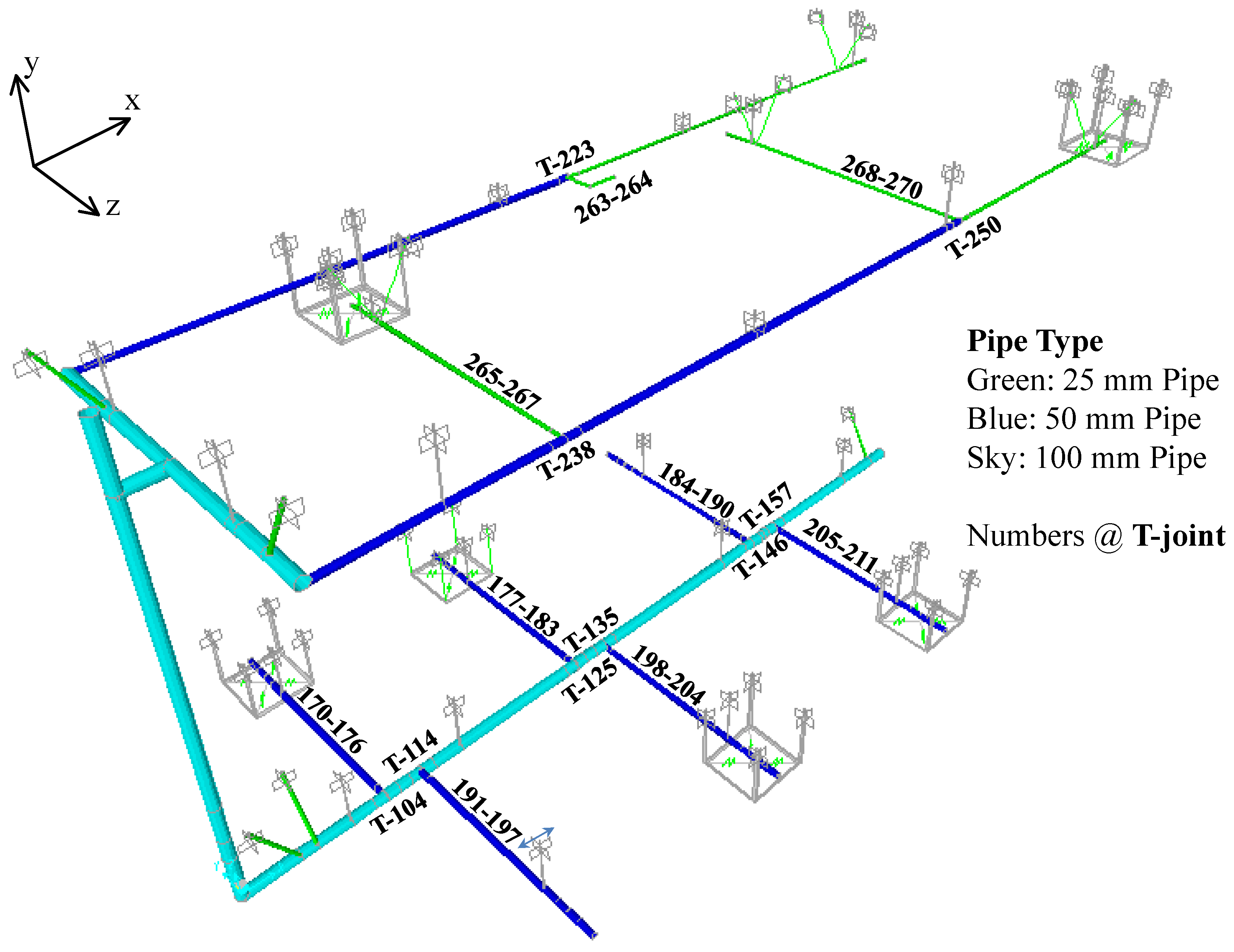
13] using the provided experimental data. The largest pipe diameter 100 mm (4 inch) was selected for the main pipe line and riser, and the branches consisted of 50 mm (2 inch) and 25 mm (1 inch) pipes, as shown in
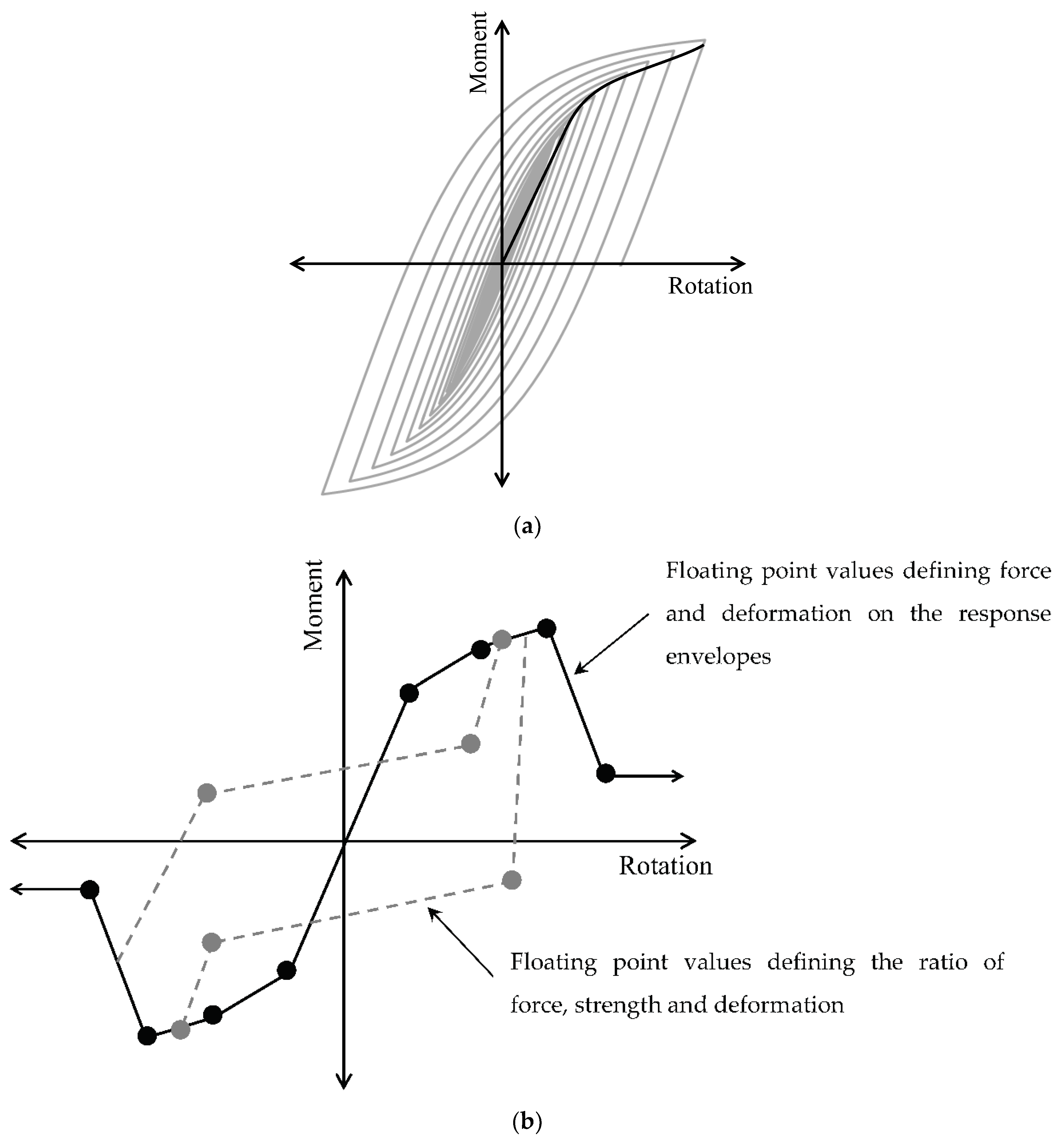
Figure 4. Linear elastic frame elements with gross pipe section properties were used for these piping lines and branches in the numerical modeling (i.e., the failure or leakage was not expected in a frame). Schedule 10 pipes with steel groove fit connections were used for the main line and riser, Schedule 40 pipes with black iron threaded connections were used for the branch lines, and three kinds of nonlinear rotational spring models (25 mm, 1 inch; 50 mm, 2 inch; and 100 mm, 4 inch) were used for the T-joint connections. The hysteretic behavior of the T-joint connections for the 25 mm (1 inch) piping was characterized by yield strength, initial stiffness, and hardening stiffness, as shown in
Figure 5a. The isotropic hardening parameter defines the increase of the compression/tension yield envelope as a proportion of yield strength after a plastic strain.
Figure 5b shows the hysteretic behavior of the T-joint connections in 50 mm (2 inch) and 100 mm (4 inch) piping in which the behavior is characterized by “pinched” moment-rotation responses. Complete details on defining the rotational spring models can be obtained from Ryu et al. [
13]. Various types of supports (transverse sway braces, longitudinal sway braces, wire restraints, and vertical hangers) were used in this system, and it also included sprinkler heads and ceiling boxes. The ceiling tiles were characterized as an elastic material in OpenSees (Mazzoni et al. [
17]) to consider the interaction between the piping branches and the ceiling system. A detailed discussion on the reconciliation and validation of the components as well as the system-level piping models with their experimental results is presented in Ryu et al. [
13] and Ju et al. [
12].
2.3. Building Model
A reinforced concrete special moment-resisting frame (RC-SMRF) building of four stories was used to study the effects of piping interactions with a building, as described in the previous section. This model was originally modeled by Wood et al. [
18], adhering to the governing requirements of the International Building Code (IBC) [
19] and Chapter 21 of ACI 318-14 [
20] and modified as a four-story building, as shown in
Figure 6. In particular, the sum of the moment capacities at the columns was designed to be at least 20% greater than the sum of the moment capacities at the beams based on the strong column-weak beam design methodology. The design model was assumed to have five transverse bays (7.4 m long), longitudinal bays (9.1 m long), and the same story height (3.7 m). For the boundary condition, the building was assumed to be fixed at its base with a solid foundation.
Figure 6 shows the two-dimensional model discretization using a single bay for the reinforced concrete building, and details of the beam and column members are summarized in
Table 1. The complete details and design methodology on developing RC-SMRF building models are given in Wood et al. [
18].
2.4. Bearing Model
Base isolation is an effective system to enable structural or nonstructural components to survive a potentially devastating seismic impact without significant changes to the original design. Recently, the Triple Friction Pendulum (TFP) element was added in OpenSees [
17], wherein TFP bearings were experimentally validated in the NEES/E-Defense research program [
21].
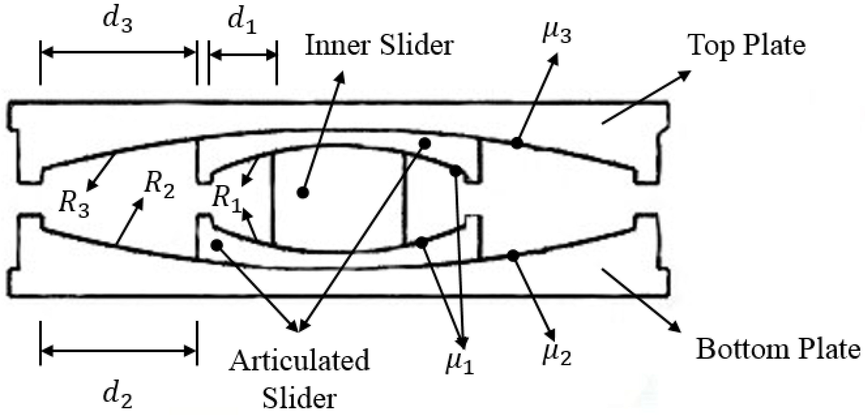
Figure 7 shows the design of the TFP bearings. The behavior of these bearings is characterized by a serial combination of bidirectional elastic-plastic springs and circular gap elements. An inner slider allows the bearing to move between two articulated sliders with two spherical surfaces. The friction coefficient
μ1 is related to sliding of the spherical radius
R1 corresponding to relatively small seismic movements; the friction coefficient
μ2 is related to sliding of the spherical radius
R2, which is designed to engage moderate seismic movements; and the friction coefficient
μ3 is related to sliding of the spherical radius
R3, which is designed to move only for large seismic events. The displacements of the inner slider and the articulated sliders are limited by the size of the bearing, denoted by parameters
d1,
d2, and
d3 in
Figure 7.
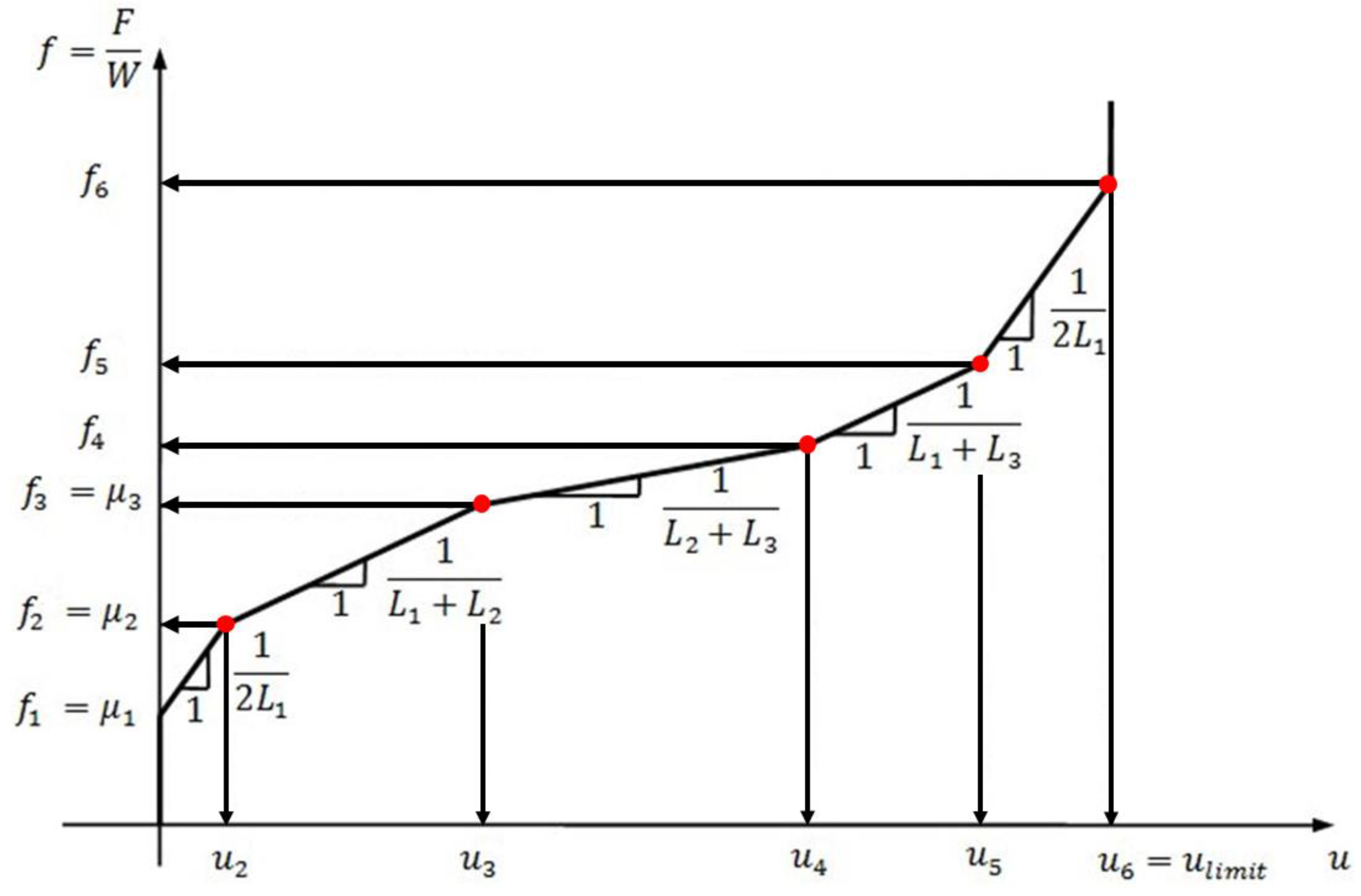
The horizontal movement of the bearing is divided into five stages, as shown in the force-displacement curve in
Figure 8. The curve (movement of the bearing) is defined by the normalized stiffness
k and the maximum displacement and normalized force for each stage. A total of nine independent parameters (three friction coefficients
μ, three pendulum lengths
L, and three displacement limits
d) were selected for the design criteria. The seismic response of the TFP bearings defined by these parameters reduces the spectral demand on the structure due to hysteretic energy dissipation of the isolation system. The target friction coefficients of the TP bearing were
μ1 = 2% and
μ2 =
μ3 = 8%, the radii of curvature were
R1 = 457 and
R2 =
R3 = 3962, and the displacements of the insolation system were
d1 = 51 and
d2 =
d3 = 514. A detailed discussion on the reconciliation and validation of the TFP bearings with the experimental results is presented in Dao et al. [
21].
3. Time History Analysis
We conducted nonlinear time history analyses of multi-story piping systems coupled with seismic-isolated low-rise buildings using a total of 21 ground motions as proposed in the ATC-63 project, published as FEMA P695. A variety of fault mechanisms, such as normal, reverse, and strike slip fault, and local conditions such as site class C or D, were considered to select the earthquake records.
Table 2 shows detailed characteristics of the ground records considered in this study. The data were recorded in various countries, the magnitude of the selected earthquakes was greater than 6.0 Mw in every case, and the range of peak ground accelerations (PGA) was 0.210–0.822 g. We used the building-piping integrated models with and without a bearing system, subject to the normalized 21 different ground motion records, for the nonlinear time history analyses. Such analysis can elucidate the effect of the piping interaction with the building when evaluating the piping seismic fragility.
4. Characterization of Damage State
Ju et al. [
16] and Ju and Gupta [
11] characterized system failure in terms of the first leakage and, if observed, in terms of the pipe fracture. The characterization of the damage state in the structural components or the system of piping systems in terms of a limit state should be convinced to evaluate the system failure. The limit state should be representative of a formal criterion corresponding to the observed failure and damage. Based on our experimental observations, rotations at the T-joint connections are a good engineering demand parameter to characterize the limit state corresponding to the first-leakage instance. Moreover, a probabilistic characterization of the rotation-limit state is suitable if the parameters of the probabilistic distribution are characterized using the deterministically calculated limit-state as per the ASME Boiler and Pressure Vessel Code, Section III [
22]. Since the rotational limit-state specified by any criterion represents a capacity of the component, it is desirable that the limit-state corresponds to a low probability of non-exceedance. For example, Ryu et al. [
23] propose that the rotational limit-state should correspond to a probability of non-exceedance of 1%, based on the alternative form of the ASME [
22] criterion.
A complete definition of the probabilistic distribution for the limit-state also requires a knowledge of the coefficient of variation in addition to the limit-state calculated based on the ASME [
22] criterion. A probabilistic characterization of the limit-state at each of the T-joint locations would enable fragility assessment at each individual joint in the system independently. Then, one can compare the fragility curves for various T-joint locations in the system to determine the particular joint(s) that are most critical/fragile.
5. Seismic Fragility of Piping System
Seismic fragility
Pf(
λ) is defined as the conditional probability of failure when a system attains or exceeds a specified damage criterion,
G(−), at a given intensity of ground motion excitation
λ, e.g., peak ground acceleration (PGA). The damage state
G(−) is defined by the demand
L (load) and the capacity
S (strength) of a system. The fragility
Pf(
λ) can be defined as the probability when
S ≤ L at a given level of
λ. Mathematically, this can be expressed as:
According to Ryu et al. [
23] and Ryu [
24], the capacity
S of a threaded pipe joint can be characterized in terms of a probability of not exceeding a limiting rotation
θLimit of 1%. In this case, the system fragility is defined as:
Fragility can be estimated empirically by conducting multiple nonlinear time history analyses using experimentally validated, nonlinear finite element models for various ground motions.
Here, θi,λ represents the maximum rotation from the ith earthquake time history analysis at a PGA level of λ. 1(–) is the indicator function, and the fragility curve is assumed as an idealized cumulative distribution function.
6. Fragility Evaluation of Base-Isolated Building-Piping Systems
To estimate the sustainability of a multi-story piping system in accordance with the fragility evaluation, we conducted nonlinear time history analyses of the building-piping system model subjected to 21 ground motions. All of the individual ground motions were normalized to the considered PGA level (λ) in Equations (2) and (3), from 0.2 g to 2.2 g at an interval 0.2 g. Moreover, to elucidate the performance of the TFP bearing system in the building, piping systems installed in both the isolated building and the fixed-base RC-SMRF building models were used.
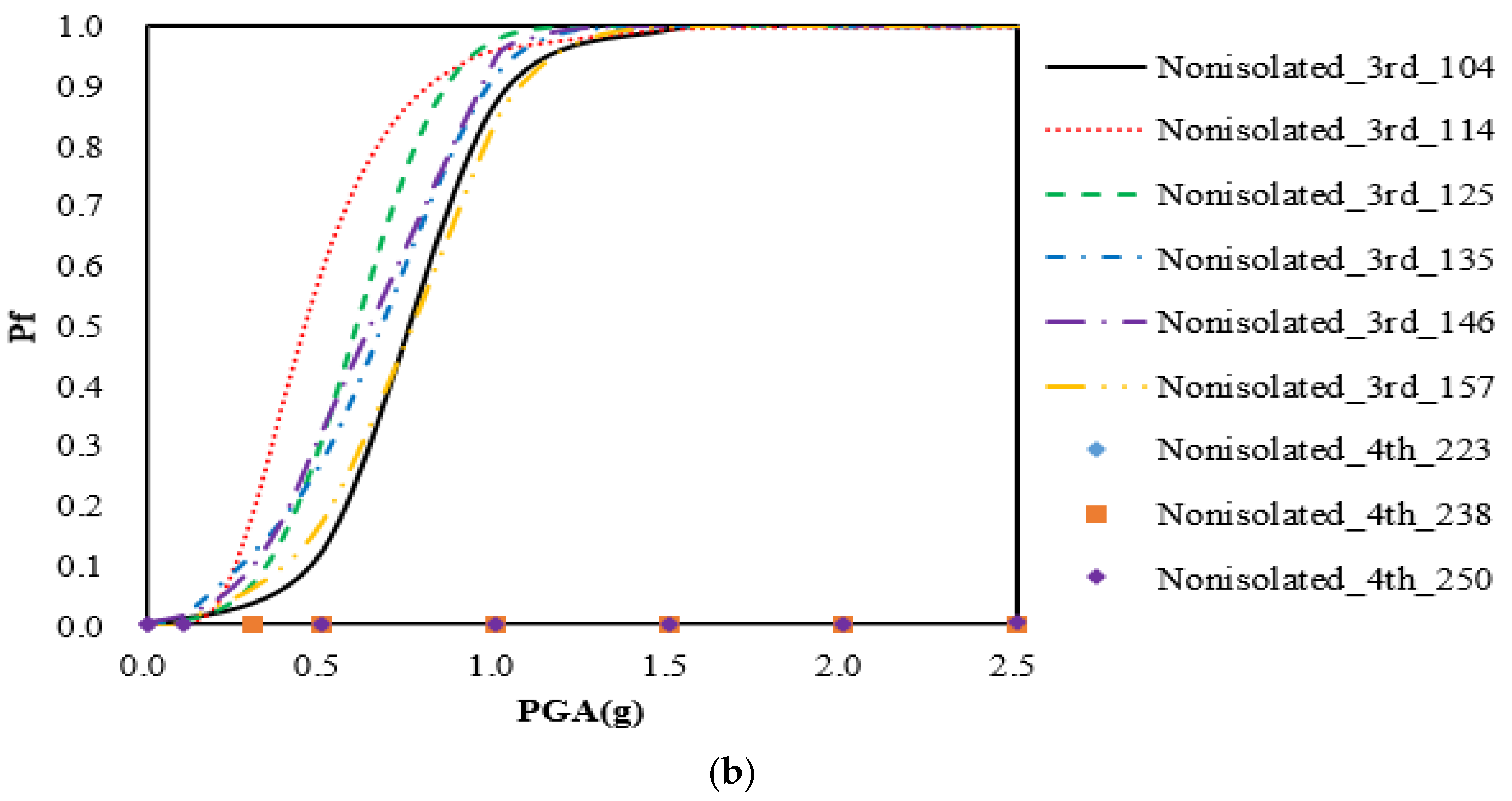
The seismic fragility of the multi-story piping system at each threaded T-joint is shown in
Figure 9. The seismic fragilities are illustrated at different levels, from the first floor to the fourth floor in the building. The fragility comparisons showed that the fragility of the third and fourth floors was more severe than that of the first and second floors, because the upper-floor acceleration is greater than the lower-floor acceleration in a linear building. In addition, there was no piping failure up to 2.5 g on the second and fourth floors because the piping frequency at those levels was far from the building frequency. Of interest was the observation that the 20 mm (1 inch) black iron pipe was more ductile than the 50 mm (2 inch) pipe, based on the displacement performance of the piping T-joint system.
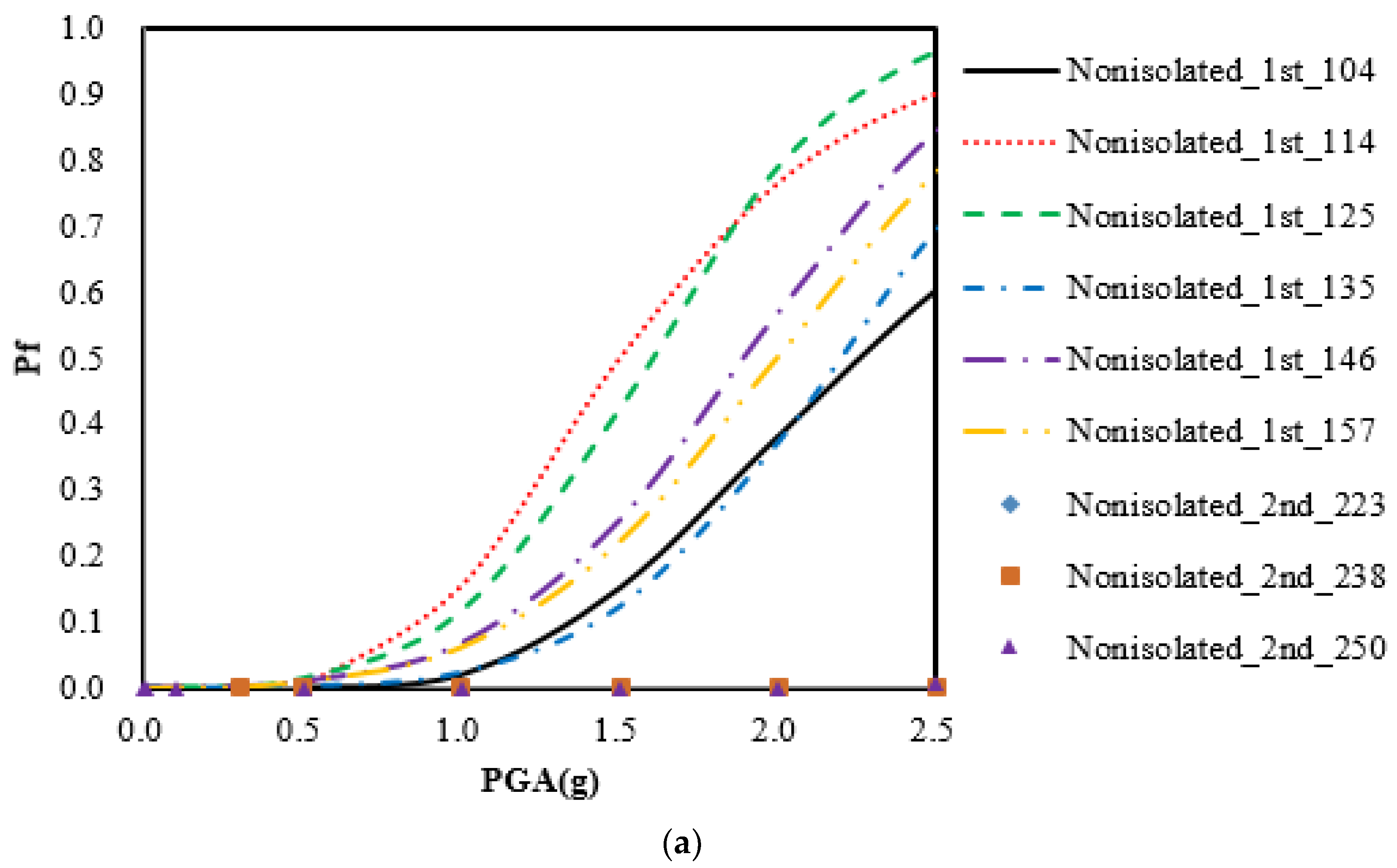
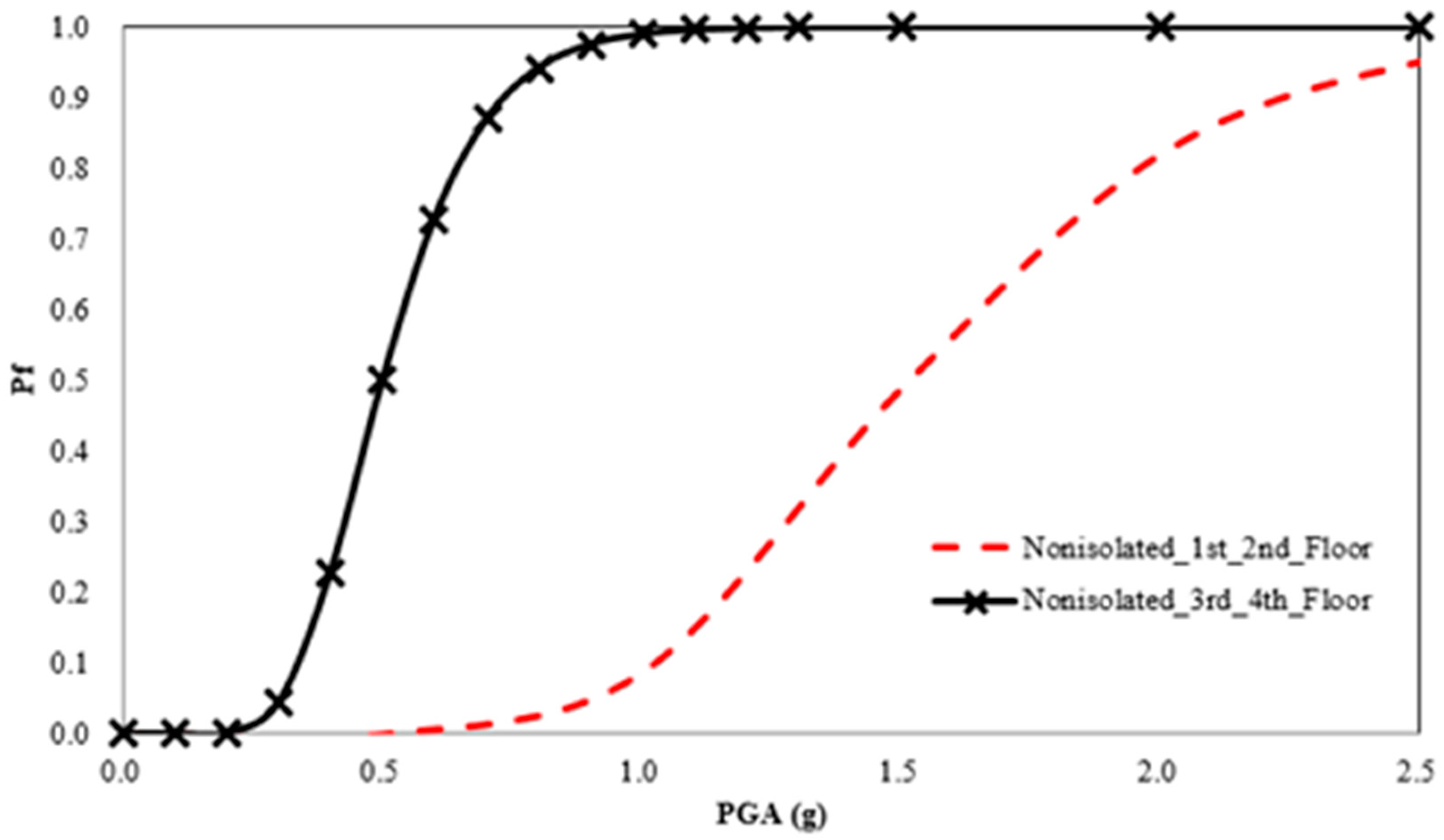
Figure 10 shows the system-level multi-story piping fragility for the fixed-base building structure. The system-level failure was defined as wherever a component failure was detected. The figure clearly shows that the upper level of the piping system was more fragile than lower level in the linear building.
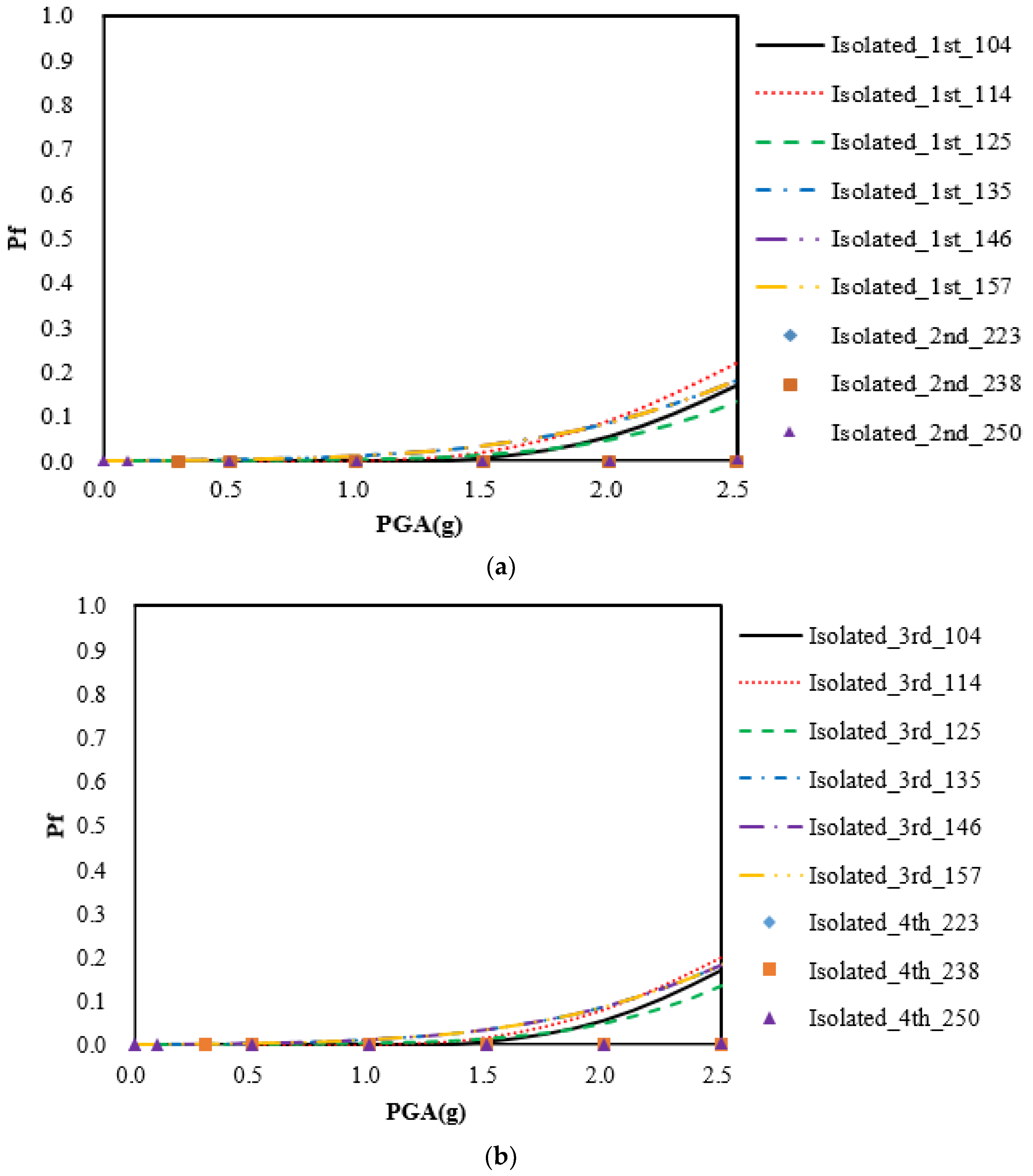
Figure 11 gives the multi-story piping fragility curves on different floors in the seismically base-isolated building system. Of note is that the probability of failure at the piping T-joints was lower than 20% at PGA 2.0g, and the fragilities of the piping system in the base-isolated building system had similar trends in the probability of failure from PGA 0.2 g to 2.5 g.
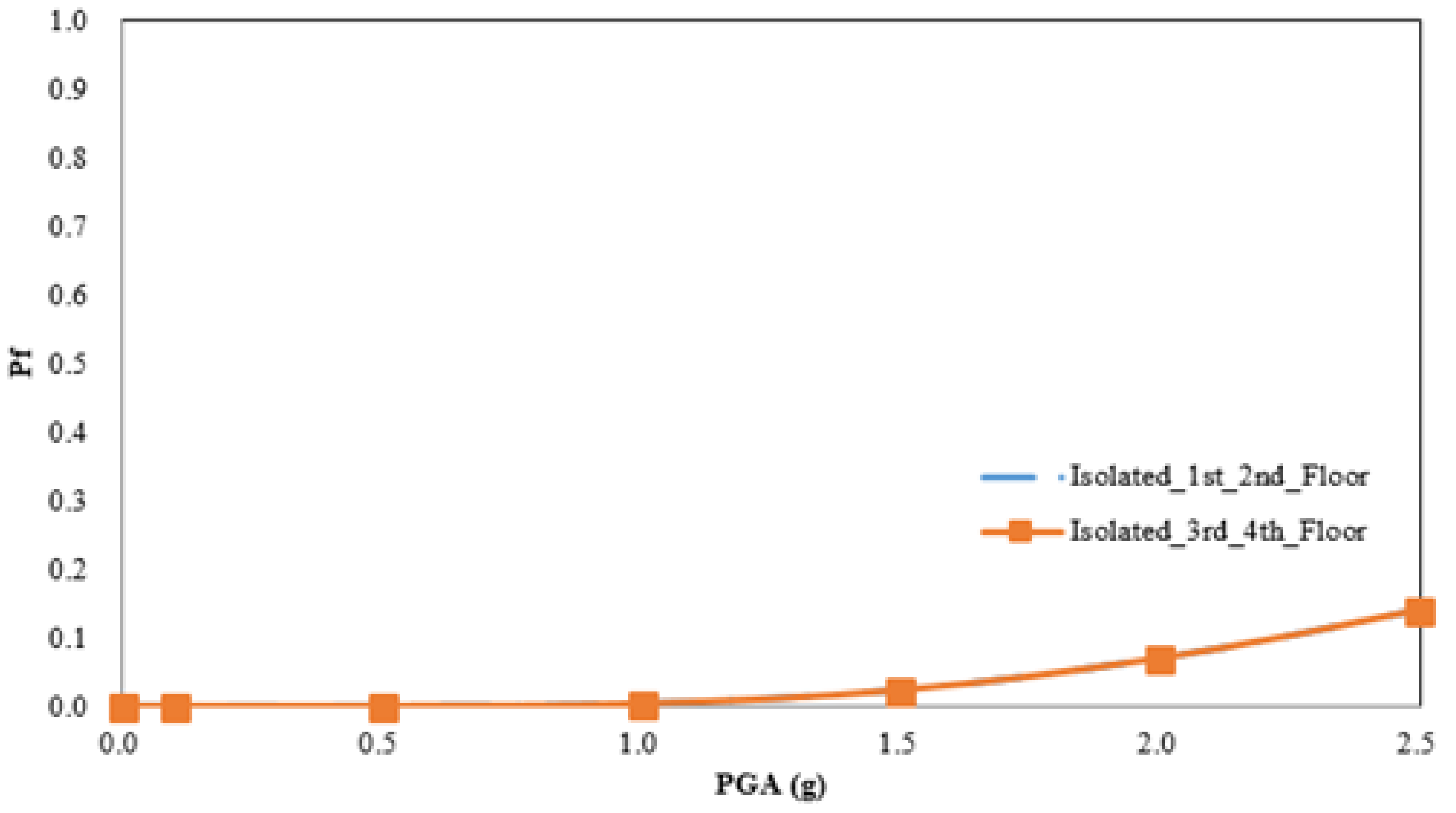
Figure 12 shows that the system-level fragilities of the seismically base-isolated piping system were very close to the probability of failure on floors 1 and 2, and 3 and 4. The reason is the performance of the TFP bearing system. Due to the TFP system, the building was isolated from ground motions, and the acceleration of each floor was similar. Thus, the probability of failure was almost identical in both the component- and system-level fragilities. This clearly demonstrates that the influence of the seismic isolation system was significant.
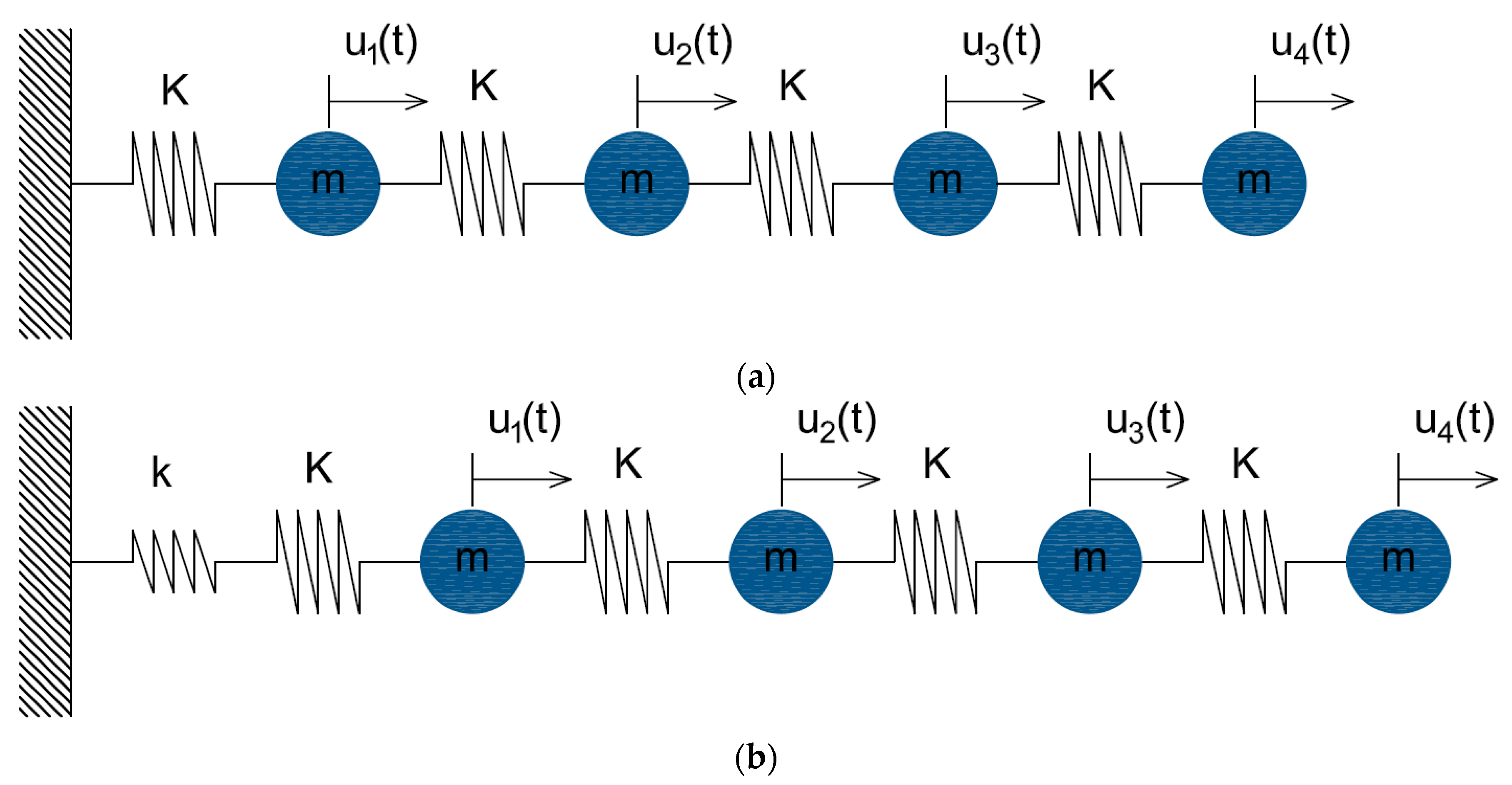
Figure 13 shows the schematic design of a low-rise, base-isolated building model. The flexible spring representing the seismic base isolation system was connected with the building system, and the two-spring system coupling with the first-floor mass was combined as a single-spring model. Due to the flexible spring system, the fundamental frequency of the integrated structural system with a bearing was shifted from a relatively large value to a small value compared to the non-isolated building structure without a bearing. In other words, such a flexible spring brought large displacement in the spring itself and, accordingly, protracted the structural period of the integrated system, causing quasi-rigid body motions in the building structure.
In addition, the mass participation and the effective mass for the second mode associated with the building structural deformation was nearly negligible. This is attributed to the fact that the second mode was related to the orthogonality to the seismic ground motions; thus, the difference between the seismically isolated building-piping system and non-isolated building-piping system was increased. In a nutshell, by decreasing the original structure frequency of the building through utilizing a seismic isolator, the seismic acceleration of the floors of the building structure was significantly decreased during strong seismic ground motions. Accordingly, the seismic performance of the piping system was greatly increased. Due to these effects, the probability of failure of the multi-story piping system within the seismically isolated building structure was drastically decreased compared to that of the piping system in the non-isolated structure.
7. Conclusions
This paper presents the effects of a seismically isolated bearing system on a building-piping model for probabilistic seismic risk assessment, in consideration of the sustainability and functionality of the multi-story piping system being subjected to strong ground motions. Building models with and without TFP elements were produced, and the particular focus was on the estimations of seismic fragility of the multi-story piping system within the base-isolated building structure. Multi-story piping systems were installed in four-story RC-SMRF buildings, and were then coupled with the building isolation system for nonlinear time history analyses, followed by evaluation of the seismic fragility of the piping systems. The key conclusions of this study are:
- (1)
From sophisticated analytical models of nonlinear building-piping structures subjected to strong ground motions, qualitative observations illustrated the seismic fragilities at the T-joint levels of each floor, and then the system-level fragilities in the multi-story piping systems were estimated.
- (2)
The system-level fragility of the piping systems on the third and fourth floors in the non-isolated building-piping structure was greater than on the first and second floors because the upper-floor acceleration is larger than the lower-floor acceleration in a linear building.
- (3)
The fragilities of the seismically isolated piping system tended to show a drastically lower probability of failure than those of the non-isolated piping system, and the system-level fragilities on floors one and two, and three and four were very similar since the building structure led to the behavior of quasi-rigid motion on the isolated system.
- (4)
A seismic-isolation building design improved the sustainability and functionality of the piping system during a simulated earthquake. In particular, coupling the building-piping system with the isolation system could improve sustainability during beyond-design-basis events because the coupled multi-story piping system in the seismic-isolated building could experience significantly lower accelerations over all the floors of the building.


