1. Introduction
Traditional cloud application providers (CAPs) deploy network function via dedicated hardware [
1], meaning network function is, consequently, closely linked to a device. When a user’s demands change, the CAP must adjust and upgrade the hardware network to adapt to this change. Even with small changes at the functional level, the underlying equipment may require adjustment for a long time, and the flexibility and scalability of the network are limited.
With the rapidly increasing popularity of cloud computing, the number of cloud application requests has dramatically increased, and traditional operating models have been unable to handle high-frequency device updates and upgrades in cloud computing. However, network function virtualization (NFV) [
2] implements the separation of software and hardware; it overcomes the drawbacks that specific functions cannot be quickly upgraded, due to the attachment of the dedicated hardware in the traditional mode and substantially improves the flexibility and scalability of a network. Therefore, NFV is favored by cloud application providers.
A service function chain (SFC) is the main form of NFV to implement cloud applications. Each SFC is composed of a sources node, destination node and multiple virtual network function (VNF) modules, which are connected in order by virtual links. Thus, an arrived cloud application request is abstracted to the corresponding SFCl and deployed to the underlying network of cloud computing.
Previous studies of SFC deployment primarily focused on network delay, network reliability, and network service quality and rarely considered power consumption while provisioning a cloud application. Statistics show that the power consumption of a cloud data center is equivalent to the power consumption of 25,000 homes [
3]. Amazon’s evaluation of its data center shows that the cost of operation and maintenance accounts for 53% of the total budget of the data center, whereas 42% of the operation and maintenance cost stem from power consumption [
4]. The annual electricity cost of the Akamai Company in the United States is approximately 10 million US dollars [
5]. China Mobile consumed 13 TWh of energy in 2011 [
6]. Telecom Italia consumes 2 TWh of energy each year [
7].
High power consumption will shorten device life, create energy waste and carbon emissions, and aggravate the greenhouse effect. However, reducing the power consumption that is used to map the virtual network function can generate lower costs, increase revenue for cloud application providers, and improve commercial competitiveness in industry. Therefore, implementation of an energy-aware management strategy for infrastructure resources is necessary, and the need to perform energy-aware virtual network function deployment research for cloud application provision is urgent. The main contributions of our work are detailed as follows:
We implement energy-saving SFC deployment in a wavelength division multiplexing (WDM)-based optical cloud network. We briefly describe the energy-efficient next-hop selection (ENSF) algorithm, proposed in Reference [
8], and analyze its advantages and disadvantages.
We propose the new algorithm direction-guided FirstFit (DGFF), which introduces “direction guidance”. This algorithm employs efficient and accurate path-finding strategies that significantly improve its performance in cloud application provisioning.
We introduce the concept of “load balancing” and propose the direction-guided greedy (DGG) algorithm, which is based on the DGFF algorithm. DGG can reduce network bottleneck nodes and links and improve network stability.
We simulate the proposed algorithm in terms of the SFC total acceptance ratio, SFC average power consumption, average mapped cost, the average running time of the algorithm, average node load ratio and average link load ratio of the network. We make an objective comparison to analyze their performance. A large number of simulation results show that the DGFF algorithm and the DGG algorithm are superior to the ENSF algorithm [
8] in cloud application provisioning.
The remainder of this paper is structured as follows:
Section 2 introduces related studies;
Section 3 introduces and describes the SFC deployment model;
Section 4 proposes a heuristic algorithm to implement energy-saving SFC deployment;
Section 5 presents and analyzes the simulation results; and
Section 6 concludes the paper.
2. Related Work
Numerous studies have focused on the problem of VNF deployment for cloud applications. The authors in References [
9,
10,
11,
12,
13,
14,
15,
16,
17,
18,
19,
20] provide the method and purpose of early virtual network deployment: Improve Internet service provider (ISP) revenue by mapping more virtual requests to the same underlying network. We compare the performance of the proposed algorithm with existing algorithms, which as shown in
Table 1.
In Reference [
21], the authors abstract the cloud application-based SFC deployment as an optimization model and propose the heuristic algorithm. By introducing Markov approximation to calculate the priority deployment node of the SFC, then calculating the node that preferentially accepted the SFC and reducing the solution space of the model, algorithm convergence was accelerated. The algorithm attempts to integrate each SFC into a single or similar physical node and reduce overhead by sharing physical resources.
Yang et al., in Reference [
22], proposed an algorithm called merge-RD. They defined a physical quantity, “relational depth” (RD), between VNF modules. They tried to integrate the deep relational modules into the same or similar physical nodes by calculating RD. In this manner, the interaction traffic of the network can be reduced to decrease the power consumption.
W. Racheg et al., in Reference [
23], abstracted the SFC deployment problem into an integer linear programming (ILP) model and proposed the extensive search algorithm (ESA). They used the brute force method for each SFC to search for all possible paths between its source and destination, calculated the total revenue for each, and chose the path with the highest income. However, in a large and complex network, algorithm convergence will be very slow, because the possible solution space of an actual operation is too large. Therefore, ESA is not suitable as an online SFC mapping algorithm for cloud applications.
In the studies reported in References [
24,
25], on virtual network deployment, the authors divided the whole process into two parts: Node mapping and link mapping. In the node mapping process, the authors considered whether the available physical nodes are matched with the requirements of virtual nodes, and whether the selection of the current physical nodes is beneficial to subsequent link mapping. Then, they chose the optimal node as the target. The link mapping process is based on node mapping, where the authors adopted the shortest path strategy to find the optimal path between the mapped nodes to complete the mapping process. The authors in References [
26,
27,
28] believed that an ordered VNF map (i.e., SFC map) is essentially a special virtual network embedding (VNE) map or an extension of the VNE; however, they have different goals and constraints.
M. Tajiki et al., in Reference [
8], proposed a novel resource allocation architecture that enables cloud application-based SFCs to be deployed to SDN-based networks with minimal power consumption. For this reason, they considered the VNF layout, VNF allocation to flows and flow routing for optimization, and modeled the problem. In addition, they modeled traffic rerouting to reduce the impact of resource fragmentation on network utilization. Since then, the authors proposed a heuristic algorithm for various optimization problems and evaluated the performance of the proposed algorithm in the actual topology under various network traffic patterns. The results confirm that the proposed heuristic algorithm provides a near-optimal solution in an execution time that is applicable to the actual network.
In Reference [
29], the authors used the GWATT tool from Bell Labs to estimate the possible energy-saving effects of three major NFV use cases: (1) Virtualized evolved packet core (VEPC); (2) virtualized customer premises equipment (VCPE); and (3) virtualized radio access network (VRAN). They determined that the mobile network with the highest energy utilization prospect is the evolved packet core (EPC); the virtualization produced a 22% reduction in power consumption and a 32% increase in energy efficiency. The authors also showed that power consumption savings will be even higher if traffic on the network is increased.
3. Preliminaries and Modeling
3.1. SFC Mapping
We use an undirected weight graph to describe the cloud application-based SFC model:
Gv = (
V,
E,
Rv,
RE), where
V and
E denote the VNF module set and the virtual link set, respectively. The resource requirements of the VNF modules and links are denoted as
Rv and
RE, respectively. As shown in
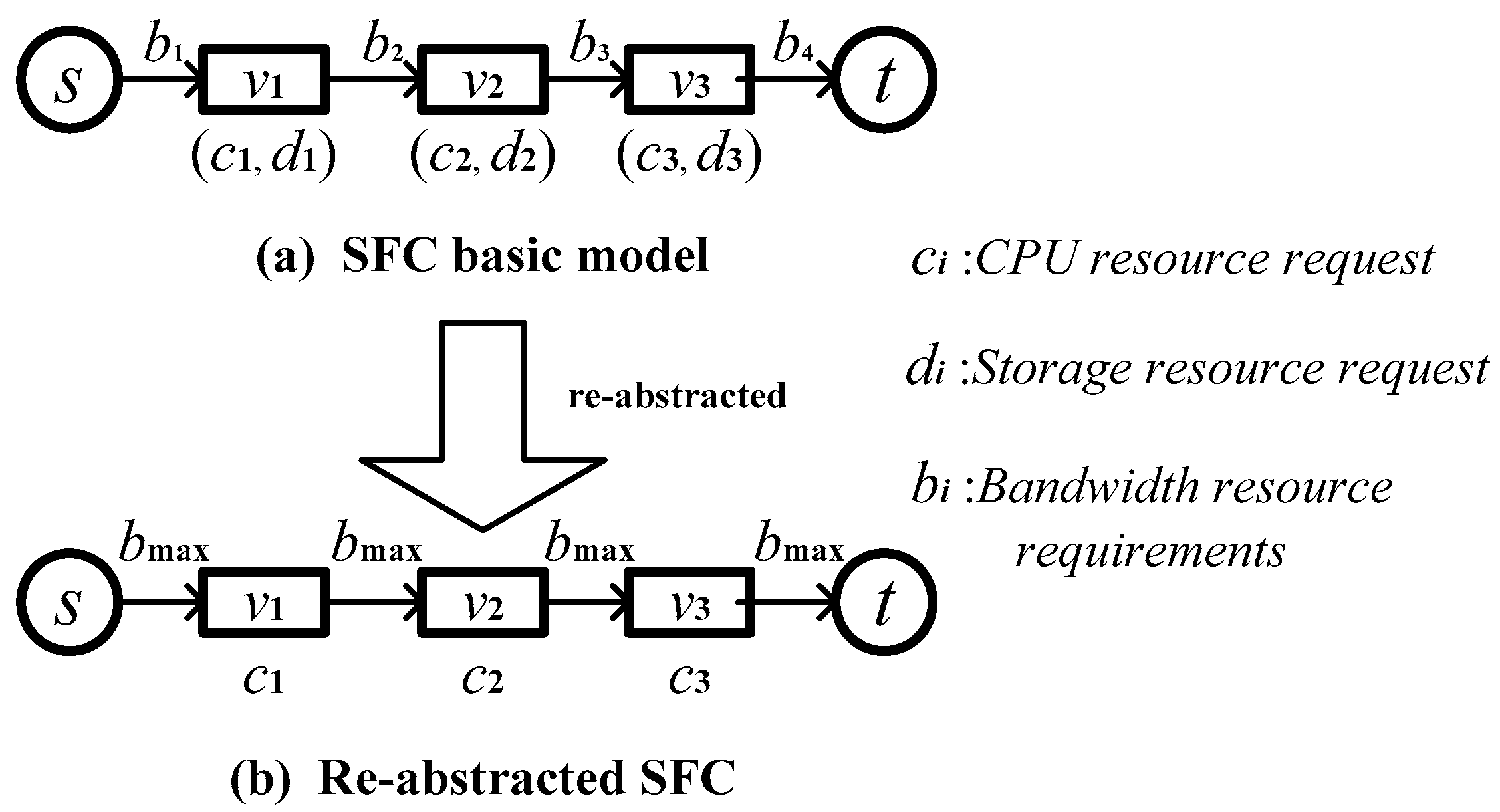
Figure 1a,
s indicates the SFC source physical node,
t indicates the destination physical node,
vi indicates the VNF module,
ci is the corresponding central processing unit (CPU) resources requirement,
di indicates the storage resource requirement, and
bi indicates the virtual link bandwidth requirement for a cloud application. We know the resource requirements of the VNF module are mainly CPU resources (computing resources) and storage resource requirements. The virtual link resource requirements are mainly link bandwidth requirements.
There are fewer CPU computing resources in the physical node resources, and the hardware storage space is usually large enough [
30]. To increase the convenience of the subsequent simulation, we re-abstract the cloud application-based SFC model. As shown in
Figure 1b, we only consider the CPU resource requirements of the VNF module, and the bandwidth requirement of the virtual link is set to the maximum of all the bandwidth requirements.
The main problem of cloud application-based SFC deployment is identifying a physical path between a source node and destination node on the underlying network that can carry all VNF modules of the SFC. This deployment process needs to satisfy certain constraints.
Figure 2 shows the deployment process of a cloud application-based SFC: The source and destination nodes of the SFC are mapped onto the physical nodes A and D, and the VNFs are mapped in sequence. The green nodes represent the physical nodes that carry the VNF modules. The mapping pairs are as follows: (
v1, A), (
v2, B), and (
v3, E); this follows the one-to-one mapping principle (a physical node can only carry one VNF of the SFC). The hollow nodes represent the forwarding nodes that do not carry the VNF module, the virtual link is mapped to the physical link, as shown in the green link in
Figure 2, and the mapping pairs are as follows: {(
v1,
v2), (A, B)}, {(
v2,
v3), (B, E)}, and {(
v3, D), (E, D)}. The traffic passes through all VNF modules of the SFC in the direction of the green arrow in
Figure 2.
After a cloud application-based SFC is expired, all server resources and communication resources allocated to the SFC are recovered and managed by the underlying network.
3.2. Underlying Network
The underlying physical network topology used in this paper is a WDM-based optical network [
31,
32,
33,
34,
35]; its communication link medium is optical fiber. There are optical transmitters and optical receivers at the end of the fiber link, and there are optical amplifiers on the link. Thus, the fiber links will introduce more link power consumption than the traditional physical link.
Figure 3a shows a more realistic WDM network model.
In this model, the underlying sites consist of two parts: (1) Server nodes, which provide server resources, such as CPU resources and storage resources; and (2) WDM nodes, which provide communication resources, such as optical signal receiving and sending, data flow forwarding, and optical wavelength conversion. The main resource of the underlying link is wavelength capacity, which can also be understood as bandwidth capacity.
To facilitate the subsequent simulation, we abstract the original WDM network model in this paper, as shown in
Figure 3b. Additionally, we abstract the sites consisting of the WDM node and the server node into the integrated nodes, which include all functions and attributes of the sites under the original model; the link model is almost unchanged. We use an undirected weight graph to represent the abstract model, which is denoted by:
Gs = (
N,
L,
AN,
AL), where
N and
L represent the physical node set and the fiber link set, respectively, and each node
n,
has certain server resources (CPU resources and storage resources) and communication resources (wavelength resources and switching capabilities). Each link
l,
has a certain wavelength resource (bandwidth resource).
AN and
AL represent the attributes of the node and the fiber link, respectively; the typical node attributes are the server resource capacity and the communication resource capacity, and the link attribute is the wavelength capacity.
3.3. Power Consumption Model
The power consumption of the cloud application SFC deployment considered in this paper includes two parts: Node power consumption and link power consumption.
(a) Node Power Consumption Model
When physical node n, is in the standby state, it generates a certain load-independent power consumption, called idle power consumption, which we use to denote. In this paper, it is assumed that the node idle power consumption has a linear relationship with the total CPU resources provided by the physical node. When the node carries a certain load, the computational overhead of the VNF module on the node will generate the additional load-related power consumption, which is denoted by in this paper.
In [
36], the authors studied the relationship between the load-related node power consumption and the node load ratio; they found that load-dependent power consumption increases linearly with node load ratio, as shown in Equation (1):
where
represents the power consumption when the node computing resources are fully loaded, and
u represents the node computing resource utilization.
In addition, the underlying network of this paper is based on the WDM network. However, it is usually only in a large-scale network that a few physical nodes with the wavelength conversion function are introduced. Because the underlying network is set to be free from the wavelength conversion, our power model of the underlying network node does not include the conversion power consumption .
Finally, when node n forwards user data, it will generate forwarding power consumption . Compared to idle power consumption and load-related power consumption, forwarding power consumption is lower. For the implementation in this paper, a small random number is generated for each node as the forwarding power consumption; each SFC will generate the forwarding power through the physical node.
In summary, the power consumption model of the underlying node used in this paper is shown in Equation (2).
where
PassedSFC represents the number of SFCs currently passing on node
n.(b) Link Power Consumption Model
There are three main sources of link power consumption in WDM networks: Optical transmitter power consumption, optical receiver power consumption, and optical amplifier power consumption.
User data is processed at the physical node and then sent to the fiber link; it must go through the optical transmitter at the fiber transmitter to achieve electro-optical conversion. Correspondingly, the optical signal received by the physical node at the opposite end of the link must go through the optical receiver to achieve optical-electro conversion. In addition, to compensate for the loss of long-distance transmission and continuous reflection of optical signals, we must introduce the optical amplifier on the fiber link to increase the signal strength to prevent the signal from being incorrectly recognized and processed when it is transmitted to the peer end. Therefore, optical transmitter power consumption, optical receiver power consumption and optical amplifier power consumption will be generated on the link.
The optical transmitter and receiver power consumptions of link
l are denoted as
and
, respectively, and the optical amplifier power consumption is denoted as
. For
and
, the implementation in this paper generates a relatively small random number, and
is related to the length of link
l. In [
37], the authors provide the relationship between them, as shown in Equation (3):
where
dl is the length of fiber link
l in kilometers (km).
Currently, each SFC passing through link
l will generate three corresponding power consumptions:
,
and
. Therefore, total power consumption
of link
l can be calculated according to Equation (4):
where
PassedSFC represents the number of SFCs currently passing on link
l.
3.4. Performance Index
We use the following performance indices to compare the performance of the proposed algorithm to that of the comparison algorithm [
8]:
(a) SFC acceptance ratio:
The SFC acceptance ratio
Ra is the ratio of the number of accepted SFCs to the total number of SFCs that arrived. The definition is as shown in Equation (5):
(b) Average SFC power consumption:
Average SFC power consumption
Paverage is the ratio of the current total power consumption of the network to the number of SFCs that are currently carried. The definition is as shown in Equation (6).
The denominator represents the number of SFCs running on the current network, and the numerator represents the current total power consumption of the entire network.
Ptotal can be calculated according to Equation (7).
The first part of Equation (7) represents the power consumption of all nodes of the underlying physical network, and the second part represents the power consumption of all links of the underlying physical network.
(c) Average node load ratio:
Average node load ratio
UAN indicates the load ratio that each SFC in the bearer state imposes on the underlying physical network node. The definition is shown in Equation (8).
The numerator represents the sum of the load ratios of the underlying physical nodes, and the denominator represents the number of SFCs in the receiving and running states on the current underlying network.
(d) Average link load ratio:
Average link load ratio
UAL indicates the load ratio that each SFC in the bearer state imposes on the underlying physical network link. The definition is shown in Equation (9). The numerator represents the sum of the load ratios of the underlying physical links, and the denominator represents the number of SFCs that are running on the current underlying network.
3.5. Optimization Objective and Constraint Condition
(a) Optimization Objective
In this paper, we study the power consumption overhead reduction of the SFC mapping in the underlying network under the guarantee of a certain SFC request acceptance ratio. The problem is abstracted as an optimization mathematical model, and the optimization objective function definition is as shown in Equation (10):
Objective Equation (10) attempts to reduce the total power consumption of the underlying network, where the first part represents the power consumption of all nodes of the underlying network and the second part represents the power consumption of all links of the underlying network.
(b) Node Constraints
The node constraints that must be met to complete the mapping of service function chains are as follows:
where
hvn indicates whether VNF module
is deployed onto underlying physical node
(if
v is deployed onto
n,
hvn is 1; otherwise,
hvn is 0).
t(
n) represents the number of times the SFC passes through node
n. st(
n) represents whether physical node
n is in the running state (if
n is in the running state,
b is 1; otherwise,
b is 0).
rC(
n) and
avaC(
n) represent the number of computing resources provided by node
n for the SFC and the number of computing resources available at present, respectively.
req(
v) represents the computing resource requirement of VNF module
v.
Equation (11) indicates that each VNF module of the SFC can only be deployed to one node on the underlying network. Equation (12) indicates that each node of the underlay network supports at most one VNF module of the SFC. These two conditions ensure that each VNF module requested by the SFC is mapped into the underlying physical network in a one-to-one mode. Equation (13) indicates that the SFC data flows at most once through each physical node, which ensures that the mapping of SFCs on the underlying network does not create loops. Equation (14) ensures that underlying physical node n will be powered on only if there is an SFC passing through, which avoids introducing unnecessary idle power. Equation (15) is the resource constraint of physical node n, which ensures that the computing resources provided by node n to the SFC must not exceed its own currently available computing resources. Equation (16) indicates that the computing resource provided by physical node n to the SFC is equal to the computing resource requirement of the VNF module deployed onto the node.
(c) Link Constraints
The link constraints that must be met to complete the mapping of service function chains are as follows:
where
hel indicates whether virtual link
is mapped into physical link
l (if
e is mapped into
l,
hel is 1; otherwise,
hel is 0).
rB(
l) indicates the bandwidth resource provided by link
l to the SFC, and
avaB(
l) indicates the available bandwidth resource of link
l at present.
req(
e) indicates the bandwidth requirement of virtual link
e.
bi, j denotes the directed SFC traffic on physical link
<i,
j>,
represents the set of the adjacency nodes of physical node
i,
represents the set of the adjacency nodes of physical node
i, and
B denotes the bandwidth requirement of the SFC.
Equation (17) indicates that virtual link e is mapped into at least one physical link or a physical path that is formed by multiple physical links. Equation (18) indicates that physical link l supports at most one virtual link. Equation (19) is the physical link resource constraint, which indicates that the bandwidth resources provided by physical link l to the SFC do not exceed the available bandwidth resources at present. Equation (20) indicates that the bandwidth resource provided by underlying link l to the SFC is equal to the virtual link bandwidth resource required by the SFC mapped into physical link l. Equation (21) indicates that the inflow at source node s and the outflow at destination node t are 0. Equation (22) indicates that the outflow of source node s and the inflow of destination node t are equal to the bandwidth requirements of the SFC. Equation (23) indicates that the intermediate physical node carrying the VNF module (excluding the source and destination nodes) meets the traffic conservation constraint.
4. Algorithm Design
Because of the disadvantages of the greedy algorithm, if we want to use the local-to-global algorithm to achieve efficient and accurate path-finding, we must introduce auxiliary measures to change the essential characteristics of blind path-finding. In this way, the acceptance bottleneck of SFC can be broken and the path-finding success ratio can be improved. Therefore, in this section, we propose the direction-guided FirstFit (DGFF) algorithm based on “direction guidance.”
As shown in
Figure 4, when an SFC reaches the underlying network, the algorithm first extracts its destination node and then uses the Bellman-Ford algorithm or Dijkstra algorithm to update the minimum hops from other nodes to the destination node in the underlying network. Using this auxiliary parameter, the program can roughly determine the relationship between the number of nodes in the current remaining path and the number of VNFs to be mapped.
For example, if the hop count of the current node is 4 (i.e., there are at least 4 nodes to the destination point without the current node), the number of VNFs to be mapped in the SFC is 3. The algorithm first searches for nodes less than 4 hops from adjacent nodes to see whether they can carry the next VNF module that can quickly approach the destination point. If no node is found that meets the requirements, the algorithm will look for nodes that have the same number hops and can carry the next VNF module in adjacent nodes. If a suitable node still cannot be found, then it will find nodes with hops more than 4 to see whether they meet the requirements. If the number of VNFs to be mapped is 6, then the algorithm first searches for nodes more than 4 hops from the adjacent nodes. The program temporarily seeks the direction away from the destination point in case the number of subsequent nodes is insufficient to accommodate the VNF modules.
The advantage of the DGFF algorithm is that, no matter which node the program is currently on, and which node it is going to next, the program can know whether this step is approaching or moving away from the destination node. In addition, the algorithm also provides a basis for guiding the direction of its own path, which is the relationship between the length of the remaining path and the number of VNFs to be mapped. When the remaining path is short, the path goes away from the destination node; when the remaining path is long, it goes to the destination node. The program achieves efficient path-finding by repeating dynamic adjustments.
The main body of the algorithm is divided into two processes: The downlink process (process = 1), which refers to finding a path to lower nodes (nodes with smaller hops), and the uplink process (process = 2), which refers to finding a path to higher nodes (nodes with larger hops). The algorithm pseudocode is given in Algorithm 1.
| Algorithm 1. DGFF Algorithm |
Input: Underlying network Gs = (N, L, AN, AL);
Service function requests Gv = (V, E, Rv, RE)
Output: node, link mapping pair of SFC on the underlying network- 1:
Extract destination node t of the SFC and use the Bellman-Ford algorithm to update the shortest number of hops from other nodes to this node in the underlying network. - 2:
According to the SFC, do not initialize the underlying physical node; initialize the VNF queue to be mapped, the current node as the SFC source node, and the process value according to the current node hop count, and map the number of VNFs; - 3:
while VNF queue to be mapped is not empty, do - 4:
if process = 1 then - 5:
if the current node can map the current VNF, then - 6:
Establish the mapping relationship between the current node and VNF; - 7:
if the current VNF is not the last VNF, then - 8:
Find a lower node to carry the next VNF; otherwise find a peer node; otherwise find a forwarding node in peer nodes; otherwise find a forwarding node in lower nodes; otherwise find a higher node; otherwise find a forwarding node in higher nodes to carry next VNF; - 9:
If a node satisfying conditions to carry the next VNF is not found, the SFC is rejected and the program ends; otherwise, the selected node is set as the next current node. If its number of hops is smaller than the number of VNFs to be mapped, process = 2, otherwise process = 1; - 10:
end if - 11:
if the current VNF is the last VNF, then - 12:
Find the shortest path from the current node to the destination node; - 13:
If path-finding is not successful, reject the SFC and the program ends; - 14:
end if - 15:
end if - 16:
if current node cannot map current VNF, then - 17:
Find a lower node to carry the current VNF; otherwise find a peer node; otherwise find a forwarding node in peer nodes; otherwise find a forwarding node in lower nodes; otherwise find a higher node; otherwise find a forwarding node in higher nodes to carry the current VNF; - 18:
If not, find a node satisfying the conditions to carry the current VNF, the SFC is rejected and the program ends; otherwise, the selected node is set as the next current node. If its number of hops is smaller than the number of VNFs to be mapped, process = 2; otherwise process = 1; - 19:
end if - 20:
end if - 21:
if process = 2 then - 22:
if the current node can map the current VNF, then - 23:
Establish the mapping relationship between the current node and VNF; - 24:
Find a higher node to carry the next VNF; otherwise find a forwarding node in higher nodes; otherwise find a peer node; otherwise find a forwarding node in peer nodes; otherwise find a lower node; otherwise find a forwarding node in lower nodes to carry the next VNF; - 25:
If not, find a node satisfying the conditions to carry the next VNF, the SFC is rejected and the program ends; otherwise, the selected node is set as the next current node. If its number of hops is smaller than the number of VNFs to be mapped, process = 2, otherwise process = 1; - 26:
end if - 27:
if current node cannot map current VNF, then - 28:
Find a higher node to carry the current VNF; otherwise find a forwarding node in higher nodes; otherwise find a peer node; otherwise find a forwarding node in peer nodes; otherwise find a lower node; otherwise find a forwarding node in lower nodes to carry current VNF; - 29:
If not, find a node satisfying the conditions to carry the current VNF, the SFC is rejected and the program ends; otherwise, the selected node is set as the next current node. If its number of hops is smaller than the number of VNFs to be mapped, process = 2, otherwise process = 1; - 30:
end if - 31:
end if - 32:
end while
|
The DGFF algorithm introduces the “direction-directed” strategy based on the traditional local path-finding algorithm, which alleviates the problem of blind path-finding for the traditional local algorithms. The algorithm improves the efficiency and success ratio of path-finding, and significantly improves the overall performance of the algorithm. However, this algorithm still has its disadvantages. Each time the algorithm looks for bearer nodes and forwarding nodes, it does not select the optimal node among all the selectable objects. In addition, it does not consider the load balance.
In this section, we propose an improved direction-guided greedy (DGG) algorithm. The DGG algorithm will compare many optional objects when selecting the bearer and forwarding nodes and choose the one with the best optimization objective. In addition, the DGG algorithm has a load balancing strategy. The specific operation is as follows.
We assume that the current path is trying to extend to node
n and go through link
l, thus introducing new power consumption costs
,
. When load balancing is not considered, the total new power consumption
Padd introduced is the sum of the two. After load balancing is introduced, a penalty factor must be added according to the current load ratio of the node and the link, as shown in Equations (24) and (25):
where
An and
Al are constants greater than 1, and
un and
ul represent the load ratios of nodes and links, respectively. The total new power consumption introduced is calculated according to Equation (26):
An and Al represent the trade-off in the DGG algorithm between load balancing and total network power consumption. In the extreme case, when both are taken as 1, the algorithm degenerates to a version that does not consider load balancing. The larger the values of An and Al, the more emphasis the algorithm has on load balancing. In addition, An and Al can also be used to weigh the impact of the new link power consumption and the new node power consumption on the total new power consumption. When the new power consumption introduced by one side is too large, the corresponding penalty factor can be appropriately reduced, which can avoid its dominance and hinder the adjustment of the load ratio of the other side. Pseudocode for the DGG algorithm is given in Algorithm 2.
| Algorithm 2. DGG Algorithm |
Input: Underlying network Gs = (N, L, AN, AL);
Service function requests Gv = (V, E, Rv, RE)
Output: node, link mapping pair of SFC on the underlying network- 1:
Extract destination node t of the SFC and use the Bellman-Ford algorithm to update the shortest hops from other nodes to this node in the underlying network; - 2:
According to the SFC, do not initialize the underlying physical node; initialize the VNF queue to be mapped, the current node as SFC source node, and the process value according to the current node hop count, and map the number of VNFs; - 3:
while VNF queue to be mapped is not empty, do - 4:
if process = 1, then - 5:
if the current node can map the current VNF, then - 6:
Establish the mapping relationship between the current node and VNF; - 7:
if the current VNF is not the last VNF, then - 8:
Find the lower node with the smallest value of Padd to carry the next VNF; otherwise find the peer node with the smallest value of Padd; otherwise find the forwarding nodes with the smallest value of Padd in peer nodes; otherwise find the forwarding nodes with the smallest value of Padd in lower nodes, otherwise find the higher node with the smallest value of Padd; otherwise find the forwarding node with the smallest value of Padd in higher nodes to carry the next VNF; - 9:
If not, find a node satisfying conditions to carry the next VNF, the SFC is rejected and the program ends; otherwise, the selected node is set as the next current node. If its number of hops is smaller than the number of VNFs to be mapped, process = 2, otherwise process = 1; - 10:
end if - 11:
if the current VNF is the last VNF, then - 12:
Find the optimal route from the current node to the destination node based on the accumulated value of Padd; - 13:
If path-finding is not successful, reject the SFC and the program ends; - 14:
end if - 15:
end if - 16:
if current node cannot map current VNF, then - 17:
Find a lower node with the smallest value of Padd to carry the current VNF; otherwise find the peer node with the smallest value of Padd; otherwise find the forwarding node with the smallest value of Padd in peer nodes; otherwise find the forwarding node with the smallest value of Padd in lower nodes; otherwise find the higher node with the smallest value of Padd; otherwise ind the forwarding node with the smallest value of Padd in higher nodes to carry the current VNF; - 18:
If not, find a node satisfying conditions to carry the current VNF, the SFC is rejected and the program ends; otherwise, the selected node is set as the next current node. If its number of hops is smaller than the number of VNFs to be mapped, process = 2, otherwise process = 1; - 19:
end if - 20:
end if - 21:
if process = 2; then - 22:
if the current node can map the current VNF, then - 23:
Establish the mapping relationship between the current node and VNF; - 24:
Find the higher node with the smallest value of Padd to carry the next VNF; otherwise find the forwarding node with the smallest value of Padd in higher nodes; otherwise find the peer node with the smallest value of Padd; otherwise find the forwarding node with the smallest value of Padd in peer nodes; otherwise find the lower node with the smallest value of Padd; otherwise find the forwarding node with the smallest value of Padd in lower nodes to carry the next VNF; - 25:
If not, find a node satisfying conditions to carry the next VNF, the SFC is rejected and the program ends; otherwise, the selected node is set as the next current node. If its number of hops is smaller than the number of VNFs to be mapped, process = 2, otherwise process = 1; - 26:
end if - 27:
if current node cannot map current VNF, then - 28:
Find the higher node with the smallest value of Padd to carry the current VNF; otherwise find the forwarding node with the smallest value of Padd in higher nodes; otherwise find the peer node with the smallest value of Padd; otherwise find the forwarding node with the smallest value of Padd in peer nodes; otherwise find the lower node with the smallest value of Padd; otherwise find the forwarding node with the smallest value of Padd in lower nodes to carry the current VNF; - 29:
If not, find a node satisfying conditions to carry the current VNF, the SFC is rejected and the program ends; otherwise, the selected node is set as the next current node. If its number of hops is smaller than the number of VNFs to be mapped, process = 2, otherwise process = 1; - 30:
end if - 31:
end if - 32:
end while
|
The DGG algorithm improves the deficiencies of the DGFF algorithm. When selecting the bearer node and the forwarding node, the algorithm optimizes the selection and reduces the total power consumption. While introducing the load balancing strategy, the DGG algorithm can reasonably channel user traffic to the entire network, which reduces the average load ratio of the network and makes the network more robust.
5. Simulation Results and Analysis
The simulation platform in this paper is based on a notebook computer with Windows 64-bit professional system to conduct the simulation. The CPU of the desktop computer is the Intel (R) Core (TM) i5-3230M, and the memory size of the notebook computer is 4G RAM. We use the Visual Studio 2013 and C++ programming language to perform the simulation.
In this paper, we refer to the reference [
16] for the setting of the simulation parameters. We set the number of the nodes in underlying network topology to 25 and the node average degree to 3. The node CPU capacity is set to a random number from a uniform distribution between (50, 59). The forwarding power is set to a random number from a uniform distribution between (2, 3) in watts (W). The link bandwidth capacity is set to a random number from a uniform distribution between (100, 119) in Gbps. The link length is set to a random number from a uniform distribution between (100, 119) in km. The power of the optical transceiver on the link is set to a random number from a uniform distribution between (5, 8) W.
The VNF set size is set to 20, and the CPU demand is set to a random number from a uniform distribution between (5, 8). The length of SFC can be 4, 5 or 6. The SFC bandwidth requirement is set to a random number from a uniform distribution between (10, 14) in Gbps. The values of survival time follow the Poisson distributions with mean values of 30, 35, and 40; the unit is the number of SFCs that arrive later.
In [
8], the author proposed the heuristic algorithm ENSF for cloud application SFC mapping. The algorithm is based on the greedy algorithm; according to the optimization objective function, the object in the set of selectable objects that make the target optimal is found.
Figure 5 shows the number of cloud application SFCs carried in the underlying network of each SFC for varied circumstances. The results show that both the DGFF algorithm and the DGG algorithm are significantly better than the ENSF algorithm in terms of the number of SFCs and the average power consumption. This gap is due to the “direction guidance”, which achieves efficient and accurate path-finding, saving many unnecessary expenses. This gap tends to decrease as network load increases, which has also been observed in some previous studies [
38]. When the load is heavy, the higher acceptance ratio of the DGFF and DGG algorithms occupies a larger amount of physical resources, and the subsequent SFC must choose the detour to successfully map. DGFF and DGG do not have much difference in the number of mapped SFCs (the DGG algorithm is slightly better), which is consistent with their similar acceptance ratio.
Figure 6 shows the average power consumption of each SFC for varied circumstances. From the perspective of average power consumption, the DGG algorithm is obviously better than the DGFF algorithm, but this difference is far smaller than the gap with the ENSF algorithm. This is mainly because the sum of the local optimum searched by the DGG algorithm is not necessarily the global optimum. Therefore, from a statistical perspective, although the DGG algorithm is superior to the DGFF algorithm, it is not significantly so. This is primarily because there is no essential difference between the two algorithms. When the network load becomes heavy and path-finding becomes difficult, this difference becomes even smaller.
Figure 7 shows the simulation results of the average node load ratio and the average link load ratio of the network for various conditions. From the figure, the average node load ratios of the DGFF algorithm and the DGG algorithm are slightly better than that of the ENSF algorithm, but there is almost no difference.
Figure 8 shows the simulation results of the average link load ratio of the network for various conditions. From the perspective of the average link load ratio, DGFF and DGG have a larger improvement than ENSF. This is because the efficient path-finding method saves a large amount of extra link bandwidth overhead. The improvement range decreases as the load increases. In addition, the DGG algorithm has a certain improvement over the DGFF algorithm, and the effect is particularly stable and obvious at light loads. When the load is heavy, the crossover frequency of the two curves increases. However, the average link load ratio of the DGG algorithm is usually still lower than that of the DGFF algorithm, which shows that the load balancing strategy introduced in the DGG algorithm plays a certain role, but its effect will be weakened when the network approaches the bearer limit.
Figure 9 shows the simulation results of the average mapped cost for various conditions. From the perspective of the average mapped cost, DGFF and DGG are superior to ENSF, because the directional guidance strategy substantially improves the efficiency of the mapped path and shortens the length of the mapped path. The strategy conserves the system resources and fully utilizes the resources occupied by the system. However, the cost advantage of the algorithm will decrease with an increase in the network load. When the network is overloaded, the system capacity becomes a major bottleneck, which directly decreases the cost of the optimization space and the performance difference of the algorithm.
Figure 10 shows the simulation results of the cloud application SFC acceptance ratio for each algorithm with the same SFC length (L) and a different average survival time (AST). For any circumstance, the SFC acceptance ratio of the DGFF algorithm and the DGG algorithm is significantly higher than that of the ENSF algorithm, and the maximum increase is approximately 15%. In most cases, the DGG algorithm is slightly better. As the network load increases, the acceptance ratio of each algorithm gradually decreases. When {L = 6, AST = 40}, the total acceptance ratio of the ENSF decreases below 60%, whereas the acceptance ratio of the other two algorithms remains 70%.
Figure 11 shows the SFC acceptance ratio when the average survival time is the same and L is different. The same features are observed in
Figure 10.
Figure 12 shows the average mapped path length of the SFC for each algorithm for different conditions. When the network load is light, the average mapped path length generated by the ENSF algorithm is approximately 1.5 hops more than that of the DGFF algorithm and the DGG algorithm. This gap tends to decrease with an increase in the network load. When {L = 6, AST = 40}, approximately 0.5 hops exist.
Figure 12 shows the accuracy of the SFC mapped path after “direction guidance” is employed and explains why the DGFF and DGG algorithms have a sizable improvement in the SFC acceptance ratio.
Figure 13 shows the simulation results of the average running time for various conditions. The DGFF algorithm and the DGG algorithm need more running time than the ENSF algorithm, due to the introduction of a directional guidance strategy in the DGFF algorithm and the DGG algorithm. The running time of the DGFF algorithm and the DGG algorithm is greater than the ENSF algorithm by approximately 50–100%.
6. Conclusions and Future Work
This paper focuses on energy optimization of the cloud application SFC deployment in a single-domain network. We first briefly introduced the research background and related concepts of this issue and cited some existing studies. Next, we showed the various models used in the paper. Then, we designed the algorithm for the proposed problem. We first described the ENSF algorithm proposed by previous researchers in detail and analyzed the main problems of this algorithm. For the defects of this algorithm, we introduced “direction guidance” and proposed the DGFF algorithm and the DGG algorithm. The two algorithms introduce an efficient and accurate path-finding strategy, which significantly improves the performance of various aspects of the algorithm. The DGG algorithm also introduces load balancing, which reduces network bottlenecks and links and improves network stability. We simulated each algorithm in terms of the acceptance ratio, the average power consumption, the average mapped cost, the average running time of the algorithm, the average node load ratio and the average link load ratio of the network for provisioning the cloud applications. The simulation results show that the DGFF algorithm and the DGG algorithm achieve a qualitative leap in each performance index compared with the ENSF algorithm. Compared with the ENSF algorithm, the SFC acceptance ratio, the power consumption, the average link load ratio and the average mapped cost of our proposed algorithms improve by approximately 15–20%, and the average mapped path length of SFC reduces by approximately 1.5 hops. However, the running time of the algorithm increases by approximately 50–100%.
In the future, we will investigate objectives that extend beyond power consumption in cloud application SFC deployment. We will combine machine learning with traditional algorithms to design better algorithms and apply them to solve other problems in virtual networking [
39,
40,
41,
42,
43].


 ,
, 


