Model-Based Optimization of a Plug-In Hybrid Electric Powertrain with Multimode Transmission

Abstract
1. Introduction
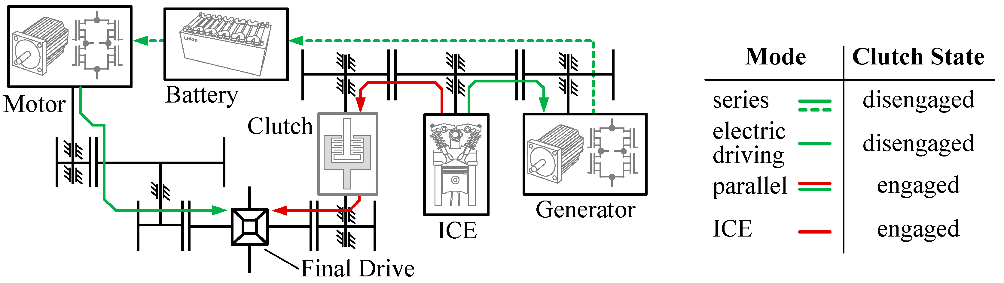
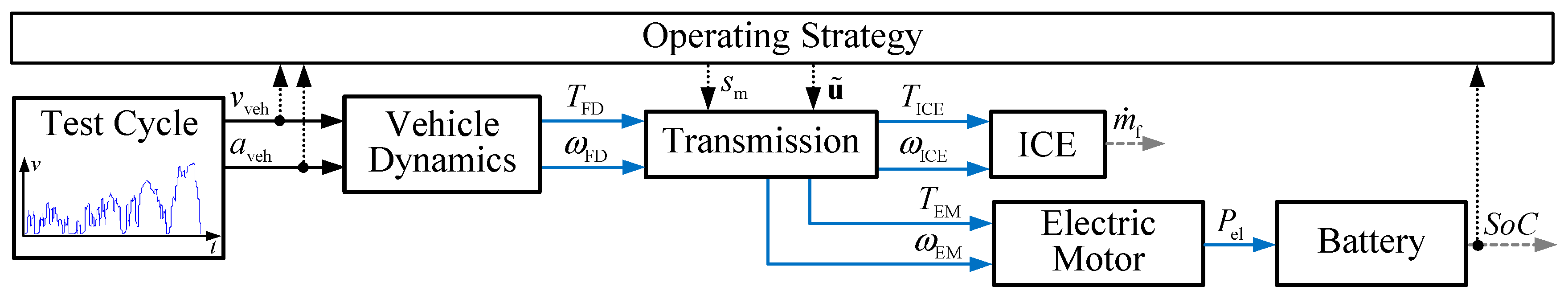
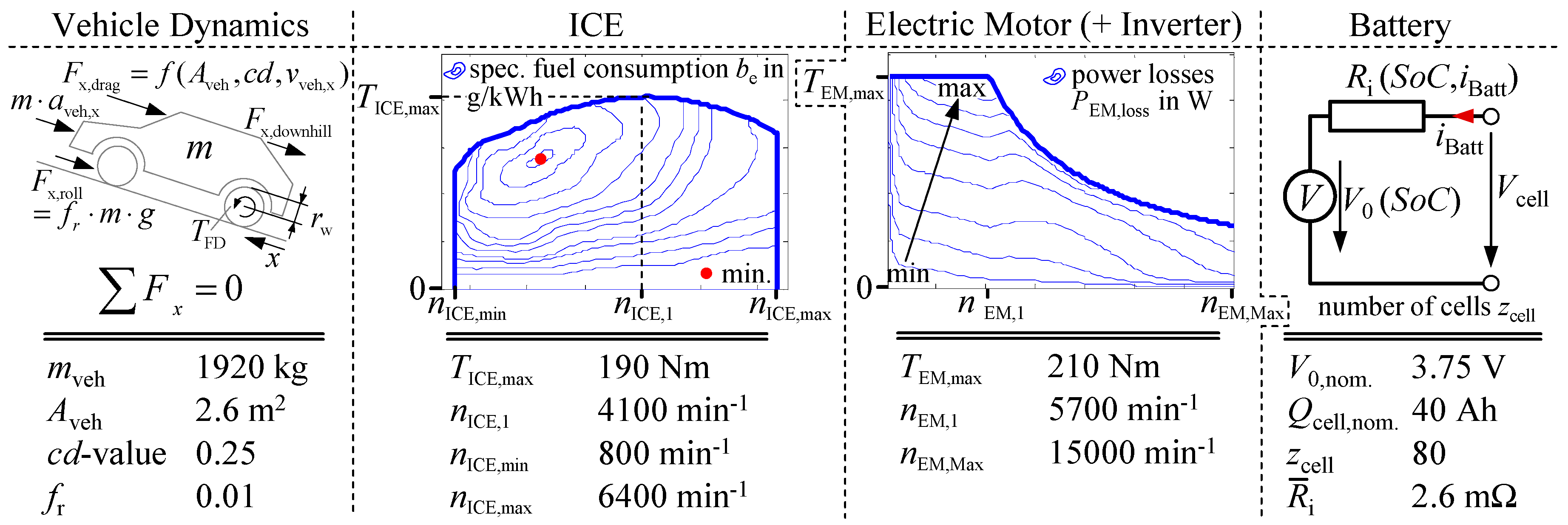
2. Powertrain Model
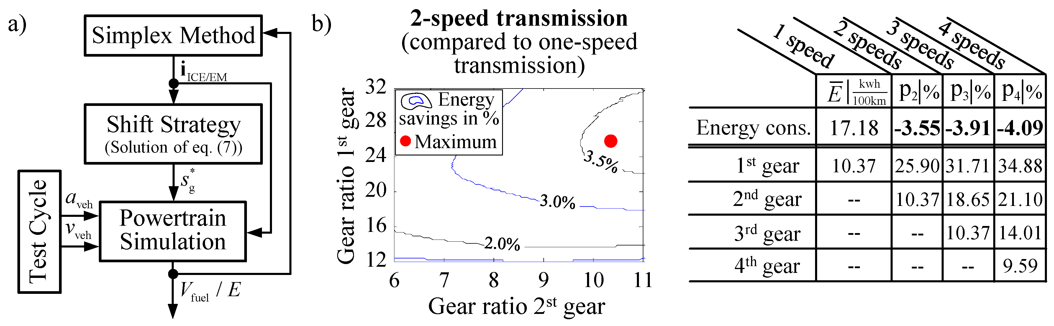
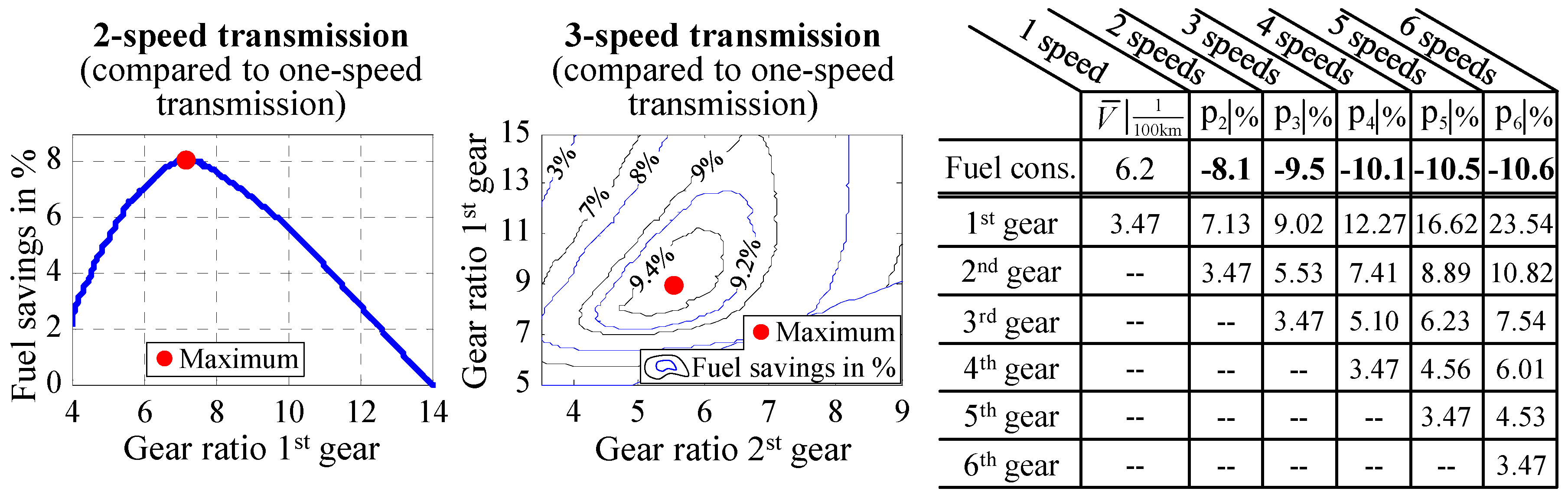
3. Optimization: Number of Speeds
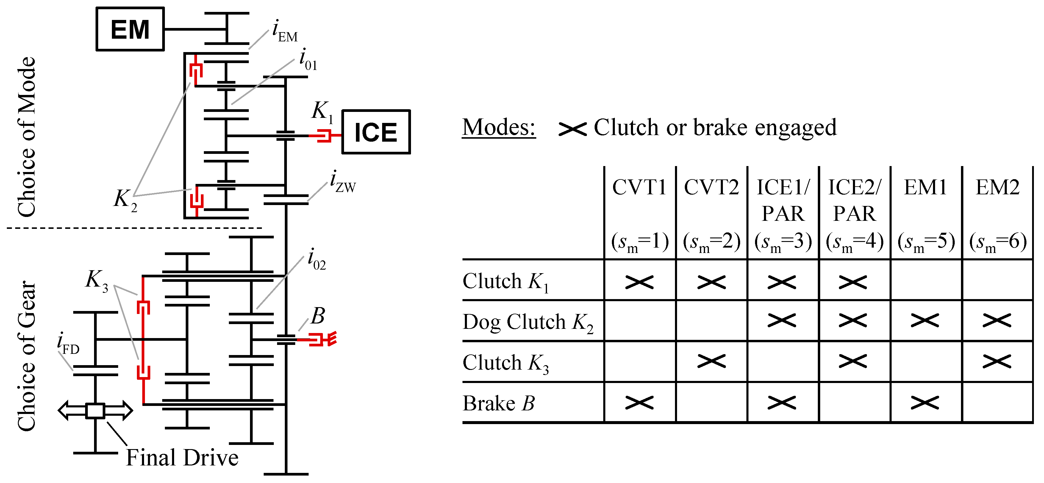
4. New Transmission Concept
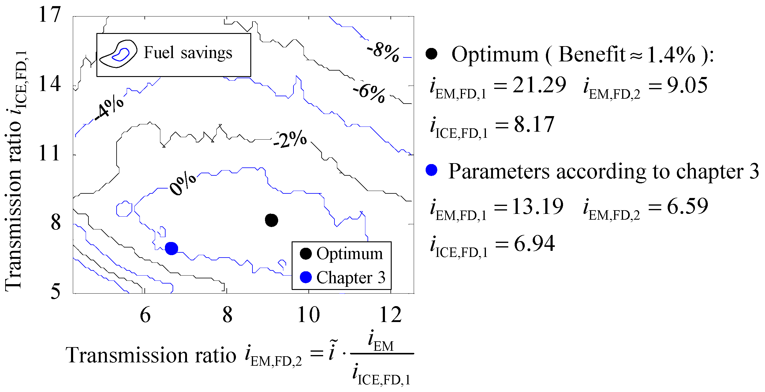
5. Optimization: Transmission Ratios
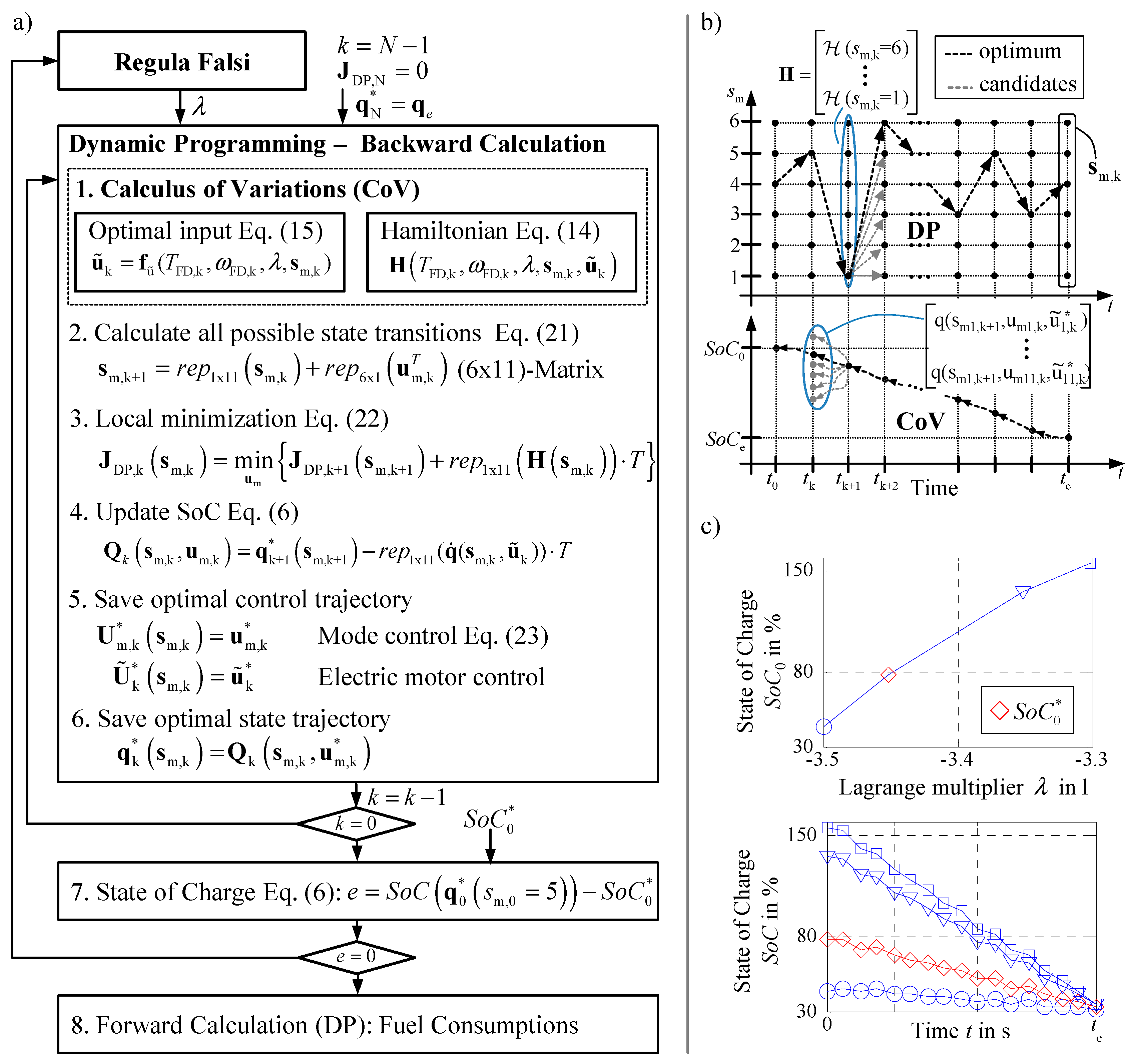
5.1. Calculus of Variations (CoV)
5.2. Dynamic Programming (DP)
5.3. DP and CoV Combined
5.4. Optimization Results
6. Concept Evaluation
7. Conclusions
Author Contributions
Funding
Acknowledgments
Conflicts of Interest
References
- Karbowski, D.; Pagerit, S.; Kwon, J.; Rousseau, A.; von Pechmann, K.-F.F. “Fair” Comparison of Powertrain Configurations for Plug-In Hybrid Operation Using Global Optimization; SAE Technical Paper 2009-01-1334; SAE: Detroit, MI, USA, 2009. [Google Scholar]
- Goppelt, G. Das DHT Hybridgetriebe neu definiert. ATZ Automobiltech. Z. 2016, 77, 8–15. [Google Scholar] [CrossRef]
- Taniguchi, M.; Yashiro, T.; Takizawa, K.; Baba, S.; Tsuchida, M.; Mizutani, T.; Endo, H. Development of New Hybrid Hybrid Transaxle for Compact-Class Vehicles; SAE Technical Paper, 2016-01-1163; SAE: Detroit, MI, USA, 2016. [Google Scholar]
- Conlon, B.M.; Blohm, T.; Harpster, M.; Holmes, A.; Tsuchida, M.; Mizutani, T.; Endo, H.; Kimura, H. The next Generation “Voltec” Extended Range EV Propulsion System. SAE Int. J. Altern. Powertrains 2015, 4, 248–259. [Google Scholar] [CrossRef]
- Gassmann, T.; Aikawa, M. GKN Multi-Mode eTransmission for Premium Hybrid Vehicles. In Proceedings of the 12th International CTI Symposium, Berlin, Germany, 2–5 December 2013. [Google Scholar]
- Geng, S.; Herber, S.; Hildebrandt, W.; Schulte, T. Powertrain Simulation and Optimization of a Multimode Transmission. In Proceedings of the FISITA World Automotive Congress, Busan, Korea, 26–30 September 2016. [Google Scholar]
- Geng, S.; Zubke, T.; Schulte, T. Model-Based Development of Transmission Concepts for Hybrid Electric Powertrains. In Proceedings of the IEEE Intelligent Vehicle Symposium, Redondo Beach, CA, USA, 11–14 June 2017. [Google Scholar]
- Silvas, E.; Hofman, T.; Murgovski, N.; Etman, P.; Steinbuch, M. Review of Optimization Strategies for System-Level Design in Hybrid Electric Vehicles. IEEE Trans. Veh. Technol. 2016, 66, 57–70. [Google Scholar] [CrossRef]
- Kang, C.; Lee, H.; Kim, J.; Park, Y.; Cha, S. Component Size and Gear Ratio Optimization in PHEV Powertrain. In Proceedings of the IEEE Intelligent Vehicle Symposium, Redondo Beach, CA, USA, 11–14 June 2017. [Google Scholar]
- Eghtessad, M. Optimale Antriebsstrangkonfigurationen für Elektrofahrzeuge. Ph.D. Thesis, University of Braunschweig, Braunschweig, Germany, 2014. [Google Scholar]
- Murgovski, N.; Johannesson, L.; Sjöberg, J.; Egardt, B. Component Sizing of a Plug-in Hybrid Electric Powertrain via Convex Optimization. Mechatronics 2012, 22, 106–120. [Google Scholar] [CrossRef]
- Kim, I.; Kim, H. Configuration Analysis of Plug-in Hybrid Systems using Global Optimization. World Electr. Veh. J. 2013, 6, 391–404. [Google Scholar] [CrossRef]
- Herber, S. PHEVplus: Effizienzsteigerndes DHT für Plug-In Hybridanwendungen. In Proceedings of the 17. Internationaler VDI-Kongress Getriebe in Fahrzeugen, Bonn, Germany, 5–6 July 2017. [Google Scholar]
- Markel, T.; Brooker, A.; Hendricks, T.; Johnson, V.; Kelly, K.; Kramer, B.; O’Keefe, M.; Sprik, S.; Wipke, K. ADVISOR: A Systems Analysis Tool for Advanced Vehicle Modeling. J. Power Sources 2002, 110, 255–266. [Google Scholar] [CrossRef]
- Geng, S.; Schulte, T. Real-Time Powertrain Models of Hybrid Electric Vehicles. SAE Int. J. Altern. Powertrains 2015, 46, 677–682. [Google Scholar] [CrossRef]
- Ngo, V.; Hofman, T.; Steinbruch, M.; Serrarens, A. Optimal Control of the Gearshift Command for Hybrid Electric Vehicles. IEEE Trans. Veh. Technol. 2012, 61, 3531–3543. [Google Scholar] [CrossRef]
- Naidu, D.S. Optimal Control Systems; Electrical Engineering Textbook Series; CRC Press: Boca Raton, FL, USA, 2003. [Google Scholar]
- Kim, N.; Rousseau, A. Sufficient conditions of optimal control based on Pontryagin’s minimum principle for use in hybrid electric vehicles. J. Autom. Eng. 2012, 226, 1160–1170. [Google Scholar] [CrossRef]
- Bertsekas, D.P. Dynamic Programming and Optimal Control Volume I; Athena Scientific: Belmont, MA, USA, 2005. [Google Scholar]


© 2018 by the authors. Licensee MDPI, Basel, Switzerland. This article is an open access article distributed under the terms and conditions of the Creative Commons Attribution (CC BY) license (http://creativecommons.org/licenses/by/4.0/).
Share and Cite
Geng, S.; Meier, A.; Schulte, T. Model-Based Optimization of a Plug-In Hybrid Electric Powertrain with Multimode Transmission. World Electr. Veh. J. 2018, 9, 12. https://doi.org/10.3390/wevj9010012
Geng S, Meier A, Schulte T. Model-Based Optimization of a Plug-In Hybrid Electric Powertrain with Multimode Transmission. World Electric Vehicle Journal. 2018; 9(1):12. https://doi.org/10.3390/wevj9010012
Chicago/Turabian StyleGeng, Stefan, Andreas Meier, and Thomas Schulte. 2018. "Model-Based Optimization of a Plug-In Hybrid Electric Powertrain with Multimode Transmission" World Electric Vehicle Journal 9, no. 1: 12. https://doi.org/10.3390/wevj9010012
APA StyleGeng, S., Meier, A., & Schulte, T. (2018). Model-Based Optimization of a Plug-In Hybrid Electric Powertrain with Multimode Transmission. World Electric Vehicle Journal, 9(1), 12. https://doi.org/10.3390/wevj9010012