Development of a Dual-Mode Measurement and Control System with Energy Feedback Optimization for a Retrofitted NEV Powertrain Dynamometer


Abstract
1. Introduction
2. System Architecture
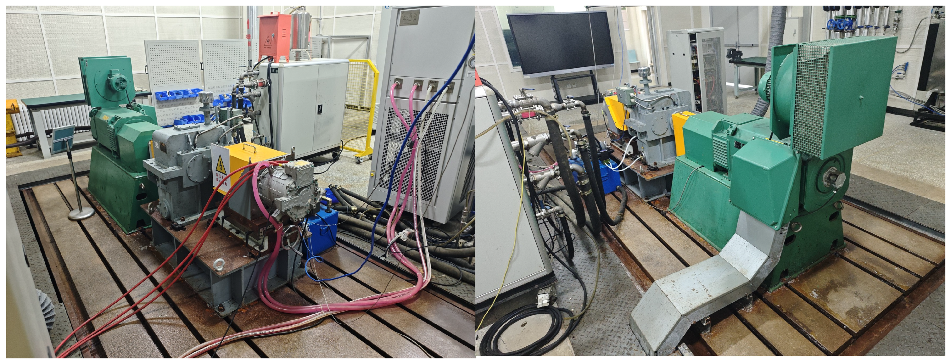
2.1. Hardware Platform
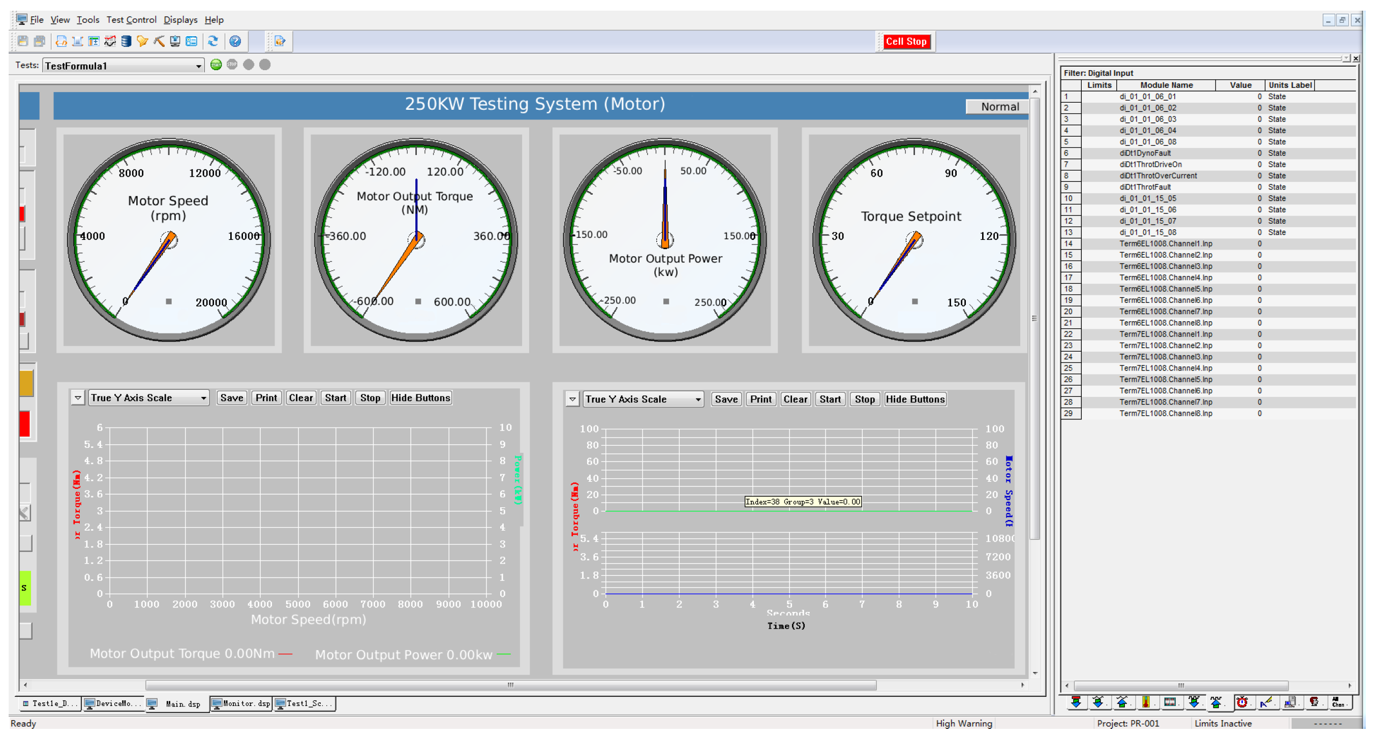
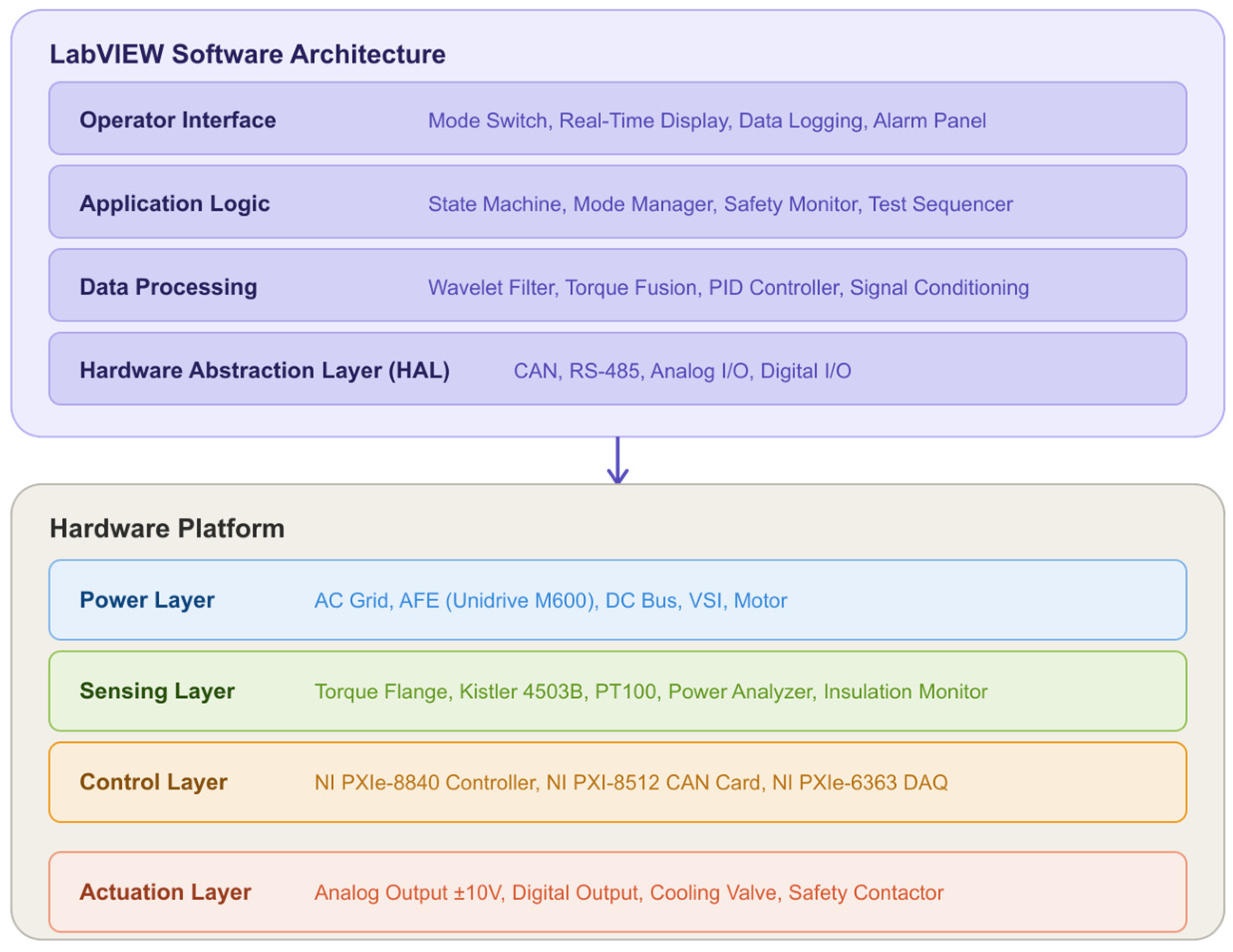
2.2. Software Architecture
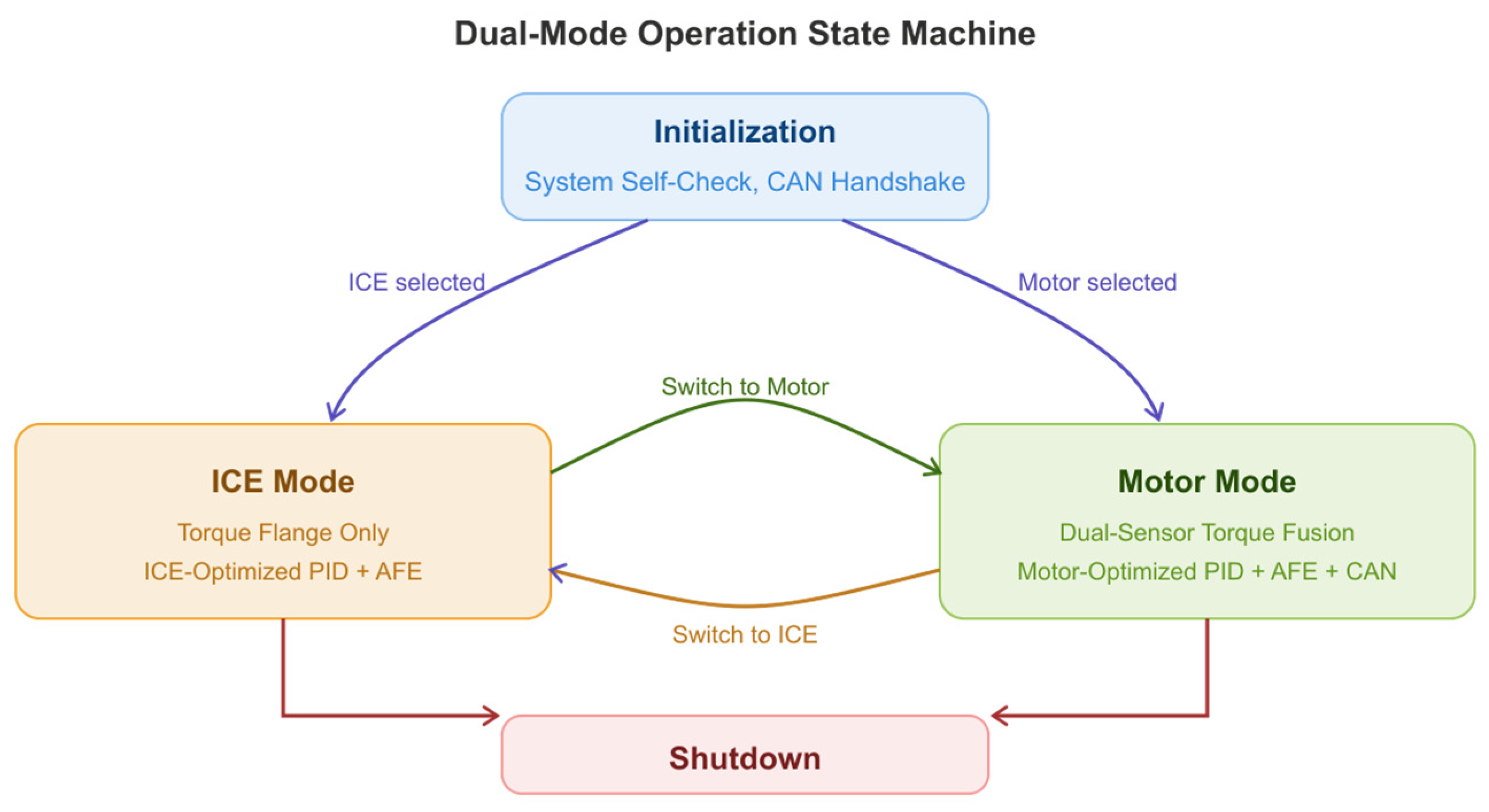
2.3. Dual-Mode Operation Logic
3. Key Technical Solutions
3.1. Cross-Mode Control Algorithm Migration
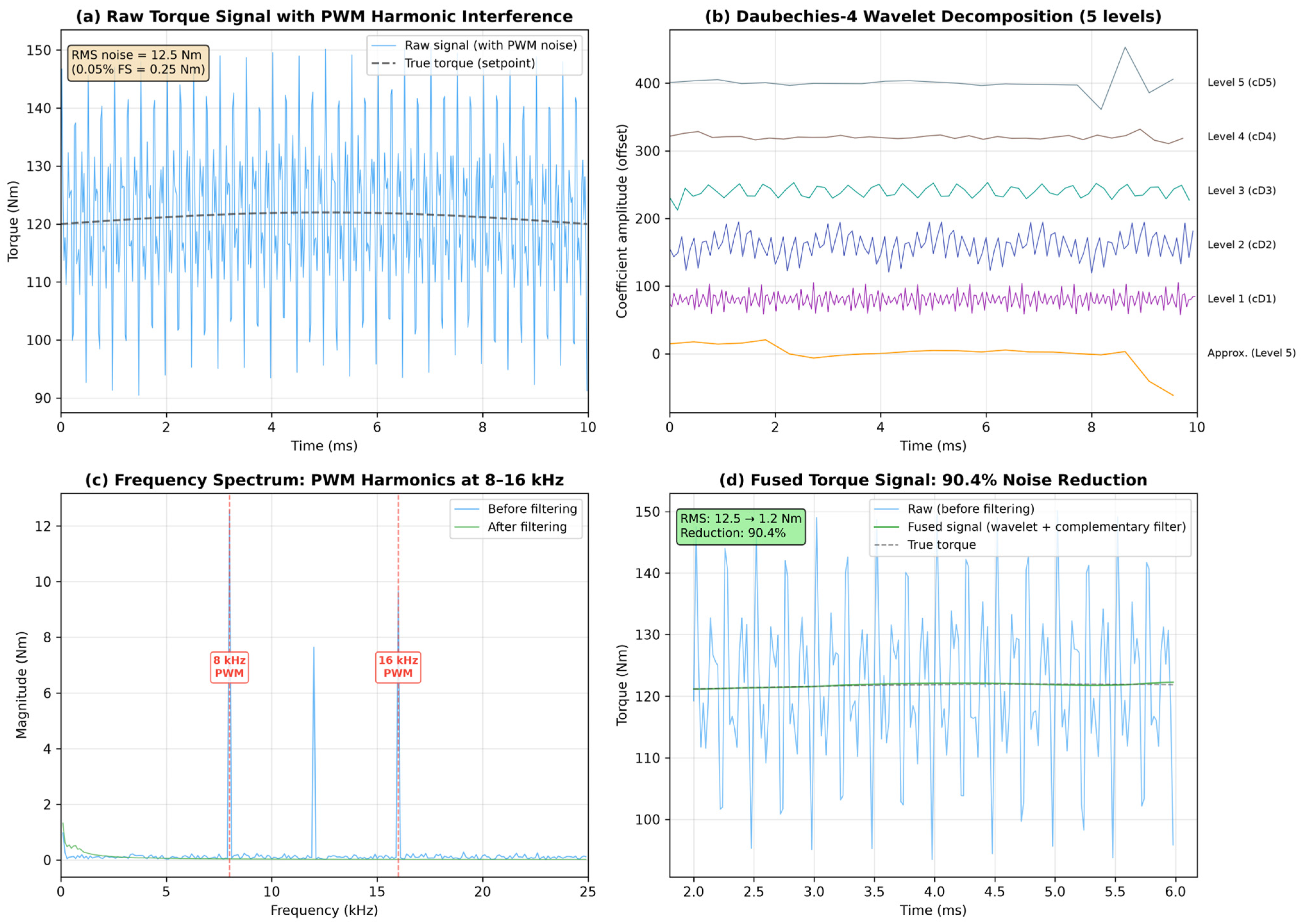
3.2. Multi-Source Signal Fusion and Precision Compensation
3.3. CAN Bus Communication Integration
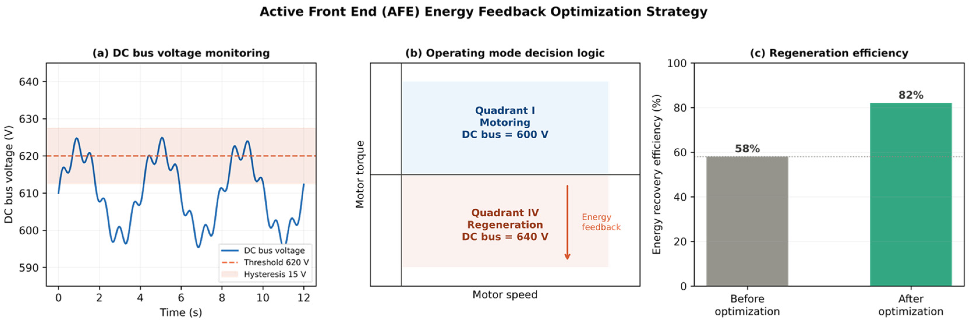
3.4. Energy Feedback System Optimization
3.5. Safety Interlock and Insulation Monitoring
4. Results and Discussion
4.1. Test Configuration
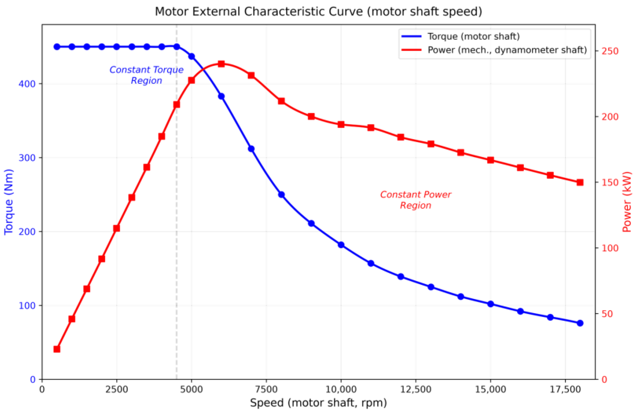
4.2. External Characteristic Test
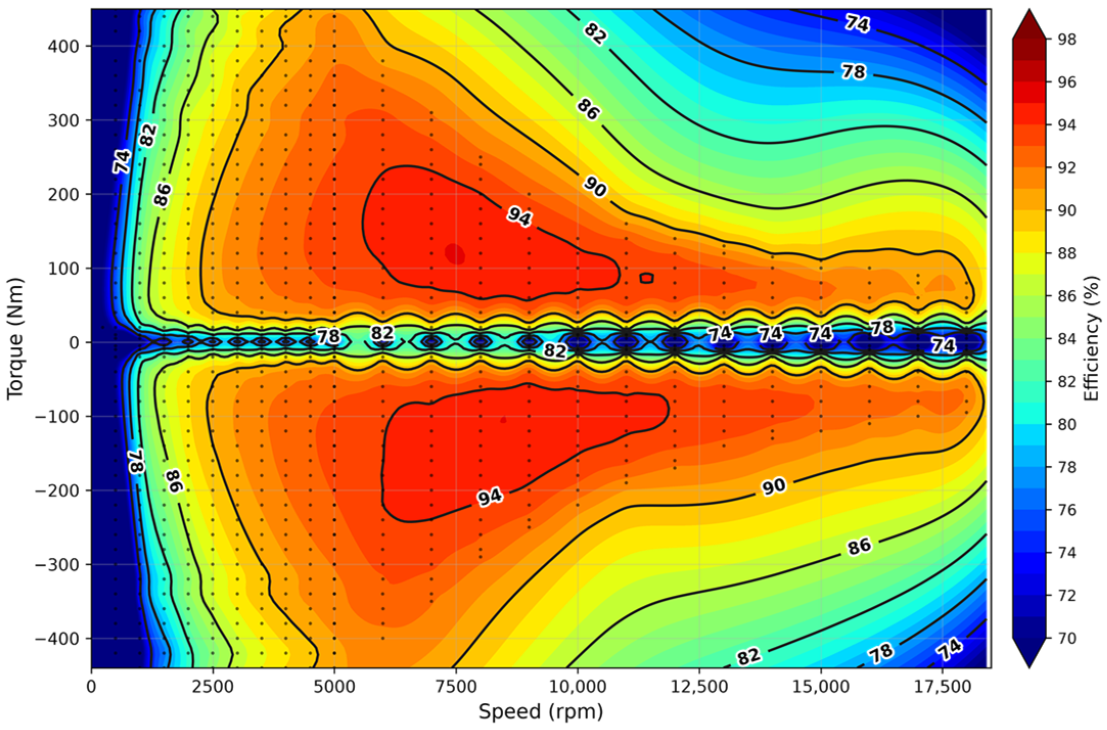
4.3. Efficiency MAP Generation
4.4. Temperature Rise Analysis
4.5. Insulation Monitoring Verification
4.6. System Performance Assessment
4.7. Educational Value
4.8. Limitations
5. Conclusions
- A dual-mode measurement and control system has been developed and validated on a retrofitted 250 kW test bench, addressing the key challenges that arise when extending ICE-era test infrastructure to support electric motor testing. The system integrates three core technical contributions: a gain-scheduled PID controller with inertia feedforward and bumpless mode switching for cross-mode control migration; a wavelet-based dual-sensor torque fusion method using complementary filtering; and an active front end (AFE) energy feedback optimization with quadrant-dependent DC bus voltage setpoints and dynamic regeneration thresholds.
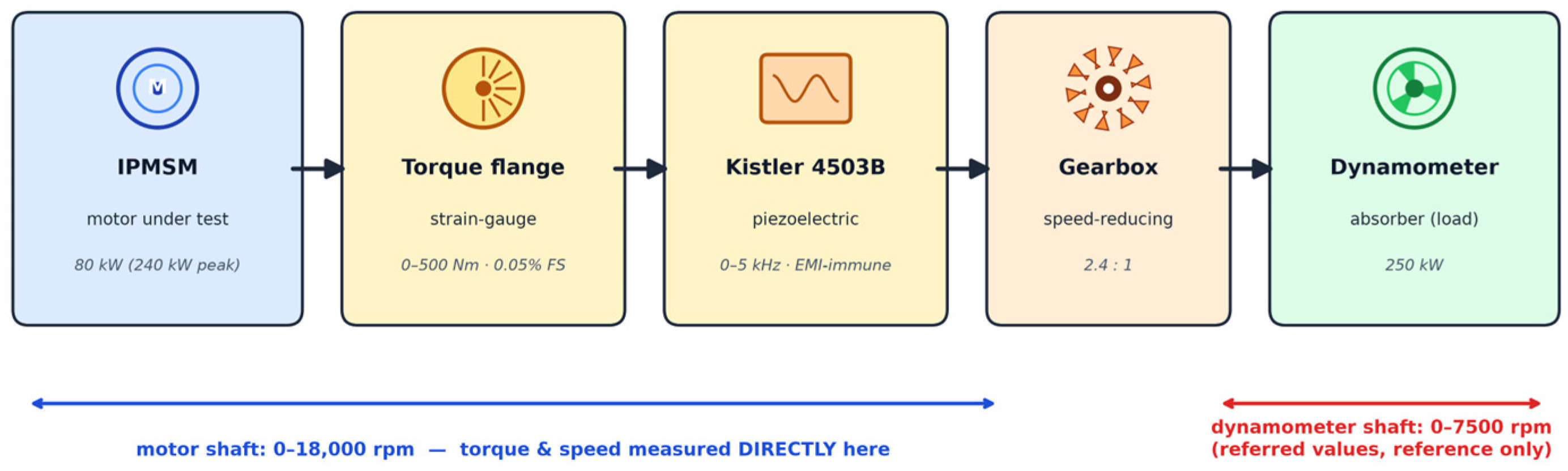
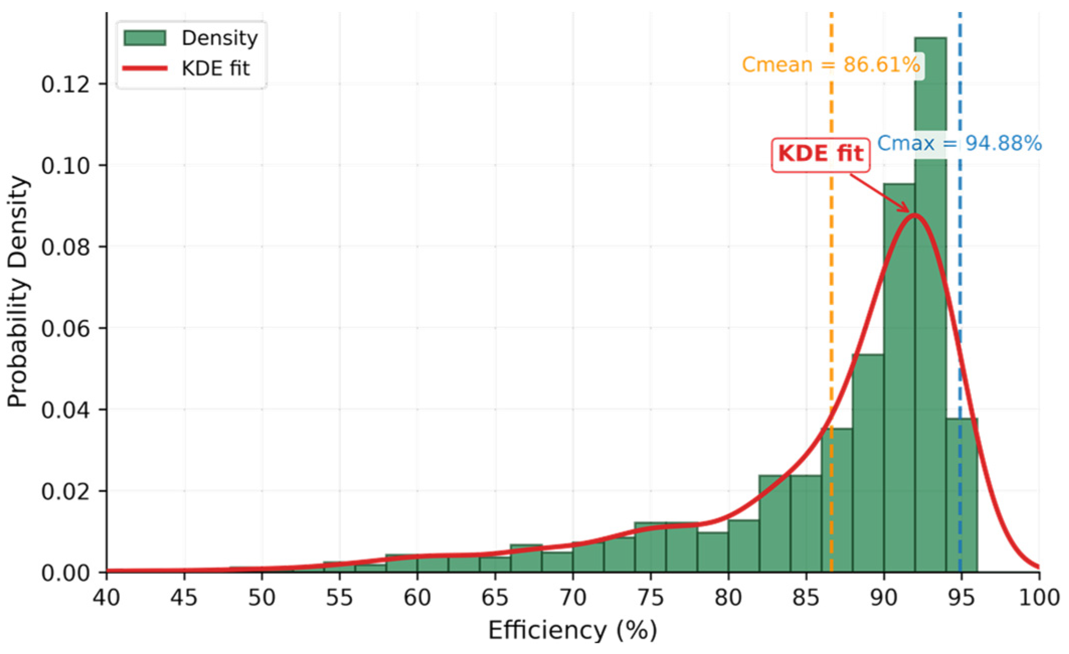
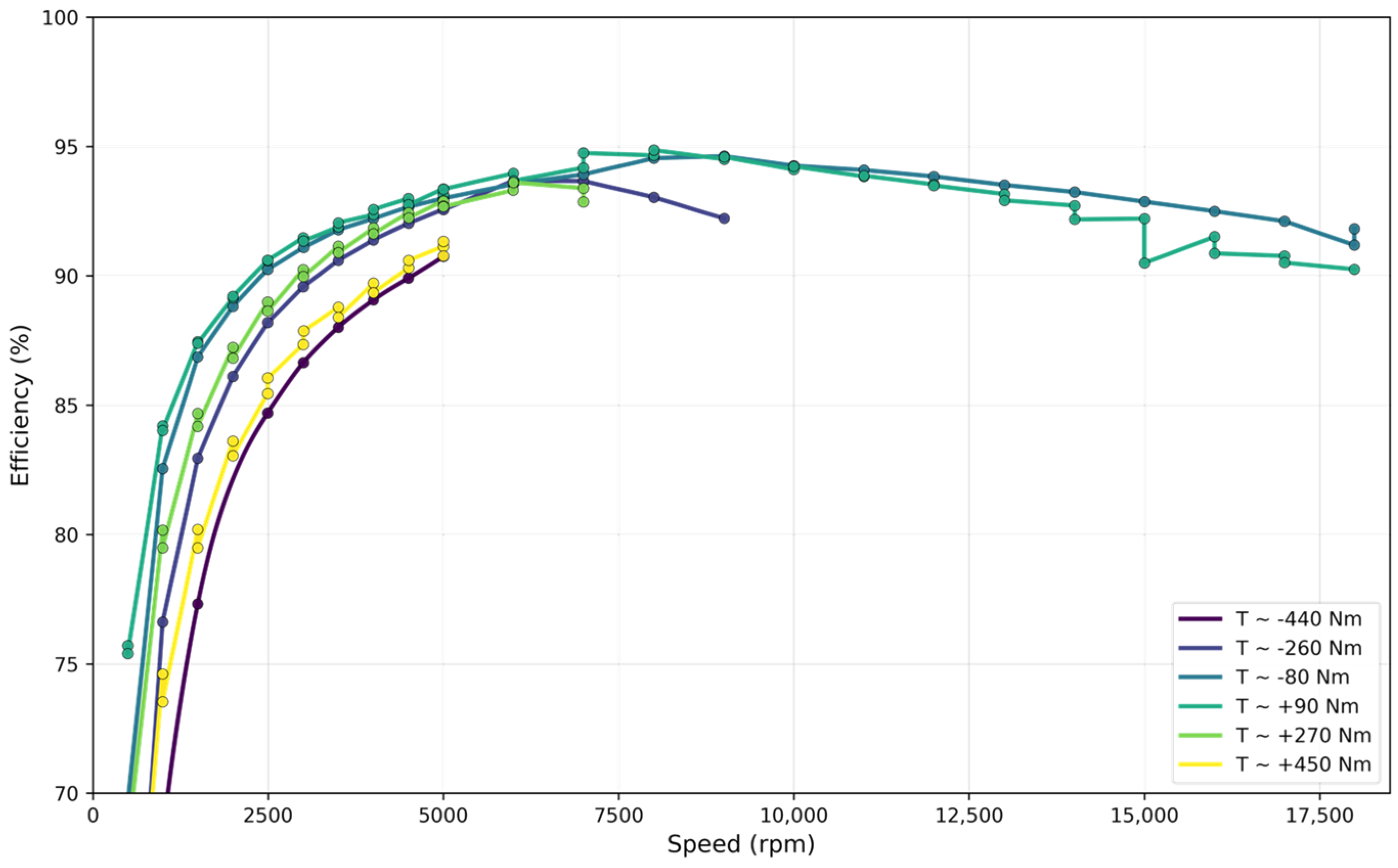
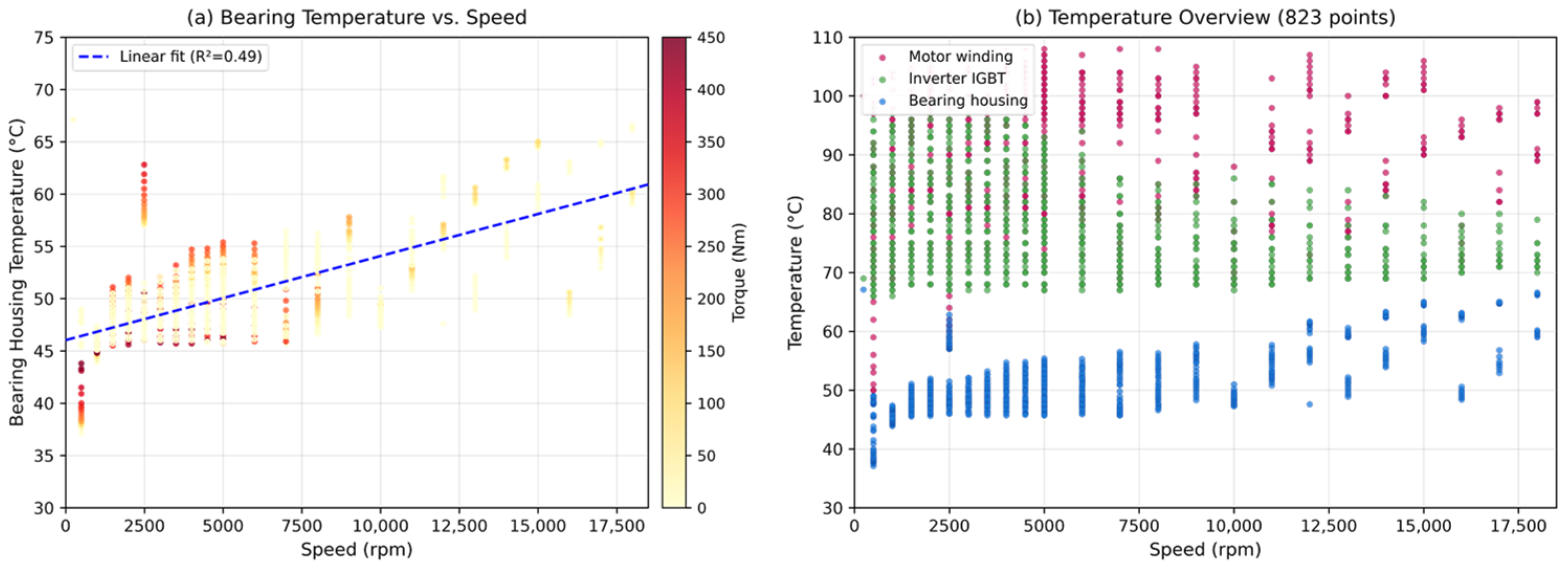
- Comprehensive validation was conducted on an 80 kW (240 kW peak) interior permanent magnet synchronous motor (IPMSM) across 823 steady-state operating points spanning the full torque-speed envelope. The external characteristic, efficiency MAP, energy recovery, and thermal measurements all confirmed that the system meets the motor’s specifications and operates within safe limits throughout the test campaign.
- The developed system provides a practical, cost-effective template for laboratories and vocational institutions seeking to modernize their powertrain testing capabilities while preserving existing investments in ICE testing infrastructure. The modular architecture and documented integration procedures enable adaptation to other dynamometer platforms with minimal re-engineering. Several limitations remain to be addressed in future research: the wavelet filter parameters were empirically tuned for the specific IPMSM and its 8–16 kHz PWM switching frequency, the CAN bus interface currently supports only one motor controller protocol, and validation was conducted on a single IPMSM type. Future work will focus on extending the wavelet fusion framework with automatic parameter adaptation for diverse PWM spectra, integrating additional motor controller communication protocols, and verifying the retrofit methodology on more motor topologies and dynamometer platforms.
Author Contributions
Funding
Data Availability Statement
Acknowledgments
Conflicts of Interest
Nomenclature
| Equation | Symbol | Unit | Description |
| (1) | — | Proportional gain | |
| — | Integral gain | ||
| — | Derivative gain | ||
| Nm | Feedforward torque term compensating gearbox inertia | ||
| kg·m2 | Total moment of inertia reflected to motor shaft (~0.25) | ||
| ms | Control loop sampling period (1 ms) | ||
| (2) | Nm | Final fused torque estimate (closed-loop and logging) | |
| — | Low-pass filter transfer function (unity DC gain) | ||
| — | High-pass filter transfer function (zero DC gain) | ||
| Nm | Low-bandwidth torque flange signal | ||
| Nm | Wavelet-denoised Kistler 4503B signal | ||
| (3) | — | Noise standard deviation at decomposition level j | |
| — | Number of wavelet coefficients at level j | ||
| — | Natural logarithm | ||
| — | Universal threshold (following [14]) | ||
| (4) | % | System efficiency (mech output/elec input) | |
| Nm | Average measured torque | ||
| rad/s | Angular velocity | ||
| V | DC bus voltage | ||
| A | DC bus current | ||
| Abbr. | — | Coefficient of determination | |
| — | Root mean square | ||
| — | Full scale |
References
- International Energy Agency. Global EV Outlook 2025; IEA: Paris, France, 2025. [Google Scholar]
- Schubert, M.; Oertel, H. A Motor-Inverter Test Bed for Investigation of Conducted Emissions under Electric Fault Conditions. In 2022 ESA Workshop on Aerospace EMC (Aerospace EMC); IEEE: Piscataway, NJ, USA, 2022. [Google Scholar]
- He, G. Design and Implementation of Electric Vehicle Drive Motor Test Platform; Chang’an University: Xi’an, China, 2023. [Google Scholar]
- Endress, T.; Bragard, M. Recording of Efficiency-Maps of Low-Power Electric Drive Systems Using a Flexible Matlab-Based Test Bench. In Proceedings of the 2017 IEEE 58th International Scientific Conference on Power and Electrical Engineering of Riga Technical University (RTUCON); IEEE: Riga, Latvia, 2017; pp. 1–5. [Google Scholar]
- Schupbach, R.M.; Balda, J.C. A Versatile Laboratory Test Bench for Developing Powertrains of Electric Vehicles. In Proceedings of the IEEE 56th Vehicular Technology Conference, Vancouver, BC, Canada, 24–28 September 2002; IEEE: Piscataway, NJ, USA, 2002; Volume 3, pp. 1666–1670. [Google Scholar]
- Boldea, I.; Tutelea, L.N.; Parsa, L.; Dorrell, D. Automotive Electric Propulsion Systems with Reduced or No Permanent Magnets: An Overview. IEEE Trans. Ind. Electron. 2014, 61, 5696–5711. [Google Scholar] [CrossRef] [Scilit]
- Dhote, V.P.; Lokhande, M.M.; Gupta, S.C. Test Bench Setup for Emulating Electric Vehicle On-Road Conditions. Energy Rep. 2023, 9, 218–227. [Google Scholar] [CrossRef] [Scilit]
- Roy, P.; Bandyopadhyay, A. Control of a Three-Level T-Type Inverter-Fed PMSM with Regenerative Braking Tested with Dynamometer Test Bench Emulation and EV Load. IEEE Trans. Transp. Electrif. 2025, 12, 487–498. [Google Scholar] [CrossRef] [Scilit]
- Veyrat Durbex, A.F.; Nachajon Schwartz, Y.; Tacca, H. Solutions for Torque and Speed Measurement on Electric Machine Controllers Test Benches. Elektron 2021, 5, 20–31. [Google Scholar] [CrossRef] [Scilit]
- Control Techniques. Unidrive M600 User Guide; Emerson Industrial Automation: Eden Prairie, MN, USA, 2015. [Google Scholar]
- National Instruments. LabVIEW 2020 Real-Time Module Help; National Instruments: Austin, TX, USA, 2020. [Google Scholar]
- Singh, R.; Kachhwaha, M.; Fulwani, D. Active Disturbance Rejection and Low-Speed Performance Enhancement in EV Drives Using ASISMC under Dynamic Load Conditions. CES Trans. Electr. Mach. Syst. 2025, 9, 463–472. [Google Scholar] [CrossRef] [Scilit]
- Daubechies, I. Ten Lectures on Wavelets; SIAM: Philadelphia, PA, USA, 1992. [Google Scholar]
- Donoho, D.L.; Johnstone, I.M. Adapting to Unknown Smoothness via Wavelet Shrinkage. J. Am. Stat. Assoc. 1995, 90, 1200–1224. [Google Scholar] [CrossRef]
- SAE J1939; Serial Control and Communications Heavy Duty Vehicle Network. SAE International: Warrendale, PA, USA, 2013.
- National Instruments. NI-XNET CAN Hardware and Software Manual; National Instruments: Austin, TX, USA, 2019. [Google Scholar]
- ISO 13849-1:2023; Safety of Machinery—Safety-Related Parts of Control Systems—Part 1: General Principles for Design. ISO: Geneva, Switzerland, 2023.
- GB/T 18488-2024; Drive Motor System for Electric Vehicles—Specifications. Standardization Administration of China: Beijing, China, 2024.
- Chang, S.-H.; Yeh, H.-Y. Optimal Efficiency and Automatic Current Commands Map Generator for an Interior Permanent Magnet Synchronous Motor in Electric Vehicles. Appl. Sci. 2025, 15, 9838. [Google Scholar] [CrossRef] [Scilit]
- Novak, M.; Novak, J. Test Setup with a Permanent Magnet Synchronous Machine for Efficiency Maps of an Electric Vehicle. In Proceedings of the 2018 23rd International Conference on Electrical Machines (ICEM 2018), Alexandroupoli, Greece, 3–6 September 2018; IEEE: Piscataway, NJ, USA, 2018; pp. 2471–2477. [Google Scholar]
- IEC 61557-8; Electrical Safety in Low Voltage Distribution Systems up to 1000 V a.c. and 1500 V d.c.—Equipment for Testing, Measuring or Monitoring of Protective Measures—Part 8: Insulation Monitoring Devices for IT Systems. International Electrotechnical Commission: Geneva, Switzerland, 2014.







| AFE Parameter | ICE Mode (Original) | Motor Mode (Optimized) |
|---|---|---|
| Regeneration trigger threshold | 650 V | 620 V |
| DC bus setpoint (motoring) | 650 V | 600 V |
| DC bus setpoint (regeneration) | 650 V | 640 V |
| AFE current limit (regeneration) | 80% of rated | 95% of rated |
| Energy recovery efficiency | 58% | 82% |
| Speed (rpm) | Torque (Nm) | Mechanical Power (kW) | System Efficiency (%) | Winding Temp (°C) |
|---|---|---|---|---|
| 500 | 450 | 22.9 | 58.8 | 102 |
| 1500 | 450 | 68.8 | 79.5 | 92 |
| 2500 | 450 | 114.9 | 86.0 | 75 |
| 3500 | 450 | 161.4 | 88.4 | 94 |
| 4500 | 450 | 209.2 | 90.3 | 92 |
| 6000 | 380 | 240.2 | 90.7 | 104 |
| 9000 | 200 | 200.0 | 92.8 | 103 |
| 12,000 | 140 | 184.3 | 91.1 | 94 |
| 15,000 | 110 | 166.8 | 90.1 | 106 |
| 18,000 | 80 | 149.9 | 90.3 | 91 |
| Statistic | Value |
|---|---|
| Mean efficiency | 86.61% |
| Standard deviation | 9.21% |
| Minimum efficiency | 40.36% |
| Maximum (peak) efficiency | 94.88% |
| Peak efficiency location | 7000 rpm, 120 Nm |
| Operating points with η > 90% | 434 (52.7%) |
| Area fraction with η > 90% (grid cells) | 63.4% |
| Area fraction with η > 90% (operating points) | 52.7% |
| Component | Sensor Type | Mean (°C) | Max (°C) | Min (°C) | Range (°C) |
|---|---|---|---|---|---|
| Motor winding | Embedded PT100 | 87.7 | 108.0 | 48.0 | 60.0 |
| Inverter IGBT | Internal NTC | 77.4 | 98.0 | 66.0 | 32.0 |
| Bearing housing | Surface PT100 | 50.6 | 67.1 | 37.1 | 30.0 |
Disclaimer/Publisher’s Note: The statements, opinions and data contained in all publications are solely those of the individual author(s) and contributor(s) and not of MDPI and/or the editor(s). MDPI and/or the editor(s) disclaim responsibility for any injury to people or property resulting from any ideas, methods, instructions or products referred to in the content. |
© 2026 by the authors. Published by MDPI on behalf of the World Electric Vehicle Association. Licensee MDPI, Basel, Switzerland. This article is an open access article distributed under the terms and conditions of the Creative Commons Attribution (CC BY) license.
Share and Cite
Chen, Z.; Wang, Z. Development of a Dual-Mode Measurement and Control System with Energy Feedback Optimization for a Retrofitted NEV Powertrain Dynamometer. World Electr. Veh. J. 2026, 17, 476. https://doi.org/10.3390/wevj17090476
Chen Z, Wang Z. Development of a Dual-Mode Measurement and Control System with Energy Feedback Optimization for a Retrofitted NEV Powertrain Dynamometer. World Electric Vehicle Journal. 2026; 17(9):476. https://doi.org/10.3390/wevj17090476
Chicago/Turabian StyleChen, Zimou, and Zhe Wang. 2026. "Development of a Dual-Mode Measurement and Control System with Energy Feedback Optimization for a Retrofitted NEV Powertrain Dynamometer" World Electric Vehicle Journal 17, no. 9: 476. https://doi.org/10.3390/wevj17090476
APA StyleChen, Z., & Wang, Z. (2026). Development of a Dual-Mode Measurement and Control System with Energy Feedback Optimization for a Retrofitted NEV Powertrain Dynamometer. World Electric Vehicle Journal, 17(9), 476. https://doi.org/10.3390/wevj17090476