1. Introduction
Four-wheel steering (4WS) technology has significantly improved vehicle handling stability and driving safety while effectively overcoming the limitations of conventional vehicles, such as poor steering agility at low speeds and insufficient steering stability at high speeds [
1]. To improve the trajectory tracking accuracy and driving stability of autonomous vehicles, Li et al. [
2] proposed an adaptive model predictive control (MPC) algorithm considering the road adhesion coefficient, in which the cost function of the MPC controller is adaptively adjusted according to the lateral tracking error and road curvature. Jin et al. [
3] developed an enhanced MPC strategy based on B-spline approximation and state-dependent referencing (BS-MPC), where the control input sequence is approximated using quasi-uniform B-spline curves, thereby significantly reducing the number of optimization variables and improving computational efficiency. Li et al. [
4] proposed a multi-parameter optimized MPC-based trajectory tracking strategy to reduce the large tracking errors encountered in high-curvature paths during autonomous vehicle lateral control. Feng et al. [
5] introduced an adaptive MPC controller based on a preview PID controller and the deep deterministic policy gradient (DDPG) algorithm to achieve adaptive controller parameter tuning, thereby significantly improving the adaptability of conventional MPC to time-varying conditions while enhancing tracking accuracy and stability.
To further improve the overall control performance, Liu et al. [
6] presents a fuzzy explicit model predictive control(EMPC) for trajectory tracking of the autonomous vehicle.The fuzzy EMPC is designed by solving the adaptive offline optimization instead of online optimization calculated in the original model predictive control(MPC). Chen et al. [
7] to increase safety in path planning and improve tracking performance, an path planning and tracking scheme based on the safe LC area algorithm and the optimized variable horizon parameter model predictive control (MPC) is proposed. Guan [
8] investigated trajectory tracking control for autonomous vehicles by establishing vehicle dynamic and steering models and developing coordinated lateral and longitudinal tracking strategies. Considering the strong coupling between lateral and longitudinal dynamics during emergency obstacle avoidance, Li et al. [
9] designed a centralized MPC controller; however, the high-dimensional optimization matrices resulted in considerable computational complexity. Zhang et al. [
10] enhanced the robustness of four-wheel independent steering (4WIS) vehicles under uncertain internal control parameters by improving the Tube-based robust MPC (Tube-RMPC) approach.
To enhance the adaptability of MPC, Lin et al. [
11] incorporated reinforcement learning to compensate for errors caused by unknown vehicle dynamics and adjusted the MPC weighting matrices according to trajectory tracking errors. Although the proposed method exhibited superior disturbance rejection and dynamic performance compared with conventional MPC, discrepancies remained between simulation and experimental results. Wu et al. [
12] investigated the influence of the MPC prediction horizon on the trajectory tracking stability and accuracy of four-wheel independent drive (4WID) vehicles and proposed a variable-horizon path tracking and stability control strategy. Gao et al. [
13] developed a hierarchical control framework for 4WID vehicles consisting of a control layer, a stability layer, and a torque allocation layer, where a genetic particle swarm optimization algorithm and fractional-order sliding mode control were employed to enhance vehicle stability. Wu et al. [
14] proposed an adaptive prediction horizon MPC strategy to improve the trajectory tracking accuracy of unmanned vehicles under different driving speeds by optimizing the conventional fixed-horizon MPC controller. Wang et al. [
15] addressed the difficulty of selecting suitable weighting matrices in MPC-based path tracking by proposing a genetic particle swarm optimization MPC algorithm, which effectively improved computational efficiency and tracking accuracy.
In an automated distributed-drive electric vehicle, the trajectory tracking controller must coordinate the steering system and the independently controlled electric-wheel torques. Compared with conventional centralized powertrains, in-wheel motors provide rapid and independent wheel torque regulation, allowing a direct yaw moment to be generated through differential torque control. Therefore, the distributed electric powertrain provides an important actuator basis for integrated trajectory tracking and vehicle stability control. At present, two mainstream control strategies are widely adopted for lower-layer torque allocation controllers. The traditional distributed torque allocation strategy [
16,
17] first distributes the driving torque between the left and right sides according to the optimal yaw moment and the desired driving force, and subsequently allocates the torque between the front and rear axles by considering objectives such as maximizing tire utilization and minimizing energy consumption. To fully exploit the differential steering capability of distributed drive electric vehicles (DDEVs), different front–rear torque distribution coefficients are generally assigned to the left and right sides. To ensure vehicle stability under limit driving conditions, several studies have proposed a single-stage torque allocation strategy [
18,
19], in which the desired driving force and the optimal direct yaw moment (DYM) are incorporated into the objective function as soft constraints. Meanwhile, objectives such as maximizing tire utilization and minimizing energy consumption are simultaneously considered. By assigning different weighting factors, the optimization problem is formulated as a quadratic programming (QP) problem and solved accordingly. In Ref. [
20], a weighting factor tuning scheme was proposed; however, it guarantees vehicle stability only by constraining the lateral acceleration, which is insufficient to ensure the safety of DDEVs. Since stability and maneuverability are inherently conflicting objectives under limit handling conditions, it is difficult to achieve an effective trade-off using a single torque allocation strategy [
21,
22]. To further improve vehicle stability, Li et al. [
23] integrated four-wheel steering with direct yaw moment control (DYC) using the MPC framework, thereby enhancing vehicle safety under extreme driving conditions. Zhang et al. [
24] proposes a path following control framework for 4WIS vehicles that explicitly considers variable adhesion conditions of intermittent ice-snow roads. Kou et al. [
25] adopted LQR for both four-wheel steering and yaw moment control; however, the interaction between the two controllers was not taken into consideration. Recent studies have also proposed advanced sliding mode control strategies with disturbance observers to improve robustness against disturbances and model uncertainties [
26,
27]. Different from these studies, which mainly focus on disturbance rejection through robust nonlinear control design, this study concentrates on online parameter reconfiguration of an MPC framework by simultaneously adapting the weighting matrices and prediction/control horizons while coordinating four-wheel steering, DYC, and torque allocation.
Although adaptive MPC, variable-horizon MPC, four-wheel-steering control, and direct yaw moment control have been extensively investigated, several limitations remain. First, most adaptive MPC strategies mainly adjust the weighting matrices while retaining fixed prediction and control horizons, whereas variable-horizon strategies generally focus on horizon adjustment without simultaneously adapting the weighting matrices. Moreover, existing variable-horizon methods commonly adjust only the prediction horizon or determine the horizon according to a limited number of indicators, without jointly reconfiguring the prediction and control horizons while considering tracking performance, error evolution, control effort, and horizon coupling constraints. Second, previous 4WS and DYC studies mainly focus on coordinating steering and yaw moment control, but the controller parameters and horizons generally remain fixed under varying operating conditions. Third, existing torque allocation methods usually focus on yaw moment tracking, tire utilization, or energy consumption, with insufficient coordination between online upper-layer MPC reconfiguration and lower-layer tire-load-dependent torque allocation.
Therefore, the unresolved problem is not the individual implementation of adaptive weighting, variable horizons, 4WS, DYC, or torque allocation, but their coordinated integration into an online parameter-reconfigured hierarchical architecture in which the MPC weighting matrices and both horizons are adjusted simultaneously and the resulting control demands are realized through tire-load-aware torque allocation. Although advanced control methods such as sliding mode control (SMC) have demonstrated strong robustness against parameter uncertainties and external disturbances, they generally require careful parameter tuning and may suffer from chattering issues. In contrast, the proposed adaptive MPC framework explicitly handles multi-variable constraints while simultaneously optimizing steering and yaw moment control through online parameter reconfiguration.
Conventional model predictive control (MPC) strategies suffer from degraded trajectory tracking accuracy when large tracking errors occur, owing to the fixed weighting matrices in the cost function and the constant prediction and control horizons. To achieve higher tracking accuracy while improving vehicle handling stability, an improved hierarchical control strategy is proposed. At the upper control layer, an enhanced MPC algorithm is developed for trajectory tracking, whereas the lower control layer performs optimal torque allocation by considering the tire load ratio and vertical tire loads. The proposed integrated control strategy employs a fuzzy adaptive control algorithm to adjust the weighting matrices of the MPC cost function online. Furthermore, an adaptive prediction and control horizon adjustment (APCHA) strategy is incorporated to adaptively tune the prediction and control horizons, thereby overcoming the limited adaptability of conventional MPC caused by fixed weighting parameters and fixed horizons under varying driving conditions. Finally, comparative simulations are conducted with a conventional front-wheel steering (FWS) vehicle and a four-wheel steering (4WS) vehicle using the conventional MPC strategy to validate the effectiveness and superiority of the proposed approach.
This study develops an online parameter-reconfigured hierarchical control strategy for trajectory tracking and stability control of distributed-drive four-wheel-steering vehicles. The main contributions are summarized as follows:
- (1)
A coordinated hierarchical control framework is proposed that integrates online parameter-reconfigured MPC, four-wheel steering, direct yaw moment control, and torque allocation for distributed-drive vehicles;
- (2)
An online parameter reconfiguration strategy is developed to simultaneously adjust the weighting matrices and the prediction/control horizons according to the vehicle operating conditions, thereby improving the adaptability of the MPC controller;
- (3)
A comparative ablation study is conducted to quantify the individual contributions of the DYC module and the proposed torque allocation strategy, demonstrating that the performance improvement results from the coordinated design rather than the simple combination of existing modules.
2. Vehicle Dynamics Model
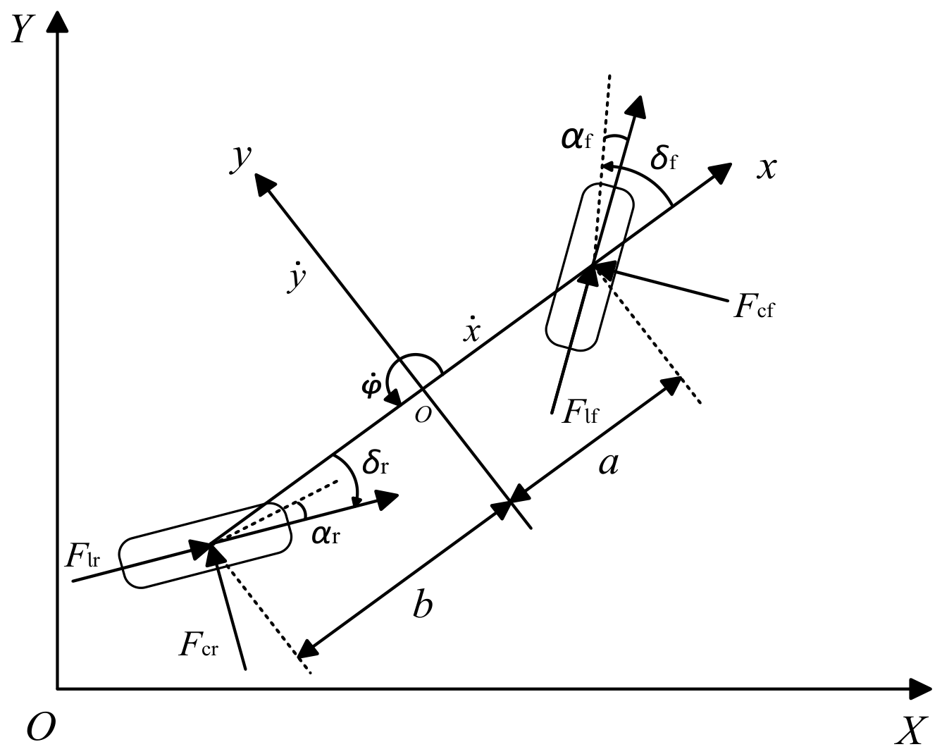
To reduce the computational burden of the controller while maintaining satisfactory control accuracy, a three-degree-of-freedom vehicle dynamics model is adopted for the design of the lateral motion controller, as shown in
Figure 1. In
Figure 1,
and
denote the lateral tire forces of the front and rear wheels, respectively;
and
denote the longitudinal tire forces of the front and rear wheels, respectively;
and
represent the front and rear steering angles, respectively;
and
are the distances from the vehicle center of gravity to the front and rear axles, respectively; and
and
denote the front and rear tire slip angles, respectively.
To establish a computationally efficient prediction model for the proposed MPC controller, the following assumptions are adopted:
- (1)
The vehicle body is regarded as a rigid body moving on a flat and level road. Only longitudinal, lateral, and yaw motions are considered, whereas roll, pitch, heave, and suspension dynamics are neglected.
- (2)
The four-wheel vehicle is represented by an equivalent single-track model. The left and right tires on each axle are assumed to have identical characteristics, and their forces are combined at the center of the corresponding axle.
- (3)
The tire slip angles, steering angles, and slip ratios are assumed to remain sufficiently small within the normal handling region. Therefore, the tire forces are approximated using linear tire characteristics, with the longitudinal and lateral tire forces proportional to the slip ratios and slip angles, respectively.
- (4)
The vehicle mass, yaw moment of inertia, axle distances, and nominal tire stiffness parameters are assumed to be known and constant during each simulation.
- (5)
The longitudinal velocity is not assumed to be constant throughout the entire maneuver. It is measured or updated at each sampling instant and treated as a known, slowly varying parameter during the local linearization and prediction process. A minimum longitudinal velocity threshold is imposed to avoid numerical singularities in the tire slip angle calculation.
- (6)
Aerodynamic forces, road bank and road slope effects, steering system dynamics, and external disturbances are neglected in the prediction model. Their combined influence is represented by the model mismatch between the simplified MPC model and the high-fidelity CarSim vehicle model.
The adopted three-degree-of-freedom model is intended for normal-to-moderately aggressive handling conditions in which the tire forces remain predominantly within the linear operating region and the vehicle states do not approach severe sideslip or tire force saturation. The model is therefore suitable for trajectory tracking control under the medium-speed/low-adhesion and high-speed/medium-adhesion conditions considered in this study, provided that the resulting tire slip angles and tire force utilization remain within the validated range. It is not expected to accurately represent extreme limit-handling conditions involving large tire slip angles, severe combined-slip saturation, wheel lift, or pronounced roll and pitch motions. Under such conditions, a nonlinear tire model and a higher-degree-of-freedom prediction model would be required. Although the prediction model adopts a linear tire representation, the controller is implemented in a receding-horizon manner using vehicle state feedback obtained from the high-fidelity CarSim model. Therefore, the prediction error introduced by tire nonlinearities is corrected at every sampling instant, preventing long-term error accumulation. Under the medium-speed/low-adhesion and high-speed/medium-adhesion scenarios considered in this study, the tire operating points remain predominantly within the quasi-linear region, and the resulting model mismatch has only a limited influence on trajectory tracking performance. As the vehicle approaches the tire adhesion limit, prediction accuracy inevitably decreases due to tire force saturation and combined slip effects. Nevertheless, the receding-horizon implementation with real-time state feedback partially compensates for the prediction errors introduced by the simplified model, allowing satisfactory tracking performance to be maintained under the two tested operating conditions.
The dynamic equations of the four-wheel steering (4WS) vehicle are expressed as follows:
where
and
are the vehicle velocities along the
and
axes in the global coordinate system, respectively;
and
are the longitudinal and lateral velocities along the
and
axes in the vehicle coordinate system, respectively;
is the total mass of the four-wheel steering vehicle;
and
denote the cornering stiffnesses of the front and rear tires, respectively;
and
represent the longitudinal stiffnesses of the front and rear tires, respectively;
and
are the slip ratios of the front and rear tires, respectively;
is the additional yaw moment;
and
denote the longitudinal and lateral accelerations along the
and
axes of the vehicle coordinate system, respectively; and
is the vehicle yaw rate.
3. Integrated Control Strategy
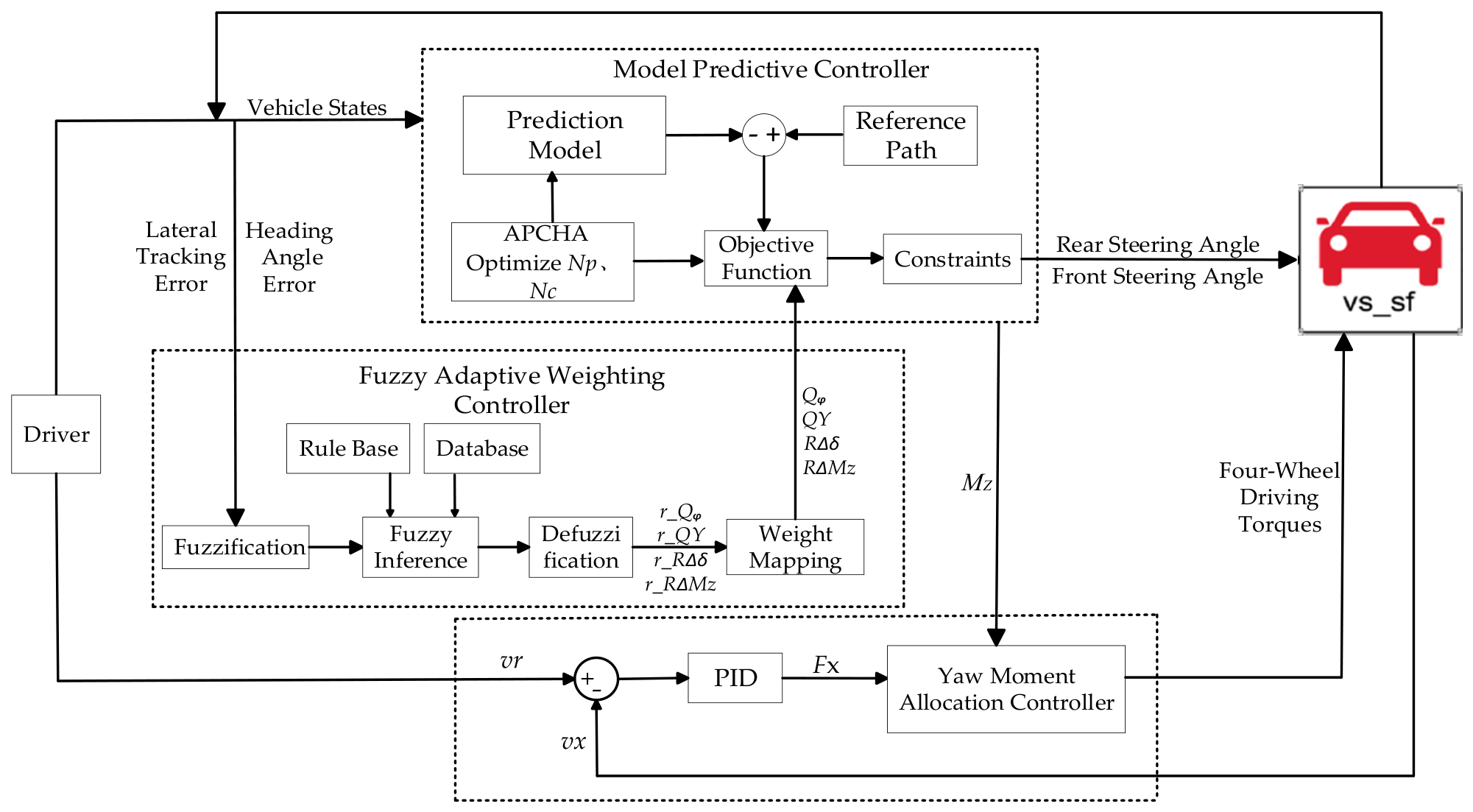
The proposed adaptive model predictive control (MPC) and direct yaw moment control (DYC)-based integrated control strategy is illustrated in
Figure 2. The vehicle states obtained from the CarSim model are first fed into the MPC controller, which calculates the front and rear steering angles as well as the additional yaw moment. Meanwhile, an adaptive prediction and control horizon adjustment (APCHA) strategy is incorporated to adjust the prediction and control horizons online. A fuzzy adaptive weighting controller is designed to take the lateral tracking error and heading angle error as inputs, enabling the online optimization of the MPC weighting matrices. The total driving torque is generated by a PID controller based on the deviation between the actual vehicle speed and the desired speed. Subsequently, the optimal torque allocation strategy determines the torque commands for the four in-wheel motors according to the additional yaw moment and the total driving torque while considering the tire load ratio and vertical tire loads as optimization constraints. Finally, the calculated front and rear steering angles together with the four-wheel driving torques are fed back to the CarSim vehicle model, enabling the vehicle states to track the desired reference states and thereby achieving stable vehicle motion control.
3.1. Model Predictive Control
In this section, a four-wheel steering controller for autonomous vehicles is developed based on model predictive control and fuzzy control theory. In addition, an adaptive prediction and control horizon adjustment strategy is developed. Exploiting the receding-horizon characteristics of MPC, the proposed APCHA strategy dynamically adjusts the and online at each control cycle by comprehensively considering three key indicators; namely, the integrated tracking error, the error variation rate, and the control input variation rate. Furthermore, engineering constraints, including horizon coupling and step size constraints, are incorporated to regulate the variation and dimensions of the prediction and control horizons while maintaining trajectory tracking performance and control stability. Moreover, a fuzzy adaptive weighting controller is introduced to adaptively tune the weighting matrices of the MPC cost function, thereby improving the online adjustment capability and control performance of the conventional MPC algorithm in response to variations in the tracking state.
3.1.1. Model Linearization and Discretization
Equation (1) can be rewritten in the following state-space form:
In Equation (2),
is the system state variable;
is the system control variable; and
is the derivative of the state variable.
The nonlinear vehicle dynamics model needs to be linearized. Therefore, Equation (2) is expanded using the Taylor series at time t, and the following linear time-varying equation is obtained:
where
and
denote the Jacobian matrices of the linearized nonlinear vehicle model evaluated at the current operating point.
Equation (3) is discretized using the forward Euler method, and the resulting discrete-time state-space model can be expressed as follows:
where
and
are the system coefficient matrices,
,
, and
is the sampling period.
In this study, the sampling period is selected as T = 0.01 s, which is consistent with the controller execution period adopted in the CarSim–Simulink co-simulation platform. The CarSim–Simulink co-simulation platform based on CarSim 2020.0 and MATLAB/Simulink R2023b was used. A smaller sampling period improves prediction accuracy but increases the computational burden of online optimization, whereas a larger sampling period may deteriorate the prediction accuracy. Therefore, T = 0.01 s is selected as a compromise. Since the selected sampling period is sufficiently small relative to the vehicle lateral dynamics, the forward Euler discretization introduces only negligible discretization errors while retaining a simpler numerical implementation than higher-order discretization methods.
3.1.2. Prediction Equation
During the trajectory tracking process, the future vehicle behavior over the specified prediction horizon is predicted. The optimal control input for the next sampling instant is obtained by minimizing the error between the predicted variables and the reference variables while satisfying various system constraints. Accordingly, the augmented state-space model is formulated as shown in Equation (5).
where
is the augmented state vector composed of the state vector at the
sampling instant and the control input at the
sampling instant.
;
are the coefficient matrices,
;
,
, and
,
, where
is the identity matrix. The prediction horizon and control horizon of the MPC controller are denoted by
and
,
. The predicted system output can be expressed as follows:
where
is the output matrix composed of the predicted outputs at each sampling instant over the prediction horizon,
is the control increment matrix composed of the control increments at each sampling instant over the control horizon, and
and
are the coefficient matrices.
3.1.3. Adaptive Prediction and Control Horizon Adjustment Strategy
In model predictive control (MPC), a longer prediction horizon generally improves the capability of predicting future vehicle states; however, it also increases the dimension of the prediction matrices and the computational burden of online optimization. Conversely, although a shorter prediction horizon reduces the computational cost, it may degrade the trajectory tracking performance. To improve the adaptability of the fixed-horizon MPC controller under varying tracking conditions, the proposed adaptive prediction and control horizon adjustment strategy is incorporated into the MPC controller for four-wheel steering (4WS) vehicles. An online rule-based adjustment method for the prediction and control horizons is developed based on the vehicle states, enabling the controller to adaptively adjust the horizons according to the current driving conditions.
- (1)
APCHA Evaluation Indicators
For each receding control cycle of the MPC controller, three evaluation indicators are defined from different perspectives to characterize the dynamic behavior of the system. These indicators serve as the core basis for the online tuning of .
- a.
Integrated Tracking Error
where
and
denote the maximum allowable lateral tracking error and heading angle error, respectively. Therefore, both variables become dimensionless before weighting.
is the lateral tracking error,
is the heading angle error, and
is the weighting coefficient of the heading angle error, which is used to adjust the contribution of the heading angle error to the integrated tracking error.
- b.
Tracking Error Variation Rate
This indicator reflects the rate at which the vehicle deviates from or converges toward the reference path. It is defined as the ratio of the difference between the tracking errors in the current and previous control cycles to the MPC sampling period:
where
is the tracking error in the current control cycle,
is the tracking error in the previous control cycle, and a larger value of
indicates a stronger tendency for the vehicle to deviate from the reference path, requiring enhanced prediction and control capabilities of the MPC controller.
- c.
Control Input Variation Rate
Since the MPC control vector consists of the front-wheel steering angle, rear-wheel steering angle, and additional yaw moment, these control variables cannot be directly combined because they have different physical units and allowable ranges. Therefore, each control increment is normalized by its corresponding maximum allowable increment. The normalized control input variation indicator is defined as:
where
and
The normalized control input variation index is defined as:
where
,
and
denote the maximum allowable increments of the front-wheel steering angle, rear-wheel steering angle, and additional yaw moment, respectively. Thus, all three terms are dimensionless. The infinity norm is adopted so that a rapid variation in any control channel can trigger the corresponding adjustment of the control horizon.
- (2)
APCHA Horizon Tuning Rules
In the proposed adaptive prediction and control horizon adjustment strategy, the prediction horizon is initially determined according to the integrated tracking error. Subsequently, the control horizon is adjusted based on the integrated tracking error variation rate and the control input variation rate. Finally, multiple constraint mechanisms are introduced to ensure the rationality of the prediction and control horizons while maintaining the overall smoothness and stability of the control process.
- a.
Initial Determination of the Prediction Horizon
where
is the initial value of the prediction horizon;
and
are the upper and lower bounds of the prediction horizon, respectively, where
is 30 and
is 10;
is the step size for each adjustment of the prediction horizon. In this study,
is selected empirically through preliminary controller tuning to obtain a reasonable balance between horizon-adjustment responsiveness and control continuity under the tested operating conditions.
is the threshold value, with
, representing the maximum allowable lateral tracking error.
denotes the floor operator.
- b.
Control Horizon Adjustment
Since
and
exhibit a strong coupling relationship,
is taken as the initial value of the control horizon. Subsequently, it is adjusted based on
and
. The corresponding adjustment rule is expressed as follows:
where
is the initial value of
,
is the adjusted value of
, and
is the adjustment step size of
. The control horizon adjustment step
is selected empirically to avoid excessive switching of the control horizon while retaining sufficient adjustment responsiveness.
is the threshold of
and
, while
is the threshold of
and
. The threshold values were selected through preliminary simulation-based tuning according to the normalized ranges of the corresponding evaluation indicators.
- c.
Constraints and Final Horizon Determination
To prevent control divergence and chattering caused by unreasonable horizon tuning, constraint validation is applied to
and
. The final adjusted horizons
and
are then obtained, and the corresponding constraint equations are given as follows:
where
and
are the upper and lower bounds of
, respectively. Based on simulation tests,
and
are selected.
denotes the set of positive integers, ensuring that the horizons are discrete positive integers. To balance real-time performance and prediction accuracy,
and
are used as the baseline values and are adaptively adjusted according to the tracking error, error variation rate, and control input variation rate.
3.1.4. MPC Optimization and Receding-Horizon Feedback Correction
During the solution process, receding-horizon optimization is performed based on the objective function, which is formulated as follows:
Equation (16) can be transformed into the following quadratic programming form:
where
and
are the weighting matrices associated with the controlled outputs and control inputs, respectively, and are defined as follows:
In Equation (17),
and
are the coefficient matrices,
,
,
are the output deviation matrices over the prediction horizon,
; and
is the reference trajectory coordinate matrix over the prediction horizon, where
.
The optimal control increment over the control horizon is obtained by solving the following constrained optimization problem:
In Equation (20),
and
represent the hard constraints imposed on the vehicle sideslip angle and yaw rate, respectively. The soft constraints are imposed on the system output variables, including the lateral position
and the heading angle
. By introducing the slack variables
and
, the tracking error is allowed to slightly exceed the constraint boundaries under extreme driving conditions, thereby preventing the optimization problem from becoming infeasible and improving the robustness of the controller. The optimal control input vector is defined as follows:
The first element of the optimal control increment sequence is applied to the controller as the actual control input increment to implement the receding-horizon optimization. Consequently, the control input
is obtained as follows:
3.1.5. Constraint Formulation
To ensure the stability of the autonomous four-wheel steering vehicle controlled by the proposed MPC controller and to avoid abrupt control actions that may compromise trajectory tracking safety, constraints are imposed on the steering system. The trajectory tracking controller for the 4WS vehicle regulates the front and rear steering angles. Considering the mechanical steering limits, the physical characteristics of the steering actuators, and the need to prevent excessive rear-wheel steering angles from inducing the crab steering mode at high vehicle speeds, together with the tire adhesion limits and the driving capability of the distributed drive system, constraints are imposed on the front and rear steering angles, steering angle increments, and the additional yaw moment as follows:
The constraint values are selected according to the physical characteristics of the vehicle model adopted in CarSim and the actuator limitations considered in this study.
- (1)
The front-wheel steering angle limit (±30°) corresponds to the maximum steering angle permitted by the steering mechanism in the CarSim vehicle model;
- (2)
the rear-wheel steering angle limit (±10°) is selected according to the typical operating range of four-wheel steering systems to avoid excessive rear steering and crab steering at high speed;
- (3)
the steering angle increment constraints are determined according to the response capability of the steering actuators to prevent unrealistic steering rate demands;
- (4)
the additional yaw moment limit (±1500 Nm) is determined based on the maximum yaw moment that can be generated by the distributed drive system under the tire-road friction constraint;
- (5)
the yaw moment increment limit (±300 Nm) is introduced to avoid excessive torque fluctuation and improve control smoothness.
3.2. Adaptive Weighting Control
The fuzzy adaptive weighting controller designed in this section has the key advantage of adaptively adjusting the weighting matrices in the MPC cost function according to the lateral tracking error and heading angle error of the vehicle during actual driving, thereby simultaneously improving trajectory tracking accuracy and control smoothness. Fuzzy logic control possesses excellent nonlinear processing capability and can emulate a human driver’s experience and decision-making process to achieve intelligent control behavior and response. It generally consists of three stages: fuzzification, fuzzy inference, and defuzzification [
28]. First, appropriate membership functions are constructed to fuzzify the input variables into corresponding linguistic variables or fuzzy sets with different membership degrees. Subsequently, the fuzzy output is obtained through predefined fuzzy inference rules. Finally, the centroid (center-of-gravity) defuzzification method is adopted to obtain the crisp outputs of the fuzzy inference system, the fuzzy output is converted into a precise control signal through the defuzzification process, thereby realizing the adaptive adjustment of the MPC weighting matrices.
3.2.1. Variable Definition
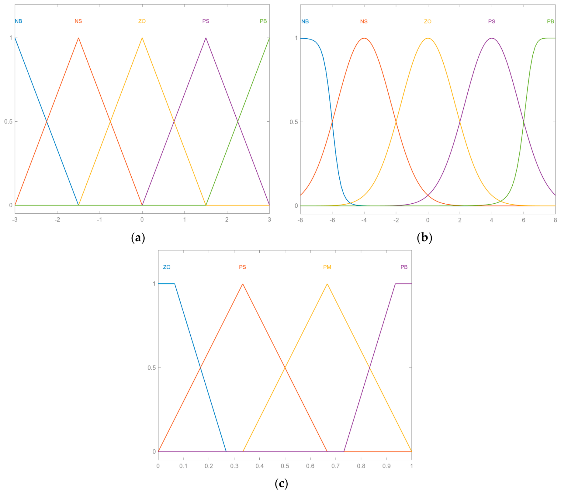
Based on the fuzzy control variables, two input variables are defined for the proposed fuzzy controller; namely the lateral position error and the heading angle error, which represent the deviations of the vehicle’s lateral position and heading angle from their corresponding reference values, respectively. Considering the vehicle dynamic characteristics during trajectory tracking, the universes of discourse for the lateral position error and the heading angle error are set to ([−3, 3]) and ([−8, 8]), respectively. Both input variables are fuzzified into five linguistic subsets: Negative Big (NB), Negative Small (NS), Zero (ZO), Positive Small (PS), and Positive Big (PB).
Since the front and rear steering angles are coordinated within the integrated control framework, identical weighting coefficients are assigned to the steering angle increments of the front and rear wheels to simplify the controller design while maintaining steering smoothness. Consequently, they are adaptively adjusted by the output variable
. As shown in Equation (23),
,
,
,
, the four output weighting ratios of the controller, denoted by
,
,
and
are defined within the range of ([0, 1]). These weighting ratios are fuzzified into four linguistic subsets: Zero (ZO), Positive Small (PS), Positive Medium (PM), and Positive Big (PB).
Based on the characteristics of the membership functions, the membership functions of the input and output variables are designed as shown in
Figure 3.
3.2.2. Definition of Fuzzy Rules
The fuzzy rule base is constructed to characterize the relationship between the input and output variables. These rules are established based on the vehicle trajectory tracking characteristics, the variation trends of the MPC weighting matrices, and extensive simulation studies. The resulting fuzzy rule bases are presented in
Table 1,
Table 2,
Table 3 and
Table 4.
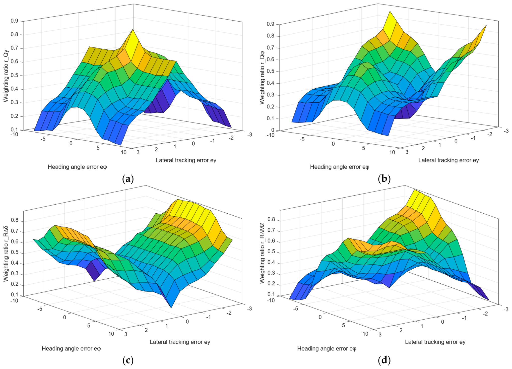
The response surfaces shown in
Figure 4 provide an intuitive representation of the mapping relationship between the input and output variables defined by the fuzzy rule base. According to the proposed fuzzy rules, when the lateral tracking error becomes larger, the weighting coefficient associated with the steering angle increment is increased. Since this weighting coefficient serves as a penalty term in the MPC cost function, larger steering increments are penalized more heavily. Consequently, abrupt steering actions are suppressed, leading to smoother steering behavior while maintaining trajectory tracking stability.
3.3. Torque Allocation Controller
Before investigating the lower-layer torque allocation strategy, the total driving force required by the vehicle must first be determined. The total driving force control belongs to a low-frequency control problem. Considering that the PID controller can satisfy the control requirements with relatively low computational complexity, a PID-based control method is adopted to calculate the required total driving force [
29], as expressed in Equation (24).
where
is the error between the actual vehicle speed and the reference speed, and
is the total driving force of the vehicle.
To ensure vehicle stability during driving, the torque allocation strategy should not only generate appropriate wheel torques but also satisfy various physical and operational constraints. When the wheel slip ratio becomes excessive or the vehicle operates at high speed, further increasing the driving torque may lead to vehicle instability. Therefore, the target driving torque obtained using conventional rule-based methods may no longer be applicable under such conditions. To address this issue, an optimal torque allocation strategy based on incorporating equality constraints into the objective function is proposed. The proposed method enables the optimal distribution of wheel torques while ensuring that all prescribed constraints are satisfied.
To perform the optimal torque allocation, the objective function must first be established to accurately reflect the control performance. Considering both vehicle driving stability and tire load utilization, the tire load ratio is selected as the optimization index. An optimization model is then formulated by minimizing the sum of the squared tire load ratios. The tire load ratio of each wheel can be expressed as follows:
In the simulation environment, the individual lateral tire forces are directly obtained from the CarSim high-fidelity vehicle model and are used as inputs to the torque allocation controller. In practical vehicle applications, however, these tire forces are generally unavailable for direct measurement. Instead, they can be estimated online using a vehicle state observer or a tire force estimator based on commonly available onboard measurements, such as steering angle, wheel speed, yaw rate, lateral acceleration, and longitudinal acceleration. Therefore, the proposed torque allocation strategy does not require direct tire force measurement and can be readily combined with existing tire force estimation techniques.
Accordingly, the longitudinal tire force
is selected as the optimization variable in the quadratic programming (QP) formulation. By neglecting the constant terms in the objective function, the tire load ratio objective function can be simplified to Equation (26). Considering the actual driving conditions and computational efficiency, the cost function is defined as follows:
The constraints are given as follows:
where
denote the torque of each wheel,
denotes the effective rolling radius of the tire, and
denote the front and rear track widths.
According to the constraints, the system has two input variables and four output variables, indicating that it is a redundant system. Therefore, methods such as quadratic programming and the Karush–Kuhn–Tucker (KKT) conditions can be used for solution. Considering control computational efficiency, the method of substituting equality constraints into the objective function to derive the optimal solution can significantly improve the solution speed. Since the front and rear track widths of the vehicle studied in this paper are approximately equal,
is defined accordingly. Thus, Equation (27) can be rewritten as follows:
Substituting Equation (28) into Equation (26) yields:
Taking the partial derivatives of Equation (29) with respect to
and
yields:
By setting the partial derivatives equal to zero, the minimum value can be obtained as follows:
Substituting Equation (31) into Equation (28) yields and .
The in-wheel motor is modeled as a simplified second-order system, which can be expressed as follows:
where
denotes the actual motor torque,
denotes the commanded motor torque, and
is the motor dynamic parameter governing the transient torque response. In this study,
is set to 0.02 s, representing the fast torque response of the in-wheel motor. This value was selected based on the typical actuator response characteristics adopted in distributed-drive electric vehicle simulations and was verified to provide stable torque tracking in the CarSim–Simulink co-simulation.
4. Simulation Validation
To verify the effectiveness of the proposed integrated control strategy and evaluate its overall performance in terms of trajectory tracking accuracy, response speed, and vehicle stability for an autonomous four-wheel steering (4WS) vehicle, a co-simulation platform based on CarSim and Simulink was established for analysis. The main vehicle parameters are listed in
Table 5.
Simulation studies were conducted under different vehicle speeds and road adhesion coefficients. Three control strategies were compared: the MPC-based front-wheel steering controller (MPC-FWS), the conventional MPC-based four-wheel steering controller (MPC-4WS), and the proposed improved MPC-based four-wheel steering controller (Improved MPC-4WS), which integrates a fuzzy adaptive weighting strategy with adaptive prediction and control horizon adjustment (APCHA). The performance of these controllers was comprehensively evaluated using multiple performance indices to clearly demonstrate the differences and advantages of the proposed control strategy. To further evaluate the respective contributions of the DYC module and the proposed torque allocation strategy, an additional ablation study was conducted. The weight coefficients of the classical predictive control controller are set as , , , .
- (1)
MPC-FWS: conventional MPC with fixed weighting matrices and fixed horizons using front-wheel steering;
- (2)
MPC-4WS: conventional MPC with fixed weighting matrices and fixed horizons using front- and rear-wheel steering;
- (3)
Improved MPC-4WS: the proposed controller incorporating fuzzy adaptive weighting, online adjustment of the prediction and control horizons through APCHA, and coordinated direct yaw moment control.
4.1. Medium-Speed, Low-Adhesion Road Condition
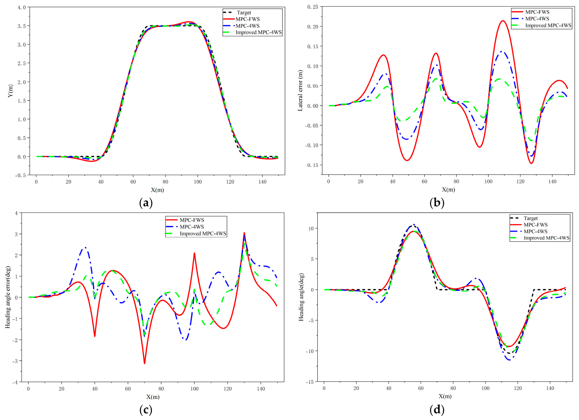
As shown in
Figure 5a, under a vehicle speed of 60 km/h and a road adhesion coefficient of
, all three control strategies are capable of tracking the reference trajectory. However,
Figure 5b,c indicate significant differences in tracking performance. The maximum lateral tracking errors of the conventional MPC-based front-wheel steering controller (MPC-FWS) and the conventional MPC-based four-wheel steering controller (MPC-4WS) are 0.2141 m and 0.1369 m, respectively, while their maximum heading angle errors reach 3.13° and 2.92°, respectively. In comparison, the proposed Improved MPC-4WS controller achieves a maximum lateral tracking error of only 0.089 m and a maximum heading angle error of 2.557°, respectively. As shown in
Table 6, compared with MPC-4WS, the proposed controller reduces the maximum lateral tracking error, RMSE, and MAE by 34.9%, 44.3%, and 45.2%, respectively. These results indicate that the improvement is maintained over the complete maneuver rather than being limited to an isolated peak value.
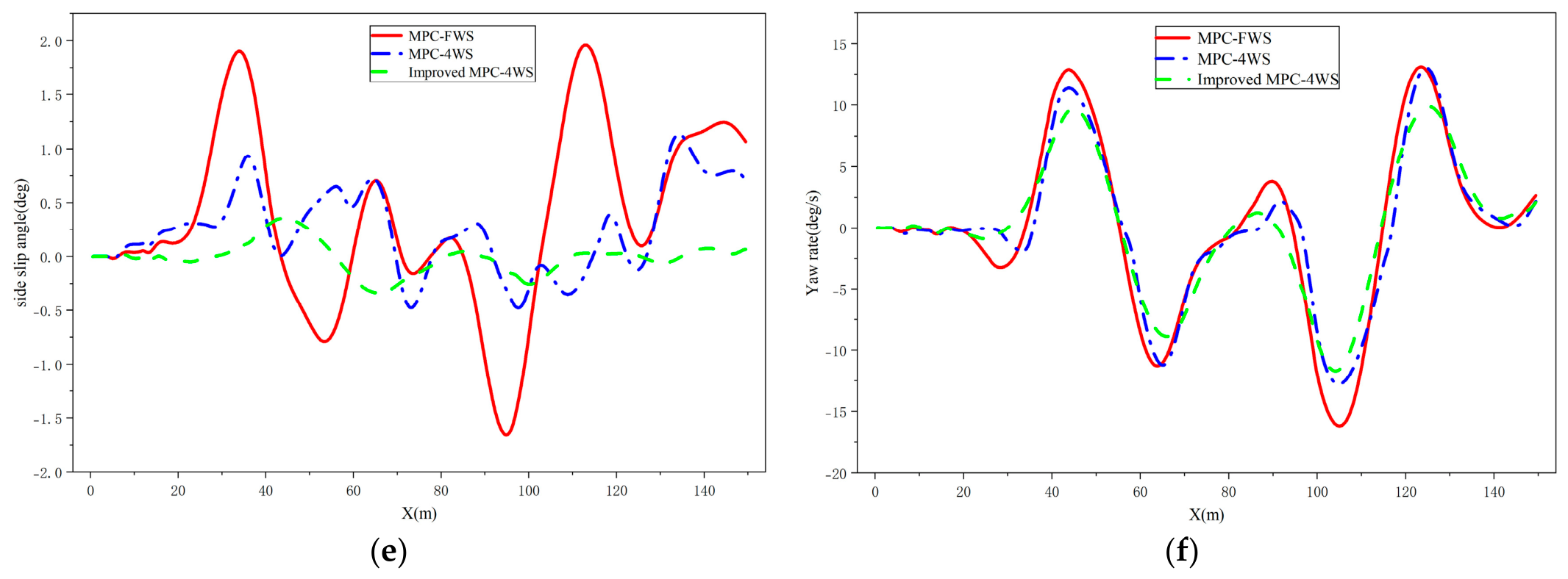
Figure 5d compares the heading angle responses of the three controllers. It can be observed that the Improved MPC-4WS controller tracks the reference heading angle more smoothly and accurately, indicating superior vehicle attitude stability under this operating condition. As shown in
Figure 5e, both the MPC-FWS and MPC-4WS controllers exhibit relatively large fluctuations in the vehicle sideslip angle. The maximum sideslip angle of the conventional MPC-4WS controller reaches 1.12°, whereas that of the proposed Improved MPC-4WS controller is reduced to only 0.40°. These results demonstrate that the proposed controller not only significantly improves trajectory tracking accuracy but also effectively suppresses sideslip angle fluctuations, thereby enhancing the lateral stability of the vehicle. Therefore, the simulation results verify that the proposed Improved MPC-4WS controller provides superior trajectory tracking performance and vehicle stability under medium-speed, low-adhesion road conditions.
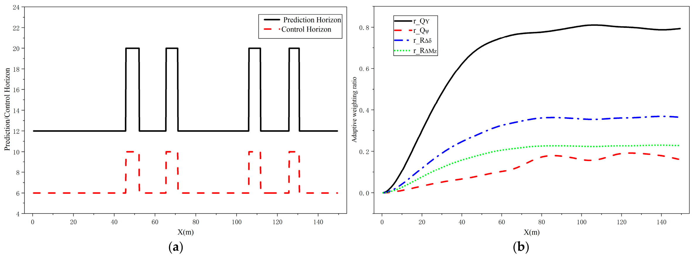
To further demonstrate the operation of the proposed adaptive MPC strategy, the online evolution of the prediction horizon, control horizon, and adaptive weighting ratios under the representative 60 km/h low-adhesion condition is presented in
Figure 6. As shown in
Figure 6a, the prediction horizon and control horizon are adjusted online according to the integrated tracking error, error variation rate, and control input variation rate. During sections with relatively large tracking errors, the prediction horizon increases from 12 to 20, while the control horizon simultaneously increases from 6 to 10. This enables the controller to obtain a longer prediction window and greater control flexibility. When the tracking condition becomes milder, both horizons return to their nominal values, thereby reducing the computational burden.
Figure 6b shows the online evolution of the adaptive weighting ratios. The output weighting ratios
and
are continuously adjusted according to the current tracking errors, thereby modifying the emphasis placed on lateral displacement and heading angle tracking. Meanwhile, the input weighting ratios
and
are also updated online to regulate the penalty imposed on the control increments. Consequently, the proposed fuzzy adaptive weighting mechanism dynamically balances tracking accuracy and control smoothness throughout the maneuver.
4.2. High-Speed, Medium-Adhesion Road Condition
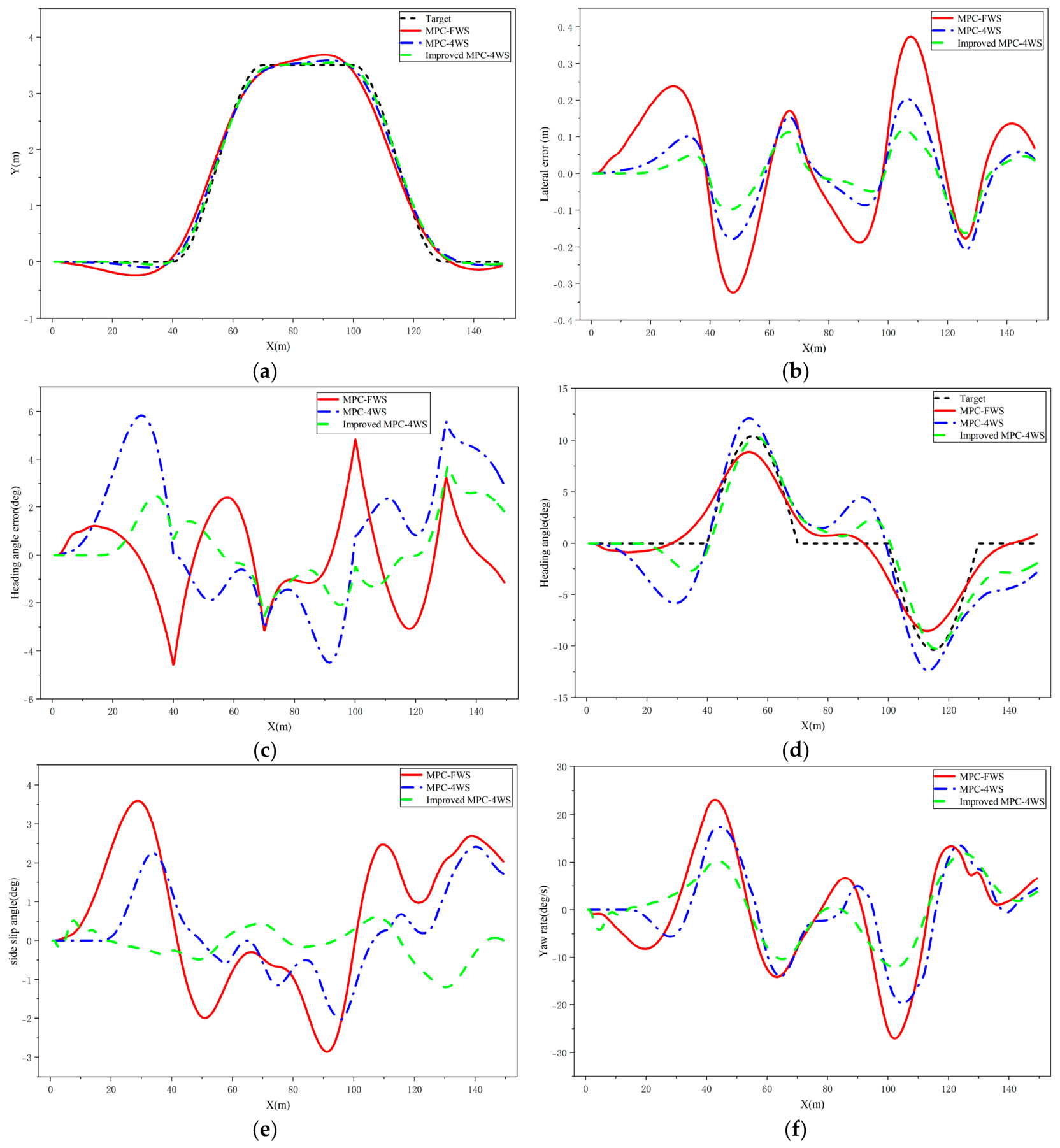
The longitudinal vehicle speed was set to 90 km/h, and the road adhesion coefficient was set to 0.6. The corresponding simulation results are presented in
Figure 7.
As shown in
Figure 7a,b, all three control strategies exhibit certain fluctuations in the lateral tracking error under high-speed driving conditions. The maximum lateral tracking errors of the MPC-based front-wheel steering controller (MPC-FWS) and the conventional MPC-based four-wheel steering controller (MPC-4WS) are 0.3742 m and 0.2071 m, respectively, whereas the proposed Improved MPC-4WS controller reduces the maximum lateral tracking error to 0.1630 m. Compared with MPC-4WS, the proposed controller reduces the maximum absolute lateral tracking error, RMSE, and MAE by 21.3%, 37.2%, and 40.5%, respectively. The reductions in RMSE and MAE demonstrate that the proposed controller improves the overall tracking performance throughout the maneuver rather than merely reducing an isolated peak error.
Figure 7c shows that the Improved MPC-4WS controller achieves the smallest heading angle error, which remains within the acceptable range throughout the simulation. As shown in
Table 7, the maximum absolute heading angle errors of MPC-FWS, MPC-4WS, and Improved MPC-4WS are 4.8305°, 5.8284°, and 3.7547°, respectively. The corresponding RMSE values are 1.8007°, 2.8856°, and 1.4459°, respectively. Compared with MPC-4WS, the proposed controller reduces the maximum absolute heading angle error, RMSE, and MAE by 35.6%, 49.9%, and 52.2%, respectively. Although the conventional MPC-4WS controller exhibits larger heading angle errors than MPC-FWS under this high-speed condition, the proposed controller achieves the lowest values for all three metrics, demonstrating improved coordination of the front- and rear-wheel steering actions. As illustrated in
Figure 7d, the proposed controller accurately tracks the reference heading angle, demonstrating excellent heading control performance.
Figure 7e,f further compare the vehicle sideslip angle and yaw rate responses. The MPC-FWS and conventional MPC-4WS controllers exhibit relatively large fluctuations in both variables, indicating an increased risk of vehicle instability under high-speed driving conditions. In contrast, the proposed Improved MPC-4WS controller maintains both the sideslip angle and yaw rate within a much narrower range, resulting in enhanced vehicle stability.
Under the tested high-speed, medium-adhesion condition, the proposed Improved MPC-4WS controller achieves lower tracking errors and more stable vehicle responses than the benchmark controllers.
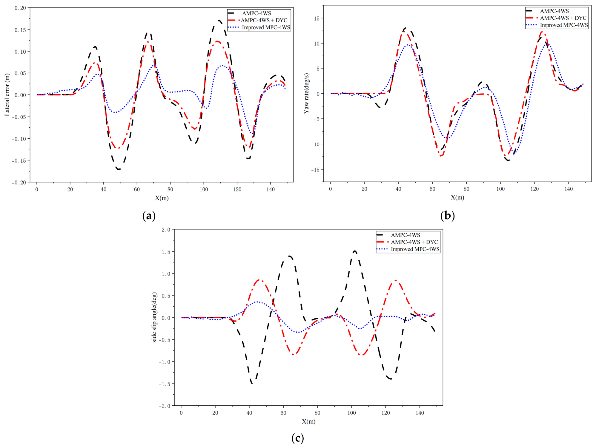
4.3. Ablation Study of the Integrated Control Framework
To further evaluate the individual contributions of the upper-layer adaptive MPC controller and the lower-layer DYC with torque allocation strategy, three control configurations are compared under the double lane-change maneuver at a vehicle speed of 60 km/h and a road adhesion coefficient of 0.5:
- (1)
AMPC-4WS: The adaptive MPC controller is employed to generate the front- and rear-wheel steering commands without the DYC module;
- (2)
AMPC-4WS with DYC: The adaptive MPC controller is integrated with the DYC module, where the additional yaw moment is distributed using the conventional rule-based torque allocation strategy;
- (3)
Improved MPC-4WS: The complete proposed integrated control framework, consisting of the adaptive MPC controller, the DYC module, and the proposed optimized torque allocation strategy.
The comparison aims to separately investigate the influence of DYC and the proposed torque allocation strategy on vehicle trajectory tracking performance and lateral stability.
As shown in
Table 8, introducing the DYC module significantly improves both trajectory tracking accuracy and vehicle lateral stability compared with the AMPC-4WS controller. Specifically, the maximum lateral tracking error is reduced from 0.17071 m to 0.12377 m, corresponding to a reduction of approximately 27.5%. Meanwhile, the lateral tracking RMSE decreases from 0.08657 m to 0.06416 m, and the MAE decreases from 0.06701 m to 0.04892 m. In addition, the maximum sideslip angle is reduced from 1.51226° to 0.85826°, while the sideslip angle RMSE decreases from 0.70869° to 0.43511°, indicating that the DYC module effectively enhances vehicle lateral stability.
By further replacing the conventional rule-based torque distribution with the proposed optimized torque allocation strategy, the Improved MPC-4WS controller achieves the best overall performance. Compared with AMPC-4WS + DYC, the maximum lateral tracking error is further reduced to 0.08907 m, representing an additional reduction of approximately 28.0%. Moreover, the lateral tracking RMSE and MAE decrease to 0.03318 m and 0.02500 m, respectively. The maximum sideslip angle is further reduced to 0.35506°, while the sideslip angle RMSE decreases to 0.15139°, demonstrating that the proposed torque allocation strategy further improves both trajectory tracking accuracy and vehicle lateral stability.
The dynamic responses shown in
Figure 8 are consistent with the quantitative results. As illustrated in
Figure 8a, the Improved MPC-4WS controller exhibits the smallest lateral tracking error throughout the double lane-change maneuver. Compared with the other two controllers, the tracking error is effectively suppressed, especially during the lane-transition stages where large lateral accelerations occur.
Figure 8b shows that incorporating the DYC module significantly improves the yaw rate response, while the proposed optimized torque allocation further smooths the yaw rate variation and suppresses excessive yaw motion during rapid steering maneuvers.
Furthermore,
Figure 8c demonstrates that the sideslip angle is greatly reduced after introducing the DYC module. The proposed optimized torque allocation further suppresses the peak sideslip angle and maintains the sideslip response closer to zero throughout the maneuver, indicating improved lateral stability and better utilization of the available tire forces.
Therefore, the comparison confirms that the performance improvement of the proposed integrated controller is jointly achieved by the upper-layer adaptive MPC and the lower-layer DYC with optimized torque allocation. Specifically, DYC is mainly responsible for improving lateral stability, while the proposed torque allocation strategy further enhances trajectory tracking performance by more effectively utilizing the available tire forces.
5. Discussion
The integrated trajectory tracking control strategy for distributed four-wheel steering (4WS) vehicles based on online parameter reconfiguration model predictive control (Online Parameter Reconfiguration MPC) proposed in this paper achieves coordinated lateral–longitudinal vehicle motion control through the synergistic integration of fuzzy adaptive weight adjustment, adaptive prediction and control horizon adjustment, and direct yaw moment control (DYC). Simulation results demonstrate that, compared with the conventional MPC control strategy, the proposed method effectively reduces the lateral tracking error and heading angle error while significantly improving the trajectory tracking accuracy and vehicle stability under high-speed cornering conditions.
From the perspective of the control mechanism, conventional MPC generally employs fixed prediction and control horizons together with fixed weighting matrices. Consequently, when the vehicle operating conditions change, it is difficult for the controller to achieve high tracking accuracy. The proposed adaptive prediction and control horizon adjustment strategy dynamically adjusts the prediction horizon and control horizon according to the comprehensive tracking error, the error variation rate, and the control input variation rate. Specifically, when the tracking error becomes large, the prediction horizon is extended to enhance the prediction capability and improve trajectory tracking performance. Conversely, as the vehicle gradually approaches the desired trajectory, the prediction horizon is appropriately shortened to reduce the online computational burden of the controller. Therefore, the proposed strategy provides an online mechanism for balancing tracking accuracy and control smoothness, according to the current tracking and control states.
Furthermore, the proposed fuzzy adaptive weighting strategy enables the MPC weighting matrices to be adjusted online according to the current tracking errors. Unlike the conventional fixed-weight design, the weighting matrices of the MPC cost function are adjusted online according to the lateral tracking error and heading angle error. Consequently, the controller can automatically shift its control emphasis in response to changes in the vehicle operating state. Specifically, when the tracking error is relatively large, the weighting on the state error is increased to improve trajectory tracking performance. As the vehicle gradually converges to the reference trajectory, the weighting on the control input is appropriately increased to suppress steering oscillations and improve driving smoothness. Therefore, the proposed strategy not only maintains high tracking accuracy but also enhances the continuity of the control inputs.
At the execution layer, a direct yaw moment control (DYC) strategy is further introduced, and the driving torques are optimally allocated according to the principle of minimizing the tire load ratio. By fully exploiting the independent driving capability of distributed-drive electric vehicles, the proposed torque allocation method achieves a reasonable distribution of the four-wheel driving torques while simultaneously satisfying the required longitudinal driving force and the additional yaw moment. This strategy effectively improves vehicle handling stability and enhances tire force utilization under various driving conditions.
In existing studies, most current approaches focus on a single aspect, such as MPC weight optimization, prediction horizon optimization, or four-wheel steering control. In contrast, the proposed control framework integrates online horizon adjustment, fuzzy adaptive weighting, four-wheel steering control, direct yaw moment control (DYC), and tire load ratio-based optimal torque allocation into a unified control architecture. This integrated design enables the coordinated optimization of trajectory tracking performance and vehicle stability. Consequently, the proposed integrated strategy achieves better trajectory tracking performance than the benchmark controllers under the tested conditions. The superior simulation results obtained in comparison with the conventional MPC strategy further demonstrate the effectiveness and advantages of the proposed integrated control framework.
It should be noted that the proposed MPC controller is designed based on a simplified linear prediction model, whereas the CarSim vehicle model employs nonlinear tire characteristics. The satisfactory tracking performance obtained in the co-simulation demonstrates that the proposed controller maintains satisfactory trajectory tracking performance under the tested operating conditions. Nevertheless, under extreme limit-handling conditions involving severe tire saturation, the prediction accuracy may deteriorate, and incorporating nonlinear tire models or LPV/nonlinear MPC constitutes an important direction for future work.
Although all online-adjusted weighting coefficients and prediction/control horizons are restricted within predefined bounded intervals, these bounds alone do not constitute a rigorous proof of closed-loop stability. The complete control framework involves fuzzy parameter scheduling, time-varying MPC parameters, nonlinear vehicle dynamics, and hierarchical torque allocation. Therefore, the conventional stability conditions derived for fixed-parameter MPC cannot be directly applied to the entire closed-loop system. In the present study, the effectiveness of the controller is evaluated through co-simulation, while a formal analysis of recursive feasibility and closed-loop stability remains to be established.
The in-wheel motors are represented by simplified second-order models with fixed parameters in the present study. However, in practical electric-drive systems, electrical parameters may vary with motor temperature and operating conditions, while the load torque and equivalent moment of inertia may also change during vehicle operation. These variations may introduce a mismatch between the nominal motor model and the actual drive system, resulting in degraded torque-tracking accuracy, slower transient response, and increased torque error.
Because the wheel torques are used to realize the longitudinal force and additional yaw moment commands generated by the upper-level controller, motor parameter uncertainties may also influence the overall vehicle control performance. In particular, wheel torque tracking errors may cause the realized yaw moment to deviate from its desired value, thereby affecting the yaw response, sideslip angle suppression, and trajectory tracking accuracy [
30,
31].
It should be noted that several limitations still exist in the present study. First, the proposed controller has only been validated through CarSim–Simulink co-simulation, while the influences of practical factors, such as sensor noise, actuator delay, model parameter perturbations, and complex road environments, have not yet been fully considered. In addition, the fuzzy rule base and several controller parameters are still determined empirically and therefore require recalibration for different vehicle platforms and operating conditions. Although the proposed controller showed improved tracking and stability performance under the tested operating conditions, the current study is limited to two fixed speed–adhesion combinations.
Future work will focus on further improving the robustness, adaptability, and engineering applicability of the proposed control framework. First, rigorous theoretical analyses, including recursive feasibility, terminal cost and terminal constraint design, and Lyapunov-based stability analysis, will be developed to provide formal stability guarantees for the online parameter-reconfigured MPC framework. Second, advanced optimization and learning techniques, such as Genetic Algorithms (GA), Particle Swarm Optimization (PSO), reinforcement learning, and data-driven approaches, will be investigated to optimize the fuzzy membership functions, fuzzy rule base, and controller parameters, thereby enhancing the controller adaptability under varying driving conditions. Furthermore, online identification of motor electrical and mechanical parameters, tire–road friction coefficient estimation, and explicit consideration of tire nonlinearities, actuator delays, model uncertainties, measurement noise, and external disturbances will be incorporated to improve the robustness and accuracy of both upper-level vehicle motion control and lower-level torque allocation. Finally, the proposed controller will be implemented on an embedded real-time platform and validated through hardware-in-the-loop and real vehicle experiments, where computational efficiency, solver performance, control smoothness, and additional vehicle dynamics performance indices will be comprehensively evaluated under more diverse operating conditions, including varying road adhesion, complex path geometries, and uncertain driving environments.
6. Conclusions
To improve the trajectory tracking accuracy of autonomous four-wheel steering (4WS) vehicles, this study proposes an integrated trajectory tracking control strategy that combines adaptive prediction and control horizon adjustment, fuzzy adaptive weighting control, and direct yaw moment control (DYC). In the upper-layer controller, the APCHA strategy is employed to realize the online adjustment of the prediction horizon and control horizon, while a fuzzy adaptive weighting strategy is introduced to optimize the weighting matrices of the MPC cost function. In the lower-layer controller, a PID controller is adopted to calculate the total driving force, and an optimal torque allocation strategy is formulated by minimizing the sum of the squared tire load ratios, thereby achieving the optimal distribution of the four-wheel driving torques.
The effectiveness of the proposed control strategy is validated through CarSim–Simulink co-simulation under medium-speed/low-adhesion and high-speed/medium-adhesion driving conditions. Compared with the conventional MPC-based four-wheel steering controller, the proposed Improved MPC-4WS controller demonstrates superior trajectory tracking performance and vehicle stability. In particular, under the 60 km/h, condition, the maximum lateral tracking error is reduced by 34.9% compared with MPC-4WS, while the heading angle error and vehicle dynamic responses are further improved. The additional contribution analysis further confirms that the DYC module effectively enhances vehicle lateral stability, and the proposed optimized torque allocation strategy provides further reductions in lateral tracking error and sideslip angle compared with the conventional DYC-based controller. These results demonstrate that the coordinated design of adaptive MPC, DYC, and optimized torque allocation enables the proposed integrated control framework to achieve superior trajectory tracking accuracy and vehicle stability.