Article

Online Multi-Parameter Identification of PMSM Drives Using a Fuzzy PI-Tuned MRAS Observer

1
School of Mechanical and Automotive Engineering, Shanghai University of Engineering Science, 333 Longteng Road, Shanghai 201620, China
2
Jiangsu Firstwise New Energy Technology Co., Ltd., Building A4, No. 1088, Fengxing Road, Huaqiao Town, Kunshan 215332, China
*
Author to whom correspondence should be addressed.
World Electr. Veh. J. 2026, 17(8), 417; https://doi.org/10.3390/wevj17080417
Submission received: 2 July 2026 / Revised: 31 July 2026 / Accepted: 7 August 2026 / Published: 9 August 2026
(This article belongs to the Section Vehicle Control and Management)

Abstract

Permanent magnet synchronous motors (PMSMs) are widely used in AC drive systems, and their control performance depends strongly on accurate motor parameters. Conventional proportional-integral model reference adaptive system (PI-MRAS) observers use fixed adaptation gains, resulting in a trade-off between rapid convergence and low steady-state fluctuation. To address this limitation, this paper proposes a fuzzy proportional integral (Fuzzy-PI)-tuned MRAS observer for the simultaneous online identification of stator resistance (Rs) and stator inductance (Ls). The parameter-error dynamics are formulated from the PMSM model, and the adaptation laws are derived using Popov hyperstability theory. A fuzzy tuner uses the absolute identification error and its rate of change to schedule the proportional and integral gains online, thereby accelerating transient error convergence when the identification error is large and reducing estimation oscillations during steady-state operation. The method is evaluated through simulation and laboratory experiments involving rated operation, speed variation, parameter perturbation, and load disturbance. Under the investigated conditions, the identification errors of Rs and Ls are 3.8% and 0.18%, respectively. Compared with the conventional PI-MRAS, the reported Rs identification error decreases from 8.1% to 3.8% and the Ls identification error decreases from 0.91% to 0.18%. The results demonstrate an improved identification accuracy and disturbance recovery within the tested operating range. The implementation on an Infineon TC233 platform also demonstrates real-time feasibility, while broader validation under temperature variation, magnetic saturation, inverter nonlinearity, and measurement noise remains necessary.

1. Introduction

PMSMs are widely used in the field of AC drives due to their advantages such as high efficiency, high controllability, and high power density. Some control algorithms for PMSMs, such as vector control and direct torque control, require knowledge of the motor parameters. However, these parameters are not constant during motor operation and are influenced by factors such as temperature, frequency, and magnetic saturation. Therefore, accurate real-time identification of motor parameters and their incorporation into the control algorithm are essential for achieving high-performance motor control.
Currently, the commonly used online parameter identification methods [1] for PMSMs include recursive least squares (RLS), extended Kalman filter (EKF), MRAS, and intelligent algorithms. When RLS [2,3,4,5] is used for parameter identification, unbiased estimation can only be guaranteed when the equation error satisfies the white-noise assumption. However, under actual operating conditions, there are model errors, observation errors, and external disturbances, making RLS susceptible to measurement noise interference. EKF [6,7,8,9,10,11,12,13] relies on local linearization of nonlinear models, and the approximation error may degrade parameter estimation accuracy, and this linearization error can lead to increased inaccuracy in the identification results. Furthermore, EKF involves a large computational burden, and parameters such as the noise covariance matrix are difficult to obtain accurately, which complicates the implementation of the algorithm. The introduction of intelligent algorithms [14,15,16,17,18] (such as neural networks, fuzzy logic, and reinforcement learning) is primarily aimed at addressing the challenges of insufficient adaptability and decreased robustness that traditional control methods (e.g., PID) face when dealing with nonlinearity, time-varying parameters, and complex operating conditions. In summary, the advantages of intelligent algorithms lie in their “flexibility” and “self-adaptability”, but they may suffer from increased computational complexity and reduced interpretability.
An MRAS takes the motor as a reference model, selects an equation containing the parameters to be identified as an adjustable model, and designs an adaptive law to make the parameters in the adjustable model gradually converge to the actual values. Conventional MRAS approaches commonly employ PI-based adaptive laws for parameter estimation. However, the fixed-gain adaptive law may lead to a trade-off between convergence speed and steady-state accuracy. When parameters change, the estimation accuracy of the traditional MRAS algorithm also declines, failing to meet the requirements for real-time accuracy in parameter identification.
To further improve the estimation accuracy and robustness of MRAS-based sensorless control, several enhanced observer structures have been reported in recent years. Liu [19] proposed a switched PI control-based MRAS observer using a fuzzy-logic controller for PMSM drives, in which different PI adaptive mechanisms were selected according to the current error to improve the robustness of speed estimation and Rs identification. Bıçak and Gelen [20] developed a modified super-twisting algorithm-based MRAS observer for interior PMSMs used in electric vehicles, where the sigmoid switching function and adaptive sliding-mode coefficient were introduced to enhance the performance of sensorless field-oriented control (FOC) under flux-weakening and maximum-torque-per-ampere operation. Khanh and Anh [21] presented an advanced fuzzy MRAS algorithm for sensorless PMSM speed control, aiming to reduce the chattering phenomenon in speed estimation and improve the dynamic response of the closed-loop system. Sun [22] combined an improved back-EMF observer with an extended state observer to construct an adaptive robust sensorless control scheme, which enhanced the anti-disturbance capability of PMSM drives.
In addition to MRAS-based methods, model predictive control and intelligent control strategies have also been widely investigated for PMSM drives. Niu [23] proposed a model predictive current control method with adaptive-adjusting timescales, which improved the transient prediction accuracy while reducing the computational burden in steady-state operation. Brosch [24] estimated torque and inductance parameters for finite-control-set model predictive control of highly utilized PMSMs, thereby improving the reliability of predictive control under parameter variations. Sun [25] introduced an adaptive fuzzy control algorithm to improve PMSM efficiency and flux-linkage estimation accuracy. Wang [26] designed a PSO-based fuzzy sliding-mode controller for PMSM speed regulation, where particle swarm optimization was used to tune sliding-mode parameters and fuzzy control was applied to suppress chattering.
Although the above studies improved PMSM sensorless control, speed observation, predictive control, and fuzzy control performance from different perspectives, most of them mainly focused on rotor speed estimation or speed regulation. The simultaneous online identification of multiple key PMSM parameters, including Rs and Ls, still requires further improvement under wide-speed-range operation, load disturbance, and parameter perturbation. Therefore, this paper proposes a Fuzzy PI-MRAS-based online multi-parameter identification method to dynamically tune the PI adaptive law and improve the identification accuracy and robustness of PMSM drives.
The main contributions of this work are summarized as follows:
(1)
A two-parameter MRAS formulation is developed for simultaneous online estimation of Rs and Ls using measured dq-axis electrical variables.
(2)
Popov hyperstability theory is used to derive the PI-type adaptation law and to state the boundedness, sign, and excitation assumptions required for convergence.
(3)
A seven-level fuzzy tuner schedules the proportional and integral adaptation gains from the absolute identification error and its rate of change, balancing transient convergence and steady-state fluctuation without matrix inversion.
(4)
The method is implemented on an Infineon TC233 digital control platform and compared with conventional PI-MRAS methods in three laboratory operating cases. Implementation details, convergence curves, computational-complexity considerations, and limitations under non-ideal effects are provided.
Table 1 shows the comparison with recent MRAS methods.

2. PMSM Model and MRAS Algorithm

2.1. PMSM Model

For the surface-mounted PMSM considered in this study, Ld = Lq = Ls. After applying the Clarke transformation (abc to alpha–beta) and the Park transformation (alpha–beta to dq), the stator-voltage equations in the synchronously rotating dq reference frame can be written in state-space form as follows:
d d t i d d d t i q = R s L s ω e ω e R s L s i d i q + u d L s u q ω e ψ f L s
In Equation (1), ud and uq are the dq-axis stator voltages; id and iq are the dq-axis stator currents; Rs is the stator resistance; Ls is the stator inductance; ψ f is the permanent-magnet flux linkage; and ω e is the electrical angular speed. Equation (1) is obtained from the dq-axis voltage balance and describes the electrical current dynamics. It provides the physical plant model from which both the reference model and the adjustable model are constructed. The measured phase currents ia, ib, and ic are transformed to id and iq through the Clarke and Park transformations using the measured rotor electrical angle.
To separate the measured state variables from the unknown parameter combinations, Equation (1) is rearranged by defining the matrices and vectors below:
H = J ω ω J ; J = R s L s ; N = 1 L s ; M = ψ f L s ; i = i d i q ; v = u d u q ; z = 0 ω
Using the definitions above, the reference-model dynamics can be written compactly as follows:
i · = H i + N v + M z ;
Equation (2) is the measured-parameter form of the PMSM electrical dynamics. The matrix H contains the speed-dependent cross-coupling terms, while N and M multiply the applied voltage and speed inputs. This compact form makes the parameter-dependent coefficients explicit and is used as the reference model in the subsequent MRAS derivation.
Replacing the parameter-dependent coefficients in Equation (2) with their estimated values yields the adjustable model, as follows:
i · = H i + N v + M z ;
The adjustable model has the same measured inputs and state structure as the reference model, but it uses estimated coefficients derived from the online estimates of Rs and Ls. The difference between the two model outputs therefore reflects parameter mismatch as well as measurement and modeling errors.
Where
H = J ω ω J ; J = R s L s ; N = 1 L s ; M = ψ f L s ; i = i d i q ; v = v = u d u q ; z = z = 0 ω
The current-state estimation error is defined as follows:
e = i i
The error vector contains the d- and q-axes current-model mismatches. It is the feedback signal used by the adaptation mechanism; driving e toward zero makes the adjustable model reproduce the measured current dynamics.
Subtracting the adjustable model from the reference model results in the error dynamics as follows:
e · = H e + ( H H ) i + ( N N ) v + ( M M ) z
Equation (5) separates the stable nominal error dynamics, He, from the terms produced by parameter mismatch. This separation is essential because the mismatch terms form the nonlinear feedback input used in the Popov hyperstability analysis.

2.2. MRAS Observer Design

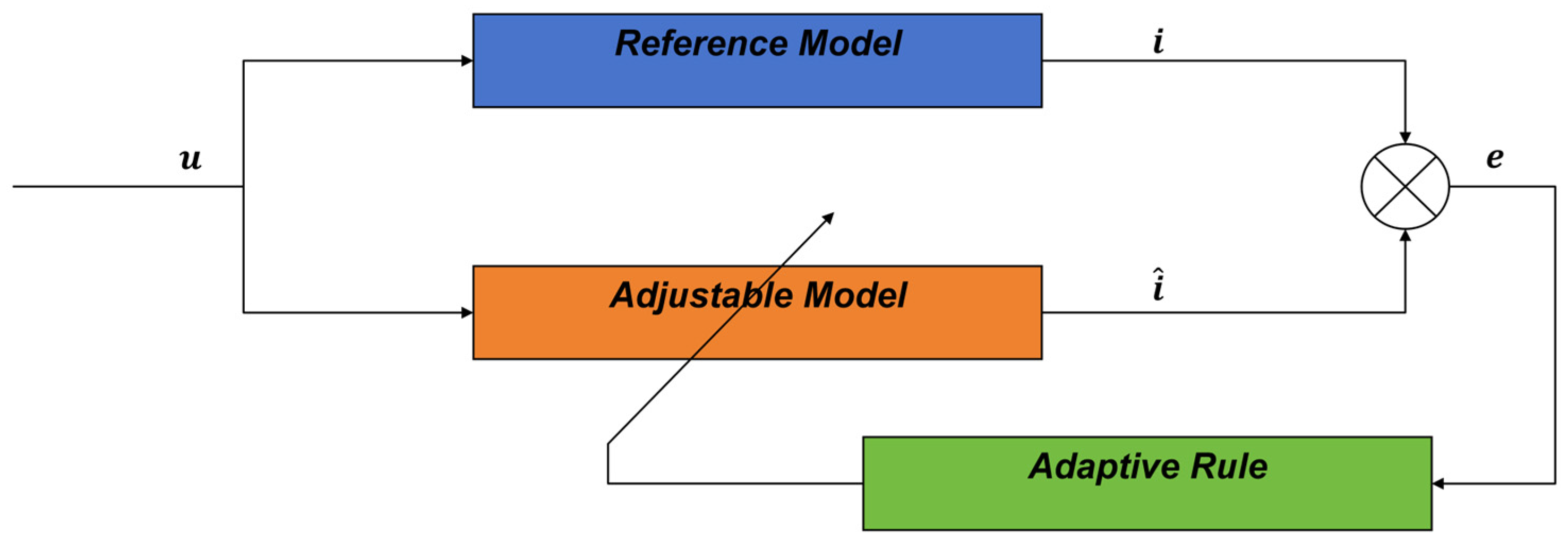
Two models operating simultaneously with the same physical output are defined as the adjustable model and the reference model. The adjustable model is represented by equations containing unknown parameters, while the reference model is represented by equations without unknowns. The difference between the outputs of the two models passes through an adaptation mechanism, and the parameters in the adjustable model are adjusted in real-time through an appropriate adaptive law. Ultimately, the outputs of the adjustable model and the reference model are made consistent. Consequently, the estimated parameters in the adjustable model converge to correct values, thus obtaining the parameters to be identified.
Figure 1 shows the input common to both models, i is the state vector of the reference model, and i is the state vector of the adjustable model. The difference after comparing i and i approaches zero.
The adaptation law may be designed using local parameter optimization, Lyapunov analysis, or Popov hyperstability theory. Local optimization provides a direct gradient-type rule but does not by itself establish closed-loop stability. Lyapunov design is rigorous but requires the selection of a suitable composite energy function for the coupled state and parameter errors. Popov hyperstability is adopted here because it provides a convenient input–output condition for combining a strictly positive-real linear error model with a nonlinear, time-varying adaptation block.
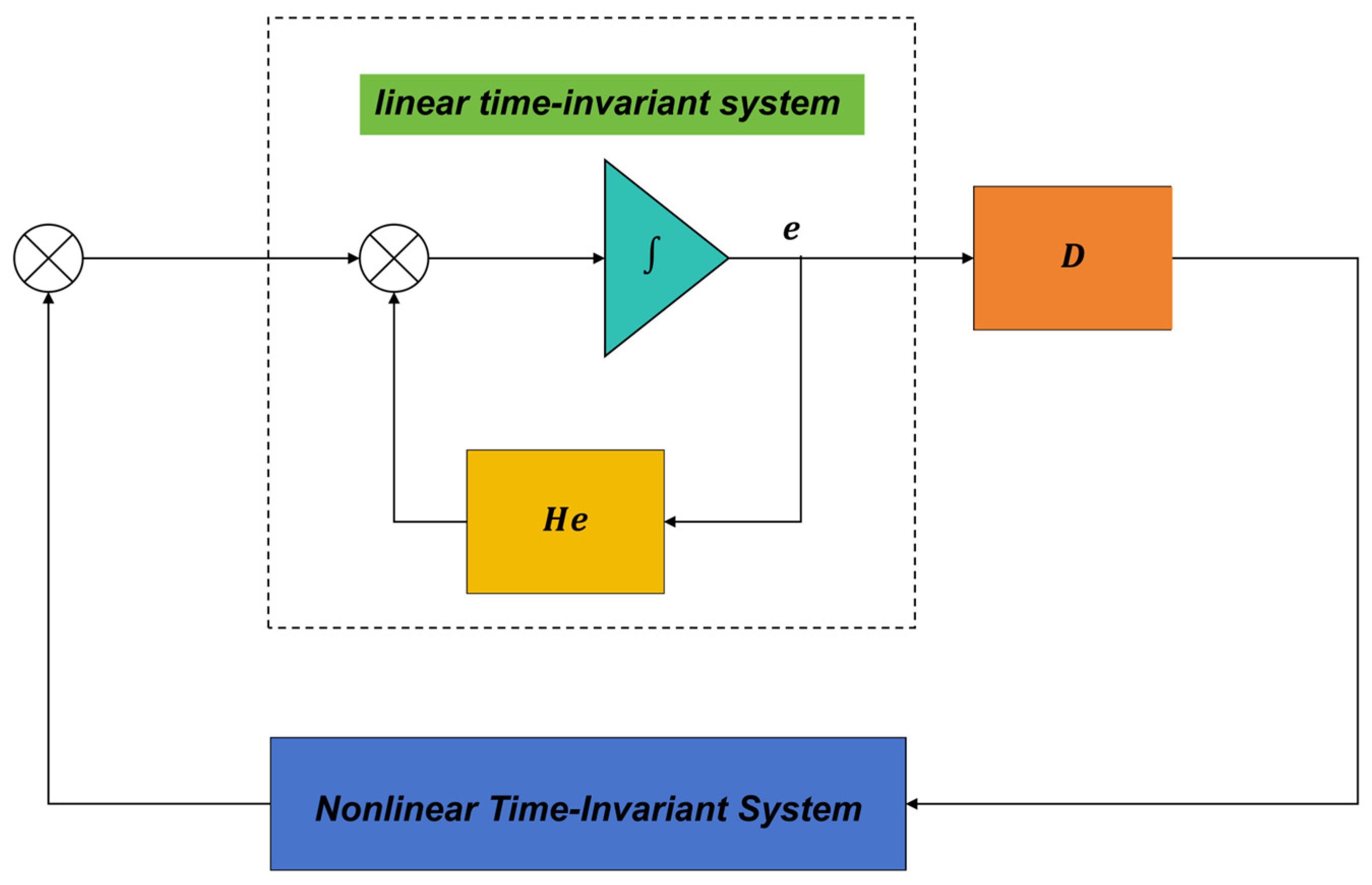
In the present MRAS, the current-error dynamics are interpreted as the linear forward block, while the parameter-mismatch and adaptation terms form the nonlinear feedback block shown in Figure 2. If the linear block is stable and strictly positive real and the nonlinear block satisfies the Popov integral inequality, the closed-loop signals remain bounded and the model error converges under the stated assumptions. Parameter convergence toward the physical values further requires sufficient excitation and identifiability of Rs and Ls. The derivation assumes the following: (i) an SPMSM with Ld = Lq; (ii) bounded and correctly transformed voltage, current, and speed signals; (iii) positive, slowly varying electrical parameters during one adaptation interval; (iv) positive adaptation gains; and (v) neglect of the inverter dead time, sensor bias, and magnetic saturation in the nominal model, as Figure 2 shows.
Let
W 1 = ( H H ) i + ( N N ) v + ( M M ) z
Equation (6) collects the differences between the true and estimated model coefficients and, therefore, represents the equivalent disturbance caused by the parameter mismatch.
W = W 1
Equation (7) defines the nonlinear feedback input. The minus sign is selected to match the negative-feedback convention used in the Popov representation.
e · = H e W
Equation (8) expresses the current-error system as a linear block driven by the nonlinear adaptation signal W. This form allows the MRAS to be analyzed using an input–output hyperstability condition.
The error vector is then mapped to the Popov output vector, V, as follows:
V = C e
Here C is a constant output-selection matrix chosen so that the transfer from W to V is strictly positive real. According to the Popov hyperstability theory, the nonlinear time-varying feedback block must satisfy the following integral inequality, as follows:
t > 0 , η ( 0 , t ) = 0 t V t W d t r 2
Equation (10) bounds the energy supplied by the nonlinear feedback block from below. Satisfaction of this inequality, together with the strictly positive-real linear block, establishes bounded closed-loop behavior.
Substituting V and W into the Popov inequality and grouping the individual parameter-mismatch terms yields the following:
η ( 0 , t ) = 0 t e T ( H H ) i d t 0 t e T ( N N ) v d t 0 t e T ( M M ) z d t r 2
Equation (11) decomposes the total Popov integral into contributions associated with the estimated coefficients. Each contribution can be made to satisfy a Popov inequality by selecting a positive PI-type adaptation law.
The three coefficient-related components of Equation (11) are written separately in Equations (12)–(14), as follows:
t 1 > 0 , η 1 ( 0 , t 1 ) = 0 t 1 e T ( H H ) i d t r 1 2
t 2 > 0 , η 2 ( 0 , t 2 ) = 0 t 2 e T ( N N ) v d t r 2 2
t 3 > 0 , η 3 ( 0 , t 3 ) = 0 t 3 e T ( M M ) z d t r 3 2
Equations (12)–(14) isolate the cross-product between the current-model error and each regressor. This separation enables independent construction of adaptation laws for the coefficient combinations that contain Rs and Ls.
The adaptation law is first derived from the coefficient term in Equation (12), as follows:
t 1 > 0 , η 1 ( 0 , t 1 ) = 0 t 1 e T ( H H ) i d t = 0 t 1 R s L s R s L s ( e 1 i d e 2 i q ) d t r 1 2
Equation (15) shows that the relevant parameter-coefficient error is multiplied by a measurable error-regressor signal. This signal becomes the input of the proportional and integral adaptation channels.
A PI-type coefficient update is selected to provide both rapid proportional correction and zero steady-state coefficient error, as follows:
R s L s R s L s = 0 t 1 R 1 ( τ ) d τ + R 2 ( τ )
In Equation (16), R 1 ( τ ) and R 2 ( τ ) denote the integral and proportional correction terms. Their signs and magnitudes are selected so that the corresponding Popov integral remains bounded below.
Substituting (16) into (15) results in the following:
t 1 > 0 , η 1 ( 0 , t 1 ) = 0 t 1 0 t 1 R 1 ( τ ) d τ ( e 1 i d e 2 i q ) d t 0 t 1 R 2 ( τ ) ( e 1 i d e 2 i q ) d t r 1 2
The resulting Popov integral is separated into the integral and proportional contributions, as follows:
η 11 ( 0 , t 11 ) = 0 t 11 0 t R 1 ( τ ) d τ ( e 1 i d e 2 i q ) d t r 11 2
η 12 ( 0 , t 12 ) = 0 t 12 R 2 ( τ ) ( e 1 i d e 2 i q ) d t r 12 2
The first contribution is handled using the standard quadratic integral identity, as follows:
0 t d f t d t k f t d t = k 2 f 2 ( t ) f 2 ( 0 ) 1 2 k f 2 0
Define the measurable adaptation signal and its integral as follows:
d f t d t = ( e 1 i d e 2 i q )
k f t = 0 t R 1 τ d τ
Differentiating the quadratic term and choosing a positive integral gain results in the following:
R 1 ( τ ) = K i 1 ( e 1 i d e 2 i q ) ( K i 1 > 0 )
With Ki1 > 0, the integral contribution satisfies the Popov lower bound. For the proportional contribution, the gain must also remain positive, as follows:
R 2 ( τ ) = K p 1 ( e 1 i d e 2 i q ) ( K p 1 > 0 )
Substituting the positive integral and proportional gain choices into Equation (17) satisfies the Popov inequality for this coefficient channel.
The resulting PI adaptation law is, therefore, as follows:
R s L s R s L s = K i 1 0 t ( e 1 i d e 2 i q ) d τ + K p 1 ( e 1 i d e 2 i q )
Equation (25) combines an accumulated correction and an instantaneous correction. The integral term removes persistent coefficient mismatch, while the proportional term improves the transient response. The fuzzy tuner, introduced in Section 2.3., schedules the positive gains without changing the sign conditions required by the Popov derivation.
Applying the same procedure to the remaining coefficient channel gives the complete online update equations for the parameter combinations associated with Rs and Ls, as follows:
R s L s = R s L s K i 1 0 t ( e 1 i d e 2 i q ) d τ K p 1 ( e 1 i d e 2 i q ) 1 L s = 1 L s + K i 2 0 t ( e 1 u d e 2 u q ) d τ + K p 2 ( e 1 u d e 2 u q )
Equation (26) is the complete two-parameter adaptation system used in the implementation. The estimated coefficient ratios are converted to Ls and Rs after each update. The gains Kp1, Ki1, Kp2, and Ki2 are constrained to positive ranges. No additional Luenberger observer gain is used; the adjustable-model correction is produced by the parameter adaptation itself.
The Rs and Ls are recovered from Equation (26). Their transient and steady-state behavior depends strongly on the adaptation gains: aggressive gains accelerate convergence but amplify ripple, whereas conservative gains reduce ripple but delay recovery. This motivates the fuzzy online gain-scheduling mechanism described next.

2.3. Fuzzy PI-MRAS Observer Design

The fuzzy tuner adjusts the proportional and integral gains of Equation (26) online. Its inputs are the normalized absolute identification error E = |e| and the normalized error-change rate EC = d|e|/dt. The outputs are the normalized gain commands for Kp and Ki. Figure 3 shows the signal flow from error calculation and fuzzification to rule inference, defuzzification, and the MRAS adaptation law.
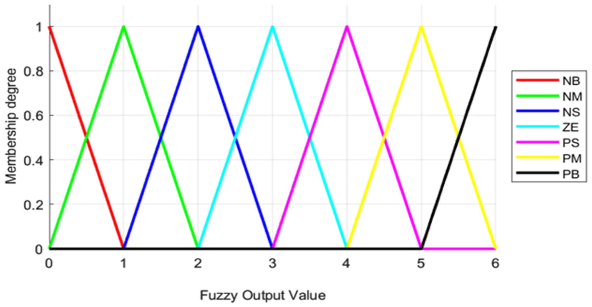
The normalized universes of discourse for E, EC, Kp, and Ki are [0, 6]. Each variable is described by seven linguistic labels: negative big (NB), negative medium (NM), negative small (NS), zero (ZE), positive small (PS), positive medium (PM), and positive big (PB). In this nonnegative normalized implementation, the labels are retained as ordered rule-base levels rather than literal signed physical values. The 49 rules for Kp and Ki are given in Table 2 and Table 3. MATLAB Fuzzy Logic Toolbox version 23.2 was used to verify the rule surfaces, while the embedded implementation uses the same fixed membership vertices and lookup rules.
Figure 4 and Figure 5 show the triangular membership functions for the normalized fuzzy inputs and outputs Kp and Ki over the universe [0, 6]. The triangular membership-function vertices are NB [0, 0, 1], NM [0, 1, 2], NS [1, 2, 3], ZE [2, 3, 4], PS [3, 4, 5], PM [4, 5, 6], and PB [5, 6, 6]. The shoulder functions at the two ends avoid extrapolation outside the normalized domain. Before fuzzification, physical errors are multiplied by input scaling factors; after defuzzification, the normalized outputs are mapped to bounded positive gain ranges.
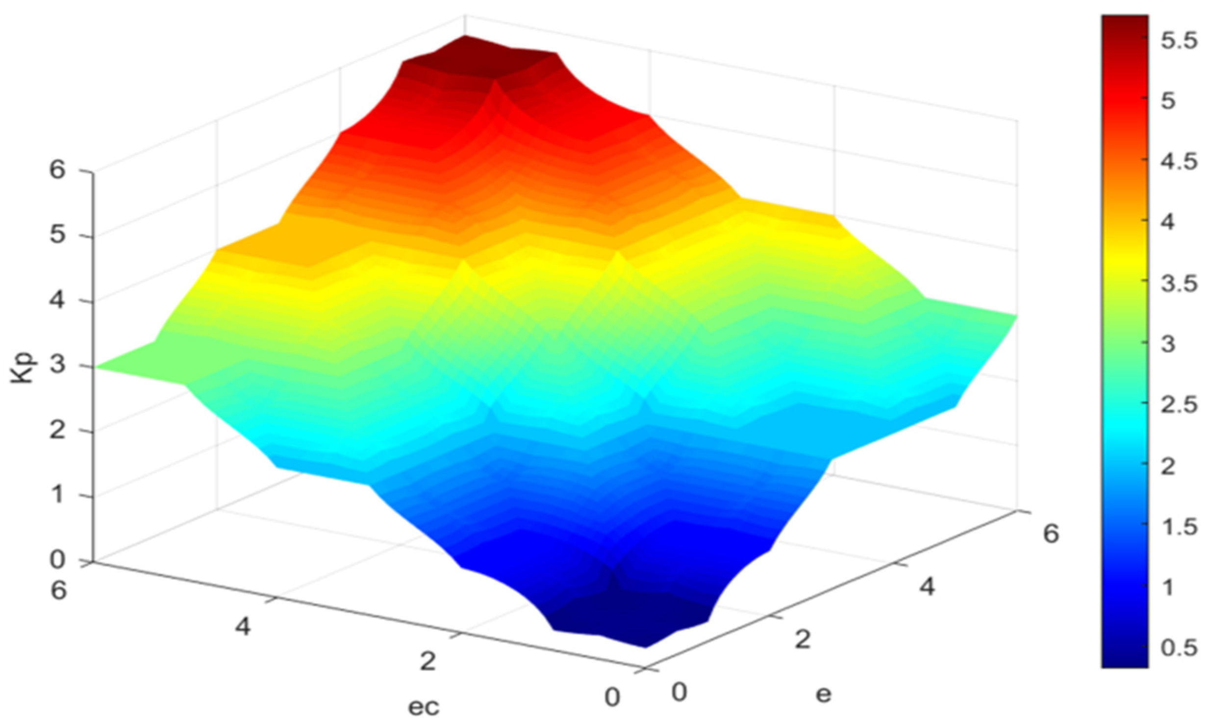
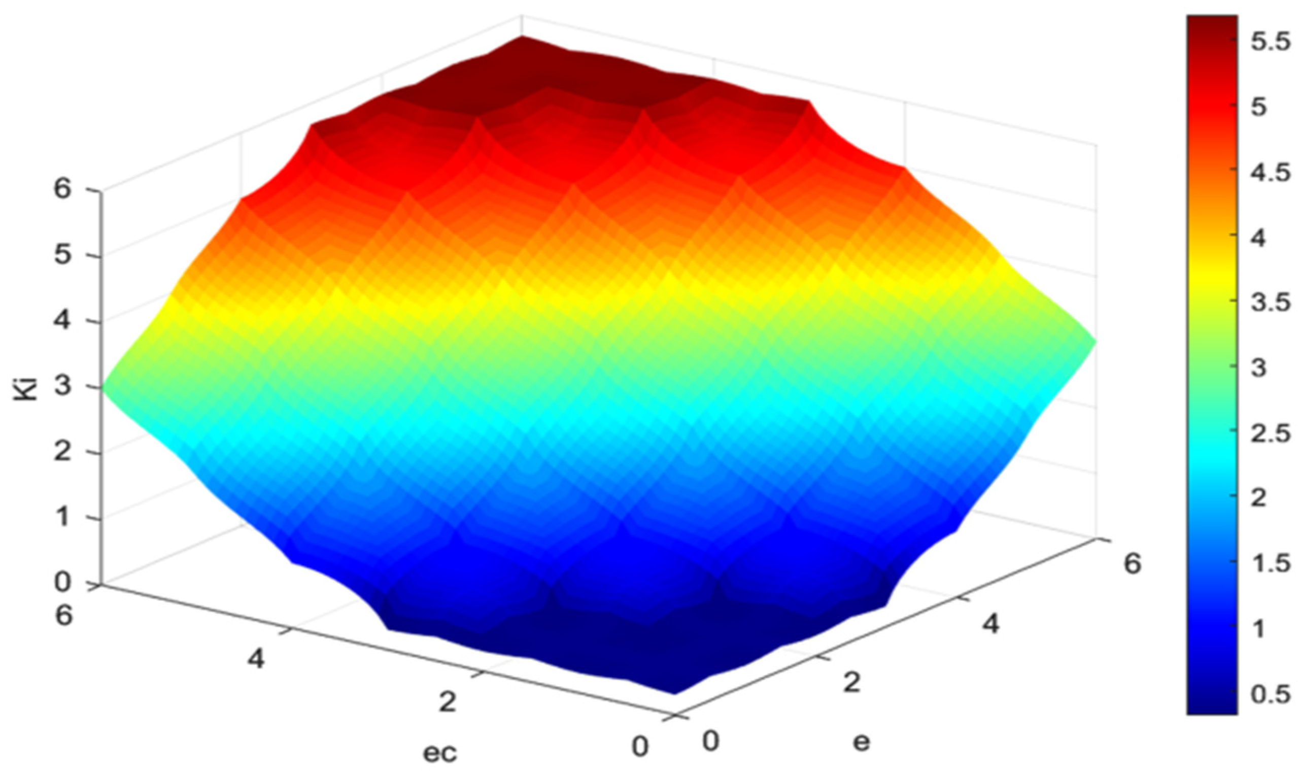
The rule base is designed so that larger or increasing errors produce stronger correction, while small and decreasing errors produce lower gains to suppress steady-state ripple. Figure 6 and Figure 7 show the resulting input–output surfaces for Kp and Ki.
Through fuzzy inference, the output gain adjustment values are obtained and subsequently converted into precise control variables through defuzzification. Common defuzzification methods include the maximum membership degree method, centroid method, and weighted average method. Although the centroid method yields a relatively smooth output, its calculation is more difficult. The weighted average method is generally more commonly used in industry. Therefore, the maximum membership degree method is adopted due to its lower computational complexity and suitability for real-time implementation.

3. Control System Structure

3.1. Simulation and Experimental Platform

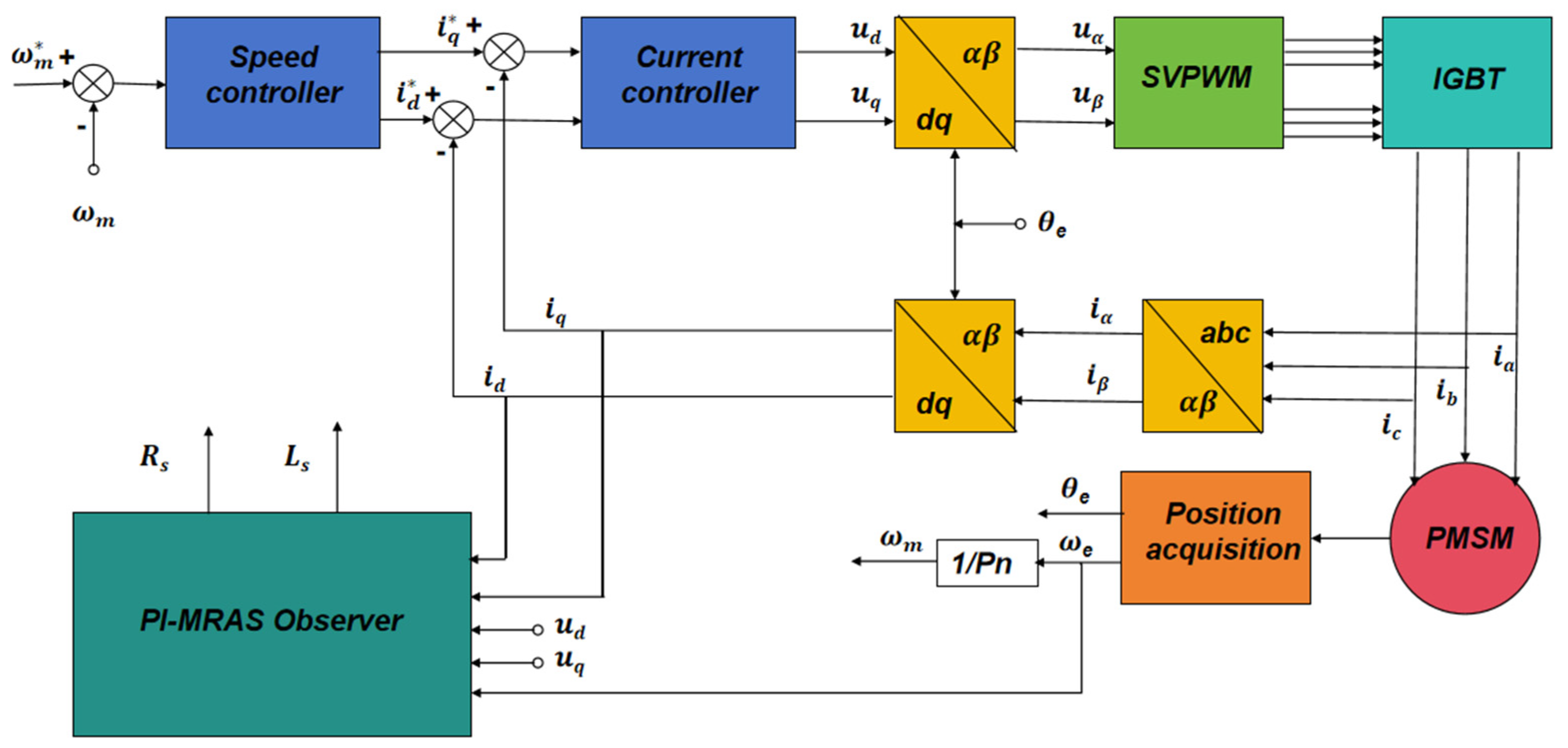
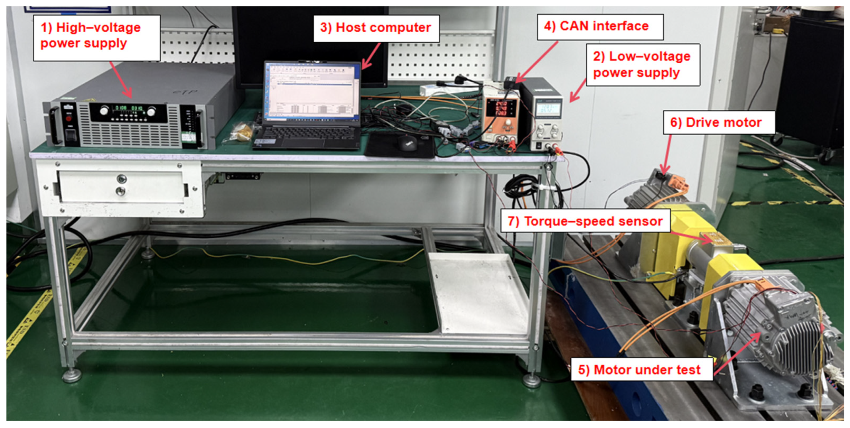
To verify the effectiveness of the proposed Fuzzy PI-MRAS-based online parameter identification method for PMSM drives, a PMSM parameter identification simulation model was built using MATLAB R2023b/Simulink. The PMSM motor parameters selected for the simulation are shown in Table 4, and the controller, adaptive law, and fuzzy inference parameters are shown in Table 5. Figure 8 illustrates the overall simulation framework, including the PMSM model, control system, and proposed observer model, current acquisition and coordinate transformation modules, the Fuzzy PI-MRAS parameter identification module, and a parameter comparison and analysis module. It can collect the speed, dq-axis voltage, and current signals during motor operation in real-time and input them into the identification module to complete the online estimation of Rs and Ls. Figure 9 shows the experimental platform of the PMSM online parameter identification system.
The digital control platform is based on an Infineon TC233 microcontroller. The FOC algorithm and the proposed Fuzzy PI-MRAS observer are implemented in the same digital control platform. The PWM switching frequency is set to 15 kHz, and the control period is 100 us.
The fuzzy tuning layer has two inputs, seven triangular membership functions per input, and two 49-rule output tables. Because adjacent triangular sets overlap, no more than two memberships are nonzero for each input and, therefore, no more than four rules are active at one sample. The implementation requires normalization, membership evaluation, minmax rule aggregation, a maximum-membership selection, output scaling, and saturation. The workload is constant per sample and has O (1) complexity; it does not require covariance propagation, matrix inversion, iterative optimization, or online training.
The measured torque and speed signals were used to verify the operating condition of the PMSM drive system during load disturbance and rated-load experiments. The identified motor parameters, d-q-axis currents and voltages, rotor speed, and load torque are transmitted to the host computer through the controller area network (CAN) interface. The recorded signals are saved in the comma-separated values (CSV) format and then imported into MATLAB for post-processing, error calculation, and figure plotting. Representative oscillograms of phase currents, speed, torque, and identified parameters are captured using a digital storage oscilloscope.
The integral gains used in this study are relatively large because the adaptation mechanism estimates slowly varying electrical parameters rather than tracking fast dynamic states. A larger integral gain improves the accumulation of parameter-error information and accelerates convergence during transient operation. Meanwhile, the fuzzy gain scheduling mechanism decreases the effective integral gain when the estimation error approaches zero, thereby reducing steady-state oscillations and maintaining identification accuracy.

3.2. Determination of Reference Parameter Values

To provide independent reference values for evaluating the identification results, the motor parameters were measured before the online identification experiments.
The Rs was determined by measuring the line-to-line resistance between two motor terminals using a precision digital multimeter. Multiple measurements were performed after the motor reached thermal equilibrium, and the average phase resistance was obtained according to the winding connection.
The Ls was measured using a precision LCR (inductance, capacitance, and resistance) meter. Measurements were carried out at different rotor positions, and the average measured value was used as the reference Ls.

3.3. Experimental Test Cases and Result Analysis

To compare the identification performance of the traditional PI-MRAS, the proposed Fuzzy PI-MRAS and the EKF algorithm, three experimental test cases were designed according to the rated operating condition, speed variation, and load variation of the PMSM drive system.
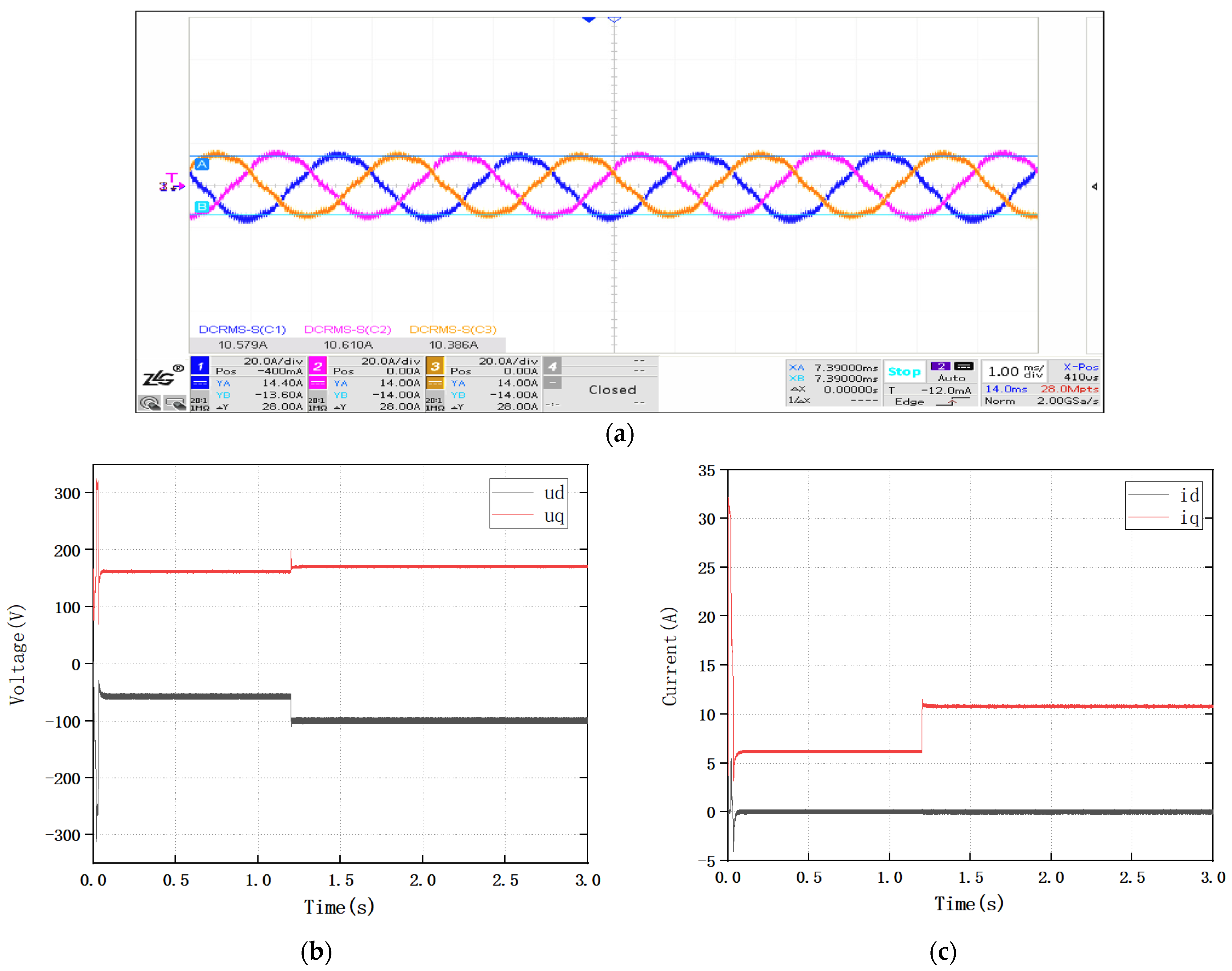
Specifically, Case 1 was conducted under the rated speed and rated load, namely, 2000 r/min and 10 N·m, to verify the identification accuracy under the rated operating condition.
Case 2 was designed as a load-variation test at a constant speed of 2000 r/min. The load torque was initially set to 5 N·m and then increased to 10 N·m at 1.2 s.
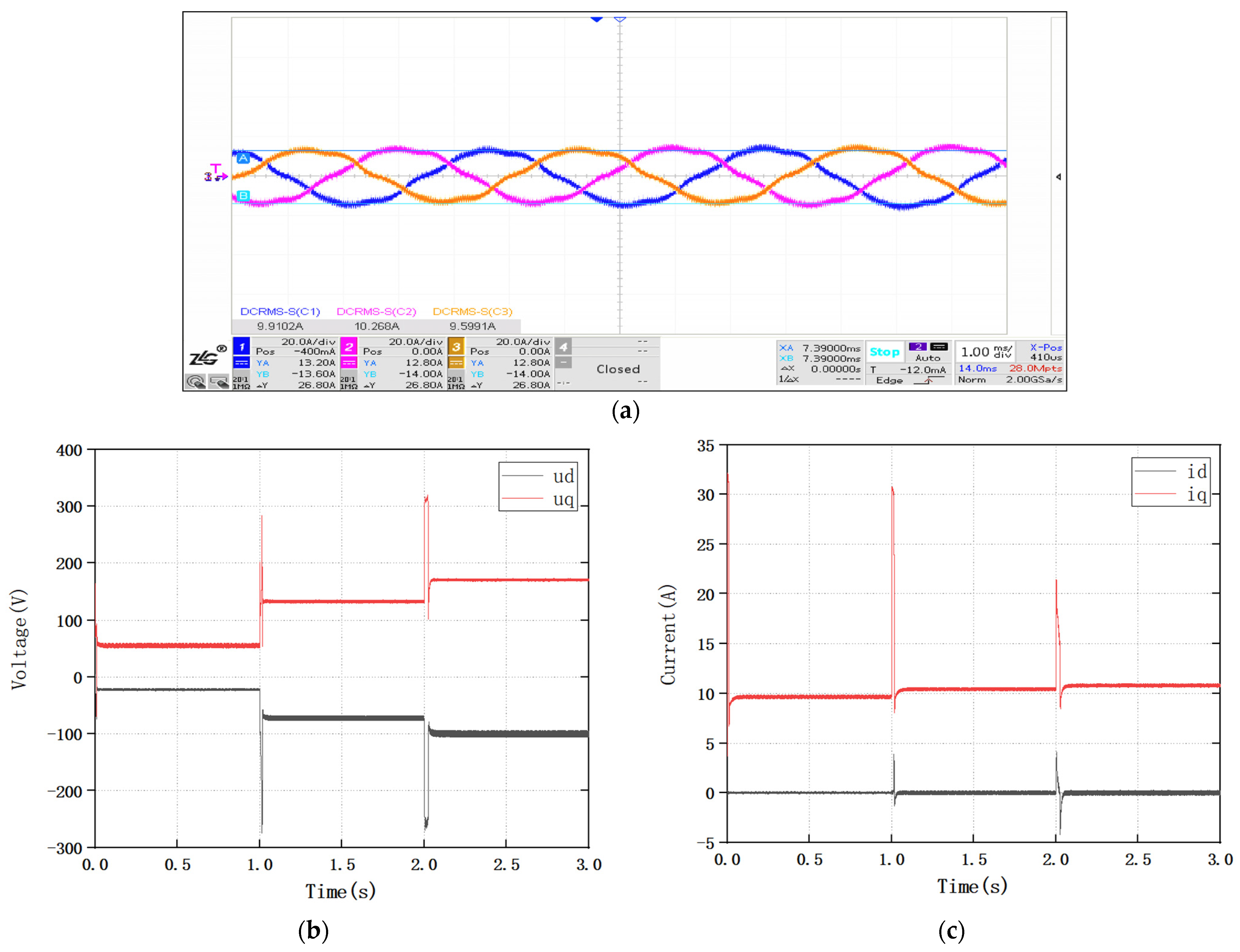
Case 3 was designed as a variable-speed test under a constant load torque of 10 N·m. In this case, the initial speed was set to 500 r/min, then switched to 1500 r/min at 1.0 s, and finally switched to 2000 r/min at 2.0 s.
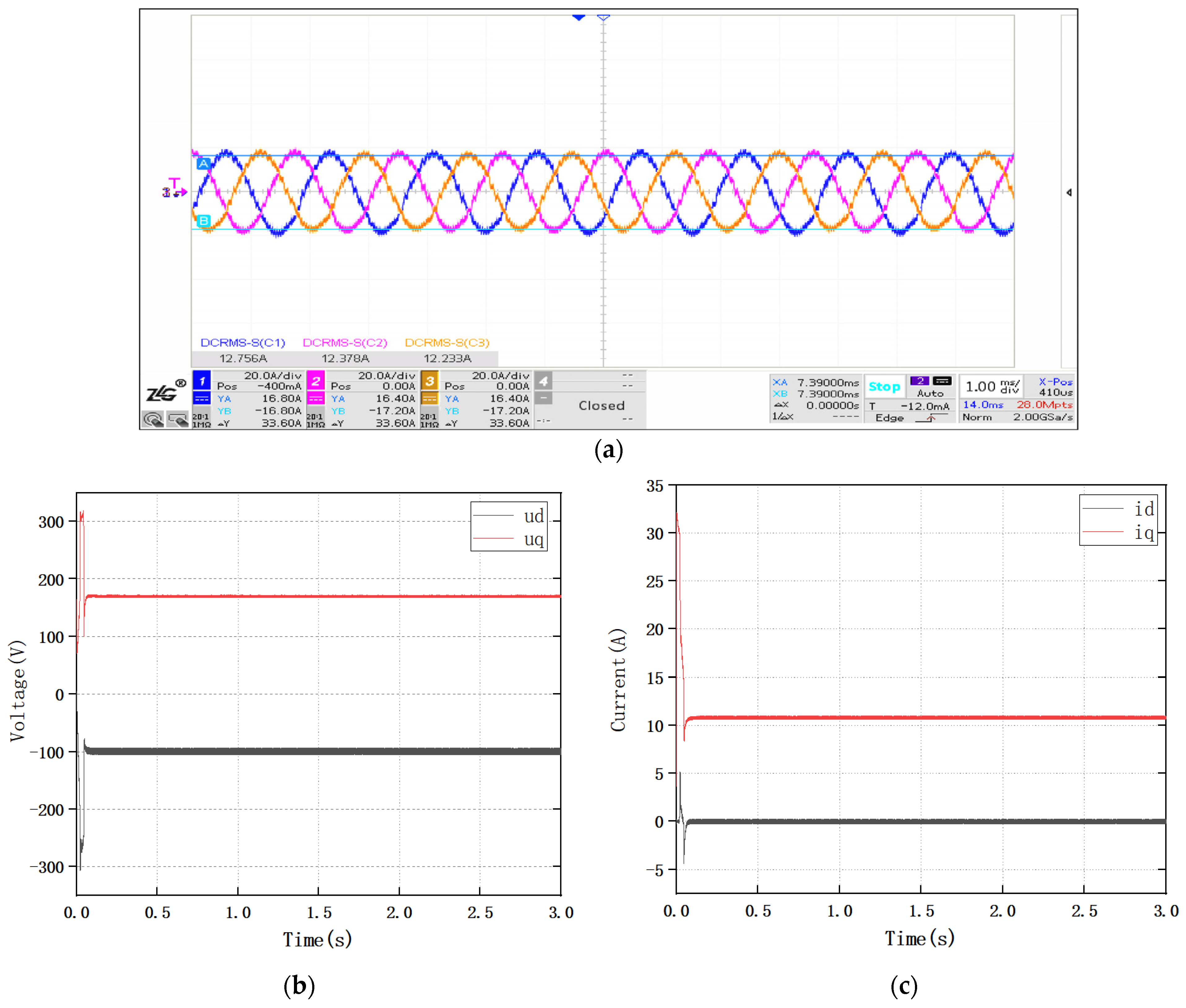
For each test case, the three-phase current oscillograms, d- and q-axes currents, d- and q-axes voltages, and online identification results of Rs, Ls were recorded. The phase-current waveforms were used to verify the actual electrical operating state of the motor, while the dq-axis current and voltage responses were used to evaluate the dynamic behavior of the control system during speed and load transitions. The identification results of the traditional PI-MRAS and the Fuzzy PI-MRAS were compared with the reference parameter values to evaluate the convergence performance and steady-state accuracy.
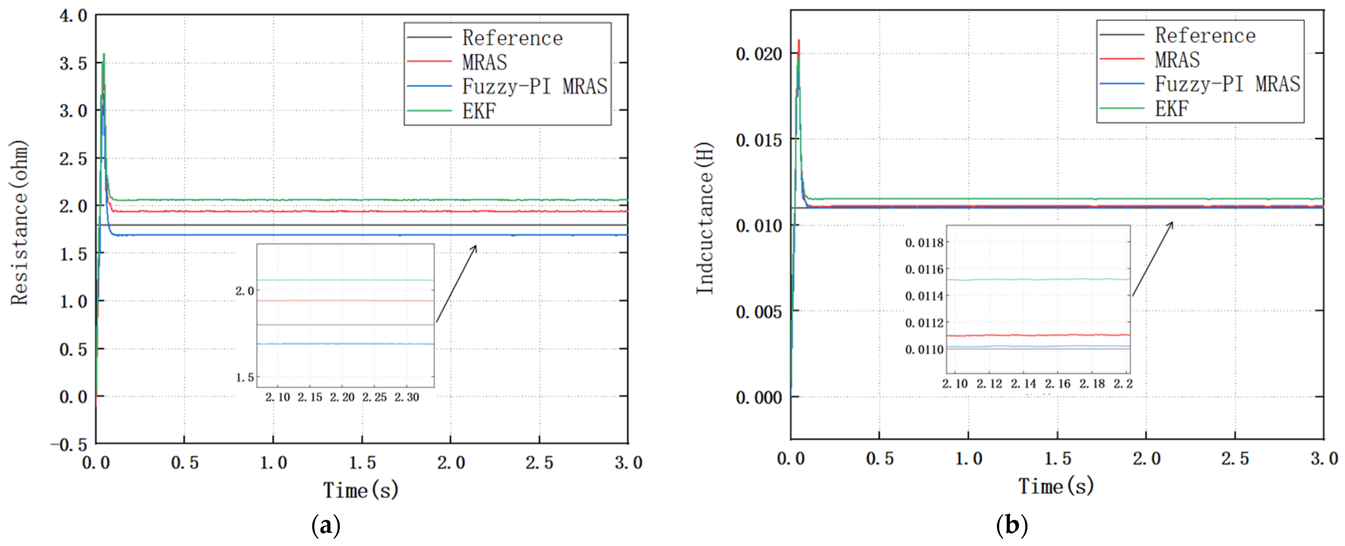
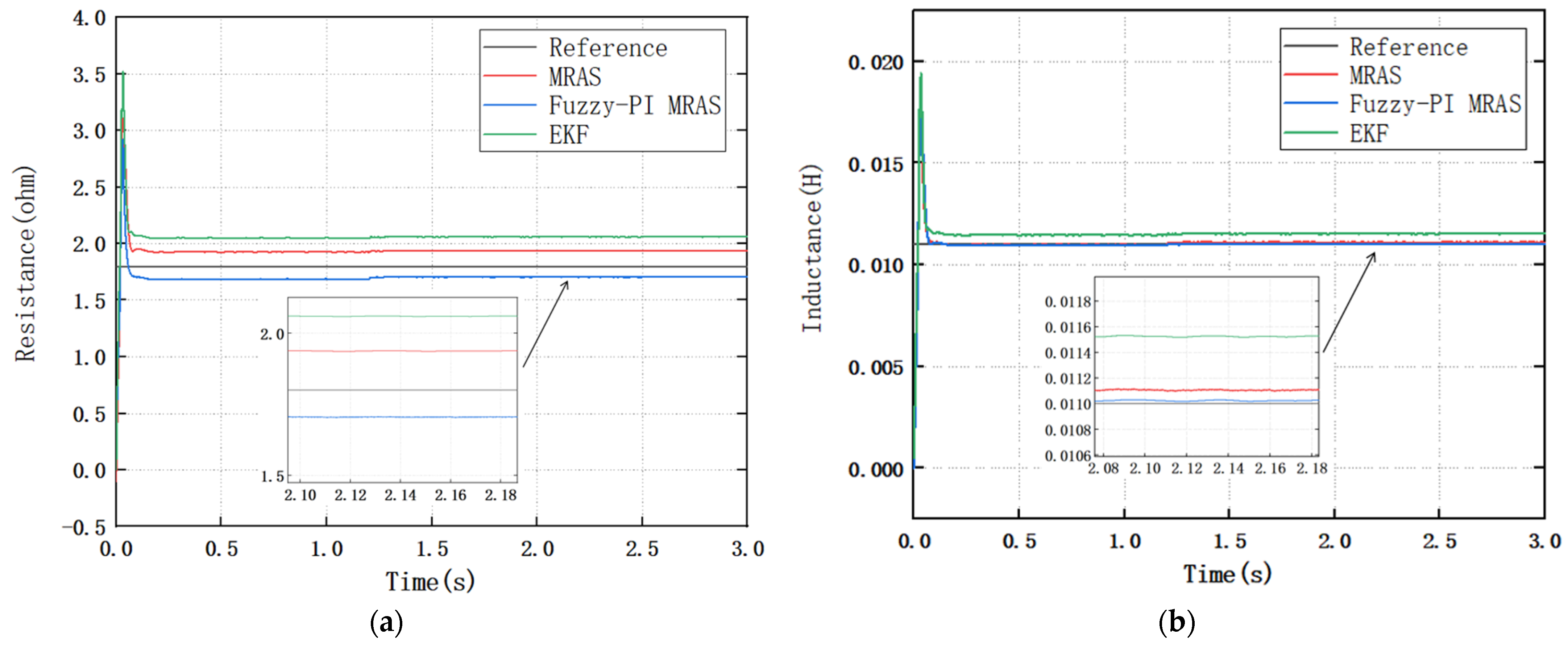
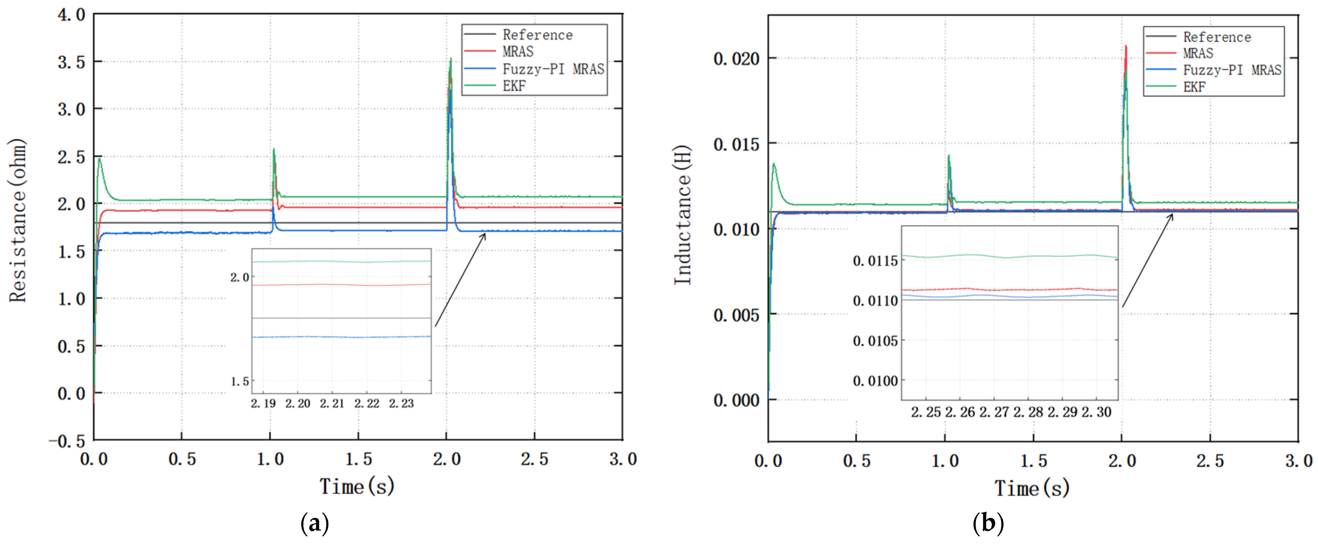
The experimental results in Figure 10, Figure 11, Figure 12, Figure 13, Figure 14 and Figure 15 are organized according to the three test cases. Figure 10 and Figure 11 correspond to Case 1, namely, the rated-speed and rated-load condition. Figure 12 and Figure 13 correspond to Case 2, namely, the load-variation condition at a constant speed. Figure 14 and Figure 15 correspond to Case 3, namely, the variable-speed condition under a constant load.

3.4. Non-Ideal Effects and Practical Limitations

Temperature variation primarily changes Rs and is, therefore, an intended target of the observer. However, the reference resistance and the electrical model must use a consistent temperature basis, and rapid thermal gradients can violate the slow-variation assumption. Magnetic saturation makes Ls dependent on the current magnitude and rotor position; under strong saturation, the single constant-inductance estimate should be interpreted as an effective local value rather than a globally constant physical parameter.
Inverter dead time, switching-device voltage drops, and dc-link-voltage error introduce a difference between commanded and applied dq-axis voltages. The observer may incorrectly attribute this voltage-model error to Rs or Ls, particularly at low speed and low current. Practical deployment should, therefore, include dead-time/device-drop compensation or use measured phase voltages. Current-sensor offset, quantization, and speed noise perturb both E and EC; filtering, a small error dead band, gain-rate limiting, and positive gain saturation can reduce noise-driven switching.
Parameter convergence also depends on excitation. When dq-axis voltage–current regressors are weakly excited or highly correlated, a small current-model error does not guarantee a unique convergence of both Rs and Ls. The three laboratory cases demonstrate feasibility within the tested operating range, but temperature sweeps, controlled saturation tests, injected measurement noise, inverter-nonlinearity compensation, repeated trials, and long-duration operation were not comprehensively evaluated. These conditions define the boundary of the present conclusions and the priorities for future validation.

3.5. Experimental Conclusion

The experimental results show that, compared with the traditional PI-MRAS algorithm, the proposed Fuzzy PI-MRAS algorithm and the EKF algorithm achieve higher-precision online parameter identification for PMSMs under the rated operating condition, variable-speed condition, and load-variation condition. Under the rated speed and rated loads of 2000 r/min and 10 N·m, the proposed method maintains stable identification accuracy. During the variable-speed test from 500 r/min to 1500 r/min and then to 2000 r/min, and during the load-variation test from 5 N·m to 10 N·m, the Fuzzy PI-MRAS method shows smaller transient fluctuation and better steady-state tracking performance.
For each operating condition, the steady-state identification values of Rs and Ls were extracted after the transient process. The identification errors were calculated with respect to the reference parameter values. Table 6 and Table 7 provide a quantitative statistical analysis of the identification performance. The steady-state identification values are presented as the mean ± standard deviation, where the standard deviation reflects the fluctuation of the estimated parameters during steady-state operation.
The proposed Fuzzy PI-MRAS achieves the smallest standard deviation among the three methods, indicating lower parameter fluctuation and improved steady-state stability. Compared with conventional PI-MRAS and EKF, the fuzzy gain scheduling mechanism reduces excessive adaptive correction when the estimation error approaches zero, thereby improving the smoothness of the identified inductance.

4. Conclusions

To improve the adaptability and disturbance rejection of conventional PI-MRAS methods for online PMSM parameter identification, this paper proposes a Fuzzy PI-MRAS observer in which the gains of the adaptive law are adjusted online. The method was evaluated through theoretical analysis, simulation, and laboratory experiments under the operating conditions considered in this study.
The proposed method introduces a fuzzy gain-tuning mechanism into the MRAS adaptive law. The absolute value of the identification error and its rate of change are used as the inputs of the fuzzy controller to update the proportional and integral gains. This mechanism reduces the dependence on fixed PI gains and improves the response of the observer to changes in motor speed, load torque, and motor parameters within the tested operating range.
The comparative results indicate that the proposed method provides more accurate estimates of Rs and Ls than the conventional PI-MRAS method. According to Table 6 and Table 7, the Rs identification error decreases from 8.1% to 3.8%, the Ls identification error decreases from 0.91% to 0.18%. The results demonstrate the effectiveness of the proposed fuzzy gain-adjustment strategy under the investigated speed and load conditions.
Nevertheless, these results should be interpreted within the experimental conditions and reference-parameter measurement procedures described in this paper. The proposed observer has a relatively simple structure and is suitable for real-time implementation on a digital motor-control platform. It, therefore, has potential for PMSM drive systems requiring online parameter information. However, its application to electric vehicle traction systems, industrial servo drives, and robotic systems requires further system-level validation.
The present study is limited to a laboratory PMSM platform and a finite set of operating conditions. The influences of temperature variation, magnetic saturation, inverter nonlinearity, measurement noise, and long-term operation have not yet been comprehensively investigated. Future work will include experiments over broader operating cycles, independent verification of the reference parameter values, and integration with RLS or sliding-mode observers for simultaneous parameter identification and state estimation.

Author Contributions

Conceptualization, J.N. (Jishun Neng); methodology, J.N. (Jishun Neng); software, B.H.; validation, S.X.; formal analysis, X.J.; investigation, J.N. (Jishun Neng); resources, B.H.; writing—original draft preparation, X.W.; writing—review and editing, B.H.; visualization, J.N. (Jingbin Niu); supervision, J.N. (Jishun Neng). All authors have read and agreed to the published version of the manuscript.

Funding

This research received no external funding.

Data Availability Statement

The data presented in this study are available upon request from the corresponding author due to project data confidentiality agreement.

Conflicts of Interest

Jingbin Niu is an employee of Jiangsu Firstwise New Energy Technology Co., Ltd. Jingbin Niu declares that this employment does not constitute a commercial or financial conflict of interest related to the work under consideration. The remaining authors declare that the research was conducted in the absence of any commercial or financial relationships that could be construed as a potential conflict of interest. Jiangsu Firstwise New Energy Technology Co., Ltd., was not involved in the study design, collection, analysis, interpretation of data, the writing of this article, or the decision to submit it for publication.

References

  1. Zhu, Z.Q.; Liang, D.; Liu, K. Online Parameter Estimation for Permanent Magnet Synchronous Machines: An Overview. IEEE Access 2021, 9, 59059–59084. [Google Scholar] [CrossRef]
  2. Wang, Q.; Wang, G.; Zhao, N.; Zhang, G.; Cui, Q.; Xu, D. An Impedance Model-Based Multiparameter Identification Method of PMSM for Both Offline and Online Conditions. IEEE Trans. Power Electron. 2021, 36, 727–738. [Google Scholar] [CrossRef]
  3. Yu, Y.; Huang, X.; Li, Z.; Wu, M.; Shi, T.; Cao, Y.; Yang, G.; Niu, F. Full Parameter Estimation for Permanent Magnet Synchronous Motors. IEEE Trans. Ind. Electron. 2022, 69, 4376–4386. [Google Scholar] [CrossRef]
  4. Yu, H.; Wang, J.; Xin, Z. Model Predictive Control for PMSM Based on Discrete Space Vector Modulation with RLS Parameter Identification. Energies 2022, 15, 4041. [Google Scholar] [CrossRef]
  5. Yuan, T.; Chang, J.; Zhang, Y. Parameter Identification of Permanent Magnet Synchronous Motor with Dynamic Forgetting Factor Based on H∞ Filtering Algorithm. Actuators 2023, 12, 453. [Google Scholar] [CrossRef]
  6. Li, X.; Kennel, R. General Formulation of Kalman-Filter-Based Online Parameter Identification Methods for VSI-Fed PMSM. IEEE Trans. Ind. Electron. 2021, 68, 2856–2864. [Google Scholar] [CrossRef]
  7. Yang, H.; Yang, R.; Hu, W.; Huang, Z.; Zhang, Y.; Wang, Z. FPGA-Based Sensorless Speed Control of PMSM Using Enhanced Performance Controller Based on the Reduced-Order EKF. IEEE J. Emerg. Sel. Top. Power Electron. 2021, 9, 289–301. [Google Scholar] [CrossRef]
  8. Zwerger, T.; Mercorelli, P. Using a Bivariate Polynomial in an EKF for State and Inductance Estimations in the Presence of Saturation Effects to Adaptively Control a PMSM. IEEE Access 2022, 10, 111545–111553. [Google Scholar] [CrossRef]
  9. Liu, K.; Zhang, Q.; Zhu, Z.Q.; Zhang, J.; Shen, A.W.; Stewart, P. Comparison of Two Novel MRAS Based Strategies for Identifying Parameters in Permanent Magnet Synchronous Motors. Int. J. Autom. Comput. 2010, 7, 516–524. [Google Scholar] [CrossRef]
  10. Wu, C.; Zhao, Y.; Sun, M. Enhancing Low-Speed Sensorless Control of PMSM Using Phase Voltage Measurements and Online Multiple Parameter Identification. IEEE Trans. Power Electron. 2020, 35, 10700–10710. [Google Scholar] [CrossRef]
  11. Singh, V.; Majumder, M.G.; Rajashekara, K.; Reddy, S.R.P. Parameter Estimation for Sensorless Position Control of PMSM Drives with Long Cables in Subsea Applications. IEEJ J. Ind. Appl. 2023, 12, 303–311. [Google Scholar] [CrossRef]
  12. Cao, Y.; Ren, X.; Guo, Q.; Zhan, H.; Li, W.; Wu, G.; Long, Q. Model Reference Adaptive System of Permanent Magnet Synchronous Motor Based on Current Residual Compensation Without Position Measurement. Actuators 2024, 13, 446. [Google Scholar] [CrossRef]
  13. Zhu, S.; Hu, K.; Lin, J.; Liu, Y.; Chen, H.; Wang, W.; Gao, J. Nonlinear Flux Linkage Observer with Model Reference Adaptive System for Improved Permanent Magnet Synchronous Motor Control. Actuators 2024, 13, 403. [Google Scholar] [CrossRef]
  14. Li, H.; Jian, X. Parameter Identification of Permanent Magnet Synchronous Motor Based on CGCRAO Algorithm. IEEE Access 2023, 11, 124319–124330. [Google Scholar] [CrossRef]
  15. Zhou, S.; Wang, D.; Li, Y. Parameter Identification of Permanent Magnet Synchronous Motor Based on Modified-Fuzzy Particle Swarm Optimization. Energy Rep. 2023, 9, 873–879. [Google Scholar] [CrossRef]
  16. Ahandani, M.A.; Noei, A.R.; Hajyad, A.H.; Kazem, H.A. Parameter Identification of Permanent Magnet Synchronous Motor Using Improved Particle Swarm Optimization. Appl. Intell. 2022, 52, 13082–13096. [Google Scholar] [CrossRef]
  17. Bui, M.X.; Dutta, R.; Rahman, M.F. Application of Deep Learning in Parameter Estimation of Permanent Magnet Synchronous Machines. IEEE Access 2024, 12, 40710–40721. [Google Scholar] [CrossRef]
  18. Brosch, A.; Wallscheid, O.; Böcker, J. Long-Term Memory Recursive Least Squares Online Identification of Highly Utilized Permanent Magnet Synchronous Motors for Finite-Control-Set Model Predictive Control. IEEE Trans. Power Electron. 2023, 38, 1451–1467. [Google Scholar] [CrossRef]
  19. Liu, Z.H.; Nie, J.; Wei, H.L.; Chen, L.; Li, X.H.; Lv, M.Y. Switched PI Control Based MRAS for Sensorless Control of PMSM Drives Using Fuzzy-Logic-Controller. IEEE Open J. Power Electron. 2022, 3, 368–381. [Google Scholar] [CrossRef]
  20. Bıçak, A.; Gelen, A. Modified Super-Twisting Algorithm-Based Model Reference Adaptive Observer for Sensorless Control of the Interior Permanent-Magnet Synchronous Motor in Electric Vehicles. Machines 2023, 11, 871. [Google Scholar] [CrossRef]
  21. Khanh, P.Q.; Anh, H.P.H. Novel Sensorless PMSM Speed Control Using Advanced Fuzzy MRAS Algorithm. Arab. J. Sci. Eng. 2022, 47, 14531–14542. [Google Scholar] [CrossRef]
  22. Sun, H.; Zhang, X.; Liu, X.; Xiong, S. Adaptive Robust Sensorless Control for PMSM Based on Improved Back EMF Observer and Extended State Observer. IEEE Trans. Ind. Electron. 2024, 71, 8688. [Google Scholar] [CrossRef]
  23. Niu, F.; Chen, X.; Huang, S.; Huang, X.; Wu, L.; Li, K.; Fang, Y. Model Predictive Current Control with Adaptive-Adjusting Timescales for PMSMs. CES Trans. Electr. Mach. Syst. 2021, 5, 108–117. [Google Scholar] [CrossRef]
  24. Brosch, A.; Wallscheid, O.; Böcker, J. Torque and Inductances Estimation for Finite Model Predictive Control of Highly Utilized Permanent Magnet Synchronous Motors. IEEE Trans. Ind. Inform. 2021, 17, 8080–8091. [Google Scholar] [CrossRef]
  25. Sun, W.; Si, H.; Qiu, J.; Li, J. Research on Efficiency of Permanent-Magnet Synchronous Motor Based on Adaptive Algorithm of Fuzzy Control. Sustainability 2024, 16, 1253. [Google Scholar] [CrossRef]
  26. Wang, B.L.; Li, Z.X.; Li, Y.C.; Zhu, J.H. Fuzzy Sliding Mode Control of PMSM Based on PSO. IEICE Electron. Express 2023, 20, 20230346. [Google Scholar] [CrossRef]
Figure 1. MRAS classical control algorithm model.
Wevj 17 00417 g001
Figure 2. Nonlinear time-varying feedback system.
Wevj 17 00417 g002
Figure 3. Fuzzy gain-scheduling structure for the PI-MRAS adaptation law.
Wevj 17 00417 g003
Figure 4. Membership function for input variables E and EC.
Wevj 17 00417 g004
Figure 5. Membership function for output variables Kp and Ki.
Wevj 17 00417 g005
Figure 6. 3D surface plot for Kp.
Wevj 17 00417 g006
Figure 7. 3D surface plot for Ki.
Wevj 17 00417 g007
Figure 8. Simulation model diagram.
Wevj 17 00417 g008
Figure 9. Experimental platform for PMSM online parameter identification: (1) high-voltage power supply, (2) low-voltage auxiliary power supply, (3) host computer, (4) CAN interface, (5) motor under test, (6) drive motor, and (7) torque–speed sensor.
Wevj 17 00417 g009
Figure 10. (a) Oscillograms of the three-phase currents under a rated speed and rated load; (b) d- and q-axes voltage responses under the tested operating conditions; (c) d- and q-axes current responses under the tested operating conditions.
Wevj 17 00417 g010
Figure 11. (a) Comparison of the online Rs identification performance among the conventional MRAS, EKF, and the proposed Fuzzy PI-MRAS observer under a rated speed and rated load; (b) comparison of the online Ls identification performance among the conventional MRAS, EKF, and proposed Fuzzy PI-MRAS observer under a rated speed and rated load.
Wevj 17 00417 g011
Figure 12. (a) Oscillograms of the three-phase currents under the load-variation condition; (b) d- and q-axes voltage responses under the load-variation condition; (c) d- and q-axes current responses under the load-variation condition.
Wevj 17 00417 g012
Figure 13. (a) Comparison of the online Rs identification performance among the conventional MRAS, EKF, and proposed Fuzzy PI-MRAS observer under the load-variation condition; (b) comparison of the online Ls identification performance among the conventional MRAS, EKF, and proposed Fuzzy PI-MRAS observer under the load-variation condition.
Wevj 17 00417 g013
Figure 14. (a) Oscillograms of the three-phase currents under the variable-speed condition; (b) d- and q-axes voltage responses under the variable-speed condition; (c) d- and q-axes current responses under the variable-speed condition.
Wevj 17 00417 g014
Figure 15. (a) Comparison of the online Rs identification performance among the conventional MRAS, EKF, and proposed Fuzzy PI-MRAS observer under the variable-speed condition; (b) comparison of the online Ls identification performance among the conventional MRAS, EKF, and proposed Fuzzy PI-MRAS observer under the variable-speed condition.
Wevj 17 00417 g015
Table 1. Qualitative comparison with representative recent MRAS-related PMSM methods.
MethodEstimated/Observed QuantitiesAdaptation MechanismRelative Online BurdenValidationMain Distinction/Limitation
Liu et al. [19]Speed, position, and RsFuzzy selection among switched PI mechanismsLow–moderateSimulation and experimentImproves sensorless robustness; does not target simultaneous Rs–Ls identification
Bıçak and Gelen [20]Rotor speed/positionAdaptive super-twisting MRASModerateSimulation under EV drive cyclesStrong disturbance performance; no online electrical-parameter identification
Cao et al. [12]; Zhu et al. [13]Speed/position or flux-related statesResidual compensation or nonlinear flux observer combined with MRASModerateSimulation and/or experimentEnhanced sensorless control; different target variables and observer structures
Proposed methodRs and LsPopov-derived PI-MRAS with fuzzy online gain schedulingLow–moderate; fixed-rule inferenceSimulation and laboratory experimentSimultaneous Rs–Ls estimation with explicit gain scheduling; limited non-ideal-condition validation
Table 2. Fuzzy rule table for Kp.
KpEC
NBNMNSZEPSPMPB
ENBNBNBNMNSNSZEZE
NMNBNBNMNSZEZEZE
NSNMNMNSNSZEPSPS
ZENSNSNSZEPSPSPS
PSNSNSZEPSPSPMPM
PMNSZEZEPSPMPBPB
PBZEZEPSPSPMPBPB
Table 3. Fuzzy rule table for Ki.
KiEC
NBNMNSZEPSPMPB
ENBNBNBNBNBNMNSZE
NMNBNBNBNMNSZEPS
NSNBNBNMNSZEPSPM
ZENBNMNSZEPSPMPB
PSNMNSZEPSPMPBPB
PMNSZEPSPMPBPBPB
PBZEPSPMPBPBPBPB
Table 4. Controller, adaptive law, and fuzzy inference parameters.
CategoryParameterValue
Current PIKpd, Kpq27.6
Current PIKid, Kiq4524
Rs adaptationKpR00.80
Rs adaptationKiR080
Ls adaptationKpL00.40
Ls adaptationKiL040
Input scalingKe10
Input scalingKec50
Output scalingSpR, SiR0.40, 40
Output scalingSpL, SiL0.20, 20
Input/output universe-[−1, 1]
Membership functions-7 triangular MFs
Defuzzification-MOM
Error-rate filter α 0.833
Gain smoothingβ0.10
Table 5. Simulation motor parameters.
Motor ParametersNumerical Value
Power supply voltage/V380
Switching frequency/kHz15
Rs/Ω1.8
Ls/H0.011
Permanent magnet flux linkage/Wb0.18
Motor pole pair number4
Rated speed/r·min−12000
Rated Torque/N·m10
Table 6. Statistical analysis of the Rs identification results.
ParameterReference Value (ohm)Mean Value (ohm)Standard
Deviation (ohm)
Error (%)
MRAS1.81.946 ± 0.0060.0068.1
FuzzyPI-MRAS1.81.732 ± 0.0030.0033.8
EKF1.82.031 ± 0.0080.00812.8
Table 7. Statistical analysis of the Ls identification results.
ParameterReference Value (H)Mean Value (H)Standard
Deviation (H)
Error (%)
MRAS0.011000.01110 ± 0.000080.000080.91
FuzzyPI-MRAS0.011000.01102 ± 0.000030.000030.18
EKF0.011000.01152 ± 0.000120.000124.73
Disclaimer/Publisher’s Note: The statements, opinions and data contained in all publications are solely those of the individual author(s) and contributor(s) and not of MDPI and/or the editor(s). MDPI and/or the editor(s) disclaim responsibility for any injury to people or property resulting from any ideas, methods, instructions or products referred to in the content.