1. Introduction
Switched reluctance motors (SRMs) have attracted considerable attention in the automotive industry due to their inherently simple construction, broad speed regulation range, and excellent operational stability [
1]. However, their distinctive doubly salient structure introduces pronounced nonlinear electromagnetic behaviors, strong inter-phase coupling, and saturation-related issues, all of which lead to significant torque ripple during operation [
2,
3]. These factors contribute to reduced system efficiency and limit the broader adoption of SRMs in vehicular applications [
4,
5].
Among various methods for suppressing torque ripple in SRMs, torque sharing functions (TSFs) are widely recognized as an effective approach for torque allocation during phase commutation. Ye et al. [
6] and Li et al. [
7] adopted TSFs, which employ predefined functions to smoothly distribute interphase torque reference values during the commutation interval. This approach has been shown to significantly mitigate torque ripple in SRMs within the commutation region of SRMs [
8,
9]. Owing to their simple implementation and clear physical meaning, TSFs are commonly used in SRM drives as a basic reference generation method [
10,
11]. However, the control performance of TSF-based schemes still depends strongly on the subsequent control strategy, especially under nonlinear operating conditions and external disturbances.
To further enhance control performance, MPC has attracted considerable attention because of its advantages in online optimization, constraint handling, and fast feedback regulation [
12]. In SRM drive applications, MPC has been used to improve current tracking, torque control accuracy, and overall dynamic performance. For example, Ge et al. [
13] investigated an MPC strategy for suppressing bus voltage fluctuations, while Shahjahan et al. [
14] improved current tracking precision and torque performance through current prediction. Li et al. [
15] introduced a direct torque prediction approach to enhance control accuracy. In addition, Ding et al. [
16] proposed a lookup-table-based MPC scheme to simplify real-time implementation. Although these studies demonstrate the potential of MPC in SRM control, many MPC-based methods still depend heavily on model accuracy. Since SRMs exhibit pronounced magnetic nonlinearity and parameter sensitivity, prediction errors caused by parameter mismatch may degrade current and torque control performance. Moreover, the effectiveness of MPC is inherently constrained by its sampling and optimization cycle, which may reduce its responsiveness under sudden speed or load disturbances. Although some improved strategies have been proposed for specific operating conditions, such as the enhanced commutation strategy reported in [
17], their applicability remains relatively limited.
Compared with MPC, DITC provides a more direct and faster mechanism for transient torque regulation. By taking instantaneous torque as the control target, DITC can quickly generate compensation actions through torque hysteresis control and a predefined switching table, without requiring complex online optimization [
18,
19,
20]. Therefore, when a sudden torque deviation occurs, DITC can respond rapidly and effectively suppress transient torque fluctuations on a very short timescale [
21,
22]. Nevertheless, DITC also has inherent limitations. Its performance is highly dependent on the hysteresis bandwidth setting: a narrow hysteresis band improves torque control accuracy but increases switching frequency, whereas a wide hysteresis band reduces switching stress at the expense of dynamic precision. As a result, DITC alone is not always suitable for simultaneously achieving high steady-state performance and robust transient response.
To overcome the individual limitations of MPC and DITC by leveraging their complementary strengths, this paper proposes an integrated control strategy that combines both methods. The approach utilizes TSF-generated reference torque as a unified command signal. Flux linkage and torque characteristics obtained via finite element analysis (FEA) are incorporated into MPC through a lookup table mechanism, improving the accuracy of torque and current predictions while reducing computational complexity. Furthermore, the MPC output is restructured to generate a fixed-frequency duty cycle, stabilizing the switching behavior of the power converter. Under sudden disturbances, the enhanced DITC module, equipped with an optimized hysteresis width, serves as a dynamic compensation loop. It is rapidly triggered upon detection of significant torque deviations—offering timely torque correction that MPC alone cannot provide due to sampling latency. Simulation results validate the efficacy of this cooperative control strategy, demonstrating improvements in both steady-state and dynamic performance.
2. Mathematical Model and Operating Principle of SRM
This section presents the mathematical model and operating principle of the SRM under study, which constitute the methodological foundation for the subsequent control design and analysis.
The SRM is characterized by a doubly salient pole structure and operates based on the principle of minimum magnetic reluctance [
23]. Common rotor–stator configurations include 8/6 and 12/8 pole structures, which contribute to its unique electromagnetic behavior. To facilitate accurate control design—particularly in the context of TSFs and MPC—this section derives a comprehensive coupled model of the SRM. The model integrates nonlinear magnetic flux characteristics, current dynamics, and mechanical motion, and is developed in accordance with the principles of energy conservation and Kirchhoff’s voltage law.
The voltage balance equation for the
k-th phase winding is expressed as follows:
where
represents the voltage of the
k-th phase motor winding;
represents the resistance of the
k-th phase winding;
represents the current of the
k-th phase winding; and
represents the flux linkage of the
k-th phase winding.
The flux linkage
of the
k-th phase winding of the motor can be expressed as a function of the winding current
and the rotor position angle
, as follows:
Ignoring the influence of phase-to-phase mutual inductance, the voltage balance equation of the SRM can be expressed as:
The mechanical dynamics of the motor are governed by the following torque balance equation:
where
represents the total electromagnetic torque of the motor;
represents the rotor angular velocity;
represents the moment of inertia;
represents the load torque; and
represents the damping coefficient.
The electromagnetic torque generated by the system is intrinsically linked to both the magnetic stored energy
and the magnetic co-energy
. At any given operating point, the instantaneous total electromagnetic torque
contributed by all phases can be expressed as follows:
Under the assumption of magnetic linearity, the governing equations can be further simplified to yield a more tractable analytical model.
Substituting Equation (6) into (5) yields the follows equation:
Due to the inherently complex and nonlinear characteristics of SRMs, accurately formulating the relationships among inductance, current and
remains a significant challenge. As a result, constructing an analytically precise model of such machines is often impractical. To overcome this limitation, this study employs finite element method (FEM) software to develop a high-fidelity simulation model of an SRM.
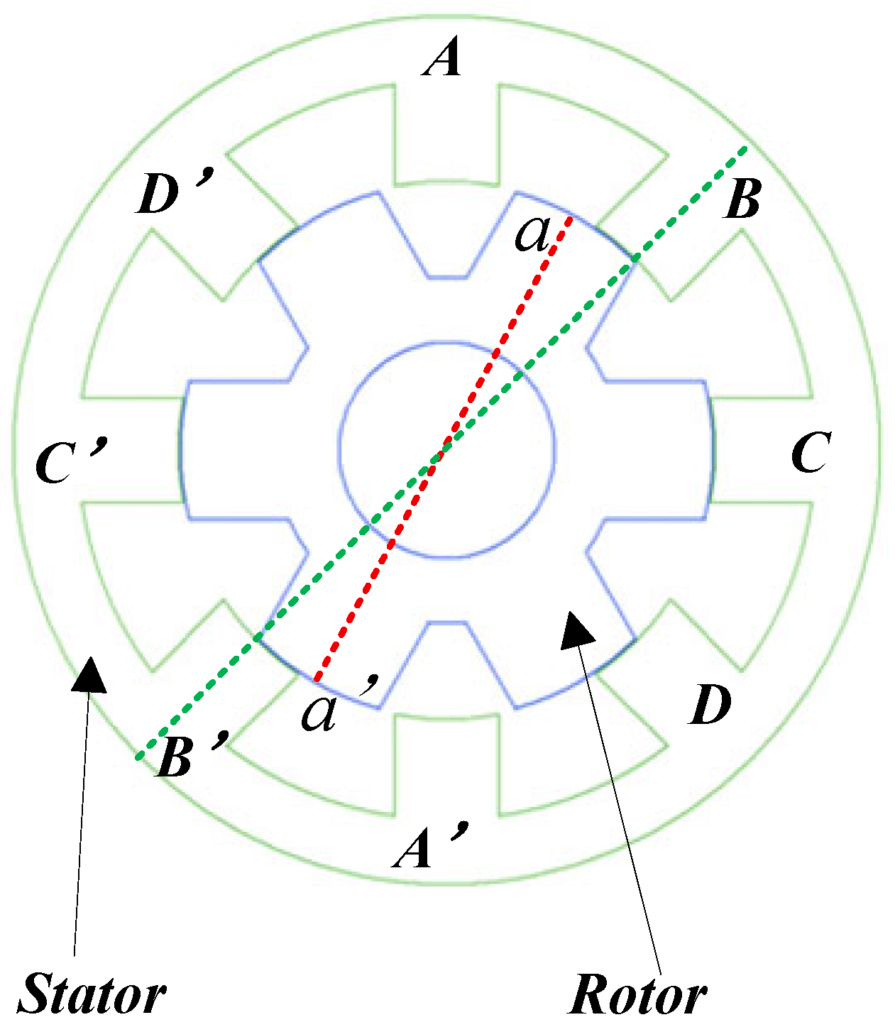
Figure 1 illustrates the structural configuration of an 8/6 pole, four-phase SRM. When phase B of the stator is energized, the resulting magnetic field drives the rotor to align its pole axis (a-a′) with the stator pole axis (B-B′), thereby maximizing the inductance of the B-phase winding. If this alignment is defined as the initial position, then energizing the A, B, C, D, and A-phase windings sequentially will cause the rotor to rotate continuously in the counterclockwise direction, following the reverse excitation sequence. Conversely, energizing the phases in the order A, D, C, B, and A will produce continuous clockwise rotation [
24].
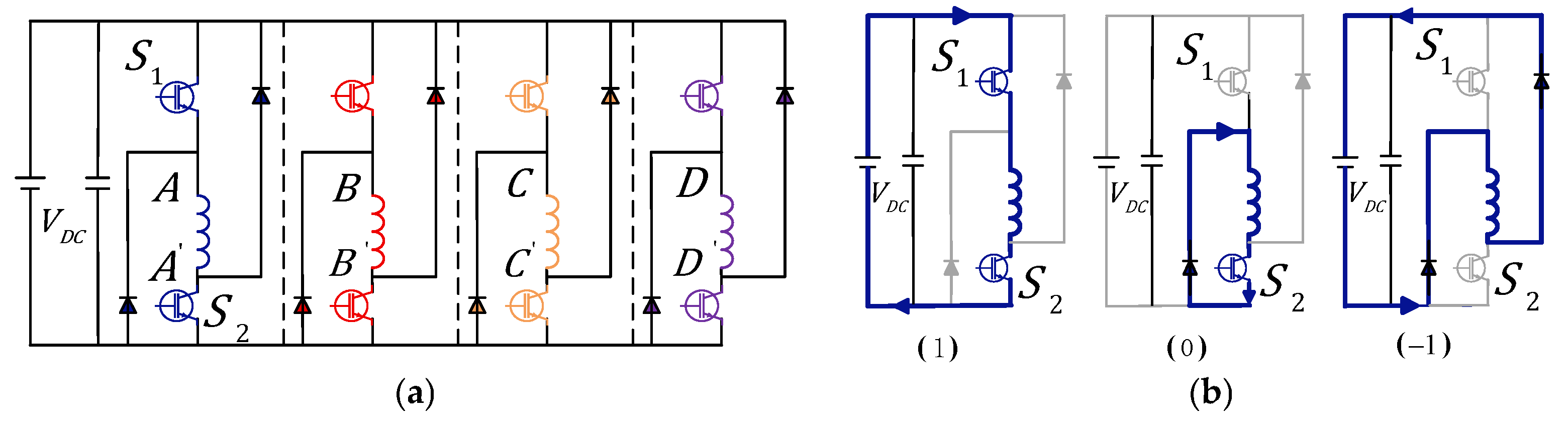
The 8/6 SRM is powered by a high-efficiency converter employing a four-phase asymmetric half-bridge converter (AHBC) topology (
Figure 2a). Each motor phase operates independently with unidirectional current flow. The converter provides three distinct switching states for each phase (
Figure 2b). When both the upper and lower power switches of a phase winding are turned on, the phase current rises rapidly under a positive voltage, corresponding to the magnetization state (Vdc = +1). When one switch is turned on and the other is turned off, the phase current decreases slowly under zero voltage, corresponding to the freewheeling state (Vdc = 0). When both switches are turned off, the phase current decreases rapidly under a reverse voltage, corresponding to the demagnetization state (Vdc = −1). T The blue lines in the figure indicate the corresponding current conduction paths within the power converter under each voltage level.
3. Design of Collaborative Control Strategy
To address the issue of torque ripple in SRMs, this study proposes a collaborative control strategy that integrates MPC with DITC. By combining the complementary strengths of both methods, the strategy enhances steady-state performance by achieving lower torque ripple and significantly improves the system’s ability to resist external disturbances. The following sections detail the design principles and coordination mechanisms underlying each component of the proposed control architecture.
3.1. TSF Selection
To reduce SRM phase-to-phase torque ripple, the TSF method distributes the torque of each phase based on the rotor position and a preset function. The sum of the torque distribution functions for all phases equals 1, satisfying Equation (8).
where
represents the number of phases of the SRM and
represents the TSF of the
k-th phase.
Various allocation strategies have been proposed for torque sharing in SRMs, among which the most commonly used torque distribution functions include linear, cosine, exponential, and quadratic forms. The reference torque for a single phase
derived from the selected distribution function, is defined by Equation (9):
To reduce implementation complexity and ensure compatibility with real-time control requirements, this study adopts the cosine-based TSF. This function distributes the
smoothly and symmetrically among all phases as a function of the
. Its mathematical formulation is given below:
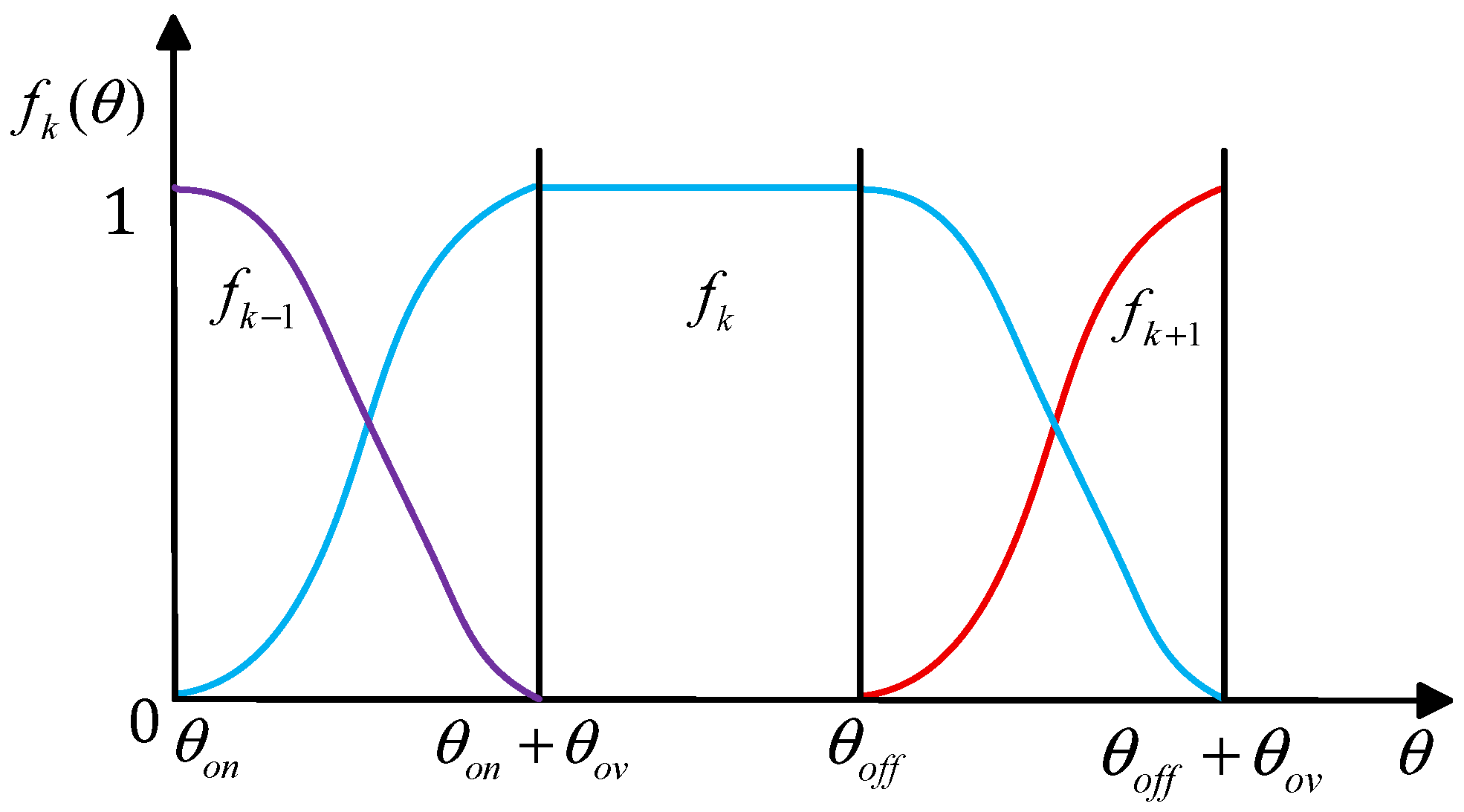
where
,
and
represent the turn-on angle, commutation overlap angle and turn-off angle, respectively.
Figure 3 illustrates the schematic representation of the cosine-based torque distribution function curve.
3.2. Improved MPC Design
The prediction of the
is conducted using a linear approximation method:
The flux linkage at the next time step is estimated using a linear approximation based on the present flux linkage and phase current:
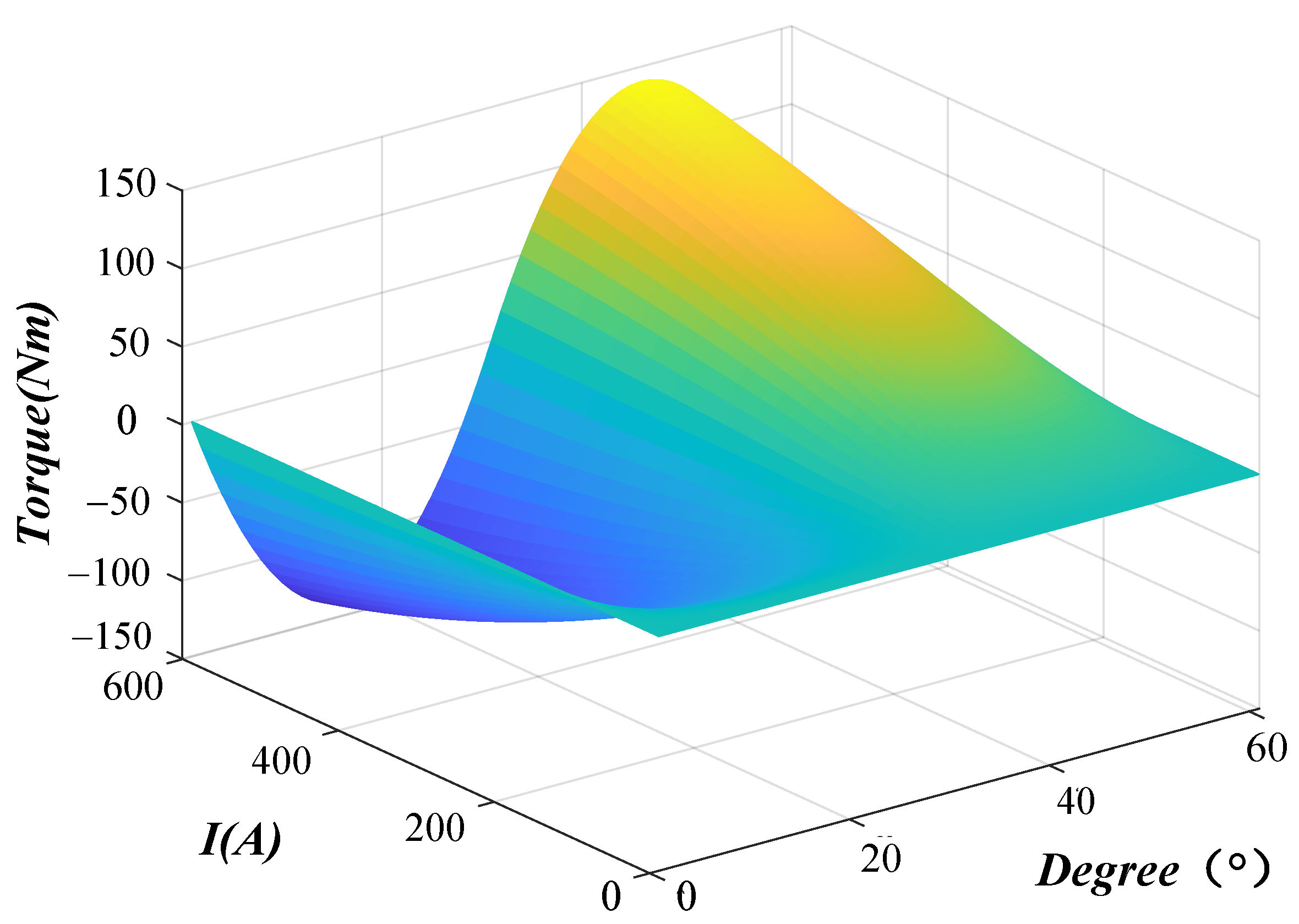
An SRM model was developed using Ansys/Maxwell 2026 R1, from which flux linkage and torque characteristic curves were extracted. The simulation covered a
range of 0°~60°, a current range of 0~500 A, with step sizes of 0.1° for angle and 1 A for current. These parameters were used to generate high-resolution flux linkage and torque data. A lookup table approach was then employed to map the predicted current and torque values, significantly reducing the computational burden of the MPC algorithm while enhancing prediction accuracy [
25]. The torque characteristics of the SRM are depicted in
Figure 4.
Once the predicted torque value
is obtained, cost functions for both torque and current can be formulated. The control objective is twofold: to suppress torque ripple and to maintain a low current level, thereby minimizing power converter losses. Accordingly, the composite cost function is defined as follows:
where
represents the cost function output; while
and
represent the weighting coefficients for torque and current, respectively.
Based on engineering optimization, the torque error and current terms in the cost function are normalized to balance their relative influence. Subsequent simulation-based tuning demonstrated that the system maintains robust performance when the weighting coefficients are set to and , therefore and were selected, respectively.
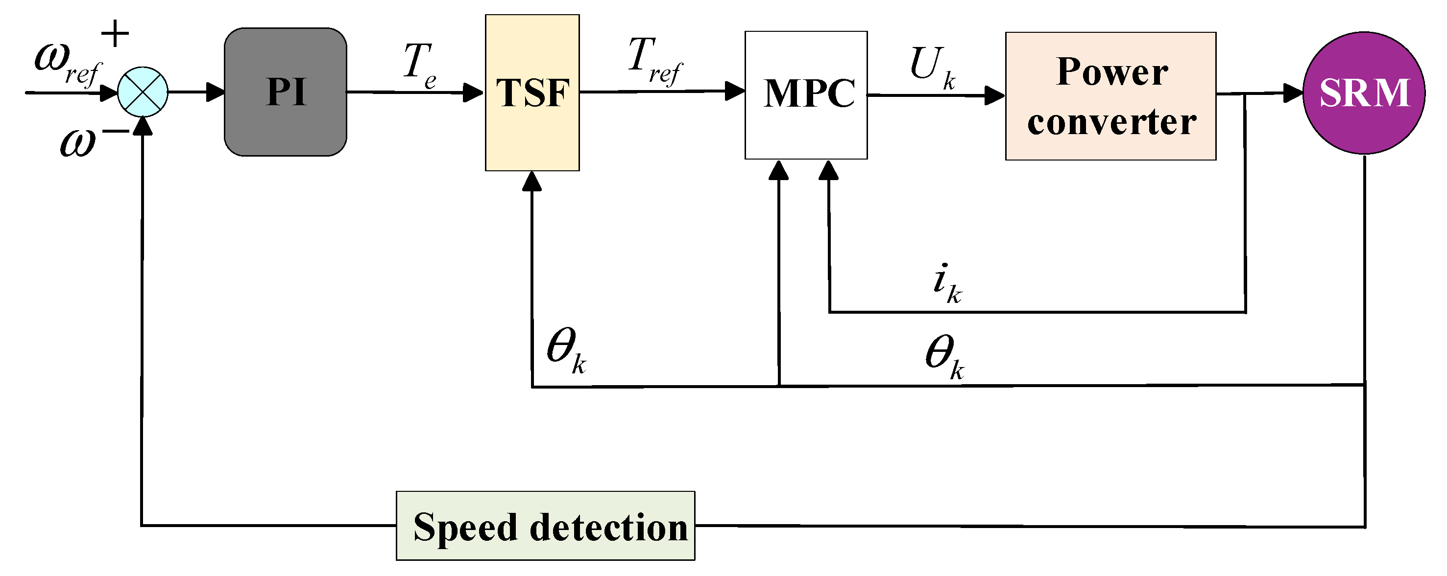
In conventional MPC, the
generated by the outer speed control loop is used as the input command. The corresponding control block diagram is presented in
Figure 5. This approach relies on real-time measurements of the motor’s phase current and rotor position, and employs a rolling optimization process based on a predefined prediction model to determine the optimal switching signals for the power converter, thereby regulating motor torque. While this method is widely adopted, it has inherent limitations. Specifically, the output switching signals are constrained by the direct current (DC) bus voltage and are discrete in nature, meaning they cannot be continuously adjusted in response to real-time system variations.
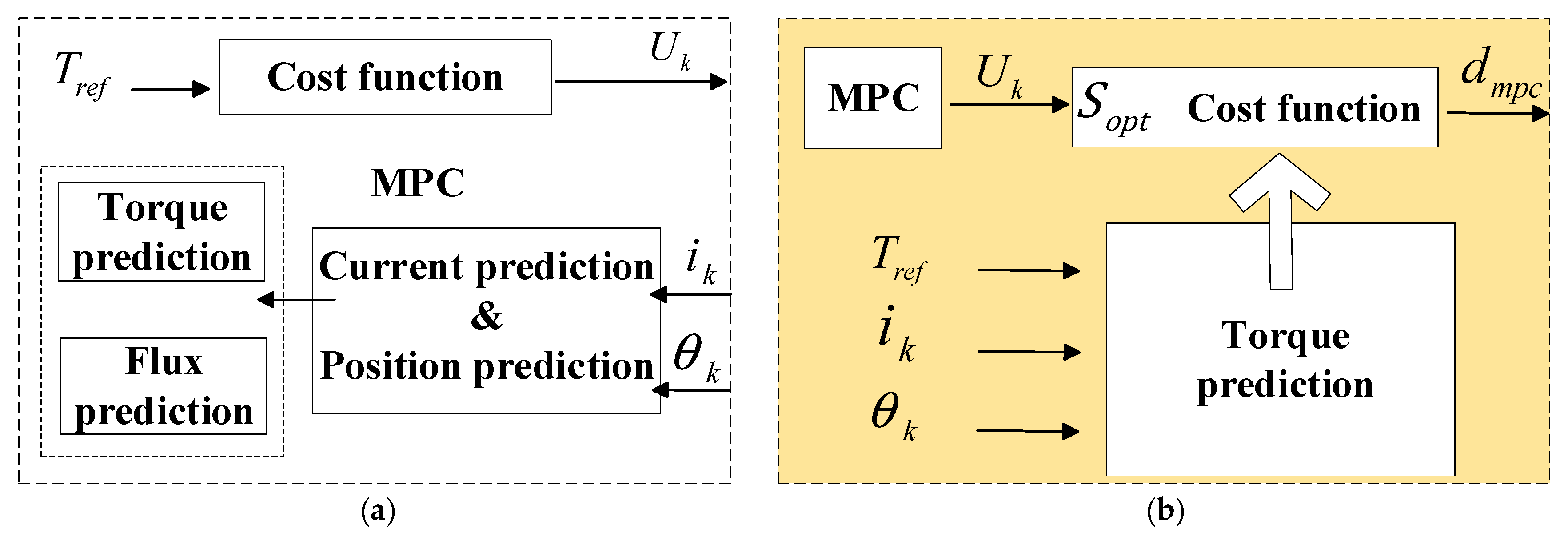
To overcome the limitations of conventional MPC, this study introduces a key enhancement to the controller design: Rather than generating discrete switching signals over the entire control cycle, the improved MPC outputs a continuous, optimized duty cycle signal. This modification enhances the resolution and flexibility of torque control. The control block diagram of the enhanced MPC scheme is illustrated in
Figure 6.
At the beginning of each sampling interval
, all feasible switching states
are exhaustively evaluated. For each candidate state, the predicted torque
at a future time step
is computed using the system’s predictive model. The cost function is then assessed for each case, and the switching state yielding the lowest cost is selected as the preliminary optimal state
.
Once the is determined, its corresponding optimal activation duration within the current control cycle is computed—this duration defines the optimal duty cycle . A quadratic optimization approach based on torque tracking is employed in this work to solve for the .
Within each , and the zero-voltage state are applied in a time-weighted combination to achieve the desired average torque. The duration of is , where is the duty cycle to be determined.
At this stage, the system’s average predicted torque
can be approximated as a weighted sum of the
corresponding to the two switching states:
where
represents the predicted torque when applying the
. To minimize the deviation between the average predicted torque and the
, a corresponding cost function is formulated.
By substituting Equation (15) into Equation (16) and differentiating the resulting expression with respect to
, the
can be derived analytically by setting the derivative equal to zero:
By limiting the amplitude of
, the following equation can be expressed:
This result represents the final output of the enhanced MPC controller.
3.3. DITC Design
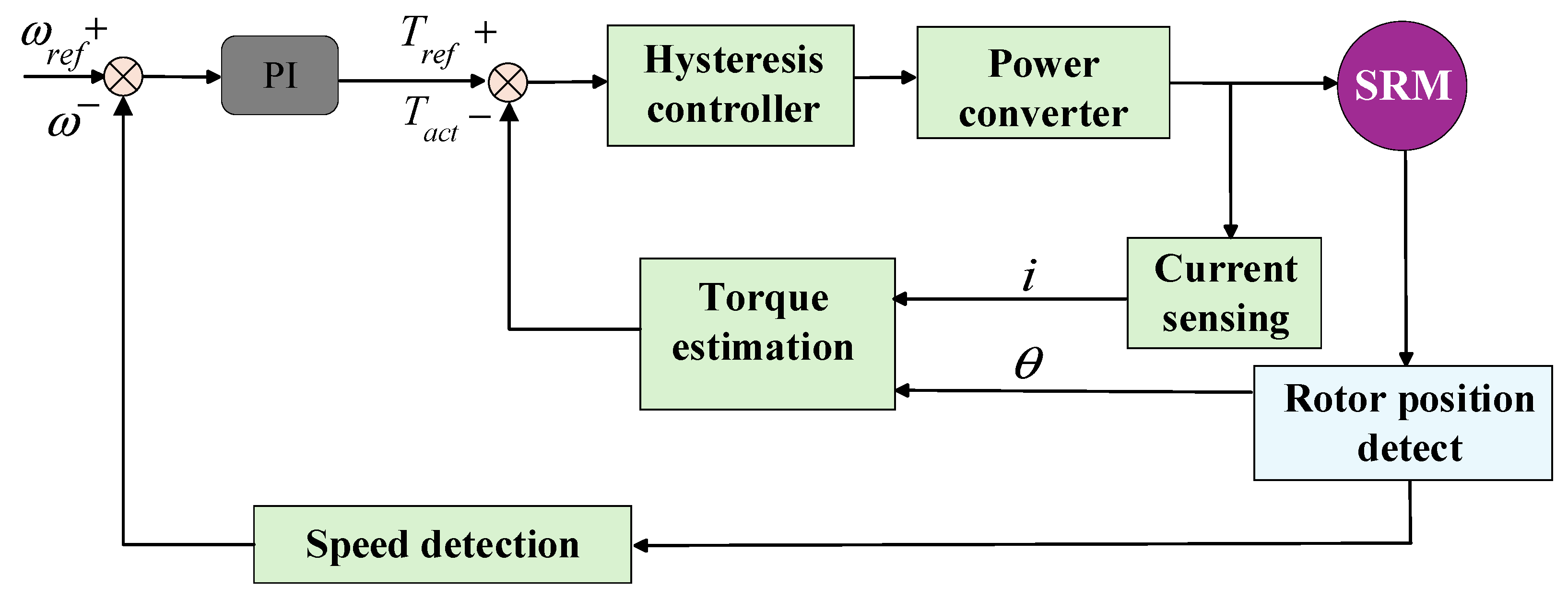
DITC is capable of detecting the instantaneous torque of the SRM at any given moment and directly using it as the control variable. Owing to its rapid response characteristics, DITC is particularly effective in suppressing high-frequency torque ripple. The conventional DITC structure is depicted in
Figure 7.
To overcome the delay and hysteresis issues associated with conventional MPC under disturbance conditions, this study incorporates DITC as a dedicated torque compensation module. This auxiliary control loop is triggered only in the presence of significant external disturbances, as determined by a torque error-based activation mechanism. During each control cycle, the system computes in real time the torque error
, defined as the difference between the
(via TSF) and the actual torque
, estimated through a torque observer.
- (1)
Threshold selection: To maintain control system stability, conventional DITC typically employs a threshold in the range of 5~10% of the rated torque. However, in this study, the threshold is increased to 20% of the rated torque to ensure that the compensation mechanism is activated only in response to significant torque deviations.
- (2)
MPC lag detection: When the,
exceeds the predefined threshold
, it is interpreted as an indication of delayed response in the MPC loop. Under this condition, the DITC module is immediately triggered to compensate for the lag.
- (3)
Returning to MPC: Following DITC activation, the system consults a pre-optimized offline switching table based on the current and directly applies the corresponding optimal voltage vector to the power converter, thereby enabling immediate suppression of torque ripple. To ensure a smooth transition between dynamic and steady-state modes, a hysteresis-based decision logic is incorporated: if the
remains below the lower threshold
for 5 consecutive control cycles, the system automatically switches back to MPC operation.
This hybrid control scheme ensures that DITC is engaged only when necessary, effectively leveraging its fast dynamic response to handle sudden disturbances without compromising steady-state performance.
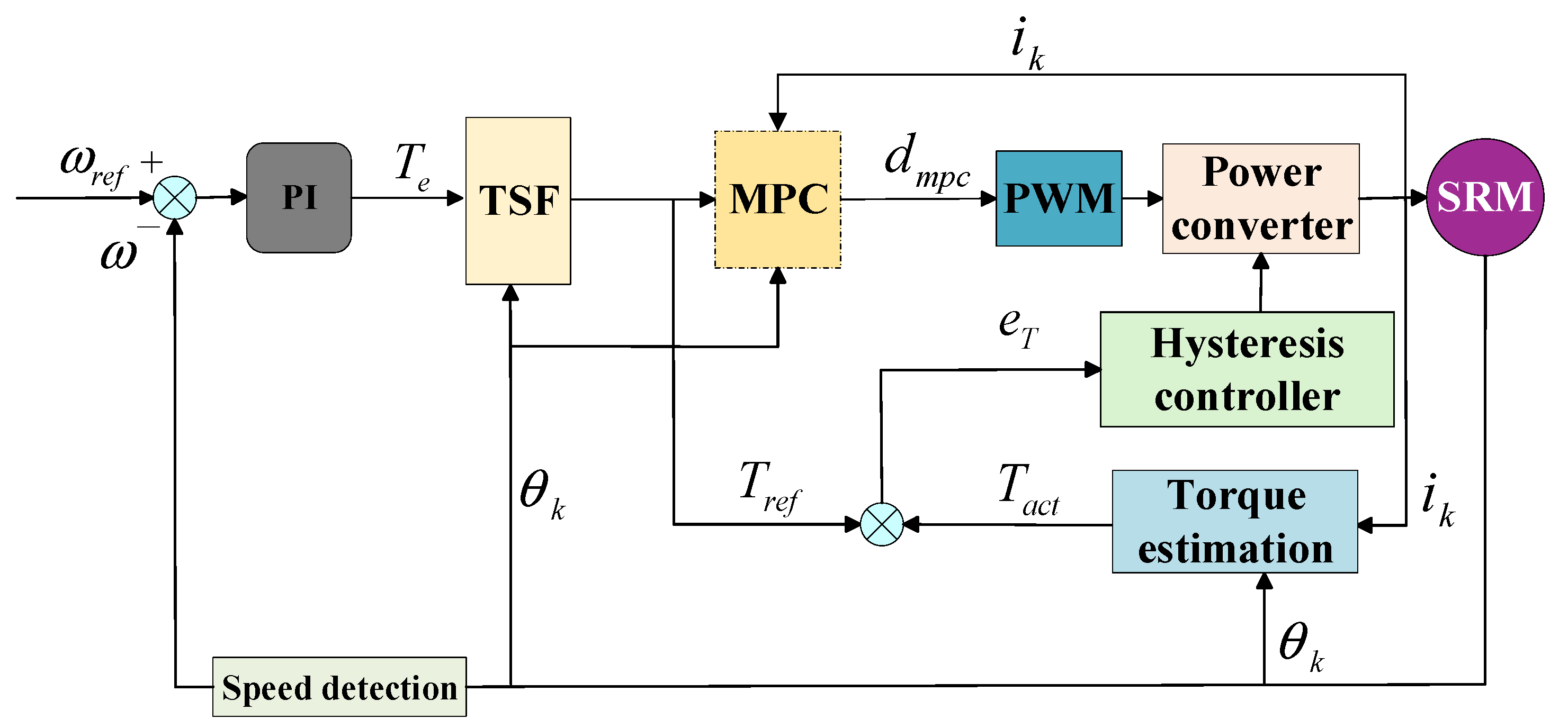
This paper proposes a collaborative control strategy that integrates MPC with DITC. The overall control architecture is illustrated in
Figure 8 and consists of the following operational modes:
- (1)
Steady-state operation: Under steady-state conditions, the motor’s phase parameters exhibit minimal variation. MPC utilizes the , generated by the TSF, as its input command. By solving for the
in real time, the controller achieves low torque ripple and stable system performance
- (2)
Disturbance-state operation: To compensate for the delayed dynamic response of MPC during transient disturbances, DITC functions as a fast-acting torque compensation loop. The , estimated via a torque observer, is compared against the TSF-provided , producing . This error is processed by the hysteresis controller to determine whether DITC activation is required. If the exceeds the , the DITC module is triggered, and compensation torque is immediately injected to mitigate the disturbance.
- (3)
Disturbance suppression and mode transition: Once the drops below the hysteresis threshold
and remains within this bound for a defined number of control cycles, the system automatically transitions back to MPC-dominant steady-state control. This ensures a smooth balance between dynamic responsiveness and steady-state stability, thereby enhancing the overall anti-disturbance capability of the control system.
4. Results
The SRM model was developed using a lookup table-based approach. Flux linkage and torque data were extracted from simulations conducted with the RMxprt and Maxwell 2D modules in the Ansys Electronics suite. These datasets were subsequently imported into the 2D Lookup Table module to establish the SRM’s nonlinear magnetic model. Furthermore, the torque data were utilized to compute the motor’s actual output torque. This was achieved by referencing the torque characteristic map, which correlates the operating current and rotor position angle. Through this method, the instantaneous torque output of the SRM can be accurately determined under varying operating conditions. The key structural parameters of the SRM are summarized in
Table 1 [
26].
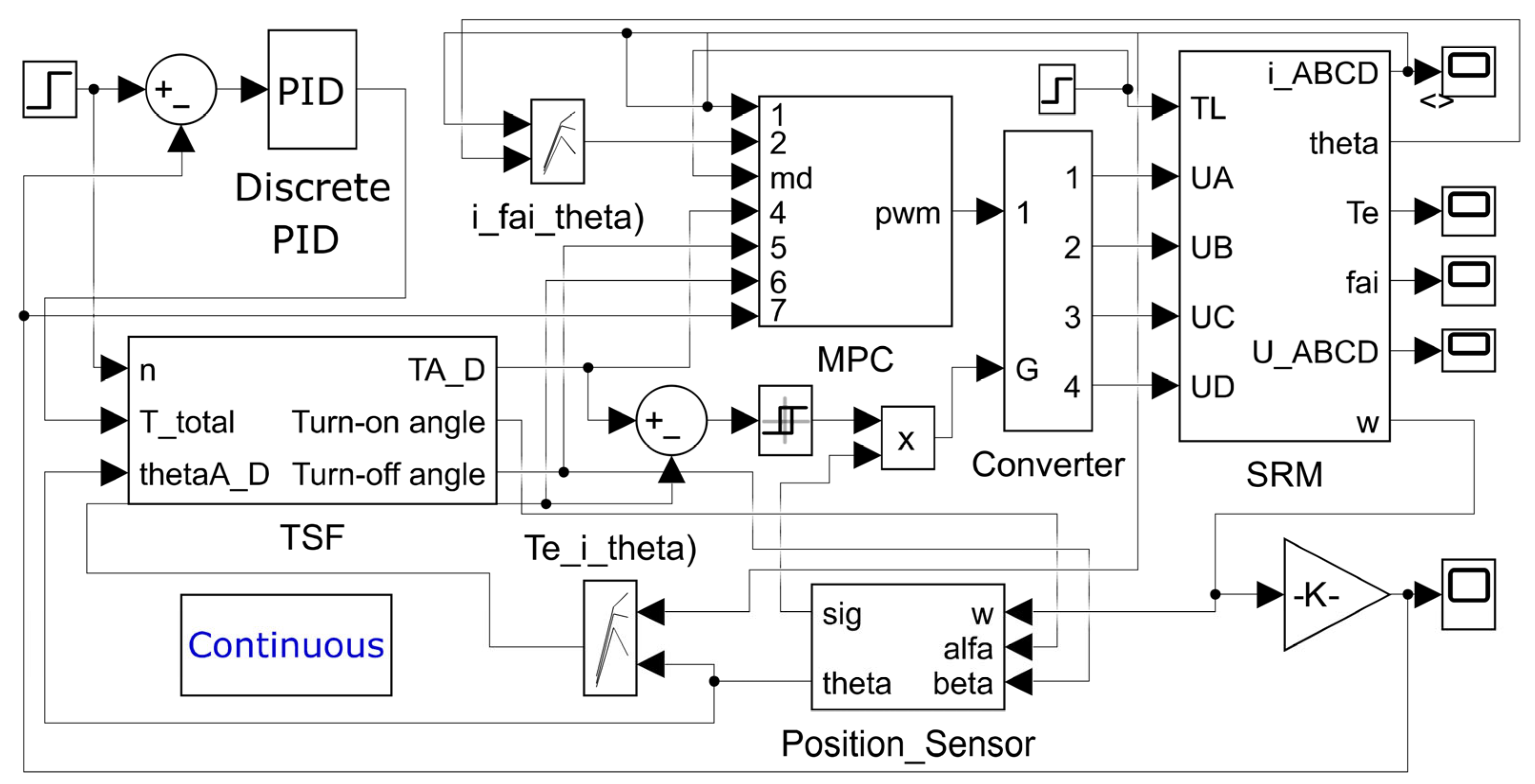
A simulation model of the SRM cooperative control system was developed in MATLAB/Simulink R2023b to validate the effectiveness of the proposed control strategy.
Figure 9 shows the top-level block diagram of the MATLAB/Simulink simulation system used in this study. The collaborative MPC-DITC scheme was benchmarked against the conventional MPC approach under identical operating conditions. The proposed simulation parameters are outlined in
Table 2. The torque ripple rate for the SRM is calculated using Equation (20) [
27].
where
represents the maximum torque;
represents the minimum torque; and
represents the average torque.
To quantitatively demonstrate the superiority of the proposed control strategy in suppressing torque ripple compared to the conventional MPC approach, the relative reduction rate of torque ripple is adopted as the evaluation metric. The corresponding formula is given by:
where
represents the torque ripple rate under the conventional control strategy and
represents the torque ripple rate under the improved control strategy.
To ensure a fair and consistent comparison, all control strategies were evaluated under identical simulation platforms and constraints. The DC bus voltage was fixed at 300 V, and the current limits, switching frequencies, and motor models were kept consistent across all tests. The TSF acted as a unified reference generator, supplying identical instantaneous torque commands to each control scheme. All MPC implementations adopted the same prediction horizon, control interval, and discretization model. The sampling period for the discrete-time control system was set to . The conventional MPC utilized discrete switching states as output, whereas the enhanced MPC produced a fixed-frequency duty cycle. Performance metrics were collected under identical dynamic testing conditions to ensure objective evaluation.
4.1. Operating Condition 1
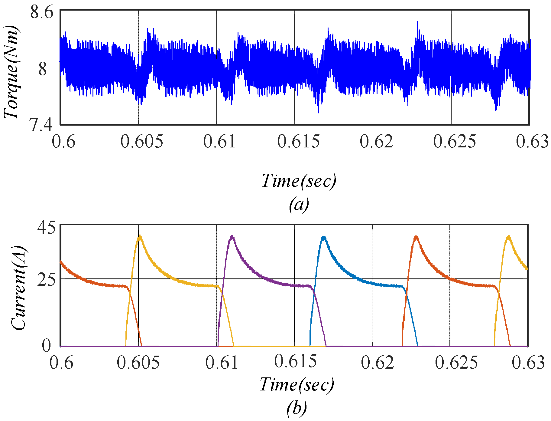
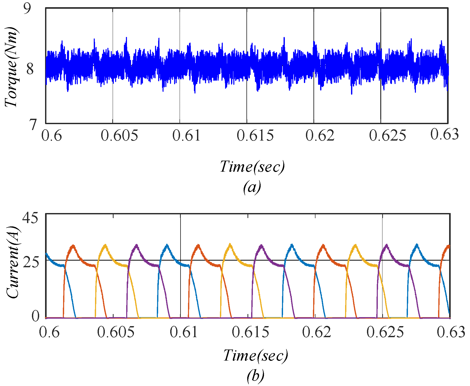
Low-Speed Operation: The motor was operated at a load torque of 8 Nm and a speed of 400 r/min. Two control strategies—conventional MPC and the proposed MPC-DITC collaborative control—were applied to the SRM system for performance evaluation. The steady-state torque and phase current waveforms are depicted in
Figure 10 and
Figure 11, respectively. Under these conditions, the torque ripple rates for the conventional MPC and the proposed strategy were 11.8% and 9.5%, respectively, while the corresponding peak phase currents were 41.29 A and 33.85 A.
These results indicate that the proposed collaborative control strategy reduces torque ripple and peak current by 19.4% and 18.02%, respectively, compared to the conventional MPC.
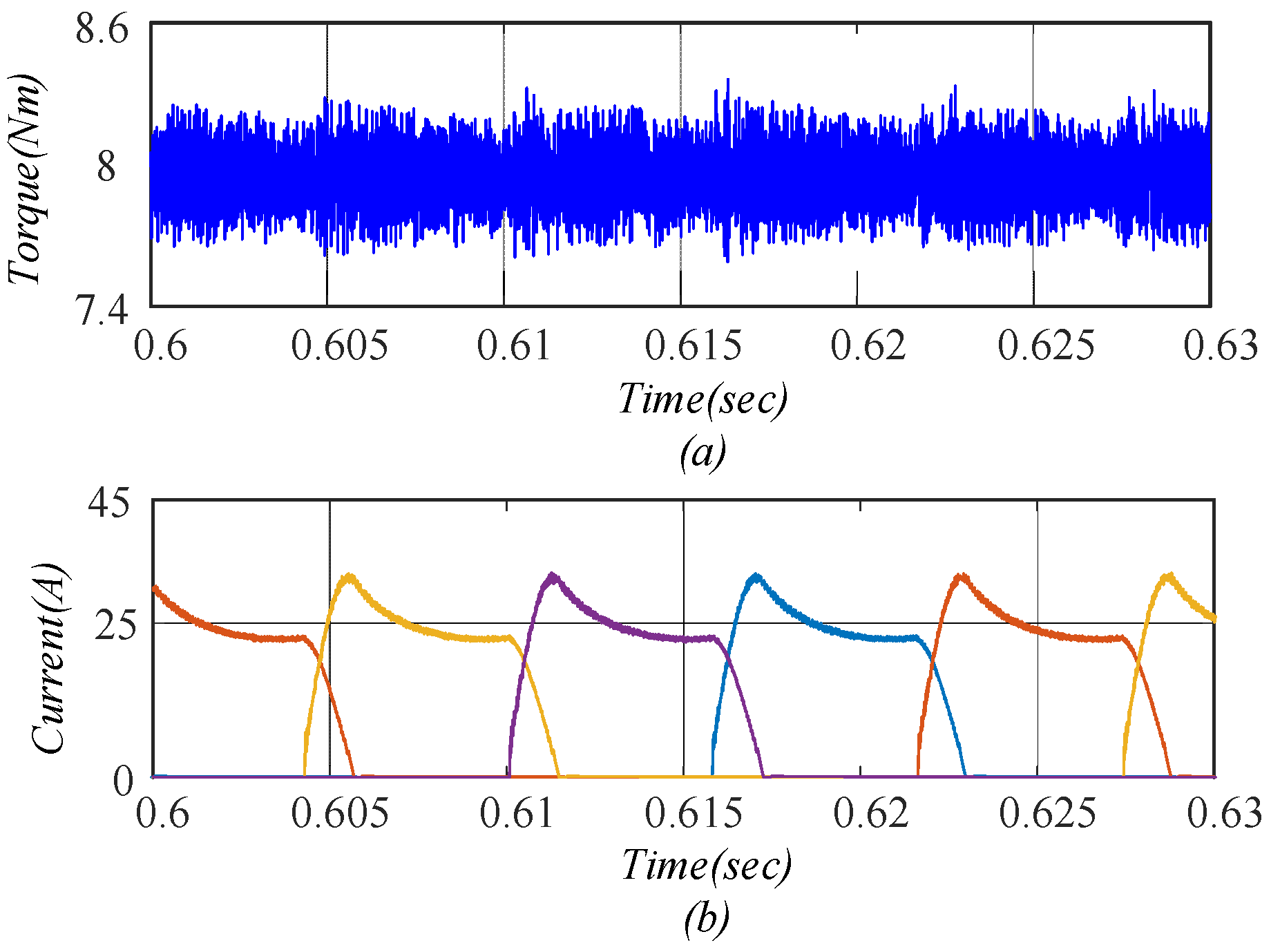
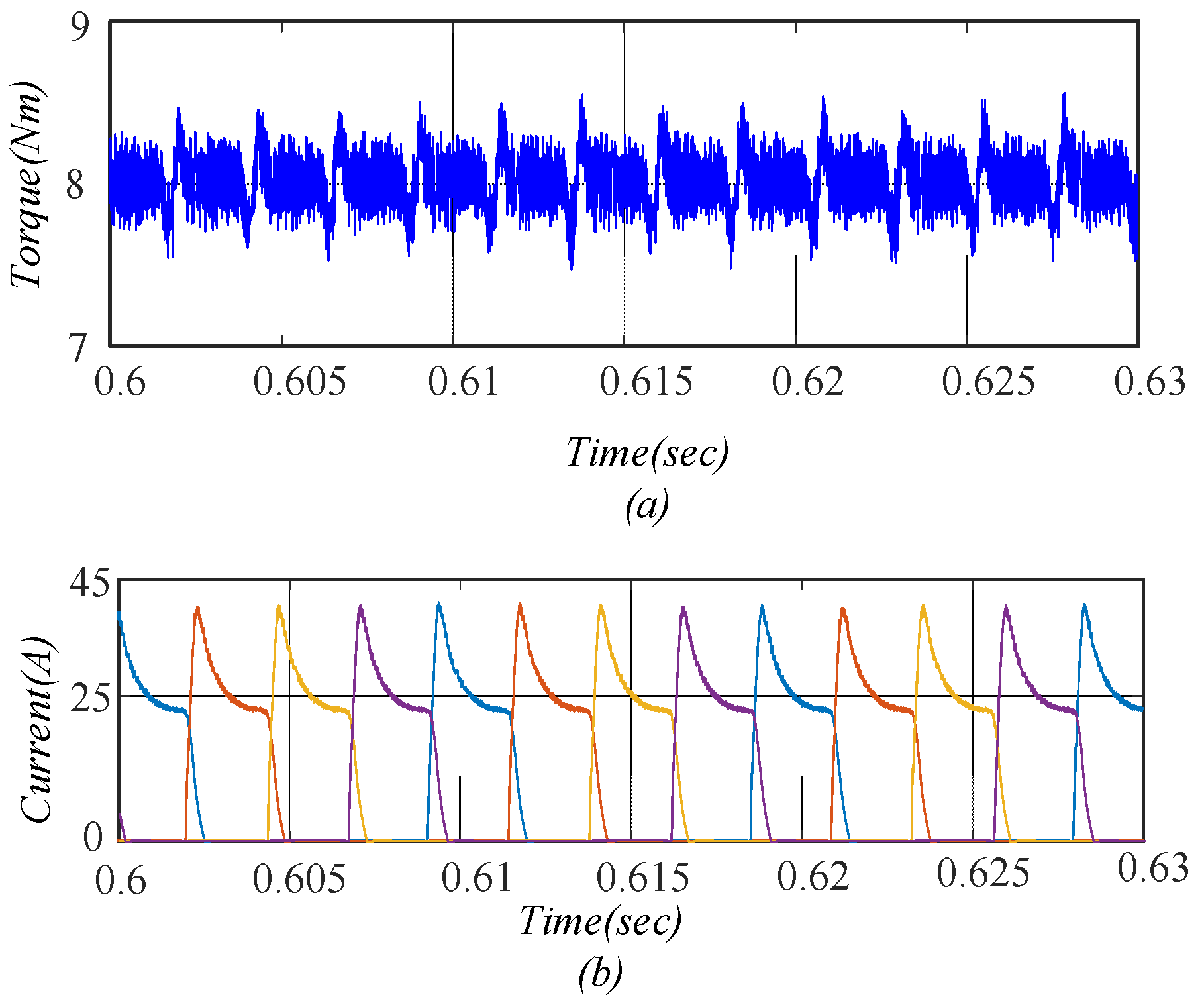
High-Speed Operation: The motor was operated under a load torque of 8 Nm and a speed of 1000 r/min. Both the conventional MPC and the proposed MPC-DITC collaborative control strategy were applied to the SRM system for performance comparison. The resulting steady-state torque and phase current waveforms are presented in
Figure 12 and
Figure 13, respectively. Under this condition, the torque ripple rates for the conventional MPC and the proposed strategy were 14.05% and 12.18%, respectively. The corresponding peak phase currents were 41.05 A and 32.10 A.
In summary, the proposed control strategy achieved a 13.31% reduction in torque ripple and a 21.8% reduction in peak current compared to the conventional MPC. These improvements confirm the effectiveness of the collaborative control approach in enhancing high-speed torque ripple suppression while significantly reducing peak current levels, thereby lowering the power converter’s thermal and conduction losses.
According to the simulation results under constant operating conditions, the proposed collaborative control strategy outperforms the conventional MPC by reducing both torque ripple and peak current during steady-state operation at both low and high speeds. These improvements contribute to enhanced steady-state performance and overall system efficiency.
4.2. Operating Condition 2
- (a)
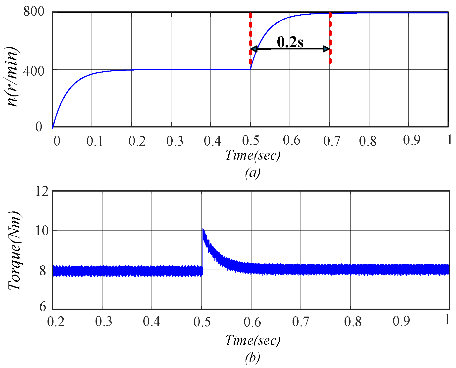
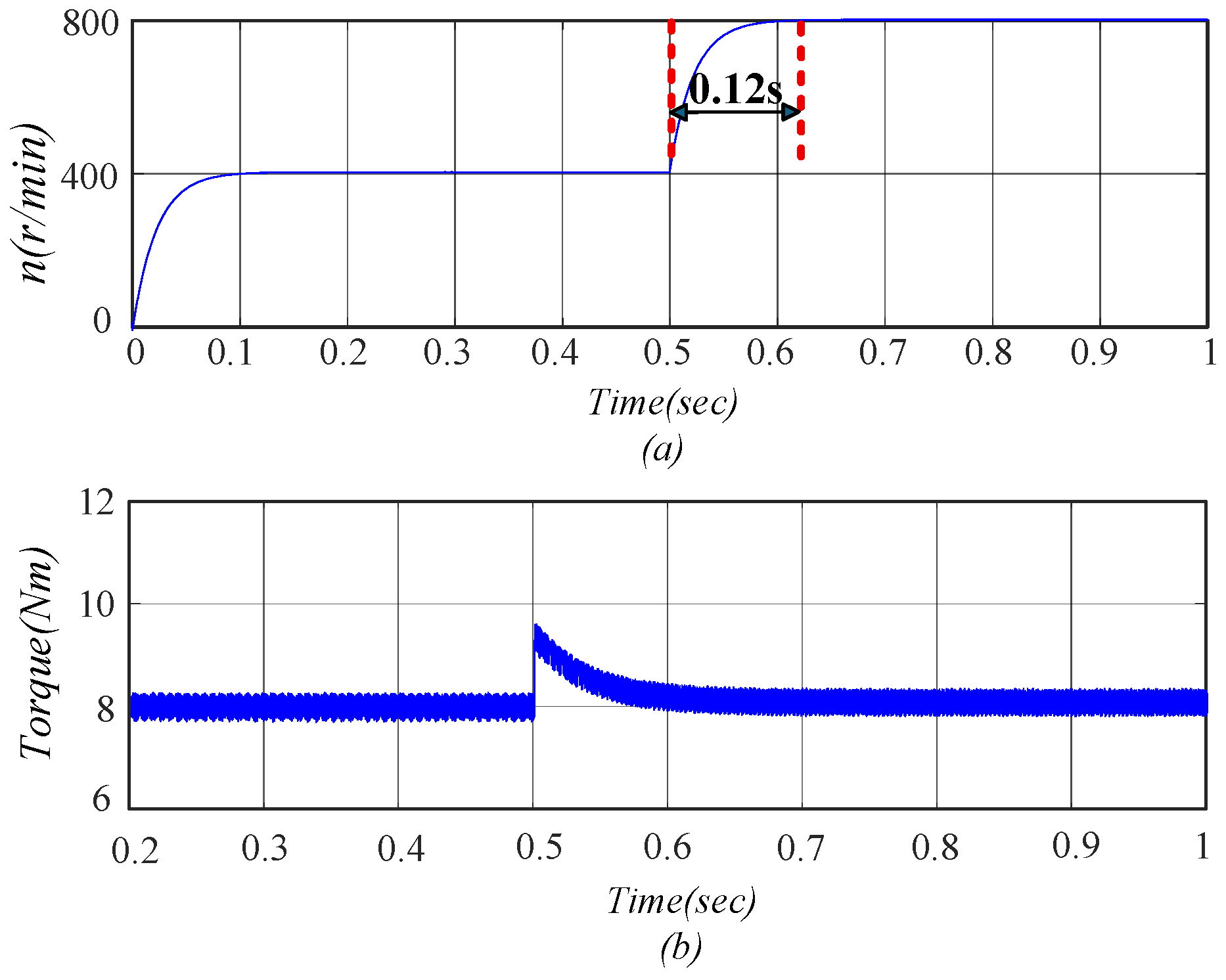
Acceleration: To evaluate the system’s dynamic response, the motor load torque was set to 8 Nm and the initial speed to 400 r/min. At t = 0.5 s, the speed command was abruptly increased to 800 r/min. Two control strategies—conventional MPC and the proposed MPC-DITC collaborative strategy—were applied to the SRM system. The corresponding motor speed and torque waveforms are illustrated in
Figure 14 and
Figure 15.
The simulation results indicate that both strategies successfully track the speed command during the transient. However, the acceleration time using the conventional MPC was 0.20 s, whereas the proposed strategy reduced it to 0.12 s. After the system stabilized, the torque ripple rates were 7.89% and 6.69% for the conventional and proposed strategies, respectively.
In summary, the proposed collaborative control strategy reduced the stabilization time following a sudden speed increase by 40%, and lowered the steady-state torque ripple by 15.21% compared to the conventional MPC. These results confirm the superior dynamic response and enhanced disturbance rejection capability of the MPC-DITC collaborative control scheme for SRM systems under rapid speed transitions.
- (b)
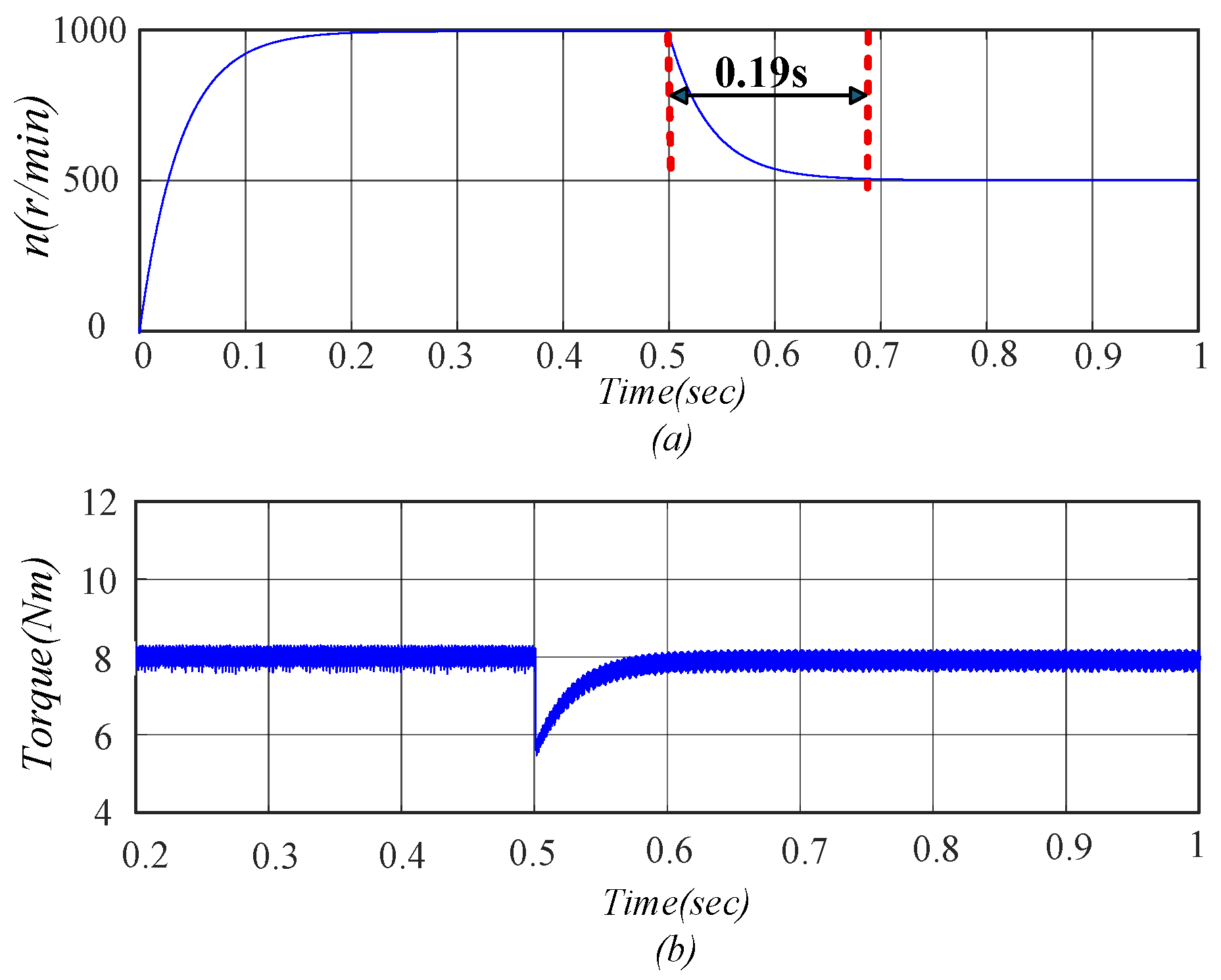
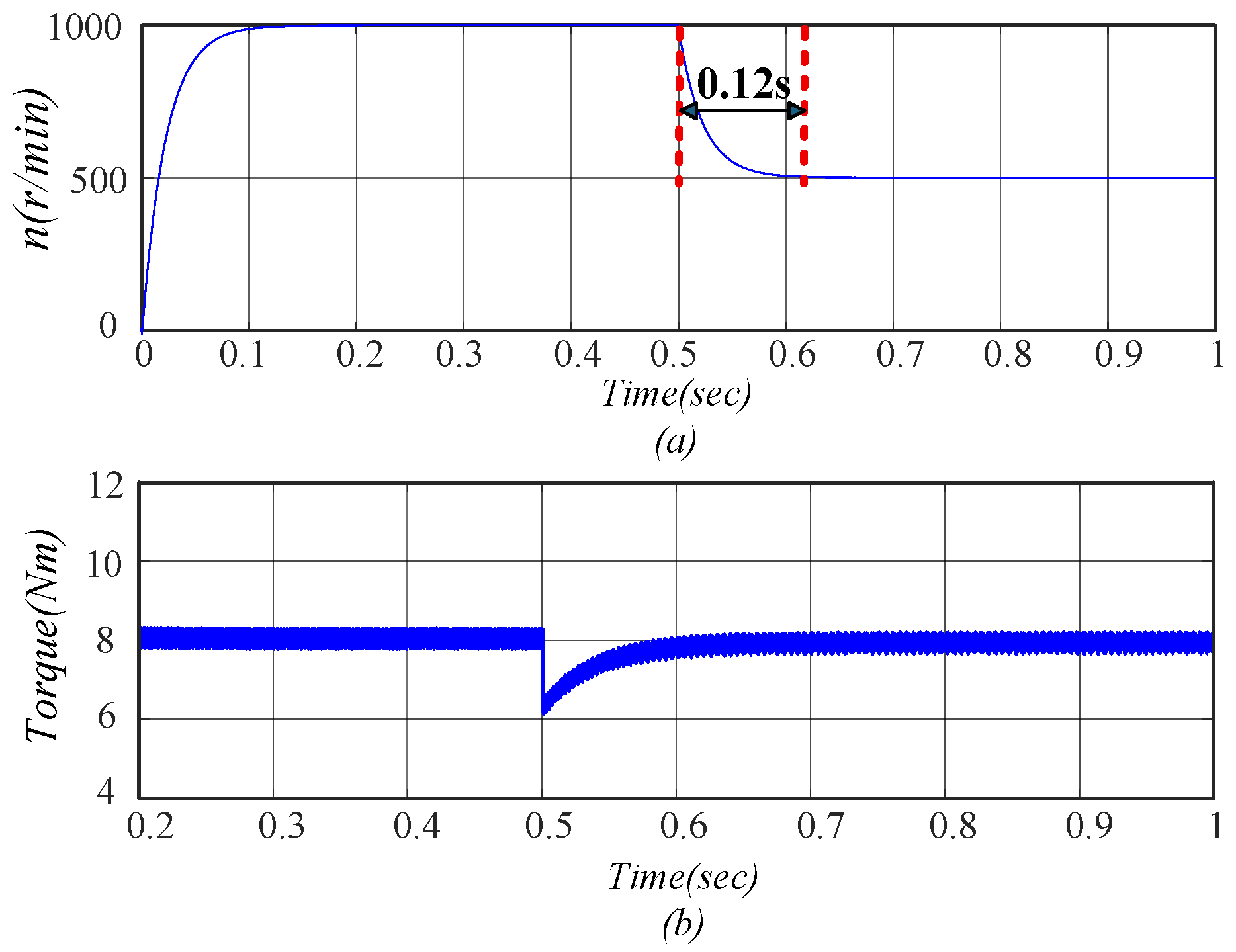
Deceleration: To further evaluate the dynamic response of the system, the motor was subjected to a sudden deceleration scenario. The load torque was maintained at 8 Nm, with the initial speed set to 1000 r/min. At t = 0.5 s, the speed command was abruptly reduced to 500 r/min. Both the conventional MPC and the proposed MPC-DITC collaborative control strategies were applied to the SRM system. The resulting speed and torque responses are depicted in
Figure 16 and
Figure 17.
Simulation results demonstrate that both strategies are capable of tracking the speed command during the transient. However, the time required for the system to settle was 0.19 s for the conventional MPC and 0.12 s for the proposed strategy. After reaching steady state, the torque ripple rates were 7.07% and 6.96%, respectively.
Collectively, the proposed control strategy reduced the stabilization time by 36.84% and the torque ripple by 1.56% compared with the conventional MPC. These findings highlight the strategy’s enhanced ability to restore the SRM system to steady operation more rapidly following sudden speed decreases, thereby improving its overall disturbance rejection performance.
- (c)
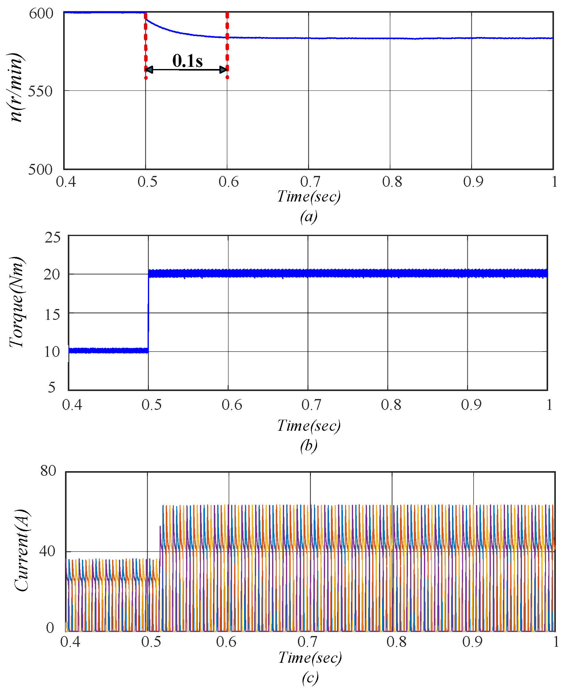
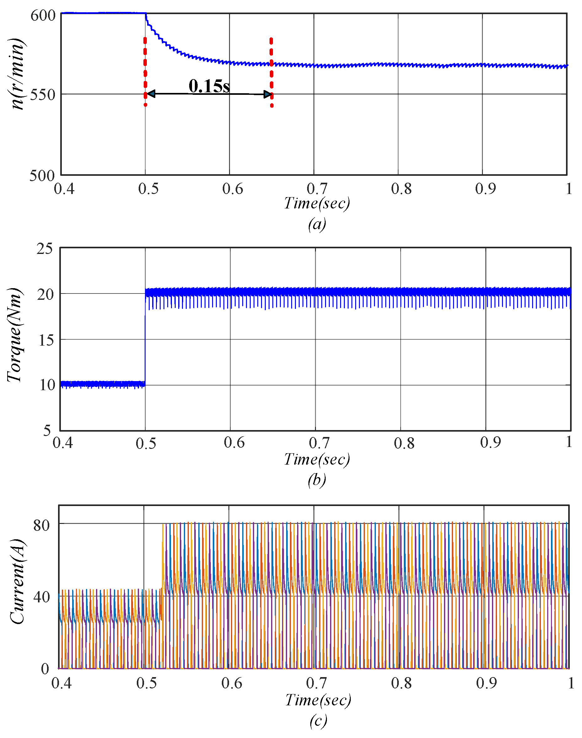
Sudden load increase: To evaluate the system’s performance under sudden load disturbances, the motor speed was set to 600 r/min and the initial load torque to 10 Nm. At t = 0.5 s, the load torque was abruptly increased to 20 Nm. Both the conventional MPC and the proposed MPC-DITC collaborative control strategies were applied to the SRM system. The simulation results of motor speed, electromagnetic torque, and phase current are presented in
Figure 18 and
Figure 19.
The simulation results show that a sudden increase in load torque causes a temporary drop in motor speed. The recovery times for the conventional MPC and the proposed strategy were 0.15 s and 0.10 s, respectively. After reaching steady state, the torque ripple rates were 11.58% and 5.91%, while the corresponding peak phase currents were 80.79 A and 63.45 A.
Overall, compared to the conventional MPC, the proposed control strategy reduced the recovery time by 33.33%, the torque ripple by 48.96%, and the peak current by 21.46% following a load surge. These results demonstrate the superior dynamic compensation and current suppression capabilities of the MPC-DITC collaborative strategy, significantly enhancing the SRM system’s stability and anti-disturbance performance under sudden load variations.
- (d)
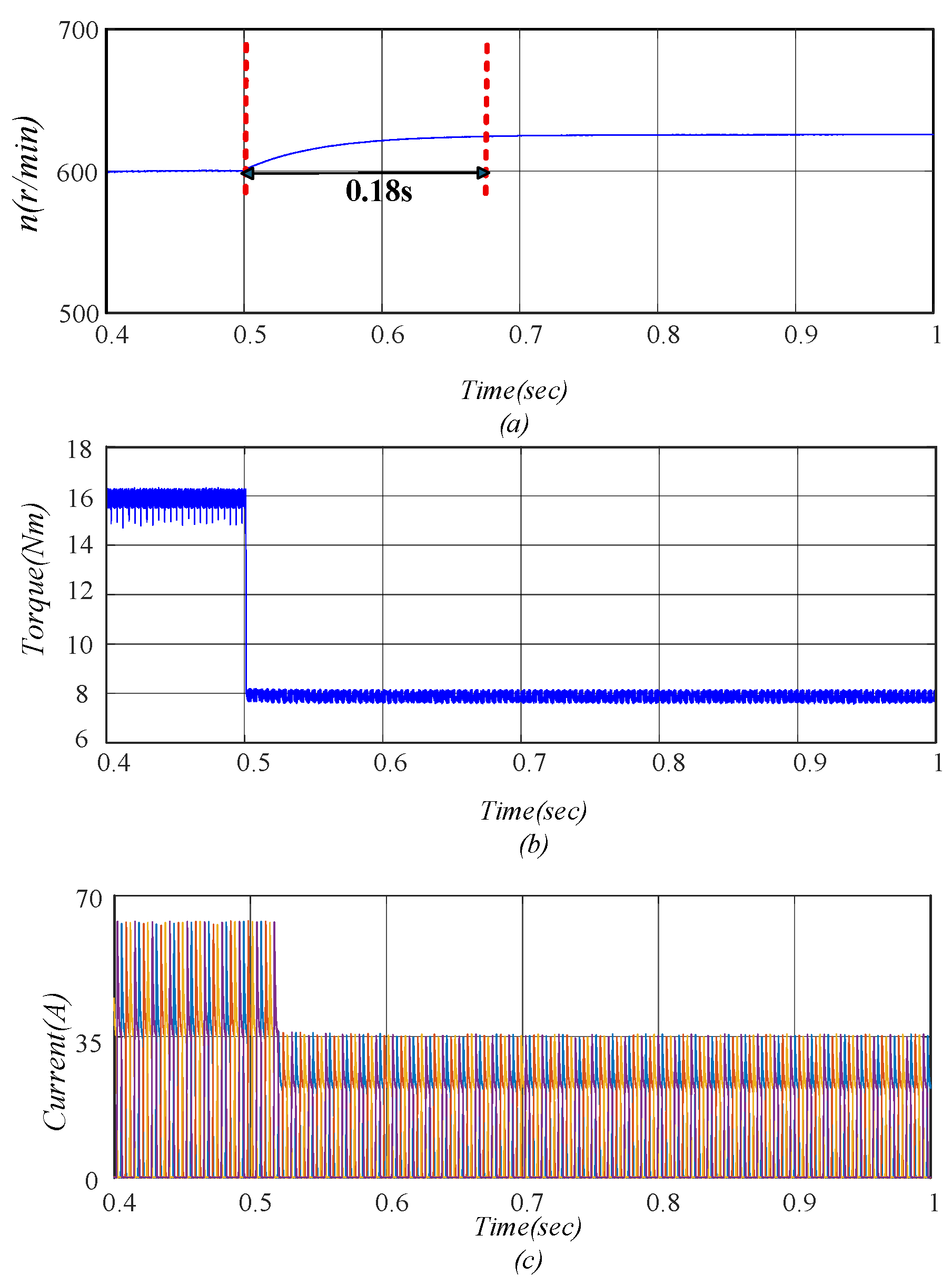
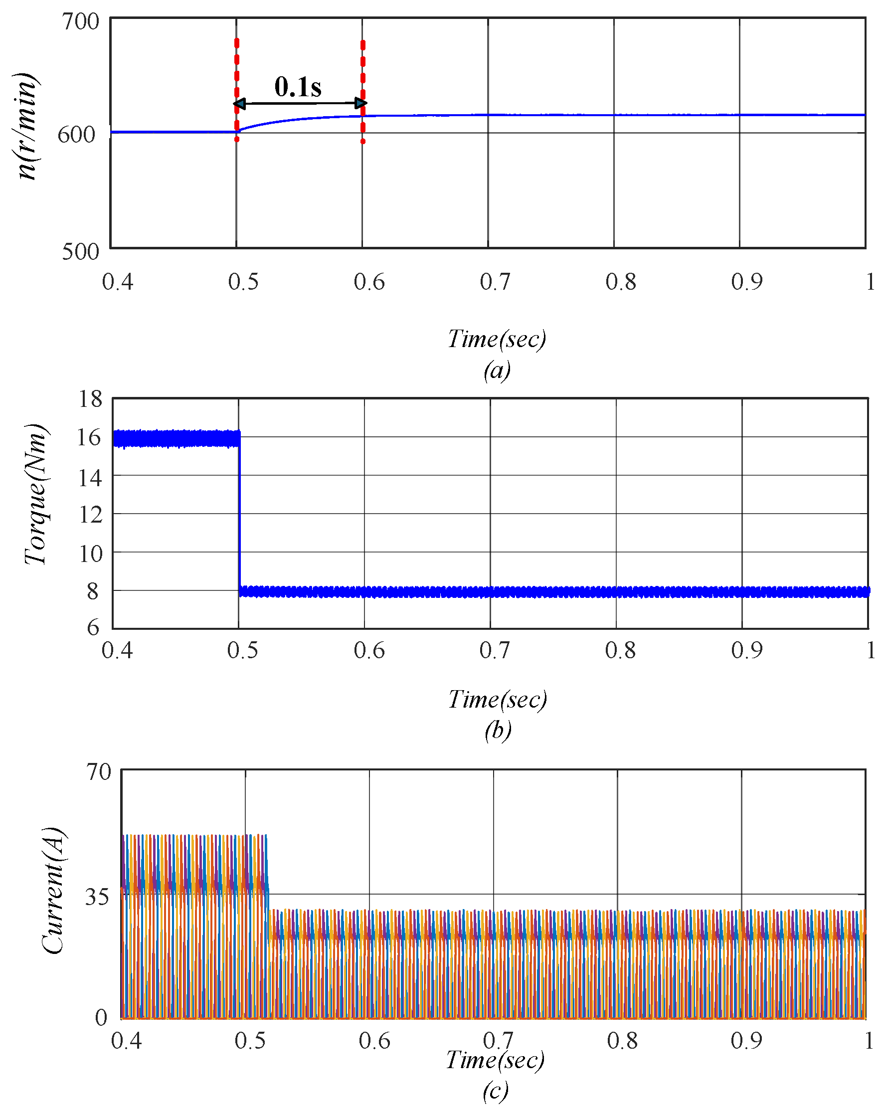
Sudden load decrease: To assess the system’s response to a sudden decrease in load torque, the motor was operated at a constant speed of 600 r/min with an initial load of 16 Nm. At t = 0.5 s, the load torque was abruptly reduced to 8 Nm. Both the conventional MPC and the proposed MPC-DITC collaborative control strategies were applied to the SRM system. The resulting speed, torque, and current responses are illustrated in
Figure 20 and
Figure 21.
The simulation results show that the sudden drop in load torque leads to a transient increase in motor speed. The recovery time to reach steady state was 0.18 s for the conventional MPC and 0.10 s for the proposed strategy. After stabilization, the torque ripple rates were 7.79% and 6.67%, while the peak phase currents were 35.64 A and 30.59 A, respectively.
Accordingly, compared to the conventional MPC, the proposed control strategy reduced the recovery time by 44.44%, the torque ripple by 14.39%, and the peak current by 14.17% following a sudden load decrease. These results confirm the enhanced dynamic adaptability and improved anti-disturbance capability of the MPC-DITC collaborative strategy in mitigating torque fluctuations during load reductions.
The above simulation results demonstrate that the proposed MPC–DITC collaborative control strategy achieves better control performance than the conventional MPC strategy under both steady-state and transient operating conditions. Under steady-state conditions, the proposed method effectively improves torque quality while reducing current stress in the drive system. Under speed and load disturbances, it exhibits faster recovery and better transient response. These results confirm that the proposed strategy can enhance both steady-state performance and the disturbance rejection capability of the SRM drive system.
5. Conclusion and Suggestions
To suppress torque ripple and improve the disturbance rejection capability of SRM drives, this paper proposes a collaborative control strategy integrating TSF, MPC, and DITC. In the proposed framework, the TSF-generated reference torque is used as the command input of the MPC controller during steady-state operation, while DITC is introduced as a fast compensation loop under transient disturbances. Simulation results show that the proposed method achieves better overall performance than the conventional MPC strategy.
The main conclusion of this study is that the proposed collaborative control strategy provides an effective solution for improving the overall control performance of the SRM drive system. The comparative results confirm the effectiveness of integrating TSF, MPC, and DITC in enhancing torque control capability and transient disturbance response under different operating conditions.
In addition, the proposed method is implemented using finite-element data and lookup tables for flux linkage and torque estimation. Compared with conventional MPC models based on discretized electromagnetic equations, this approach is more suitable for describing the nonlinear electromagnetic characteristics of the SRM over a wide operating range, thereby improving prediction accuracy. However, it also requires increased offline data preparation effort and higher memory requirements. Furthermore, torque ripple under low-speed operating conditions remains relatively high because the conventional cosine-based TSF adopted in this study has not yet been further optimized. In addition, a comprehensive evaluation of efficiency and loss characteristics has not yet been conducted. Moreover, the present study is limited to simulation-based verification, and experimental validation has not yet been carried out.
Future work will focus on the following aspects. First, the TSF design will be further optimized to improve torque ripple suppression performance, especially under low-speed operating conditions. Second, a more comprehensive efficiency evaluation framework will be established to analyze copper loss, iron loss, and converter-related losses, so that the influence of the proposed strategy on overall drive efficiency can be systematically assessed. Third, experimental validation based on a physical prototype will be conducted to compare with the simulation results and further verify the practical feasibility and effectiveness of the proposed control strategy.