Article

Analytical Calculation and Verification of Radial Electromagnetic Force Under Multi-Type Air Gap Eccentricity of Hub Motor

1
School of Automobile and Transportation, Henan Polytechnic, Zhengzhou 450046, China
2
School of Mechatronics and Vehicle Engineering, Chongqing Jiaotong University, Nanan District, Chongqing 400074, China
*
Author to whom correspondence should be addressed.
World Electr. Veh. J. 2025, 16(8), 473; https://doi.org/10.3390/wevj16080473 (registering DOI)
Submission received: 17 June 2025 / Revised: 21 July 2025 / Accepted: 4 August 2025 / Published: 19 August 2025

Abstract

This paper presents a method for calculating radial forces in switched reluctance motors (SRMs) under radial and tilted air gap eccentricity states. Firstly, the Fourier series method is used to establish a nonlinear model of a switched reluctance motor, which calculates the air gap length at different positions around the motor circumference and applies the Radial Electromagnetic Force (REF) equation to compute the radial force values at various positions under the air gap eccentricity states. Secondly, the finite element method is employed to analyze the factors influencing radial forces in switched reluctance motors under air gap eccentricity states, considering different winding phases and structural parameters as influencing factors. Finally, a measurement platform for radial forces under multiple types of air gap eccentricity states is established to validate the effectiveness of the analytical results for radial forces under radial and tilted air gap eccentricity states.

1. Introduction

In response to the many challenges posed by increasing environmental pollution and the greenhouse effect, more environmentally friendly, energy-saving, and energy-efficient electric vehicles have become the main direction of future automobile development [1,2,3]. The use of hub motors in driving vehicles is known for their compact structure and highly integrated control system design, which enables independent control and rapid response of the vehicle’s drive wheels. By adjusting the driving torque and speed of the four wheels to complete the vehicle differential steering, steering in place, and other modes, hub motor drive technology is expected to become the mainstream direction in the future development of electric vehicles. The Switched Reluctance Motor, a type of motor without a permanent magnet, offers advantages such as low cost, simple control, and a reliable structure, making it well-suited to meet the power demands of wheel hub motor-driven vehicles [4,5,6]. However, the highly integrated structure of these motors can increase the vehicle’s non-sprung mass [7,8]. In external disturbances such as road excitations, emergency steering, and emergency braking, hub motors can exhibit various air gap eccentricities, affecting the vehicle’s smoothness and handling stability [9,10,11]. Air gap eccentricities can be classified into three types based on their circumferential distribution: circumferential, axial, and mixed eccentricities. Circumferential and axial eccentricities refer to non-uniform distributions of the air gap along the circumference and axis of the motor. In contrast, mixed eccentricity refers to non-uniformity in both directions [12,13]. Additionally, eccentricities can lead to an imbalance in radial forces, exacerbating motor vibrations. Therefore, it is vital to investigate the mechanisms of radial forces under eccentricity states. In the study of radial forces, a combination of theoretical derivation, finite element analysis, and experiments is often used to analyze the effects of eccentricities on radial forces [14,15]. The results indicate that radial air gap eccentricities increase radial and axial radial forces, while axial eccentricities increase axial radial forces but decrease radial forces [16]. Under axial air gap eccentricity, the change in radial force per unit area of the stator due to the tilt angle of the rotor pole is analyzed. As the tilt angle increases, the stress and maximum deformation of the motor increase at the minimum air gap position [17]. Furthermore, other relevant influencing factors affecting radial force variation under eccentricity states should also be considered. Factors such as stator materials, stator slot structure, and motor casing can impact radial force variation. Studies have shown that stator and rotor size tolerances and eccentricities can lead to changes in the radial electromagnetic force [18]. Adjustments in the magnetic pole segmentation method and stator pole arc coefficient can also result in significant changes in radial force values [19]. Accurate calculation results of radial forces are essential for revealing the factors affecting radial force variation. The radial forces under radial air gap eccentricity are calculated using the principle of virtual displacement and the Maxwell stress tensor method, with a comparison of the differences between the two calculation methods [20]. An analytical model that can intuitively consider the variation of radial force under stator tooth pole modulation is proposed, and its effectiveness is verified through finite element analysis and experiments [21]. The analytical calculation formula for the radial force during rotor eccentricity operation is derived from the Maxwell stress tensor method [22].
In conclusion, previous studies have mainly focused on radial air gap eccentricities in conventional motors. However, research on radial forces in switched reluctance motors under tilted air gap eccentricity states is still severely limited, especially regarding analytical calculation methods and SRM-specific influencing factors. Therefore, this paper proposes an analytical calculation method for radial forces in SRMs that considers multiple types of air gap eccentricity states. By analyzing the radial force calculation results under various eccentricity types based on SRM air gap profiles and eccentric inductance characteristics, this method provides insights specific to SRM operation. Finally, the accuracy of the proposed analytical calculation method is validated through the established radial force measurement platform, avoiding the extensive computation time required for finite element analysis.

2. Calculation of Multiple Eccentric Radial Force

To investigate the radial force characteristics of switched reluctance motors (SRMs) under air gap eccentricity, this study adopts a hybrid approach that combines finite element (FE) analysis with analytical modeling. The modeling process consists of two main stages:
First, FE simulations are conducted to obtain accurate inductance profiles of the motor under various eccentric conditions, capturing the nonlinear magnetic behavior and geometric complexities that are difficult to model analytically. These simulations focus on three critical rotor positions: aligned (pole-to-slot), unaligned (pole-to-pole), and mid-alignment (pole-to-half-slot).
Next, the discrete inductance data are fitted using a low-order Fourier series, yielding a continuous analytical expression for inductance over one electrical period. This fitted inductance model enables the derivation of nonlinear flux linkage, magnetic co-energy, and ultimately, electromagnetic torque and unbalanced radial forces.
This hybrid methodology preserves the accuracy of FE-based calculations while offering analytical flexibility to efficiently study the effects of various eccentricity types. The approach forms the foundation for the subsequent analysis of multiple types of air gap eccentricity scenarios.

2.1. Type of Air-Gap Eccentricities

External impacts such as assembly errors and road excitations can cause air gap eccentricities in hub-switched reluctance motors. Common types of air gap eccentricities include radial and tilted eccentricities, as shown in Figure 1 [23]. In the normal state, the air gaps and radial forces at both ends of the motor poles are the same, and the motor operates normally. Radial air gap eccentricity refers to a change in the radial air gap between the stator and rotor of the motor while the tilted air gap remains unchanged. This results in the air gaps at both ends of the motor poles no longer being the same, leading to a sharp increase or decrease in the radial forces at both ends due to the change in the air gap. This imbalance in radial forces further exacerbates vibration issues in the motor. Tilted air gap eccentricity refers to radial and tilted air gap changes, as shown in Figure 1c. The changes in the tilted air gaps at both ends of the motor are the same, increasing the radial forces at both ends of the motor poles. This imbalance in radial forces will cause the motor to generate a tilting moment, affecting the regular operation of the switched reluctance motor.

2.2. Nonlinear Model of Switched Reluctance Motor

The structure of the outer rotor 8/6-pole switched reluctance motor selected in this study is shown in Figure 2. Choosing an outer rotor structure eliminates the need for a reducer, saves space in the hub motor drive system, and enables direct drive to the wheels, thus improving energy transmission efficiency. The motor consists of six rotor poles, eight stator poles, one stator support shaft, and a four-phase winding. The energization sequence of the winding phases determines the direction of motor rotation. For clockwise rotation, the energization sequence of the winding phases is A, B, C, D. For counterclockwise rotation, the sequence is A, D, C, B. Additionally, the structural parameters of the switched reluctance motor are shown in Table 1.
To characterize the nonlinear behavior of the motor, especially under eccentric conditions, this study focuses on modeling the phase inductance as a function of rotor position and current. Based on the FE-derived inductance data, a Fourier series is used to fit the data accurately, facilitating subsequent analytical force derivation. In the modeling, the initial angle is defined such that the stator pole aligns with the center of the rotor slot (the pole-to-slot position). After a rotation of half a rotor pole pitch (τr/2 = π/N, where Nr is the number of rotor poles), the stator and rotor poles are aligned (pole-to-pole position). The fitted inductance L (θ,i) is then expressed as [24]:
L θ , i = L 0 i + L 1 i cos N r θ + φ 1 +      n = 2 , 3 , L n i cos n N r θ + φ n      = n = 0 L n i cos n N r θ + φ n
In the equation, φn = nπ represents the phase angle of the nth harmonic component, θ is the rotor position angle, i is the phase current of the winding, and Ln is the coefficient of the Fourier series, derived from the inductance at each particular position of the winding phase [25]. The inductance data for key specific positions, including the pole-to-pole inductance (La), pole-to-slot inductance (Lu), and pole-to-half-slot inductance (Lm) [26], can be obtained through experiments or finite element analysis. The coefficients of the Fourier series can be expressed as follows:
L 0 i = 1 2 1 2 L a + L u + L m L 1 i = 1 2 L a L u , L 2 i = 1 2 1 2 L a + L u L m
Additionally, when the rotor position is at the “pole-to-slot” position, the air gap length between the stator and rotor of the switched reluctance motor is relatively large, and the inductance Lu can be assumed to be constant. Therefore, the inductances La and Lm can be expressed as polynomials of the current in the following form:
L a i | θ = π N r = n = 0 N a n i n L m i | θ = π N r = n = 0 N b n i n
In the equation, an and bn are the fitting coefficients of the polynomial; N is the number of terms in in. According to Equation (1), the inductance value of a single-phase winding phase can be expressed as follows:
L θ , i = n = 0 L n i cos n N r θ + φ n       = 1 2 cos 2 N r θ cos N r θ       n = 0 N a n i n + sin 2 N r θ n = 0 N b n i n +       1 2 L u cos 2 N r θ + cos N r θ
Based on the above analysis, the fitting curves of key special position inductances for the switched reluctance motor are shown in Figure 3. The fitting results at each position under different currents match the finite element results. The fitting curves of inductances for the three particular positions can be used to extend the inductance variation curve for the entire cycle of the switched reluctance motor.
Furthermore, the inductance can be obtained by differentiating the magnetic flux with respect to the current. Therefore, the winding magnetic flux can be expressed as follows:
ψ θ , i = 0 i L θ , i d i               = 1 2 cos 2 N r θ cos N r θ               n = 1 N + 1 c n i n + sin 2 N r θ n = 1 N + 1 d n i n +              1 2 L u i cos 2 N r θ + cos N r θ
In the equation, cn = an − 1/n and dn = bn − 1/n are the fitting coefficients of an and bn, respectively. For SRMs of conventional construction, especially when the number of phases is small and single-phase conduction is dominant, the phase-to-phase mutual inductance can usually be neglected because of its small effect on the magnetic chain and output torque. The magnetic energy Wm of the winding is obtained by integrating the magnetic flux ψ(θ,i) associated with the position over the current, as shown below:
W m = 0 i ψ θ , i d i

2.3. Radial Force Calculation Under Radial Eccentricity

To better quantify the relative displacement offset between the stator and rotor air gaps, the radial air gap eccentricity relative eccentricity, ε, is defined as follows:
ε = ( g / L g ) × 100 %
In the equation, Lg is the initial air gap between the stator and rotor, and ∆g is the eccentric length after air gap eccentricity.
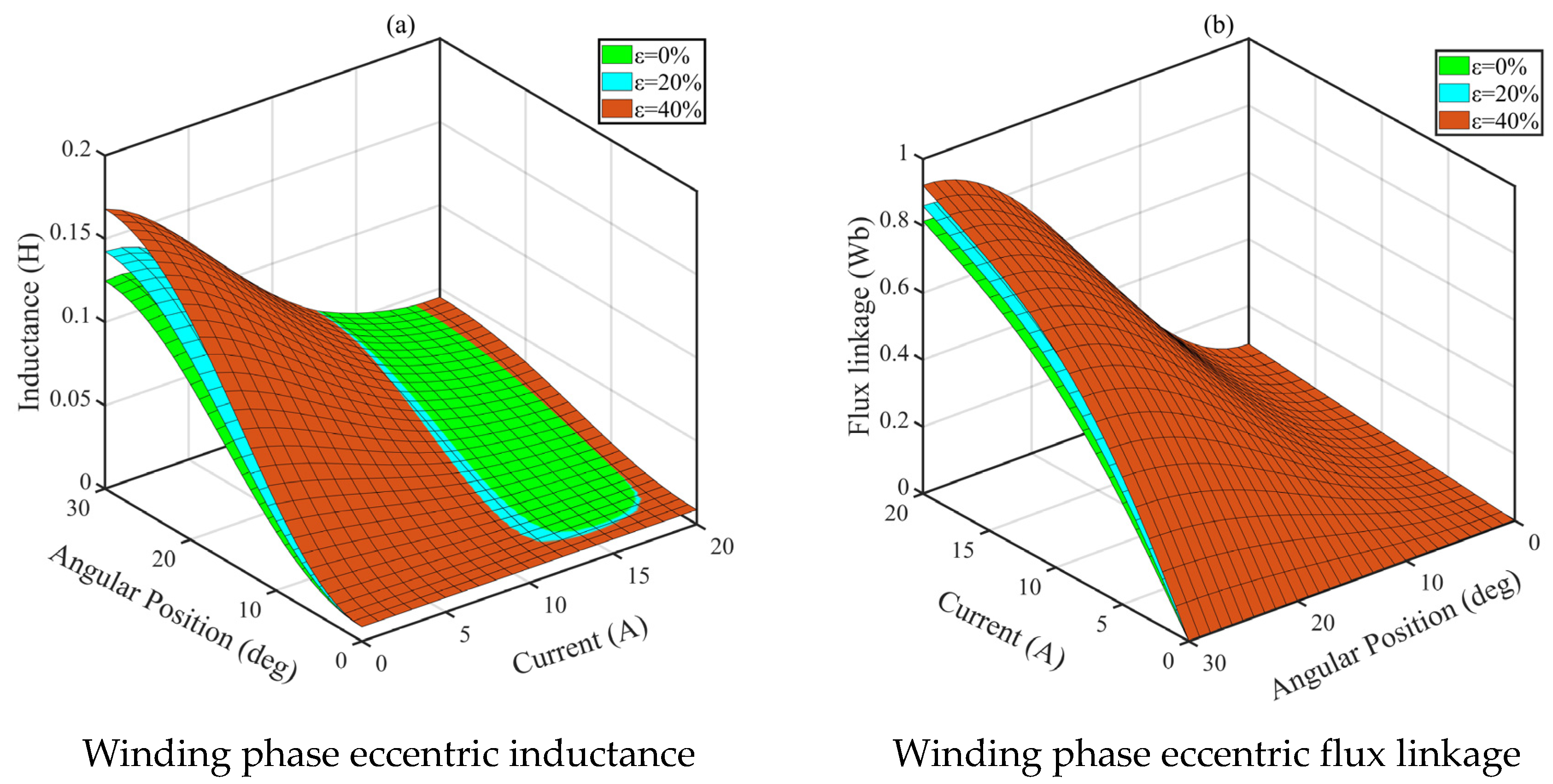
Assuming the Y-axis positive direction is the direction of air gap eccentricity, the electromagnetic characteristics of the winding phase inductance and winding phase magnetic flux with respect to the angle and current under different radial air gap eccentricities are obtained based on the inductance data for three unique positions of the switched reluctance motor, as shown in Figure 4. The figure shows that as the air gap eccentricity increases, the winding phase inductance and the magnetic flux increase. Additionally, with the increase in the overlap between the stator and rotor positions, the difference between the winding phase inductance and the winding phase magnetic flux under different eccentricities increases. Furthermore, from Figure 4a, it can be seen that there is some overlap in the inductance fitting accuracy under different eccentricities for currents ranging from 10A to 18A. However, further fitting of the winding phase magnetic flux shows that the fitting accuracy is within a reasonable range, with minimal impact on further analytical derivation of radial forces.
According to the principle of virtual work and the conversion of electromechanical energy, and neglecting the end effects of the motor stator and rotor poles and mutual inductance, the switched reluctance motor (SRM) is classified into tangential force and radial force output modes. The tangential force is output in the form of torque, driving the motor rotation, while the radial force is the leading cause of motor vibration. The static torque is obtained by the partial derivative of the magnetic coenergy with respect to the angle θ, and the partial derivative of the magnetic coenergy with respect to the air gap length Lg yields the radial force.
Furthermore, the mechanical characteristics of the SRM under different eccentricities can be obtained based on the inductance under different eccentricities. Therefore, the static torque and radial force under different eccentricities can be expressed as follows:
T e = 0 i ψ θ , i l g d i = sin ( N r θ ) n = 1 N 1 n e n 1 i k n + sin ( 2 N r θ ) n = 1 N 1 n f n 1 i k n
F r = W m L g | i = c o n s t = 0 i ψ θ , i L g d i = 1 2 i 2 L θ , i L g g
From the equation, en = Nrcn/2, e0 = 0, e1 = Nr (c1Lu)/2, fn = Nrdnen, f0 = 0, f1 = Nr (2d1c1Lu)/2.
According to Equations (8) and (9), the static magnetic torque and radial force under different air gap eccentricities are shown in Figure 5, illustrating the changes in the mechanical characteristics of the switched reluctance motor at a current of 3A. Analysis of the graph and Table 2 shows that under air gap eccentricity, the numerical radial force shift and static magnetic torque are directly proportional to the eccentricity, increasing as the eccentricity increases. Additionally, at an eccentricity of 40%, the radial force increases by 107.37%, while the static magnetic torque increases by 28.89%. Therefore, the impact of air gap eccentricity on radial force change is the most significant, and this paper only analyzes the change in radial force characteristics under air gap eccentricity.

2.4. Radial Force Calculation Under Tilt Eccentricity

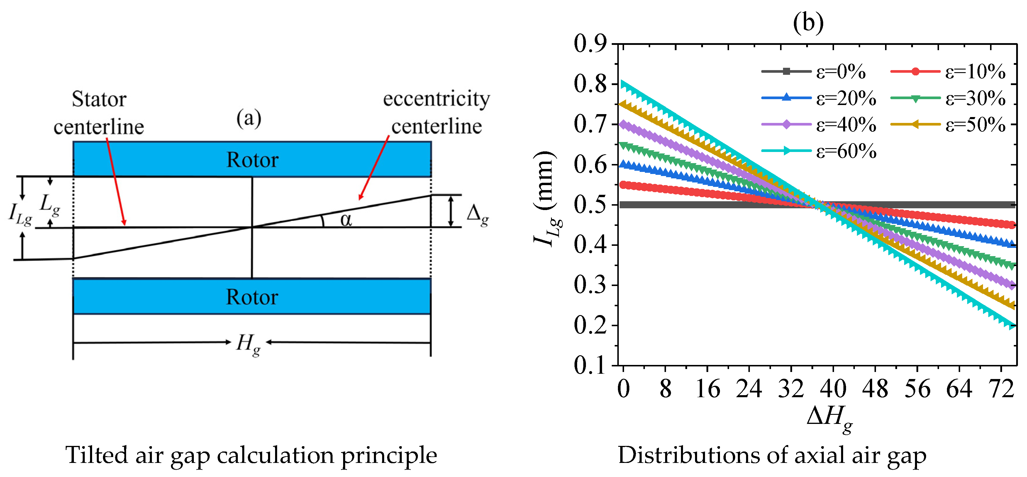
The analytical calculation of radial force under tilted air gap eccentricity can be obtained from the inductance data of radial air gap eccentricity and the axial distribution data of tilted air gap eccentricity. When the switched reluctance motor is in a tilted air gap eccentricity state, the calculation principle of the air gap between the stator and rotor is shown in Figure 6a, and Figure 6b shows the axial distribution of the air gap under different tilted eccentricities.
The axial air gap distribution of the switched reluctance motor under different tilted eccentricities can be obtained from the eccentric length ∆g and the axial length Hg of the switched reluctance motor. The specific expression is as follows:
α = arctan 2 Δ g H g
I L g = L g + tan α Δ H g ,    0 Δ H g < H g 2 L g tan α Δ H g ,    H g 2 Δ H g < H g
In the equation, ΔHg represents the axial length corresponding to each air gap position of the motor, α denotes the tilt angle of the motor, and ILg stands for the length of the air gap in the tilted air gap eccentricity state.
Figure 5b shows that the maximum change in radial force occurs when the stator and rotor poles overlap entirely in the air gap eccentricity state. Therefore, in this paper, the excitation current of the switched reluctance motor is set to 3 A. The winding at position B of the phase generates a tilted air gap eccentricity with respect to the X-axis. The calculation result of the radial force at one end of the stator and rotor poles, when they overlap completely, is shown in Figure 7.
The figure shows that under the tilted air gap eccentricity state, the change in radial force also exhibits a nonlinear tilting trend. As the eccentricity increases, the nonlinearity of the radial force trend gradually increases. Although the air gap at the center point remains the initial air gap, the radial force increases due to changes in the inductance under different eccentricities. Additionally, according to the “minimum reluctance principle,” magnetic flux lines tend to shorten the magnetic path and increase the magnetic conductivity to reduce reluctance. The magnetic flux always closes along the route with the minimum reluctance, causing a smaller decrease in radial force at positions with more significant air gaps and a more considerable increase in radial force at positions with the minimum air gap of the motor.

2.5. Radial Force Calculation of Each Winding Phase Under Eccentric Conditions

Since the air gap of the switched reluctance motor is annular, the air gap around the entire circumference will inevitably change when the motor produces an air gap eccentricity. Therefore, to investigate the variation of the radial forces of each phase winding in the air gap eccentricity state, phase winding B is set to have radial air gap eccentricity in the positive Y-axis direction.
Furthermore, based on the distribution of the circumferential angle of the center of each phase winding’s salient pole about the Y-axis in the stator and utilizing the lengths of the air gaps at different radial air gap eccentricities at the B-phase position, the lengths of the air gaps for different phase windings can be obtained. Then, the radial forces of different phase windings can be expressed as follows:
F r A = F r C = 1 2 i 2 L ( θ , i ) L g ± ( g cos ( π 4 ) ) F r B = 1 2 i 2 L ( θ , i ) L g ± ( g ) F r D = 1 2 i 2 L ( θ , i ) L g ± ( g cos ( π 2 ) )
In the equation, FrA, FrB, FrC, and FrD represent the radial forces of the four-phase windings of the switched reluctance motor.
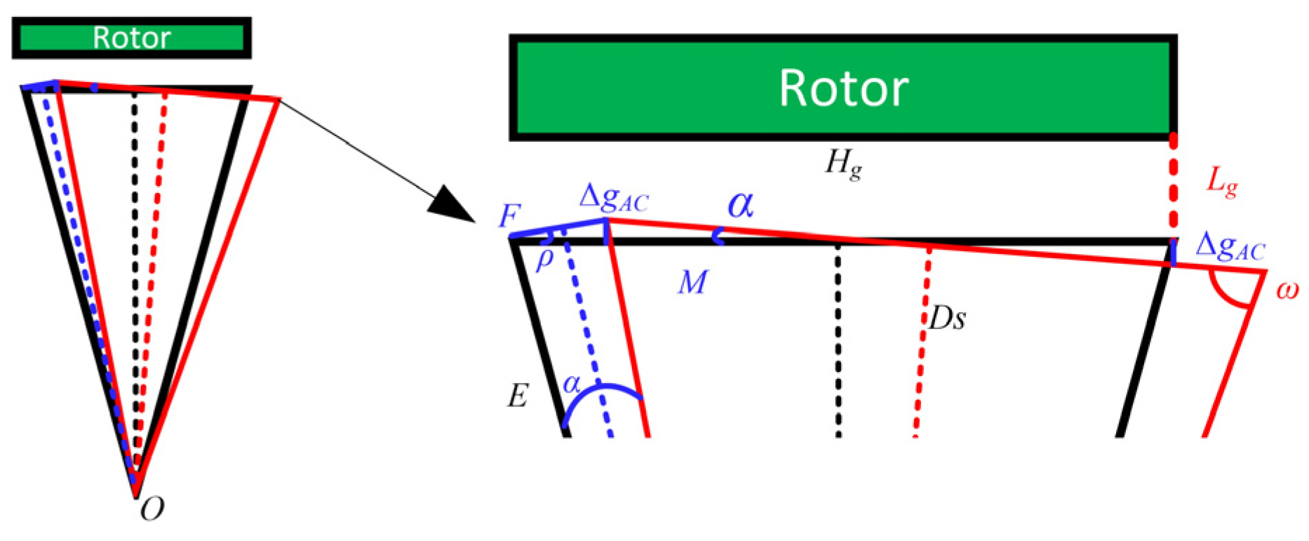
On the other hand, under the condition of tilted air gap eccentricity, the salient pole of phase winding B is also set to rotate with an inclination about the X-axis. Currently, the D-phase rotor salient pole and stator salient pole, perpendicular to the B-phase, only rotate around the X-axis, resulting in minimal changes in their air gaps. As for phase windings A and C, they share the same inclination angle α as phase winding B. Therefore, the principle for determining the air gap lengths of phase windings A and C is shown in Figure 8.
Further, the air gap lengths of phase windings A and C under tilted eccentricity can be calculated as follows:
ω = arctan 2 D s H g ;   ρ = π α 2 ω
E = D s sin ω ;   F = 2 sin α 2 E ; Δ g A C = tan α · H g 2 cos ρ F
I L g A C = L g + tan α · Δ H g 2 cos ρ F 0 Δ H g 2 cos ρ F < H g 2 cos ρ F L g tan α · Δ H g 2 cos ρ F H g 2 cos ρ F Δ H g 2 cos ρ F < H g 2 cos ρ F
The equation includes several variables: edge E represents the distance from the boundary of the stator pole to the center of the switched reluctance motor, edge F denotes the distance between the point after inclined eccentricity and the initial point without inclined eccentricity, ω is the angle between edge E and the surface of the stator pole, ρ is the angle between the point after inclined eccentricity and the surface of the stator pole at the initial position, ∆gAC is the length of the air gap eccentricity between phase windings A and C, Δ(Hg − 2cos (ρ)F) is the axial length of the motor corresponding to each air gap, and ILgAC is the air gap length between the stator and rotor in the case of inclined eccentricity.
Furthermore, the radial forces for different phase windings under various inclined eccentricities can be expressed as follows:
F r A = 1 2 i 2 L ( θ , i ) I L g A ;     F r B = 1 2 i 2 L ( θ , i ) I L g F r C = 1 2 i 2 L ( θ , i ) I L g C ;     F r D = 1 2 i 2 L ( θ , i ) L g
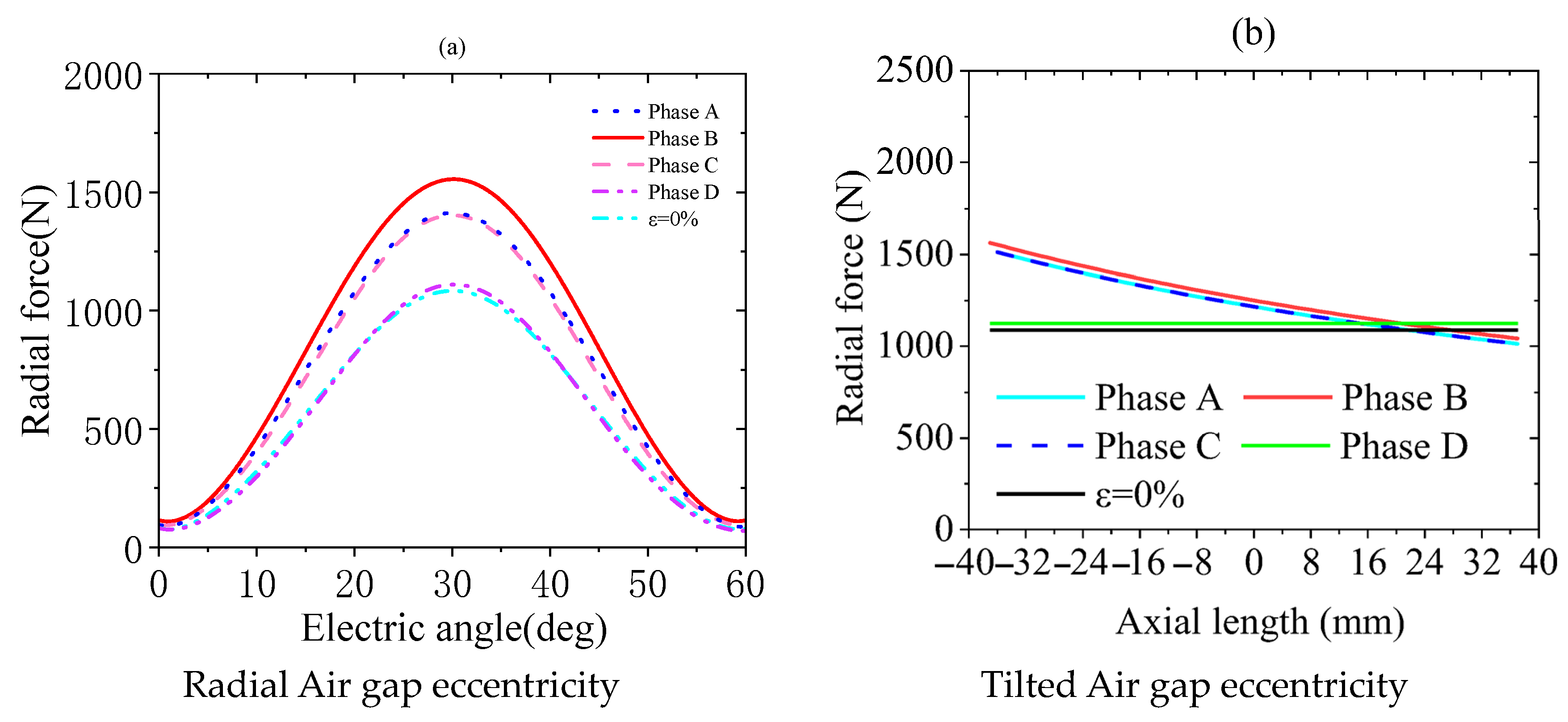
According to the formulas for eccentric inductance and radial force calculation for different phase windings under various eccentricities, assuming an eccentricity rate of 20% and an excitation current of 3 A, the mechanical characteristics of different phase windings of the switched reluctance motor are obtained, as shown in Figure 9.
The graph shows that among the four-phase windings of the switched reluctance motor, the radial force at the position of phase winding B undergoes the most significant numerical change in both types of eccentricities. The radial force changes for phase windings A and C are nearly identical, while the influence on the radial force of phase winding D is minimal. Furthermore, Figure 9b shows that the radial force at the position of phase winding D increases relative to the non-eccentric radial force. This increase is due to the finite element inductance data of phase winding D when the eccentricity rate is 20%, while the air gap length is assumed to remain constant, leading to an increase in the radial force. Additionally, analysis of Figure 9a,b shows an inverse proportionality between the radial force change and the air gap change; smaller air gaps result in larger radial forces. The radial force will remain relatively constant when there is no eccentricity or when the air gap change is small.

3. Influencing Factors of Radial Force Under Multi-Type Air Gap Eccentricity Conditions

Eccentricity is the primary cause of radial force imbalance in switched reluctance motors, which can lead to increased motor vibration. This section establishes a finite element model of the switched reluctance motor under eccentricity and analyzes the key factors affecting radial force variation using static magnetic field analysis.

3.1. Analysis of SRM Magnetic Flux Density

The Maxwell stress tensor method [27] considers the tension tensor of the magnetic field equivalent to inertial forces, where the inertial force of the magnetic field can be summarized as tension aligned with the magnetic field lines and lateral pressure perpendicular to the magnetic field lines. Therefore, the radial and tangential forces acting on the stator pole of the SRM can be expressed as follows:
F r = 1 2 μ 0 s B r 2 B t 2 d A
In the formula, μ0 is the vacuum magnetic permeability, Br is the radial magnetic flux density, Bt is the tangential magnetic flux density, and A is the area of the circumferential end surface s of the stator salient pole.
Furthermore, the radial magnetic flux density and tangential magnetic flux density of the SRM in the electromagnetic field can be expressed as follows:
B r = B x cos φ + B y sin φ B t = B y cos φ B x sin φ
In the formula, φ is the spatial angle formed by the solution point and the x-axis; Bx and By are the horizontal and vertical components of the magnetic flux density in the Cartesian coordinate system, and their distribution is shown in Figure 10.
For a given structure of a switched reluctance motor, the magnetic flux density between the stator and rotor is inevitably affected by air gap eccentricity. According to Equation (18), a finite element simulation analysis of the magnetic flux density between the stator and rotor poles of the motor was conducted, resulting in the spatial distribution of radial and tangential magnetic flux densities at different eccentricities relative to the rotor position. These distributions are shown in Figure 11 and Figure 12, where “Distance” represents the integral path length along the arc of the stator pole.
Regarding radial magnetic flux density, Figure 11 shows that the maximum distribution area occurs at a rotor position of 30 degrees, exhibiting a fluctuating trend along the arc length of the stator pole. The radial magnetic flux density reaches its maximum value at the boundary of the stator pole, where the radial force fluctuation amplitude is also the largest. Additionally, comparing Figure 11a and Figure 11c, it can be observed that under eccentricity, both the fluctuation trend and the magnitude of the radial magnetic flux density increase with eccentricity.
On the one hand, the tangential magnetic flux density exhibits a distribution pattern where one side has the maximum value, while the other side has the minimum value and shows fluctuating variations. Different eccentricity ratios have minimal effect on the change in tangential magnetic flux density.
In summary, the radial magnetic flux density exhibits more significant fluctuations under eccentricity conditions. The widths of the stator and rotor poles are the main factors determining the extent of the influence on the radial magnetic flux density, and their various aspects will further affect the radial force variation. Therefore, it is necessary to analyze the effect of the structural parameters of the switched reluctance motor on the radial force.

3.2. The Impact of Structural Parameters on Radial Force

Due to the unique dual-pole structure of the switched reluctance motor (SRM), changes in the widths of the stator and rotor poles, as well as the yoke height, will affect the magnetic flux density distribution and consequently influence the radial force of the SRM. Based on the established finite element model, the radial force variation characteristics at the B-phase winding position are analyzed for different structural parameters. To ensure the self-starting capability of the SRM, constraints are imposed on the pole arc angle and yoke height, as follows:
min ( β s ,   β r ) 2 π q N r , β s + β r 2 π N r
L s b p s 2 ,   L r b p r 2
In the equation, q represents the number of phases in the SRM; bps is the stator pole width; bpr is the rotor pole width; βs is the stator pole arc angle; βr is the rotor pole arc angle.
Under radial air gap eccentricity, the radial force mainly occurs between the stator and rotor poles. This section selects the average radial force between the stator and rotor poles as the evaluation index. The radial force under different structural parameter variations is shown in Figure 13. The figure shows that when the eccentricity is below 20%, the structural parameter variations of the switched reluctance motor have little effect on the radial force. However, as the eccentricity increases to 40%, the radial force begins to fluctuate, and the influence of structural parameters on the radial force increases. Among them, the structural parameters Dr and Hs have the most significant impact, while the variations in other structural parameters have a lesser impact.
On the other hand, in the tilted eccentricity state, the radial force acting on the rotor surface will exert an unbalanced torque, denoted as UM, on the wheel motor. Therefore, the change in torque value is used as an evaluation index, and the following formula can calculate UM:
T u = T u ( 1 ) + T u ( 2 ) T u ( 1 ) = H g | F r ( 1 ) F r ( u ) | d s T u ( 2 ) = H g | F r ( 2 ) F r ( m ) | d s
In the equation, Fr(1) and Fr(2) are the radial forces at one end of the stator poles of the switched reluctance motor in the tilted eccentricity state. Meanwhile, Fr(u) and Fr(m) are the radial forces at one end of the stator poles of the switched reluctance motor in the absence of eccentricity.
The variation of the unbalanced radial force moment under different structural parameters is shown in Figure 14. It can be seen from the figure that when the eccentricity is 20%, the structural parameters Dr and Ds have the most significant impact. When the eccentricity is 40%, except for the structural parameter Lr, the other structural parameters significantly impact the unbalanced radial force moment. The reason is that in the tilted eccentricity state, the stator’s outer diameter, the stator and rotor poles, and the height of the stator yoke are the main structural parameters affecting the variation of the motor air gap. When the widths of the stator and rotor poles are close to each other, with the initial width of the rotor pole at 53.231 mm and the initial width of the stator pole at 50.755 mm, the fluctuation of the unbalanced radial force moment is minimized. Therefore, to reduce the unbalanced radial force moment, the widths of the stator and rotor poles should be close to each other.

3.3. Radial Force Characteristics of Each Winding Phase Under Eccentric Conditions

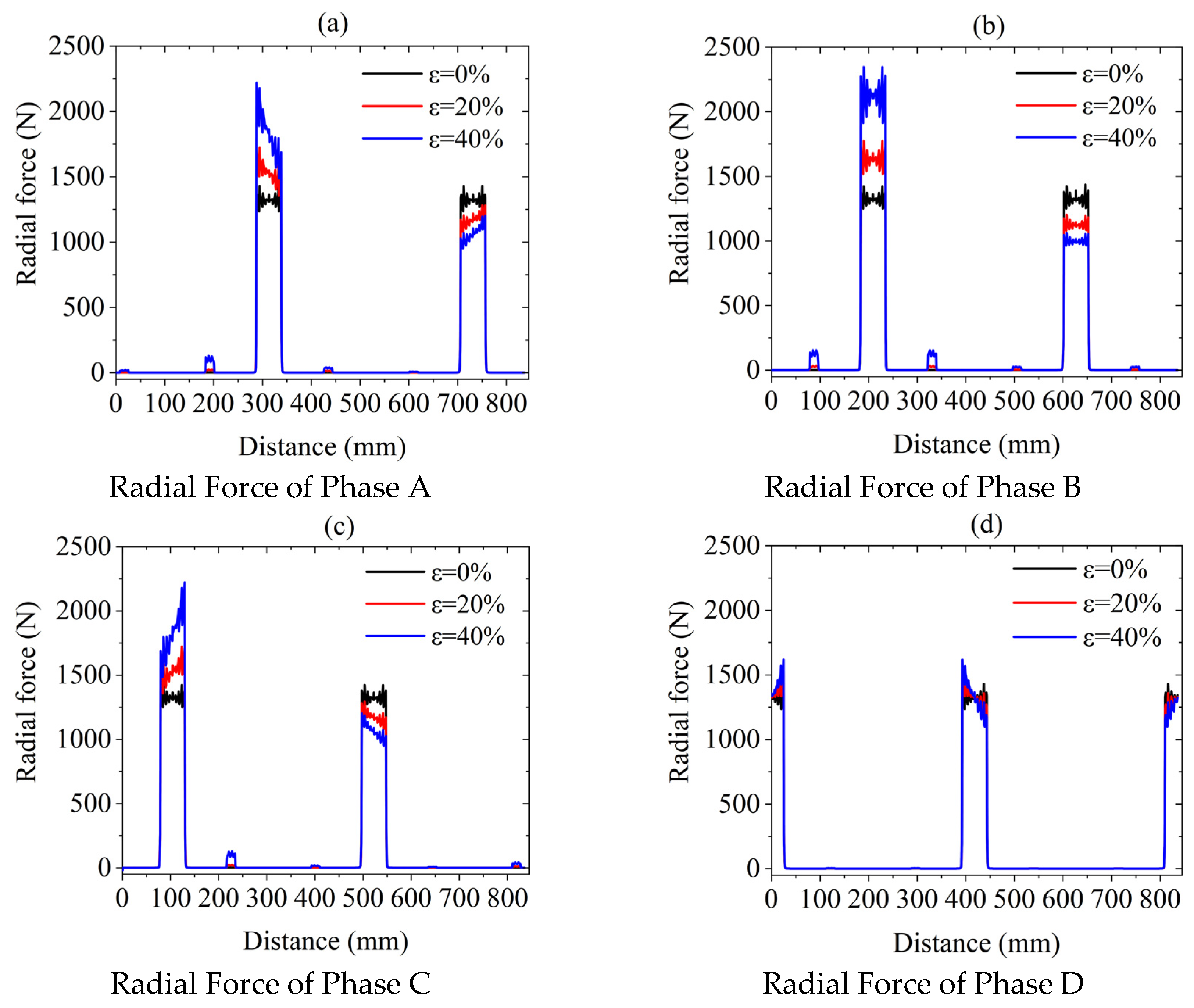
Based on the previous analysis, it is known that eccentricity will cause changes in the circumferential air gap. This section uses the finite element method to analyze the variation characteristics of radial force under spatial structure. Figure 15 shows the radial forces on the stator circumferential surface when each winding phase is energized under radial eccentricity. When there is no air gap eccentricity, the radial forces at both ends of the stator poles and each phase position of the winding remain equal. After introducing the air gap eccentricity, the radial force at one end of the stator poles increases while it decreases at the other. The radial forces of phase A and phase C show a symmetrical and almost identical trend, while the air gap variation at the position of phase D is minimal. The radial force at the position of phase B does not show any tilting variation because the radial air gap eccentricity changes along the centerline of phase B, resulting in a uniform and gradual decrease in the air gap between the stator and rotor. Furthermore, when different winding phases are energized, although the adjacent winding phases are not energized, they still produce smaller radial forces after introducing air gap eccentricity.
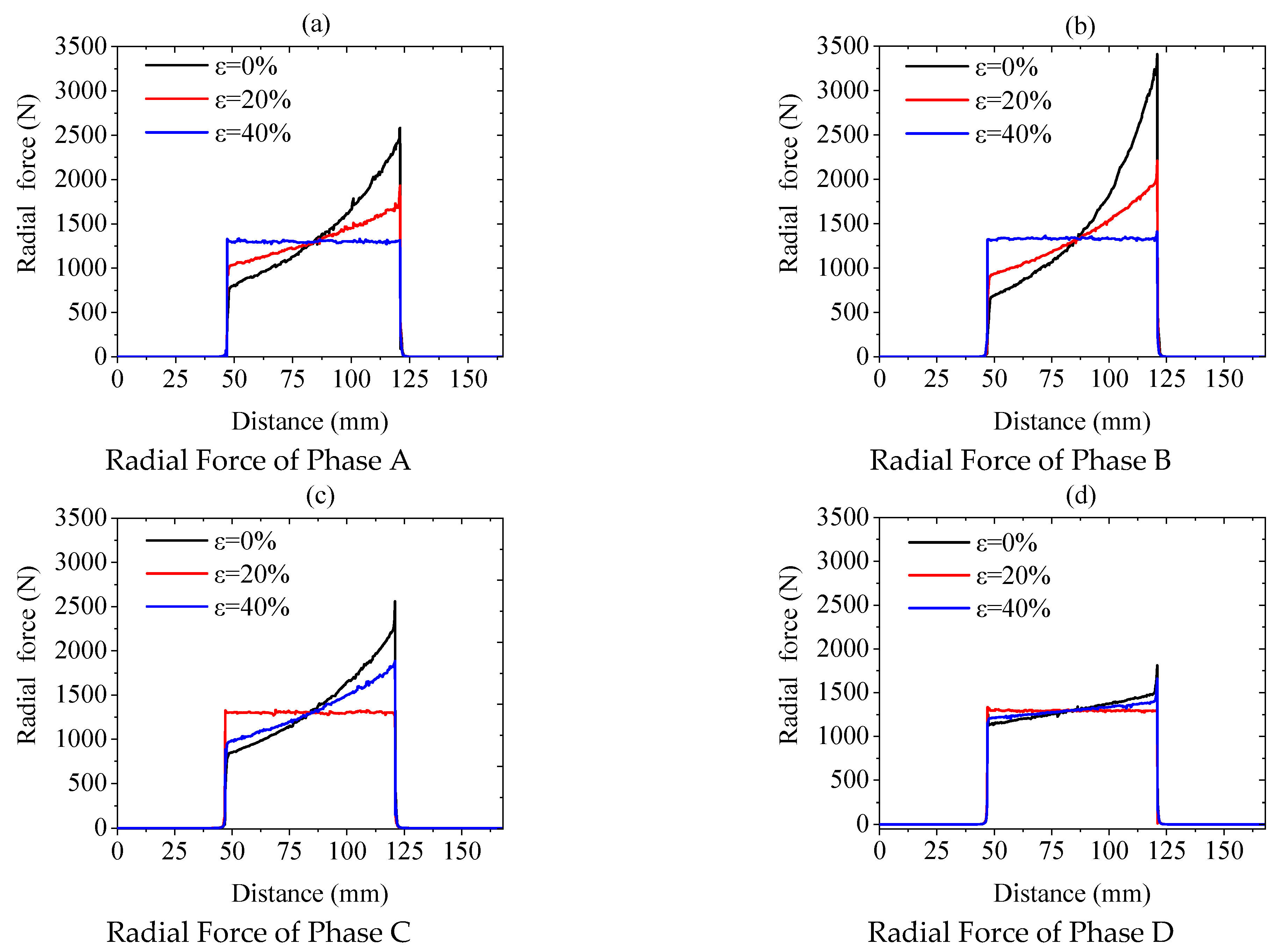
Furthermore, the variation of radial force under tilted air gap eccentricity is shown in Figure 16, where Distance in Figure 16a–d represents the axial distance from the rotor pole. It can be observed from the figure that the radial force variations of different winding phases exhibit some similar patterns to those under radial air gap eccentricity. For example, the radial force variations of phases A and C are identical; phase D shows the smallest radial force variation, and phase B exhibits the largest. As the eccentricity increases, the tilting trend of the radial force becomes more severe, and radial force peaks appear at both ends of the rotor. Additionally, during tilted air gap eccentricity, the axial profiles of the stator and rotor poles are not at the same horizontal position. However, the radial magnetic flux will permanently close along the path of minimum reluctance. This results in slightly larger radial force values than those under radial air gap eccentricity at the same current.

4. Experimental Verification of Radial Force Numerical Results

To verify the accuracy of the analytical calculation of radial force using the Fourier series method, which is a prerequisite for investigating the detrimental effects of hub motors on vehicle dynamics, experimental techniques and a setup for measuring radial force were employed in this section. The goal was to validate the calculated radial force results for various air gap eccentricities and different phases of the switched reluctance motors.

4.1. Develop Test Methods and Build Measurement Benches

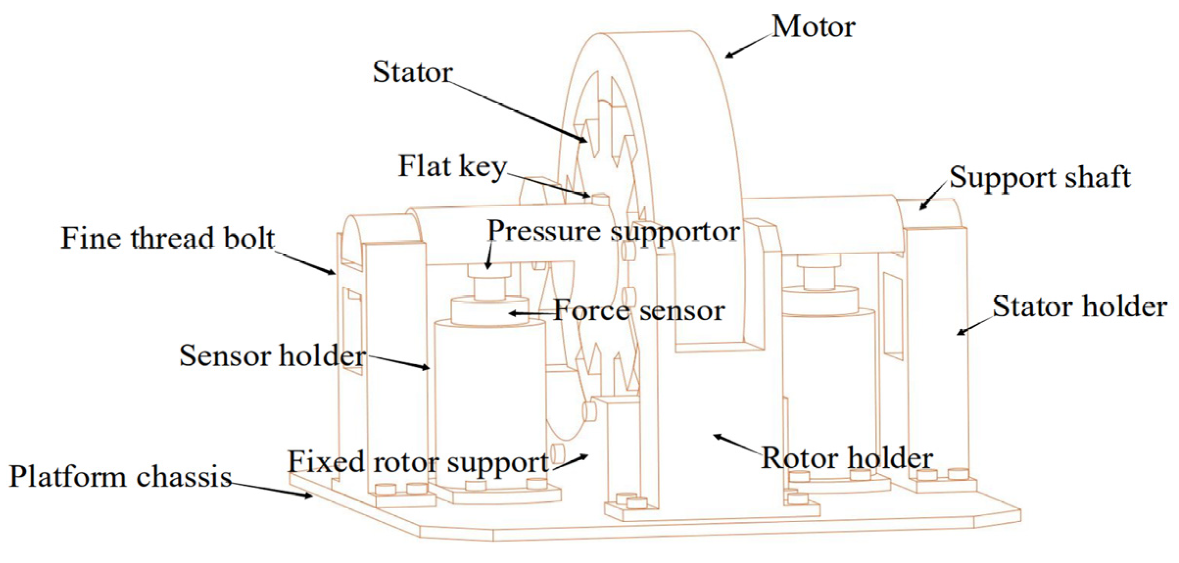
A radial force measurement setup was established in this section to accommodate radial force measurements for various types of air gap eccentricities and different phases of the switched reluctance motor, as shown in Figure 17. The radial force measurement setup mainly consists of the rotor and its fixed bracket, the stator and its fixed bracket, sensors and their brackets, a platform base, and a stator support shaft. The components of this measurement setup are connected using bolts or keys. All other fixed brackets are bolted to the platform base, except for the rotor fixed base. A critical interference fit connects the stator and support shaft. Four threaded bolts support the stator support shaft below, ensuring it can perform horizontal, vertical, and tilted movements. The pressure point above the pressure sensor is fixed and connected by a threaded hole, allowing for the adjustment of the pressure point height.
Four fine-tooth bolts on the stator bracket adjust the air gap between the stator and rotor. Rotating these bolts can vertically move the stator by adjusting two fine-tooth bolts on one side of the stator bracket or by adjusting the movable stator fixed bracket to tilt the stator. The relative positions of each phase of the windings in the same air gap eccentricity state can be changed by adjusting the eight movable bolt holes under the stator fixed bracket to move the stator shaft horizontally, rotating the switched reluctance motor rotor to complete the pole-to-pole position of the stator and rotor for different phases of the windings, and using an angle scale to correct the relative position of the stator and rotor. Then, the rotor was fixed to prevent it from rotating using 14 bolts on the rotor bracket and the fixed base. After completing the above operations, the pressure point above the pressure sensor was adjusted to keep the stator support shaft undisturbed except for gravity. Then, the fine-tooth bolts on the stator fixed bracket were retracted by a certain distance. Finally, the current of the DC stabilized power supply was adjusted in real time to record the pressure sensor results on the computer, completing the radial force measurement for different currents and different types of air gap eccentricities.
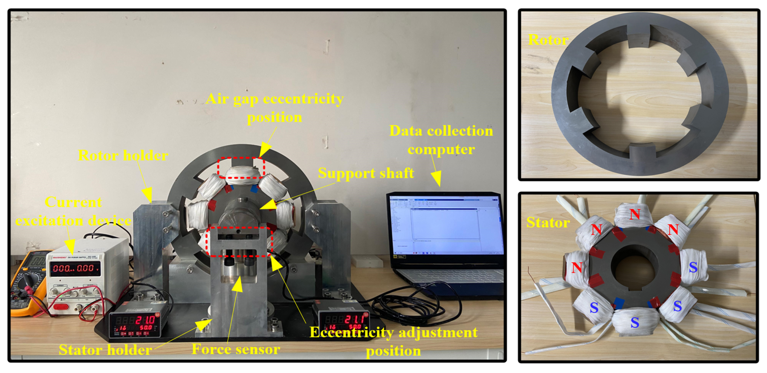
Each phase winding of the switched reluctance motor is wound with 137 turns of pure copper enameled wire to enable precise measurement of the radial force values of the various phase windings. The relevant equipment and their purposes for measuring the radial force according to the above experimental method are shown in Table 3. The constructed radial force measurement platform is shown in Figure 18.

4.2. Experiment Result

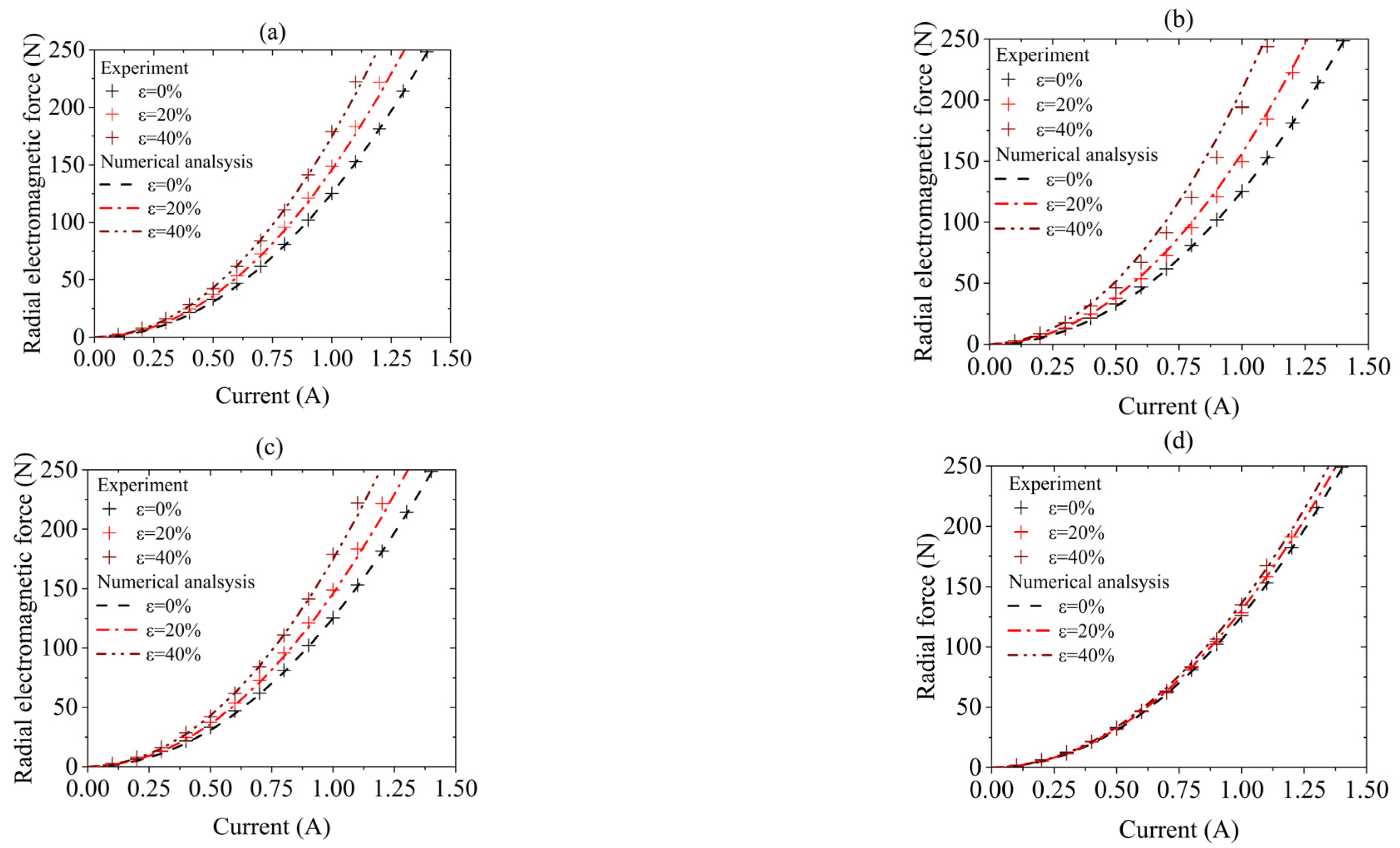
Based on the above experimental method and radial force measurement platform, the radial force values of the switched reluctance motor at the pole-to-pole position were measured. The measured radial forces of different phase windings under various radial air gap eccentricity states and current magnitudes are shown in Figure 19, which c ontains four subfigures depicting the spatial configurations of the motor windings: (a) A-phase winding, (b) B-phase winding, (c) C-phase winding, and (d) D-phase winding. The results indicate good agreement between measured radial forces and numerical analysis, demonstrating the accuracy of the calculation method. This confirms the reliability of these results for subsequent vehicle dynamics analysis.
On the other hand, there is no bearing between the stator and the rotor. When the current continuously increases, the radial force between the stator and rotor of the switched reluctance motor will exceed the total gravity of the stator and stator support shaft. The stator and support shaft will be displaced due to the radial force, affecting the eccentricity accuracy. Therefore, to ensure the accuracy of the radial force measurement, after multiple measurements and verification, the measurement threshold of the radial force measurement platform is set to 250 N.
Furthermore, under experimental verification conditions, the unbalanced radial moment in the eccentric state of the inclined air gap can be expressed as follows:
T u = T u ( 1 ) + T u ( 2 ) T u ( 1 ) = H g | F r ( 1 ) F r ( u ) | d s = l | f r ( 1 ) f r ( u ) | d s T u ( 2 ) = H g | F r ( 2 ) F r ( m ) | d s = l | f r ( 2 ) f r ( m ) | d s
fr(1) and fr(2) are the measured radial forces under tilted air gap eccentricity. At the same time, fr(u) and fr(m) are the measured radial forces with no air gap eccentricity. The distance between the two pressure points is 135 mm.
To ensure the validity of the experimental results, only the radial forces at a tilted air gap eccentricity of 20% were measured, with a set current excitation value of 1 A. The measurement results are shown in Table 4. According to the previous analysis, the radial force at the position of phase D winding under tilted air gap eccentricity has a minor effect. Therefore, this section only measures the radial forces of phases A, B, and C. Additionally, under the same air gap eccentricity condition, the radial force caused by tilted air gap eccentricity is slightly greater than that caused by radial air gap eccentricity.
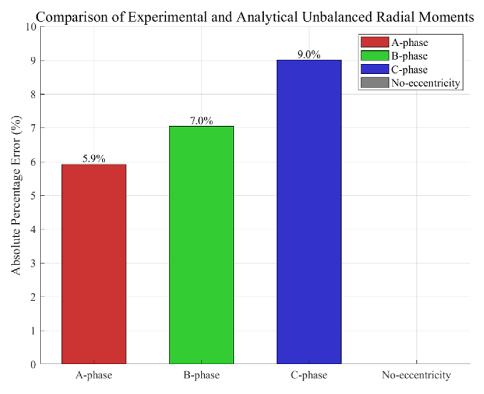
From the unbalanced radial force moment results, it can be seen that the experimental measurement results are close to the numerical analysis results; the errors in phases A, B, and C are 5.9%, 7%, and 9% of the resolved values, respectively, and none of them exceeds 10%, as shown in Figure 20, effectively verifying that the measurement platform meets the requirements for measuring unbalanced radial force moments under certain conditions.

5. Conclusions

This paper proposes a method for calculating the radial force of a switched reluctance motor under multiple types of air gap eccentricities. The method considers changes in motor structural parameters and calculates radial forces under different winding conditions. The switched reluctance motor’s air gap eccentricity inductance data is obtained using finite element analysis, and the air gap length at different winding positions is calculated. This allows for determining the radial force values under different winding conditions and types of air gap eccentricities. The influence of structural parameters of the switched reluctance motor on the radial force under two kinds of air gap eccentricities is analyzed through finite element analysis. Finally, a method for measuring the radial force of a switched reluctance motor with multiple types of air gap eccentricities is developed, and a radial force measurement platform is built to validate the effectiveness and accuracy of the proposed radial force calculation method. Furthermore, this method can calculate the radial force at each point on the motor by computing the air gap length at each end, providing a theoretical basis for studying radial force calculation in cases of complex air gap eccentricities. It is also capable of providing more accurate mechanical analysis tools for the design of electric motors, offering theoretical support for fault diagnosis and health management in practical engineering applications.

Author Contributions

The manuscript including modeling and simulation was carried out by C.Y. (Chao Yang). The analysis of data was performed by W.J. and S.J., who also contributed to writing-original draft preparation. The experiment was operated by C.Y. (Chuanxing Yang), who also contributed to manuscript correction under the supervision of C.Y. (Chao Yang). All authors have read and agreed to the published version of the manuscript.

Funding

This work is supported by the Key Research and Development Promotion Special Project (Science and Technology Research Project) of Henan Province (Grant No.232102240048) and (Grant No.252102240114).

Data Availability Statement

The raw data supporting the conclusions of this article will be made available by the authors on request.

Conflicts of Interest

The authors declare no conflict of interest.

References

  1. Martínez Lao, J.; Montoya, F.G.; Montoya, M.G.; Manzano-Agugliaro, F. Electric vehicles in Spain: An overview of charging systems. Renew. Sustain. Energy Rev. 2017, 77, 970–983. [Google Scholar] [CrossRef]
  2. Fernandes, J.C.M.; Gonçalves, P.J.P.; Silveira, M. Interaction between asymmetrical damping and geometrical nonlinearity in vehicle suspension systems improves comfort. Nonlinear Dyn. 2020, 99, 1561–1576. [Google Scholar] [CrossRef]
  3. Li, J.; Yang, S.; Li, Z.; Gou, L. An Energy Conservation Strategy Based on Drive Mode Switching for Multi-Axle In-wheel Motor Driven Vehicle. Energy Procedia 2019, 158, 2580–2585. [Google Scholar] [CrossRef]
  4. Wang, Q.; Li, R.; Zhu, Y.; Du, X.; Liu, Z. Integration design and parameter optimization for a novel in-wheel motor with dynamic vibration absorbers. J. Braz. Soc. Mech. Sci. Eng. 2020, 42, 1–12. [Google Scholar] [CrossRef]
  5. Fatemi, A.; Lahr, D. A Comparative Study of Cycloidal Reluctance Machine and Switched Reluctance Machine. IEEE Trans. Energy Convers. 2021, 36, 1852–1860. [Google Scholar] [CrossRef]
  6. Abdalmagid, M.; Sayed, E.; Bakr, M.H.; Emadi, A. Geometry and topology optimization of switched reluctance machines: A review. IEEE Access 2022, 10, 5141–5170. [Google Scholar] [CrossRef]
  7. Yang, X.; Song, H.; Shen, Y.; Liu, Y. Study on adverse effect suppression of hub motor driven vehicles with inertial suspensions. Proc. Inst. Mech. Eng. Part D J. Automob. Eng. 2022, 236, 767–779. [Google Scholar] [CrossRef]
  8. Yang, X.; Song, H.; Shen, Y.; Liu, Y.; He, T. Control of the vehicle inertial suspension based on the mixed skyhook and power-driven-damper strategy. IEEE Access 2020, 8, 217473–217482. [Google Scholar] [CrossRef]
  9. Hu, Y.; Li, Y.; Li, Z.; Zheng, L. Analysis and suppression of in-wheel motor electromagnetic excitation of IWM-EV. Proc. Inst. Mech. Eng. Part D J. Automob. Eng. 2021, 235, 1552–1572. [Google Scholar] [CrossRef]
  10. Tan, D.; Wang, H.; Wang, Q. Study on the rollover characteristic of in-wheel-motor-driven electric vehicles considering road and electromagnetic excitation. Shock. Vib. 2016, 2016, 2450573. [Google Scholar] [CrossRef]
  11. Li, Z.; Liu, C.; Song, X.; Wang, C. Vibration suppression of hub motor electric vehicle considering unbalanced magnetic pull. Proc. Inst. Mech. Eng. Part D J. Automob. Eng. 2021, 235, 3185–3198. [Google Scholar] [CrossRef]
  12. Guo, B.; Du, Y.; Peng, F.; Huang, Y. Magnetic field calculation in axial flux permanent magnet motor with rotor eccentricity. IEEE Trans. Magn. 2022, 58, 1–4. [Google Scholar] [CrossRef]
  13. Zhang, X.; Zhang, B. Analysis of magnetic forces in axial-flux permanent-magnet motors with rotor eccentricity. Math. Probl. Eng. 2021, 2021, 1–8. [Google Scholar] [CrossRef]
  14. Xu, M.X.; He, Y.L.; Zhang, W.; Dai, D.R.; Liu, X.A.; Zheng, W.J.; Wan, S.T.; Gerada, D.; Shi, S.Z. Impact of Radial Air-Gap Eccentricity on Stator End Winding Vibration Characteristics in DFIG. Energies 2022, 15, 6426. [Google Scholar] [CrossRef]
  15. He, Y.L.; Sun, Y.X.; Xu, M.X.; Wang, X.L.; Wu, Y.C.; Vakil, G.; Gerada, D.; Gerada, C. Rotor UMP characteristics and vibration properties in synchronous generator due to 3D static air-gap eccentricity faults. IET Electr. Power Appl. 2020, 14, 961–971. [Google Scholar] [CrossRef]
  16. He, Y.L.; Li, Y.; Zhang, W.; Xu, M.X.; Bai, Y.F.; Wang, X.L.; Shi, S.Z.; Gerada, D. Analysis of stator vibration characteristics in synchronous generators considering inclined static air gap eccentricity. IEEE Access 2022, 11, 7794–7807. [Google Scholar] [CrossRef]
  17. Xing, Z.; Wang, X.; Zhao, W. Electromagnetic Vibration Reduction of Surface-Mounted Permanent Magnet Synchronous Motors Based on Eccentric Magnetic Poles. J. Electr. Eng. Technol. 2023, 18, 3603–3614. [Google Scholar] [CrossRef]
  18. Galfarsoro, U.; McCloskey, A.; Zarate, S.; Hernández, X.; Almandoz, G. Influence of Manufacturing Tolerances and Eccentricities on the Electromotive Force in Permanent Magnet Synchronous Motors. In Proceedings of the 2022 International Conference on Electrical Machines (ICEM), Valencia, Spain, 5–8 September 2022. [Google Scholar]
  19. Teng, X.; Li, Y.; Zhang, B.; Feng, G.; Liu, Z. Analysis and weakening of radial electromagnetic forces in high-speed permanent magnet motors with external rotors based on shape functions. IET Electr. Power Appl. 2023, 17, 656–669. [Google Scholar] [CrossRef]
  20. Li, X.; Deng, Z.; Liu, T.; Zhao, S. Analytical representation and characteristics optimization for radial electromagnetic force of the switched reluctance motor under airgap eccentricity. Proc. Inst. Mech. Eng. Part C J. Mech. Eng. Sci. 2022, 236, 7629–7640. [Google Scholar] [CrossRef]
  21. Liang, W.; Wang, J.; Luk, P.C.K.; Fei, W. Analytical study of stator tooth modulation on electromagnetic radial force in permanent magnet synchronous machines. IEEE Trans. Ind. Electron. 2020, 68, 11731–11739. [Google Scholar] [CrossRef]
  22. Wang, F.; Wu, Z.; Li, X. Analytical modelling of radial coupled vibration and superharmonic resonance in switched reluctance motor. J. Vib. Eng. Technol. 2021, 9, 449–467. [Google Scholar] [CrossRef]
  23. Deng, Z.; Luo, X.; Liao, X.; Li, X.; Du, Z.; Hou, M.; Wei, H. Analysis and suppression of the negative effect of electromagnetic characteristics of wheel hub motor drive system on vehicle dynamics performance. Nonlinear Dyn. 2025, 113, 4425–4445. [Google Scholar] [CrossRef]
  24. Khalil, A.; Husain, I. A fourier series generalized geometry-based analytical model of switched reluctance machines. IEEE Trans. Ind. Appl. 2007, 43, 673–684. [Google Scholar] [CrossRef]
  25. Ye, Z.Z.; Martin, T.W.; Balda, J.C. Modeling and nonlinear control of a switched reluctance motor to minimize torque ripple. In Proceedings of the Smc 2000 Conference Proceedings. 2000 IEEE International Conference on Systems, Man and Cybernetics. Cybernetics Evolving to Systems, Humans, Organizations, and Their Complex Interactions Cat, Nashville, TN, USA, 8–11 October 2000; Volume 5. [Google Scholar]
  26. Mahdavi, J.; Suresh, G.; Fahimi, B.; Ehsani, M. Dynamic modeling of nonlinear SRM drive with Pspice. In Proceedings of the IAS’97. Conference Record of the 1997 IEEE Industry Applications Conference Thirty-Second IAS Annual Meeting, New Orleans, LA, USA, 5–9 October 1997; Volume 1. [Google Scholar]
  27. Krishnamurthy, M.; Edrington, C.S.; Emadi, A.; Asadi, P.; Ehsani, M.; Fahimi, B. Making the case for applications of switched reluctance motor technology in automotive products. IEEE Trans. Power Electron. 2006, 21, 659–675. [Google Scholar] [CrossRef]
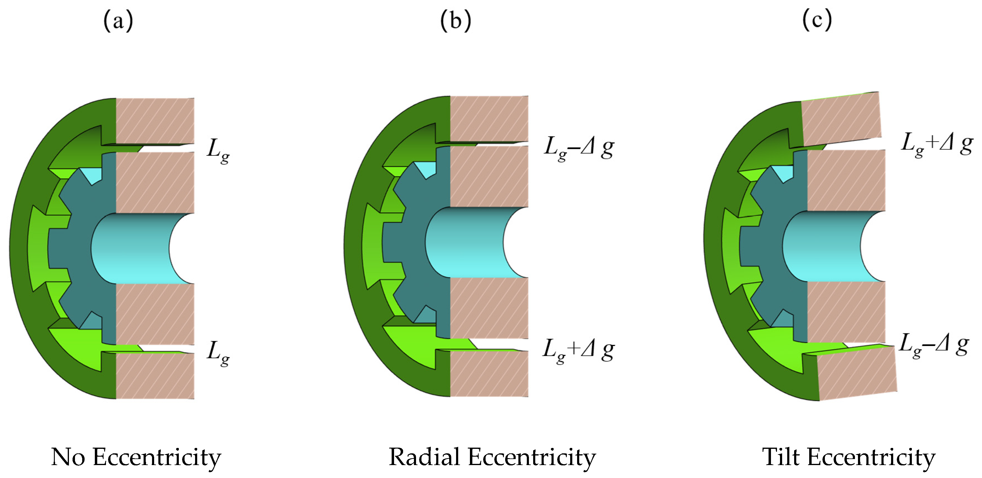
Figure 1. Schematic diagrams of air gap eccentricity types.
Wevj 16 00473 g001
Figure 2. Structure of the outer rotor 8/6-pole SRM.
Wevj 16 00473 g002
Figure 3. Fourier fitting curve of inductance at a unique position.
Wevj 16 00473 g003
Figure 4. Electromagnetic characteristics of SRM under different eccentricities.
Wevj 16 00473 g004
Figure 5. Mechanical properties of SRM under different eccentricities.
Wevj 16 00473 g005
Figure 6. SRM tilted air gap calculation principle and distribution.
Wevj 16 00473 g006
Figure 7. Radial force of SRM under different tilt air gap eccentric conditions.
Wevj 16 00473 g007
Figure 8. Schematic diagram of the air gap solution for winding A and winding C under the tilted air gap eccentric condition.
Wevj 16 00473 g008
Figure 9. SRM winding phase radial force.
Wevj 16 00473 g009
Figure 10. SRM flux density distribution.
Wevj 16 00473 g010
Figure 11. Spatial distribution of radial magnetic flux density under different eccentricities.
Wevj 16 00473 g011
Figure 12. Spatial distribution of tangential magnetic flux density under different eccentricities.
Wevj 16 00473 g012
Figure 13. Different structural parameter variables of REF for radial air gap eccentricity.
Wevj 16 00473 g013aWevj 16 00473 g013b
Figure 14. Different structural parameter variables of UM for radial air gap eccentricity.
Wevj 16 00473 g014aWevj 16 00473 g014b
Figure 15. Radial force of each winding at the pole-to-pole position under horizontal eccentricity.
Wevj 16 00473 g015
Figure 16. Radial force of each winding at the pole-to-pole position under tilt eccentricity.
Wevj 16 00473 g016
Figure 17. Design of SRM multi-type air gap eccentric radial force measurement bench.
Wevj 16 00473 g017
Figure 18. SRM multi-type air gap eccentric radial force measurement bench.
Wevj 16 00473 g018
Figure 19. Measurement results of radial force under radial eccentricities.
Wevj 16 00473 g019
Figure 20. Unbalanced radial moment measurement error chart.
Wevj 16 00473 g020
Table 1. Structure parameters of the SRM.
ParametersValueParametersValue
Rotor Diameter Dr/mm382Rotor Pole Arc βr/deg23
Stator Diameter Ds/mm266Stator Pole Arc βs/deg22
Shaft Diameter Dsh/mm90Rotor Yoke Lr/mm32
Air-gap Length Lg/mm0.5Stator Yoke Ls/mm46
Stack Length Hg/mm74Number of Turns Nc/-136
Table 2. Mechanical characteristics change under different air gap eccentricities.
Rotor PositionParametersε = 0%ε = 20%ε = 40%
30 degRadial Force1082.13 N/-1495.35 N/38.19%2243.96 N/107.37%
15 degStatic Torque1.80 Nm/-2.02 Nm/12.22%2.32 Nm/28.89%
Table 3. Components of the RF Measurement Bench.
ComponentsFunctions
Regulated DC power supplySupplies stable DC excitation voltage to the coil windings
DCC test leade Connects the DC power source to the winding terminals
Load application pointSupports the stator shaft during force
application
Spoke-type load cell (0 kg–800 kg)Measures the radial force (RF) applied
during testing
Force display controllerDisplays and manages radial force
readings
Digital multimeterMonitors the current flowing through the
winding coils
Precision feeler gauge (0.05 mm–1.00 mm)Measures and verifies air-gap eccentricity
Angular protractorAssists in adjusting winding phase and rotor-stator alignment
Laptop computerPerforms data acquisition, processing, and analysis
Table 4. Unbalanced moment under tilted eccentricities.
PhaseValue of Pressure SensorNumerical Value of Radial Force/NUnbalanced Moment/Nm
LeftRightLeftRightExperimentalNumerical
A119.8152.599.89227.852.2272.367
B117.9152.1102.7239.62.3092.484
C120.1153.599.90227.832.1532.366
No ecc135.1135.1125.28125.2800
Disclaimer/Publisher’s Note: The statements, opinions and data contained in all publications are solely those of the individual author(s) and contributor(s) and not of MDPI and/or the editor(s). MDPI and/or the editor(s) disclaim responsibility for any injury to people or property resulting from any ideas, methods, instructions or products referred to in the content.