1. Introduction
Motor–generator sets (MGs) play a pivotal role in a wide range of commercial applications, from temporary power systems and hybrid vehicles to integrated renewable energy systems [
1,
2]. Ensuring their reliable and efficient operation is essential, and among the various influencing factors, thermal management stands out as a critical aspect. Overheating, especially in the stator windings, can lead to insulation degradation, increased operational costs, and ultimately shorter useful life of equipment [
3].
Cooling technologies for electric motors have evolved significantly, transitioning from natural air cooling and fan-assisted convection to advanced liquid cooling systems [
4]. As current industry demands call for greater efficiency and power density, it becomes necessary to reevaluate and optimize traditional thermal strategies. This includes not only improving heat dissipation but also minimizing parasitic losses to ensure sustainability.
The development and enhancement of motor cooling systems require an interdisciplinary approach that encompasses heat transfer, fluid dynamics, and electromagnetism. Physical prototyping, while effective, is often limited by cost and time constraints. Consequently, simulation tools such as Finite Element Analysis (FEA) and Computational Fluid Dynamics (CFD) have become indispensable in understanding motor behavior under varying operating conditions and in designing effective cooling strategies [
5].
However, the adoption of these optimization strategies varies globally. In Latin America, for example, limited research and delayed policy implementation have hindered the widespread adoption of energy-efficient motors [
6]. Ecuador serves as a case in point: According to the Instituto de Investigación Geológico y Energético, in 2022, the national energy demand reached 99.9 million barrels of oil equivalent, with 49.1% consumed by the transportation sector—yet electricity accounted for only 0.1% of this consumption [
7].
Despite increasing awareness of environmental issues, electric and hybrid vehicles are still underrepresented. In 2023, only 10,452 hybrid electric vehicles and 1823 battery electric vehicles were sold in Ecuador, compared to 31,814 internal combustion engine (ICE) sedans [
8]. This reflects a strong market bias toward upfront cost rather than lifecycle efficiency and operational savings [
9]. Electric motors are inherently more efficient, converting 52–75% of electrical energy into mechanical energy compared to just 17–27% for ICEs [
10].
To optimize electric motors, detailed geometric and material characterization is necessary, as these features impact critical parameters such as winding voltage, core losses, efficiency maps, and thermal profiles [
11,
12,
13]. Even in mechanical fixations, the temperature is critical in the development of electric motors [
14]. Among various motor topologies, radial flux interior permanent magnet motors are widely used due to their high torque density. However, axial flux motors are gaining interest due to their potential to reduce drivetrain complexity by enabling direct axle drives [
15,
16].
This research focuses on evaluating cooling systems applied to a permanent magnet synchronous motor (PMSM) with a 48-slot/8-pole configuration and V-shaped magnets based on the hybrid transaxle of a 2010 Toyota Highlander. Using Ansys Motor-CAD®, an integrated platform employing FEA, both electromagnetic and thermal simulations were performed to understand the impact of each cooling topology on motor performance.The motor was be physically analyzed in terms of mass properties, material constituents, and internal mechanical design, complementing simulation-based modeling.
The main objective of this study is to carry out an exhaustive review of the cooling technologies applied to PMSM, evaluating their thermal and energy performance by means of computational simulation tools, which have been complemented with validation processes. Likewise, improvement strategies oriented to optimize energy efficiency and operational performance of commercial motors are proposed. The results obtained will be presented in a systematic way through graphical representations and comparative tables that facilitate the critical analysis of the technologies studied.
2. Electric Motors Cooling
In this section, several cooling strategies applied to electric motors are described in detail, ranging from conventional methods such as air cooling to more advanced and specialized techniques like oil spray cooling, shaft cooling, and phase change materials (PCM). Each method is presented with its operating principle, structural configuration, and reported thermal performance based on recent experimental and simulation studies. These technologies are essential for managing heat generation in high-performance motors, particularly under demanding load conditions, and provide insight into their suitability for different applications in terms of efficiency, complexity, and thermal effectiveness.
2.1. Air Cooling and Forced Air Cooling
This cooling method is one of the simplest and most traditional used to dissipate heat; it uses ambient air to cool components such as windings and the outer casing, and its operation is given from natural and forced convection. According to the study of [
17], forced convection develops better results, especially with axial ventilation, and slotting in the casing reaches a thermal reduction of 100 °C at high speeds. Developments in this technology typically yield a heat transfer coefficient (HTC) of 25–250 [W/m
2·K], which is very low compared to other cooling technologies, and natural convection barely reaches an HTC of 5–25 [W/m
2·K], which is too poor. Furthermore, reviews such as [
17,
18] agree that this method is insufficient as a primary heat dissipation strategy in high-power-density contexts, although it is still useful in applications with low thermal load or intermittent cycling.
The use of forced ventilation in electric motors is one of the most common and effective strategies for thermal management, especially in applications where space and system simplicity are key factors. This method involves using one or more fans to generate an airflow that passes over the motor surfaces, facilitating heat transfer to the environment. Ventilation can be internal, cooling the stator and rotor directly, or external, dissipating the heat generated in the motor housing. Its implementation is relatively cost-effective and straightforward, making it ideal for commercial motors. Studies such as [
19,
20] demonstrate thermal improvements through forced and hybrid ventilation, where the heat transfer coefficient rarely exceeds 100 W/m
2·K, which restricts its effectiveness at power ratings above 10 kW.
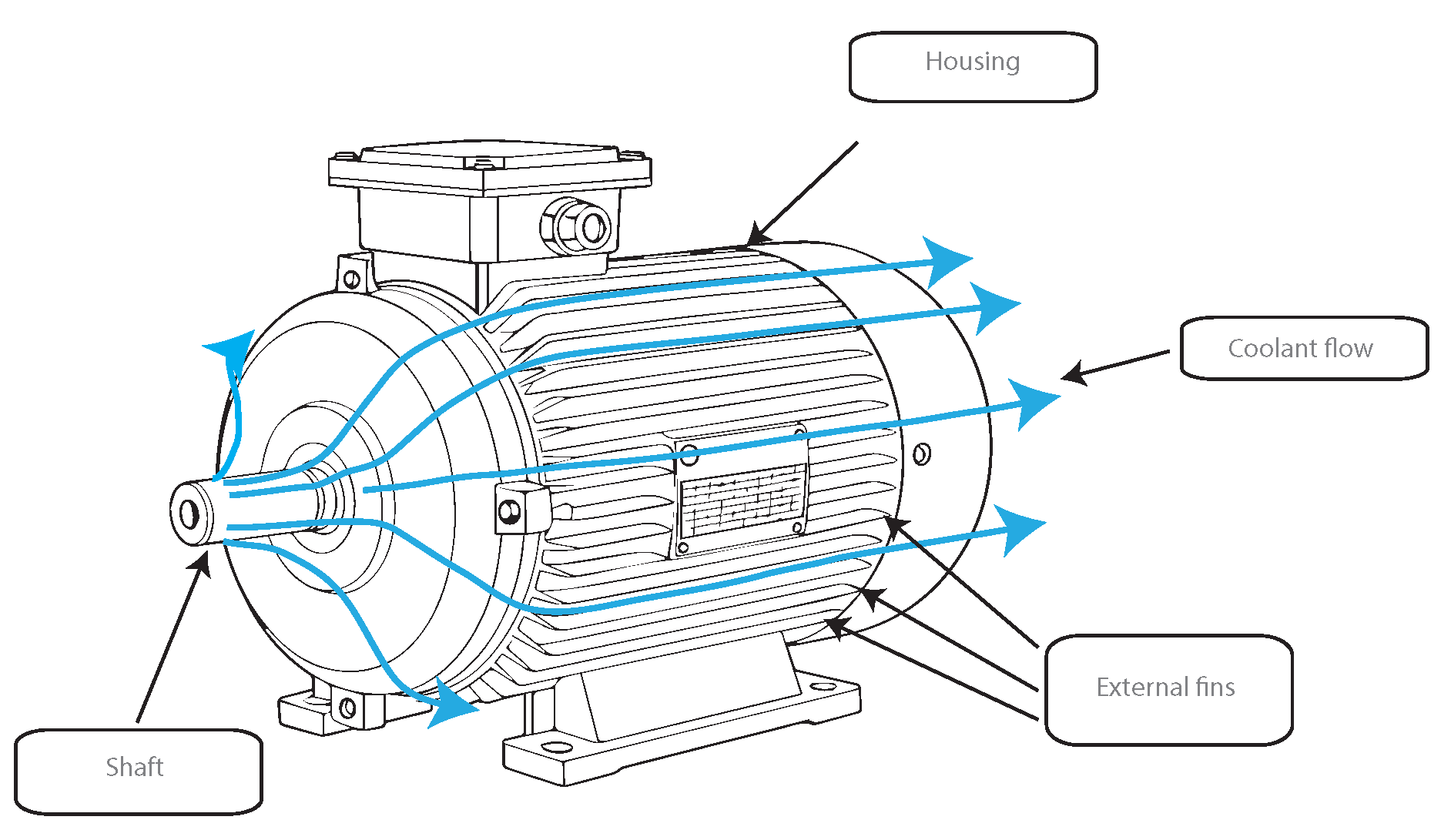
As shown in
Figure 1, the air surrounds the housing. The heat generated by electrical and magnetic losses in elements, such as the rotor and stator windings, is transferred to the housing by conduction; the air in contact absorbs the heat by convection, and the additional fan that has the exchange of hot air to the outside by cold air to the inside, repeating this cycle by the state of operation of the engine.The scarce attention in the literature to the impact of rotor rotation, duct geometry, and environmental confinement indicates that there are still important gaps in their characterization. In summary, air cooling should be considered a complementary solution or applicable only in low-thermal-demand scenarios, and it not a viable option for the design of advanced traction PMSM systems.
2.2. Water Jacket Cooling
Water jacket cooling technology is commonly applied in PMSMs due to their high thermal loads. This method involves the integration of external cavities or jackets, typically surrounding the stator. It commonly involves a volume between the water jacket and housing, through which a cooling fluid circulates to dissipate the heat generated by the motor. In some cases, the water jacket is integrated with the housing with spiral shape on the outer diameter [
21].
This cooling approach relies on forced convection between the channel walls and the circulating fluid. The heat generated by the stator windings inside the motor is conducted to the housing, and the coolant then absorbs and removes this heat as it flows continuously through the system.
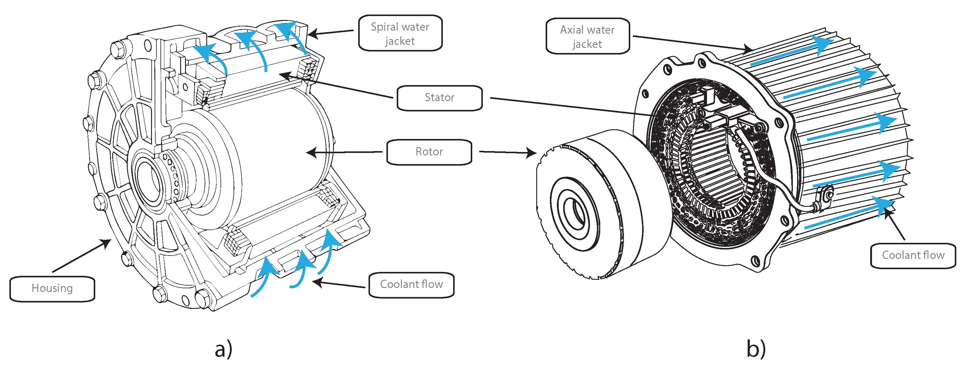
Figure 2 illustrates this process and shows two typical configurations.
In
Figure 2a, the motor is equipped with a spiral water jacket, which wraps around the housing and allows for a longer flow path and increased heat transfer surface.
In
Figure 2b, an axial water jacket design is used, where the coolant flows along the length of the housing, offering efficient directional cooling and simpler implementation.
As the coolant absorbs heat, it is transported to a radiator, where it is cooled and recirculated, maintaining thermal stability during motor operation [
22].
According to the study by [
23], experimental trials with axial jackets achieved a 13% temperature reduction and a system efficiency of 97%. This technology typically yields HTC values between 500 and 1000 [W/m
2·K], outperforming air cooling systems, which generally see thermal reductions between 10 °C and 40 °C. Regular coolant flow rates are in the range of 0.01 to 0.03 kg/s, although actual performance may vary depending on specific test conditions and configurations. Ref. [
21] optimized the system considering the Reynolds number and showed that a configuration with six channels and 12 L/min flow rate can reduce the winding temperature by 6.5 °C and decrease the pressure drop by more than 70% compared to traditional designs.
In a complementary manner, Ref. [
24], through a multiphysics analysis coupled with design of experiments, showed that the tangential arrangement of channels achieves heat transfer coefficients higher than 1800 W/m
2·K, being more efficient than the axial design under continuous load conditions. Likewise, Ref. [
22] highlighted that, compared to methods such as spray cooling or oil cooling, the water jacket offers greater thermal stability without affecting the electromagnetic integrity of the motor. Ref. [
25] proposed a zoned cooling architecture, which achieved differential thermal reduction between the stator and the end of the winding, resolving a common weakness in previous designs. On the other hand, Ref. [
26] highlighted that water-jacketed systems not only allow for efficient thermal management, but they also the integrate infrared monitoring systems for bearing failures, without affecting the thermal uniformity of the assembly. When properly optimized, water jacket cooling offers a robust, scalable, and reliable solution for medium- and high-power PMSM motors.
2.3. Shaft Cooling
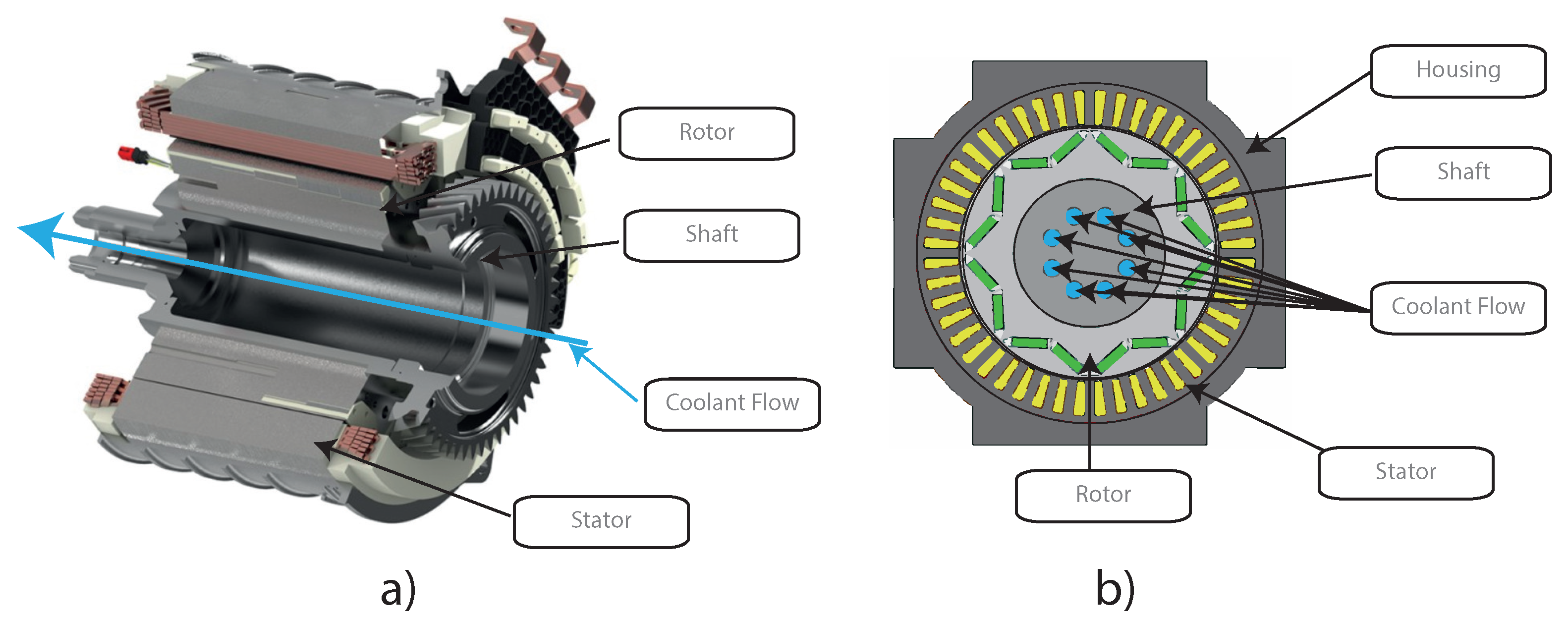
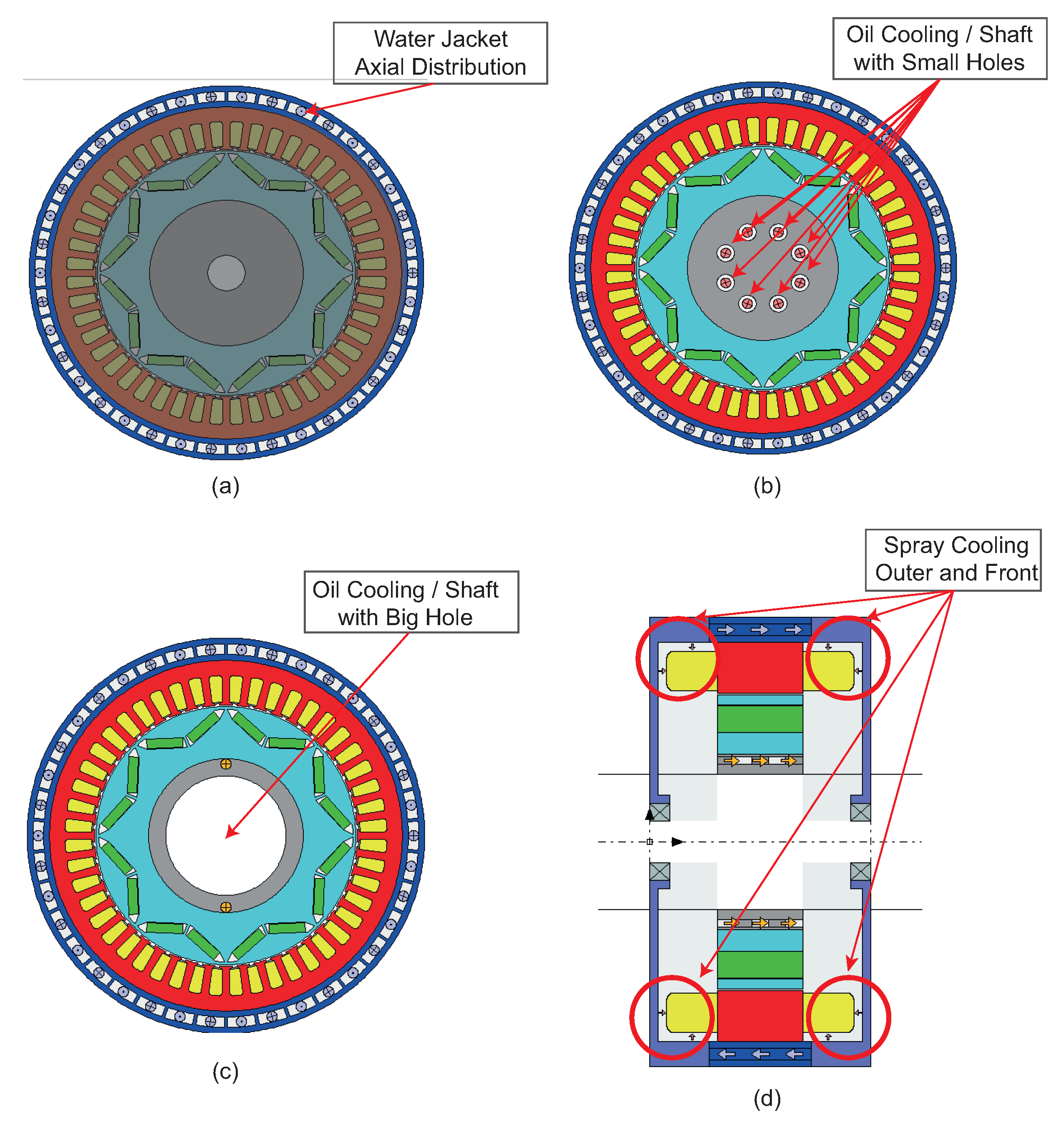
This system operates by designing internal cooling ducts within the rotor shaft, as illustrated in
Figure 3. These ducts allow a coolant to enter the shaft and flow through its internal channels, dissipating the heat generated via convection and transporting it out of the motor to a heat exchanger. This strategy is particularly effective for cooling the rotor, which houses embedded permanent magnets and is typically difficult to cool externally. This is especially relevant in PMSMs, which exhibit high power density and consequently generate significant heat [
27].
In
Figure 3a, the image shows a hollow shaft configuration, where the coolant flows longitudinally through the center of the shaft, efficiently removing heat from the rotor’s core. In contrast,
Figure 3b presents a solid shaft with multiple radial holes that guide the coolant through specific channels toward the center, distributing it across the internal rotor structure and improving heat extraction around the magnets.
Although studies on this cooling technology are still limited, Ref. [
27] reported that implementing hollow shaft cooling reduced rotor magnet temperatures to 32 °C and improved high-speed power output by 4–16%. Furthermore, the HTC for this system ranges from 600 to 1200 W/m
2·K, which represents a significant improvement compared to traditional water jacket systems. Overall, this method achieves a general motor temperature reduction of 30–40 °C, making it a promising approach for high-performance applications.
The study of [
28] performed an experimental comparison between different shaft oil cooling configurations, demonstrating a 15% reduction in rotor temperature and a significant improvement in thermal stability under dynamic transients, while in [
6], in their review of thermal techniques for increasing power density in electric machines, their work examined position shaft cooling as an emerging technique for applications, where they found that rotor heat cannot be efficiently evacuated by indirect methods. Overall this cooling system offers substantial benefits in terms of thermal performance and system energy efficiency, particularly in applications where rotor heat dissipation is critical, but its industrial adoption will require more standardized solutions and long-term durability testing.
2.4. Oil Spray Cooling
Oil spray cooling is considered one of the most advanced thermal management technologies for electric motors, as it uses precision injectors to spray dielectric oil directly onto high-loss areas such as the winding ends, stator windings, and, in some configurations, the rotor. This method is extremely effective due to its ability to deliver localized and directional cooling, significantly reducing thermal hotspots and enhancing overall heat dissipation capacity [
29,
30].
The working principle is based on intensive forced convection, where a system of strategically positioned nozzles injects oil under pressure onto targeted hot regions. Upon impact, the oil forms a thin thermal interface film that rapidly absorbs heat. The heated oil is then collected, directed toward a cooling radiator, and recirculated to sustain the thermal management cycle throughout motor operation [
31].
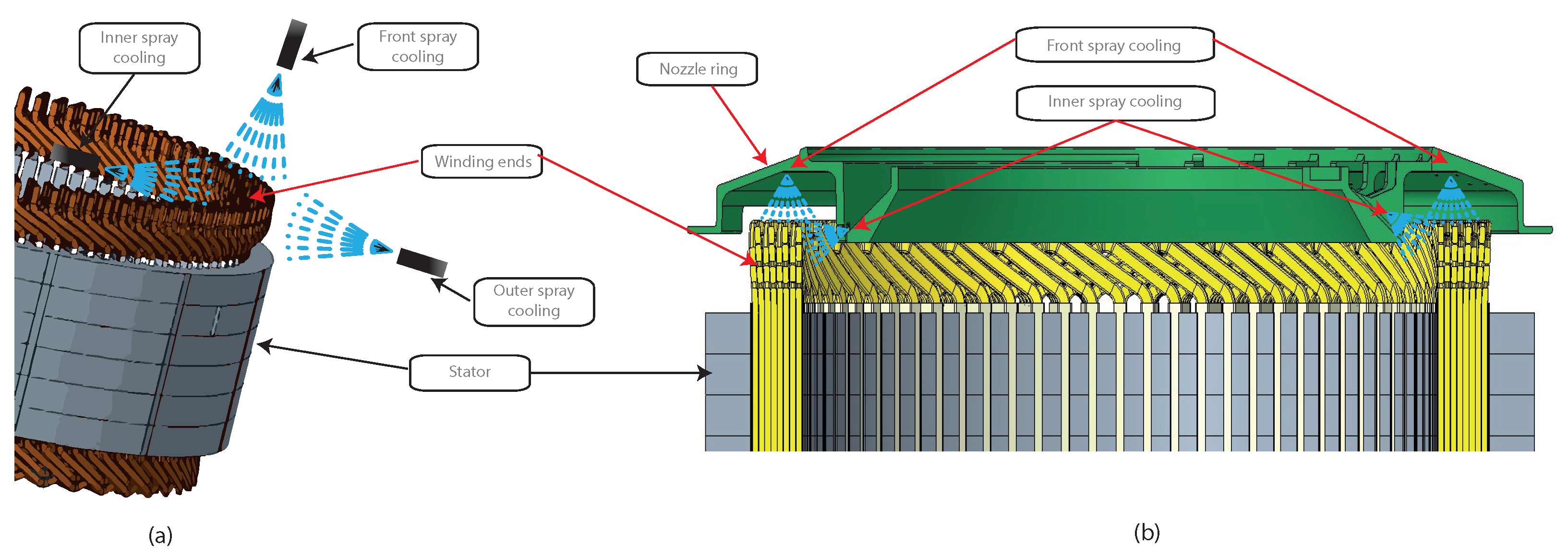
Figure 4 illustrates this concept in detail.
Figure 4a shows the localized injection strategy, highlighting three key oil spray directions:
Inner spray cooling: directed at the inner slots and base of the stator windings.
Outer spray cooling: targeting the external stator winding surfaces.
Front spray cooling: cooling the frontal and upper surfaces of the stator winding coils.
To complement this configuration,
Figure 4b presents a more integrated solution, where a specially designed nozzle ring distributes oil radially across multiple outlet holes. This component enables simultaneous inner and front spray cooling, ensuring broader oil coverage over the winding ends. The nozzle ring itself is mounted near the winding tips and is engineered to conform to the available geometric space within the motor, allowing design flexibility according to specific thermal needs and packaging constraints.
In some motor designs, water jackets may also include internal spray-assisted channels that enhance wetting on the outer housing [
14]. However, oil spray systems provide superior overall coverage, as the sprayed oil, combined with rotor rotation and structural tolerances, spreads over internal surfaces, allowing convective cooling not only of the stator but also the rotor, including magnetized areas that are typically difficult to cool with standard water jackets.
Ha et al. [
32] demonstrated that targeted oil injection at the winding ends reduced hotspot temperatures by up to 30 °C compared to passive cooling systems. Similarly, Davin et al. [
29] reported that multinozzle oil spray cooling achieved heat dissipation rates 2.5 times higher than forced air cooling. The effective HTC for oil spray systems range from 800 to 1500 W/m
2·K, enabling 20–40 °C reductions in critical thermal zones and maintaining optimal motor temperatures between 60 and 80 °C. Another study [
31] showed how oil temperature, flow, and oil level height affect both film formation and air–oil mixing phenomena, with direct implications on decreasing the heat transfer coefficient due to unwanted turbulence effect. Maddumage et al. [
33] complement this view with CFD simulations that demonstrate that impingent jetting oriented to specific zones of the winding locally improves the heat transfer coefficient, making it possible to reduce the critical temperature zones by more than 12 °C.
However, these thermal benefits must be weighed against challenges such as the need for precision nozzles, splash management, potential leakage, and increased mechanical complexity. Despite this, the technical literature shows an emerging consensus: oil spray cooling is currently one of the most effective strategies for high-power-density applications, especially when combined with fluid–thermal simulation and an optimized injection architecture from the design stage.
2.5. Direct Injected Slot Cooling
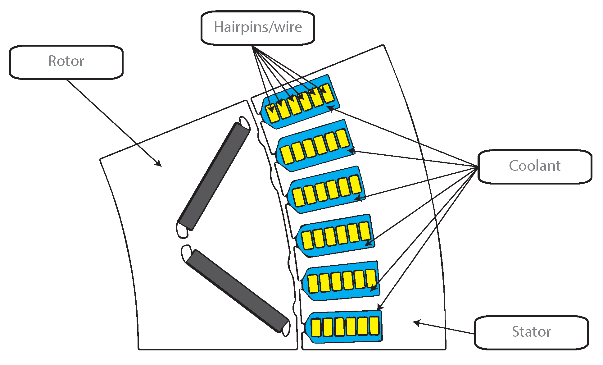
The Direct Slot Cooling (DSC) method has emerged as one of the most promising strategies for improving thermal management in electric traction motors. Unlike traditional water jacket or spray cooling systems, DSC allows the coolant to directly contact the windings within the stator slots, significantly reducing thermal resistance and enhancing heat dissipation. This approach is especially advantageous under high-current-density conditions (>70 A/mm
2), where rapid heat removal is critical to avoid insulation degradation or demagnetization of permanent magnets [
23,
34]. The implementation of DSC not only maintains winding temperatures below 90 °C under harsh driving conditions but also contributes to higher motor performance and extended operational life.
Figure 5 illustrates the working principle of the DSC system. The stator slots are filled with hairpin or wire windings and surrounded by coolant channels that ensure direct contact with the copper conductors. This configuration enables efficient heat extraction from the most thermally stressed regions. As described by Park et al. [
23], the DSC setup typically includes a silicon sealant that isolates the coolant within the slot, allowing precise flow control and maximizing the surface area in contact with the winding. Additionally, the compact integration of coolant paths directly into the stator slots eliminates the need for external jackets, resulting in a more space-efficient and lightweight motor design.
On the other hand, Refs. [
35,
36,
37] highlight that the geometrical design of internal channels, electromagnetic compatibility, and stator thermal management are critical aspects in DSC implementation, especially in aeronautical applications where weight and reliability are key constraints. In their quantitative evaluation, Konda et al. [
37] conclude that the direct slot method offers one of the best ratios between cooling capacity and power density, although it requires complex structural integration that must be addressed from the system design phase. While multiphysics simulations and recent experimental studies support the superior thermal performance of DSC, the authors agree that the biggest challenge remains its integration without compromising the mechanical integrity of the stator or significantly increasing system complexity. In summary, injected slot cooling has a high potential to become a mainstream solution for the next generation of high-performance PMSM motors, especially if combined with additive manufacturing techniques or hybrid integration with conventional methods.
2.6. Phase Change Material
PCMs have been proposed as a promising passive thermal management solution for electric motors, particularly under intermittent and high-load operations. These materials can absorb large quantities of heat during phase transitions from solid to liquid, effectively stabilizing the temperature of critical motor components without the need for active cooling systems. Liu et al. [
38] introduced a novel cooling strategy by embedding PCM directly into the stator structure of a three-phase asynchronous motor, achieving a reduction in stator temperatures of up to 2.4 K per cycle. Likewise, Wang et al. [
39] proposed replacing traditional motor housing with paraffin-PCM enclosures in PMSMs, demonstrating a 32.7% increase in effective operating time and significantly reduced thermal peaks under transient working conditions.
The thermal performance of PCM-based cooling systems depends heavily on the selection of material, particularly its melting point, volumetric latent heat, and thermal conductivity. Organic PCMs such as paraffin are widely used due to their chemical stability and cost-effectiveness, although their low thermal conductivity (0.21 W/m·K) limits their cooling speed, making them more suitable for applications requiring rapid heat absorption [
38]. Shrivatsaan et al. [
40] emphasize the role of PCMs as a part of modern electric motor design strategies, especially when combined with lightweight structural materials, to enhance both energy efficiency and thermal stability.
Mao et al. [
41] proposed the use of phase change materials as thermal protection in pulsed electrical machines, concluding that PCMs effectively retard thermal rise in sudden load events, extending the operating window without risk of overheating. In a more recent hybrid approach, Yousefi et al. [
42] integrated a metal foam heatsink with PCMs and a thermoelectric generator, which not only improved thermal storage capacity but also allowed some of the waste heat to be recovered as useful electrical energy.
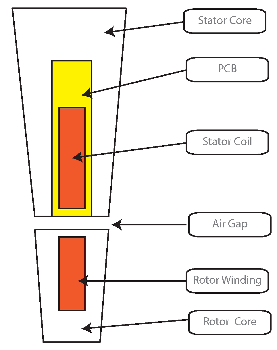
Figure 6 illustrates a typical configuration of a PCM-cooled electric motor. The stator coil, a major heat source, is surrounded by PCM material embedded in the stator core, allowing direct absorption of heat during operation. The air gap separates the stator and the rotor, which also contains windings and core materials. This arrangement maximizes thermal coupling between the hotspots and the PCM, enabling effective heat transfer during both transient and steady-state motor operation.
When selecting PCMs for thermal management in electric motors, it is essential that the materials exhibit high latent heat capacity to efficiently store and release thermal energy during phase transitions. Additionally, they should have a melting temperature that aligns with the operating temperature of the motor components to ensure effective thermal regulation. Good chemical compatibility with metals, low corrosiveness, long-term thermal cycling stability, and sufficient thermal conductivity, either inherently or enhanced through additives, are also critical. Finally, the materials should be safe, economically viable, and suitable for the mechanical and volumetric constraints of the motor’s design. An overview of suitable PCM candidates and their properties is provided in
Table 1 [
43]. Taken together, these studies confirm that PCM represents an innovative solution for scenarios of high thermal demand or without access to active cooling, although its widespread adoption will require standardization in materials, intelligent thermal control, and validation in real vehicle operating environments.
PCM cooling systems are excellent for absorbing short and isolated heat generation peaks; unfortunately, they are not good for rapid or frequent cyclical loads, since their capacity depends on the regeneration time. Therefore, if the cyclic load period is shorter than the regeneration time, systems using PCM may present some deficiencies. Also, they can become saturated if the thermal load is faster than the heat rejection process; its response becomes difficult to control in dynamic applications, as required by car electric motors. Some strategies can be implemented to cover these shortcomings of systems using PCMs, such as hybrid systems combining PCMs with liquid cooling circuits, but this makes the cooling system complex, expensive, and impractical.
The practical application of phase change materials (PCMs) in electric motor systems, especially in proximity to rotating components, presents several critical engineering challenges that must be addressed to ensure system reliability and efficiency.The use of PCMs near the rotor can induce dynamic unbalance due to mass redistribution during the solid-to-liquid phase transition, which alters rotor symmetry and can generate mechanical vibrations at high speeds. This effect has been highlighted in recent studies, such as Wang et al. [
44] and Ding et al. [
45], on rotor unbalance and vibrations in PMSM motors, where even small asymmetries can cause significant dynamic stresses and reduce bearing life.
The volumetric expansion of PCMs during melting typically ranging from 10% to 15% can generate significant internal pressure within encapsulating shells. If this pressure exceeds the yield strength of the shell material, plastic deformation or mechanical failure may ensue, compromising containment integrity [
46]. Approaches such as incorporating internal voids, employing flexible metal shells, or using sacrificial layers have been demonstrated to buffer expansion and prevent rupture [
47]. A recent comprehensive review highlights the importance of strategies like elastic containment, adaptable shell materials, and controlled void space to mitigate cyclic mechanical stress over repeated phase-change cycles [
48].
The low thermal conductivity of many PCMs (paraffin waxes, ≈0.2 W/m·K) limits the ability to absorb and release heat rapidly, particularly under conditions of intense thermal transients. The need to improve thermal performance through the use of additives such as expanded graphite or metallic foams is common [
49]. These challenges reflect the need for a multidisciplinary approach combining thermal, mechanical, and materials engineering in order to fully exploit the benefits of using PCMs in thermal management of electrical machines.
2.7. Overcurrent Control Strategies in PMSMs
Recent advances have focused on advanced control strategies to limit overcurrents in PMSMs, with the objective of reducing thermal stress and avoiding motor damage. These strategies are typically implemented within the Power Electronic Unit (PEU), which serves as the interface between the power source and the motor, managing current flow, switching operations, and protection mechanisms. These recent advances highlight the importance of integrating current limiting mechanisms with thermal models. Dai et al. [
50] proposed a continuous non-singular terminal sliding mode control with critical current restraint based on a control barrier function, which ensures that the current is maintained within safe limits during transient and stationary conditions. This method provides improved robustness and fast convergence while directly considering current constraints in the control law. Similarly, Liu et al. [
51] introduced an equivalent sliding mode controller without a cascade structure based on an improved extended state observer, which helps to improve the disturbance rejection and tracking performance under varying load conditions. Both approaches contribute to the suppression of overcurrent-induced overheating, which is crucial for thermal management and motor reliability. In this study, the thermal effects of overcurrent are taken into account by coupling electromagnetic simulations with thermal models, allowing the evaluation of localized temperature rise in fault or overload situations.
2.8. Efficiency, Cost, and Techical Feasibility
Cooling technologies for electric motors vary significantly in performance, with liquid-based methods generally offering superior thermal control compared to air-based systems. Water jackets, shaft cooling, and oil spray configurations can manage higher heat loads and maintain more stable temperatures, which enhances motor efficiency and power output. While air cooling is simpler, it often struggles under continuous or high-load conditions, making advanced methods more suitable for demanding applications.
In terms of cost, air cooling is the most economical due to its minimal component requirements and ease of implementation. It is ideal for low-cost systems or applications with moderate thermal demands. Liquid cooling systems, on the other hand, involve higher initial investment due to added components and system complexity, but they offer greater long-term performance and reliability, making them cost-effective in high-performance or mission-critical environments.
From a feasibility standpoint, air cooling is the easiest to integrate and widely compatible across different motor designs. Water jackets represent a practical compromise, offering good performance with manageable design complexity. More advanced techniques like shaft cooling and oil spray require careful engineering, including fluid management, sealing, and structural considerations, which can limit their application to specialized or high-performance systems.
Table 2 summarizes the most relevant cooling technologies applied to PMSMs in electric vehicle applications. The table includes the findings and reported thermal performance for each method, which are grouped by technology type such as air cooling, water jacket, oil spray, shaft cooling, direct sloot cooling, and PCM.
3. Methodology
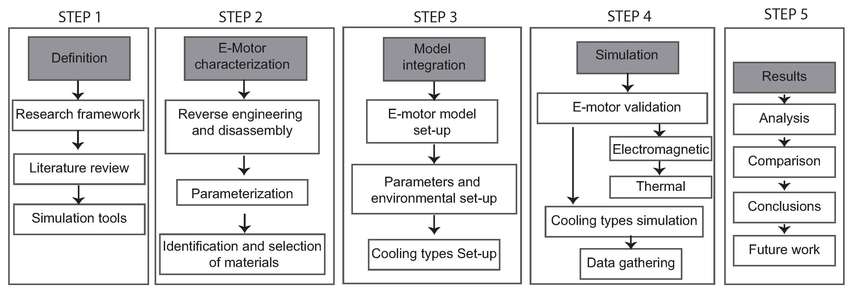
The methodology illustrated in the
Figure 7 is used in this research, and it begins with the definition of the research framework, including a literature review and the selection of simulation tools. In the second step, a commercial electric motor is characterized through reverse engineering and disassembly, followed by parameterization and material identification. Step three focuses on model integration, where the motor model is set up along with the definition of environmental conditions and cooling types. In step four, the motor is validated electromagnetically and thermally, and different cooling methods are simulated, with the data gathered for analysis. Finally, in step five, the results are analyzed and compared on the basis of the space required and a summary of the criteria for selecting the type of refrigeration to draw conclusions and propose future work. This methodology supports a state-of-the-art review by combining theoretical research with practical simulation of various cooling strategies in a commercial electric motor, enabling a comprehensive evaluation of thermal performance.
3.1. Technical Characteristics and Specifications
The e-motor is the key piece of the research, since it is the element that will be simulated and performed all the energy efficiency tests; this motor is electric and is integrated into the hybrid transaxle.
Table 3 shows the technical specifications from original manuals obtained from Toyota Motor Corporation, where the starting information for this research was obtained.
3.2. Tools and Software
The study developed by [
6] states that (Ansys MotorCAD
®) is a friendly software that evaluates a series of configurations or topologies in an extensive range of motors in all types of operation to optimize designs in terms of performance and efficiency; it has integrated modules such as electromagnetic design, thermal design (Therm), mechanical design (Mech), and a laboratory mode (lab) that helped us to perform multiphysics calculations quickly and repetitively, thus obtaining a final design in less time.
Compared to other ways of evaluating thermal models, MotorCAD
® predicts the temperature of vital motor elements such as the stator with a deviation of less than 5% and develops 40 times shorter simulation times [
65]. By integrating thermal and electromagnetic analysis, an improvement is achieved with an efficiency increase of 4.2% efficiency on average.
Technologies such as CFD and FEA were included in the program in a simplified and optimized way, thus speeding up its design without losing accuracy. According to [
68] a better result of +12%, torque density was achieved by optimizing the motor geometry with the use of fast FEA in MotorCAD
®, while [
65] evaluation performed at maximum winding temperature with MotorCAD
® thermal model obtained an error of less than 4.5% compared to Ansys Fluent CFD 3D, but the computation was 30 times lower.
The empirical correlations are equations derived from experimental data or CFD simulations that are part of the program, especially for the thermal model work; in this way, it is possible to estimate how the HTC is distributed throughout the electric motor, thanks to this accurate thermal analysis being obtained without having the need to perform full CFD simulations, which accelerates the design analysis. The good calibration of thermal correlations in MotorCAD
® made it possible to efficiently predict the HTC in spray cooling cooled zones, with an accuracy of 92% compared to 3D CFD simulations [
58].
3.3. Reverse Engineering Procedures
For the electric motor simulation, it was necessary to obtain geometrical measurements of each component using precision measuring tools such as a digital caliper and a micrometer. The focus was placed on three key elements: the rotor, where the length, internal diameter, and external diameter were measured; the stator, including its lengths and diameters; and the shaft and winding diameters. These measurements were collected to support the analysis of the motor’s thermal efficiency and to validate the data against the manufacturer’s specifications.
Table 4 shows a summary of the geometrical specifications from direct measurements of the original electric motor where the starting information for this investigation was obtained.
3.3.1. Original Cooling Specifications
The cooling system in this aluminum casing is based on internal chambers or machined galleries that absorb heat generated, this cooling is liquid type (mixture of water and ethylene glycol). The fluid enters through an external connection to the chambers, circulates through the hot zones, extracts the heat, and is directed to a heat exchanger. According to the observation of the casing configuration, it was estimated that this engine was cooled 65% of its critical volume.
3.3.2. Materials Considered for the Analysis
Examining a series of materials of which each of the elements were composed and considered for later validation with the original motor, the stator and the rotor were built with a material M350-50A, which is characterized for being a silicon electrical steel type material; it was used in magnetic cores of electric motors, transformers, and generators. The windings were the series of copper coils arranged in slots of the magnetic core, and these were composed of copper material (pure). Finally, the magnet was composed of N30UH, a specific type of neodymium magnet (NdFeB) of high power; see
Table 5 for each component and material defined.
3.4. Software Configuration
The software setup in MotorCAD
® began with the integration of detailed physical measurements obtained from the real electric motor, including dimensions of the rotor, stator, shaft, and winding assemblies. These parameters were manually input into the software to replicate the actual geometry of the motor as closely as possible. In addition, the motor’s nominal operating conditions were defined to reflect realistic usage scenarios. Multiple cooling configurations were set up in the simulation environment according to
Figure 8.
The following list presents the single and combined cooling strategies evaluated during the simulation campaign:
No Cooling;
Air Cooling;
Axial Water Jacket Cooling;
Water Jacket + Shaft Oil Cooling (1 Big Center Hole);
Water Jacket + Shaft Oil Cooling (8 Small Holes);
Water Jacket + Oil Cooling (1 Big Center Hole) + External Spray;
Water Jacket + Oil Cooling (1 Big Center Hole) + External + Front Spray.
3.5. Test Conditions for Simulations
Table 6 summarizes the thermal and fluid boundary conditions applied to the various cooling strategies evaluated in this study. These include configurations ranging from natural convection (no cooling) to forced air cooling, water jackets, as well as combinations of oil crossing to the shaft and spray cooling. The inlet temperature, volumetric flow rate, and HTC of the coolant are reported for each case. This information serves as the basis for comparing the thermal performance and effectiveness of each configuration under standardized conditions.
The specific direction and method of coolant circulation in each configuration are described as follows: air cooling is applied through a rear inlet; the axial water jacket drives the coolant from front to rear along the housing channels; oil shaft cooling systems use ATF134 and are injected either through one or eight holes depending on the setup, always from the front side. For enhanced configurations, external spray cooling is applied, and in the most advanced case, both external and frontal sprays are combined to maximize thermal transfer around the stator and rotor regions.
4. Results
4.1. Validation of the Simulation
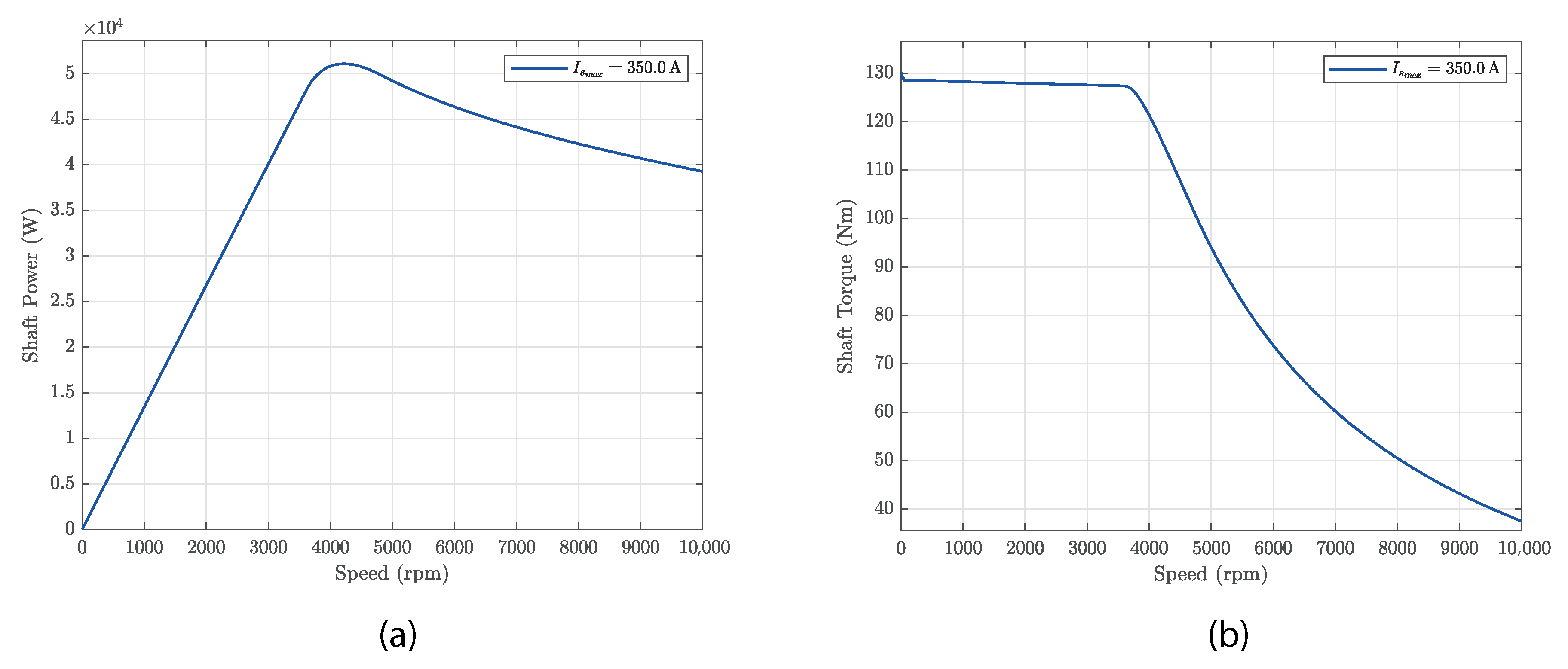
The simulation was validated by comparing the output torque and power curves of our model against nominal specifications of a Toyota MG motor. At a maximum current of 350 A, the model accurately reproduced the expected maximum torque of 130 Nm and a power output of 50 kW, in accordance with the manufacturer’s data [
78,
79]. This correlation confirmed that the integrated geometry, materials, and operational parameters were correctly configured, ensuring the reliability of the simulation results.
Figure 9 illustrates the simulation results of the electric motor under a maximum current of
A. The left plot shows the shaft power as a function of speed, which increased nearly linearly in the low-speed range, reaching a maximum value of approximately 50 kW around 4000 rpm. Beyond this point, power gradually decreased due to the drop in torque. The right plot presents the corresponding shaft torque, which remained constant at 130 Nm in the range of 0–4000 rpm, indicating operation in the constant torque region. As the speed increased beyond this point, the motor entered the field-weakening region, where the torque declined due to the BEMF limitation. This characteristic behavior highlights how torque is prioritized at low speeds and efficiency is favored at medium and high speeds, reflecting the typical dynamics of an PMSM operating under constant current and voltage availability conditions.
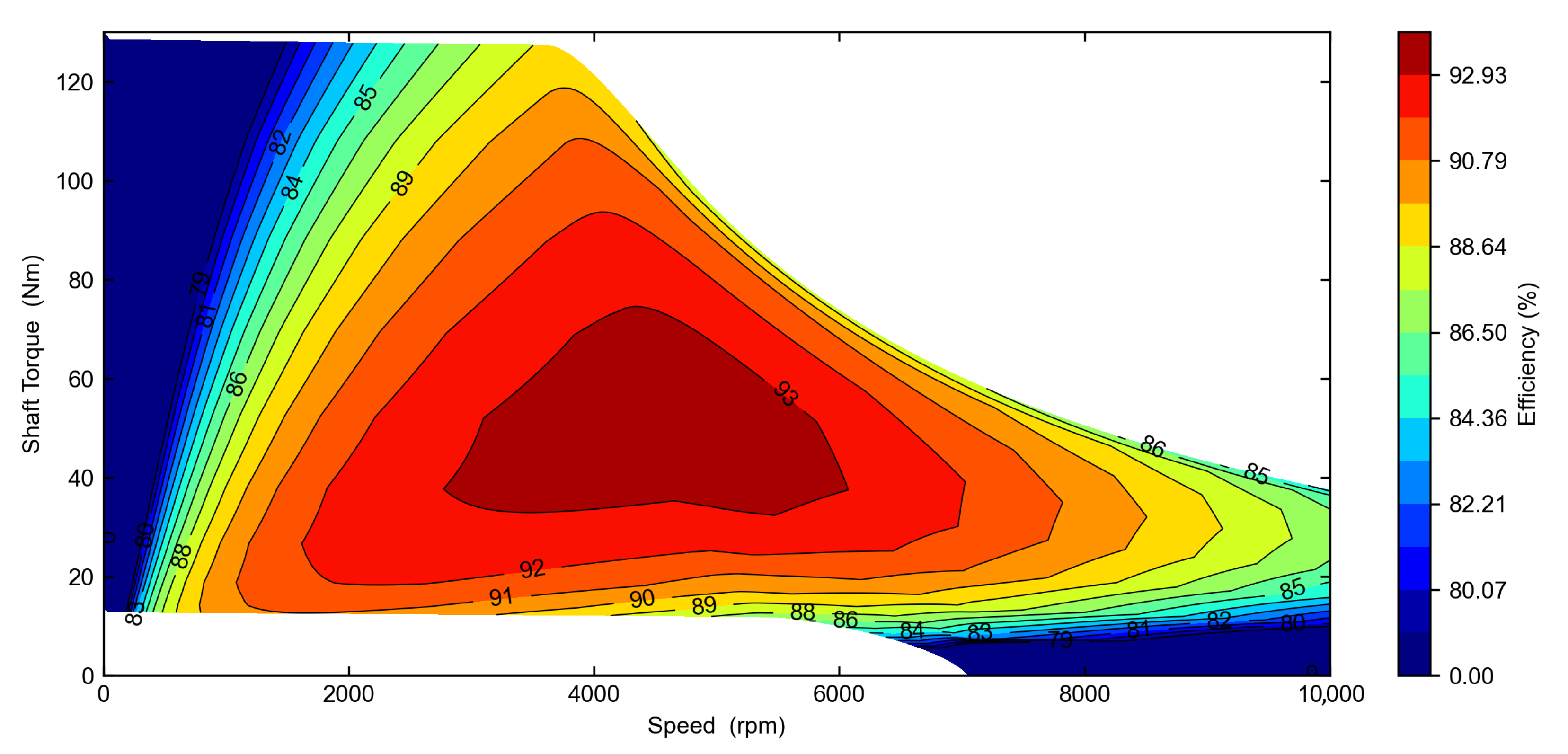
Figure 10 shows the efficiency map of the electric motor as a contour plot, where the efficiency levels are depicted as a function of shaft torque and speed. The highest efficiency region, highlighted in dark red, reached up to 92.9% and was centered around 4000–5000 rpm and 50–70 Nm. This optimal operating zone corresponds to the motor’s peak electrical to mechanical energy conversion performance. The medium to high efficiency area, shown in shades of orange and yellow, extends across a broader operating range between 2500–7000 rpm and 10–100 Nm, making it suitable for continuous-duty operation. In contrast, the low-efficiency regions, illustrated in dark blue, occurred at the speed and torque extremes—below 1000 rpm and above 8000 rpm where switching losses, AC losses, core losses, or field weakening reduce the motor’s overall efficiency.
4.2. Comparative Analysis
This section presents a comparative analysis of the motor’s thermal and electrical performance under various cooling configurations. Key performance indicators were examined as functions of motor speed. These results allowed us to evaluate the effectiveness of each cooling method and identify the optimal configuration for high-demand applications.
4.2.1. Phase Current Behavior vs. Speed Analysis
Motor temperature plays a critical role in defining the actual current delivered during operation. In real-world applications, the PEU dynamically limits the motor current to prevent thermal overload when critical components such as stator windings or rotor magnets approach their maximum allowable temperatures. For this analysis, MotorCAD® was configured with thermal thresholds to replicate the PEU behavior, ensuring that the current reductions reflect realistic thermal protections.
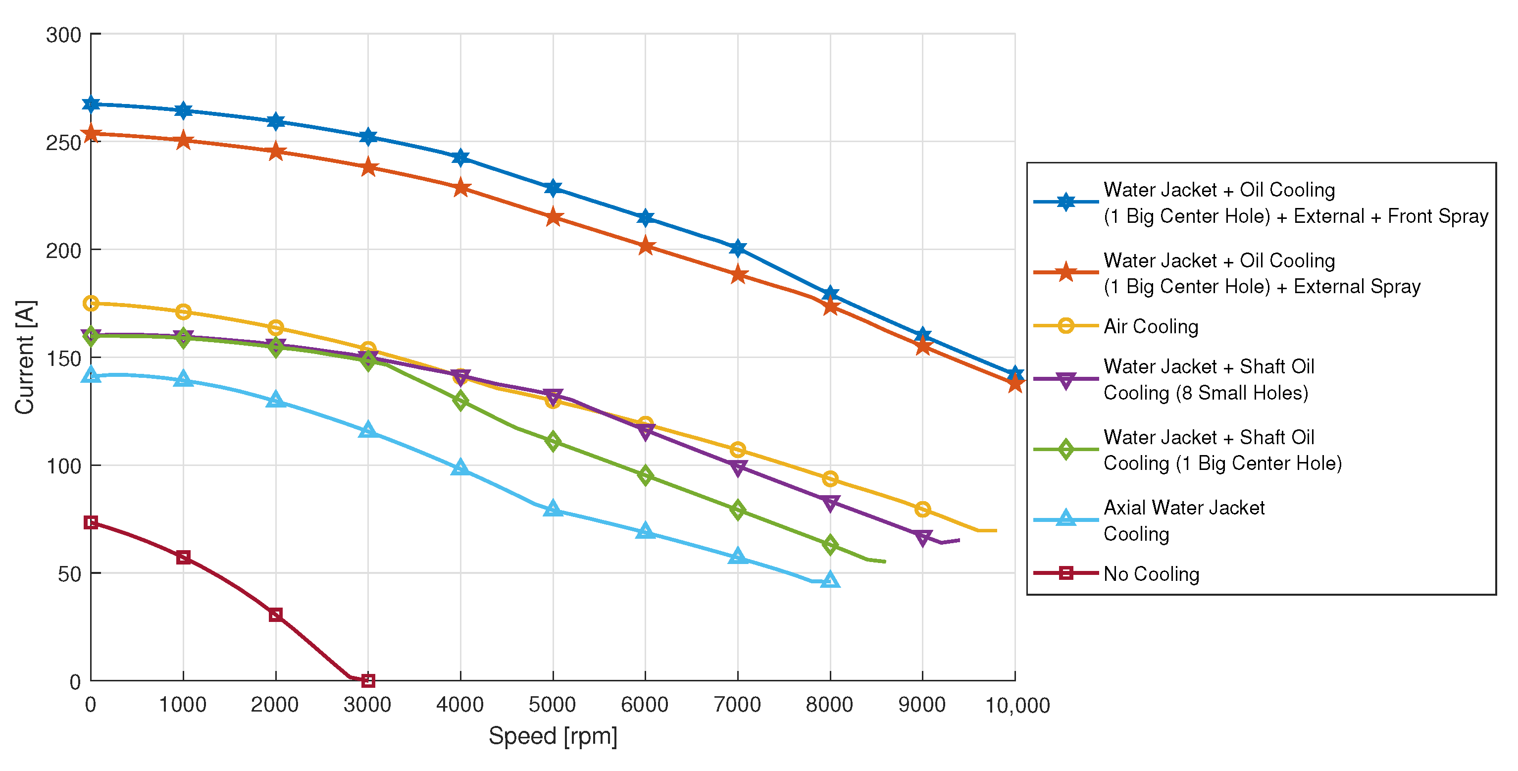
The results in
Figure 11 shows that the motor without cooling quickly reached its thermal limit, restricting operation to about 3000 rpm and 75 A of the current. The axial water jacket improved performance, reaching 8000 rpm at 140 A. Systems combining water jacket and shaft oil cooling, whether using one big center hole or eight small holes, offered higher current capacity (160 A) and extended speed operation, with the eight-hole configuration performing slightly better.
Air cooling achieved moderate performance, supporting 170 A up to nearly 10,000 rpm. The most efficient configurations involved hybrid systems with oil spray. The external spray system allowed over 250 A and operation beyond 10,000 rpm, while adding frontal spray further increased the current delivery to 260 A and maximized the speed range. These findings confirm the thermal advantages of targeted and combined cooling methods.
4.2.2. Magnet Thermal Response
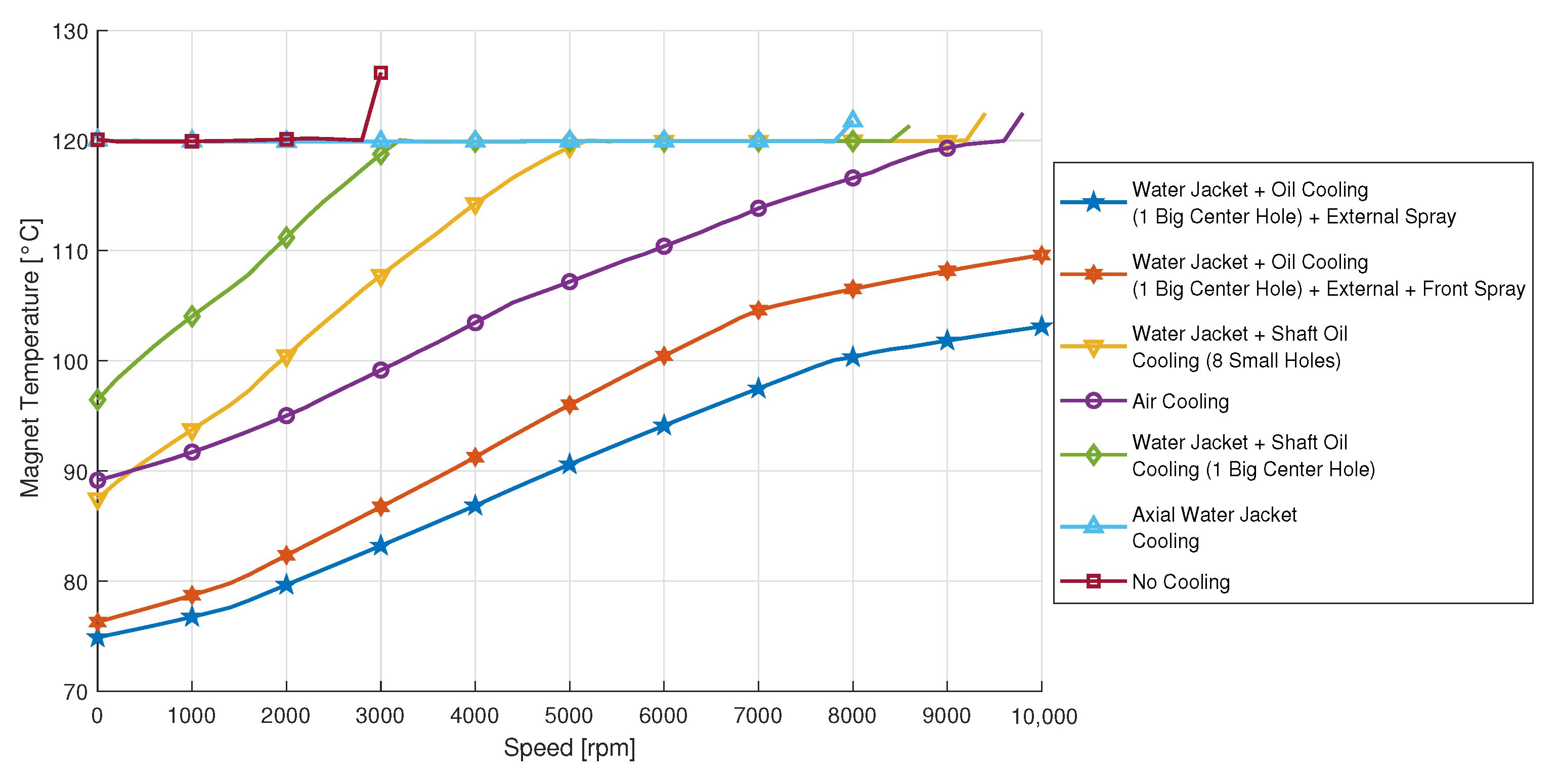
Figure 12 analyzes the temperature of the magnets as a function of the speed in a range of (0 to 10,000 rpm). It can be observed that, at continuous operation, the worst performance corresponded to the motor evaluated without any type of refrigeration, where the magnet temperature was 120 °C in the evaluated section and only reached up to 3000 rpm of its work, followed by the axial water jacket system, where the temperature was a constant 120 °C but reached a higher speed range of 8000 rpm. The combined systems tended to improve the temperature of the motor elements. The water jackets with single-hole shaft cooling started with a temperature of 98 °C until it stabilized at 120 °C and increased the speed range to 8500 rpm, while the water jackets with shaft cooling by eight holes started the operation with 88 °C, stabilized at 5000 rpm, and reached 120 °C at high speeds.
Similar operation had the test performed with the current peak at 350 A and air cooling system, with the difference being that it only reached 120 °C at 9000 rpm, keeping the motor with better cooling at higher speeds. Finally, the systems that had better results were those that combined axial water jackets, shaft cooling, and front-external spraying, reaching temperatures below 120 °C for more speed and even exceeding 10,000 rpm. We consider these forms as the most efficient and optimal to apply to the motor.
4.2.3. Stator Winding Thermal Response
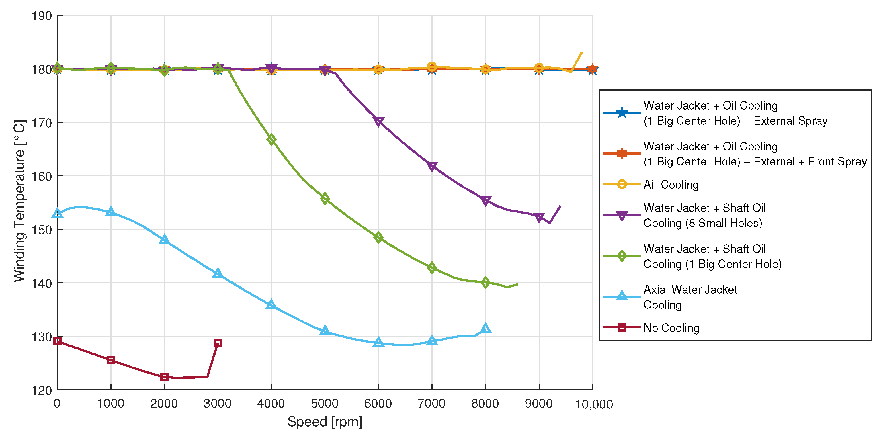
Figure 13 shows the behavior of the winding temperature as a function of speed in a range between (0 to 10,000 rpm). The image shows how the uncooled systems and water jackets have less heat dissipation. So, they are not suitable for motors that need high current consumption and operate at high speed. The systems that combine water jackets and shaft cooling, either with one or eight holes, achieved better results, starting their temperature at 180 °C and reaching higher speeds until reaching values higher than 8000 rpm.
Finally, the systems that combine water jackets, shaft cooling and spraying were the ones that achieved better performance management to maintain the temperature of 180 °C for a much larger range of speed, exceeding 10,000 rpm, which is vital for the operation of these high demand motors. This variable is important, since the stator is the place where the most important Joule losses are concentrated, and therefore, the heat is greater, an efficient cooling system avoids problems regarding the integrity of the winding insulation, and the motor does not overheat and increases the useful life.
4.2.4. Torque Capability Under Thermal Constraints
As shown in
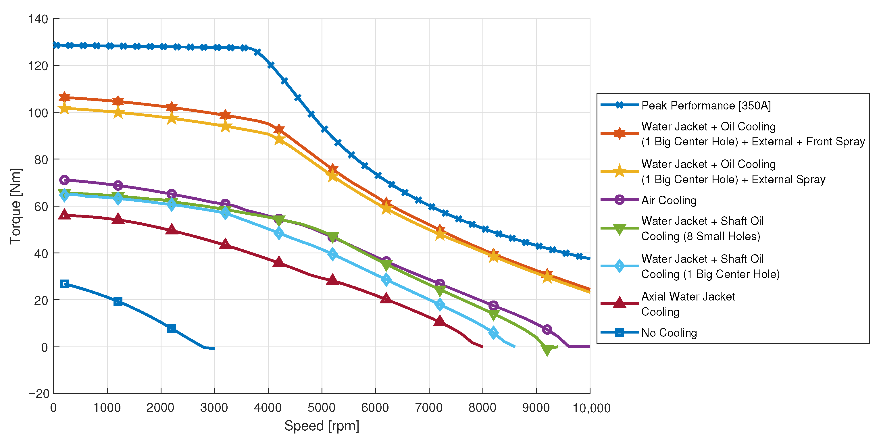
Figure 14, the analysis of maximum torque delivered by the electric motor, in continuous operation under different cooling methods, highlights the essential role of thermal management in torque preservation at low speeds. The “Peak Performance [350A]” operation reached the highest torque value of 130.1 Nm, clearly standing out as the ideal high-load operating condition, since this operating condition was not limited by temperature as the continuous operation condition. Among passive cooling options, “Air Cooling” offered a moderate peak torque of 72.5 Nm, which is significantly higher than the 28.8 Nm delivered under “No Cooling” conditions. This stark contrast reinforces how thermal limitations without cooling severely restrict torque output, particularly at startup or low-speed phases.
Liquid and oil-based cooling methods exhibited a considerable improvement in torque capabilities. “Axial Water Jacket Cooling” increased the available torque to 56.7 Nm, while “Water Jacket + Shaft Oil Cooling” (using one big center hole and eight small holes) further enhanced torque output to 65.8 Nm and 66.6 Nm, respectively. The most efficient configurations were those integrating external oil spray, “Water Jacket + Oil Cooling (1 Big Center Hole) + External Spray” and its extended version with External + Front Spray, achieving 103.2 Nm and 107.8 Nm, respectively. These results confirm that the combination of water jackets with active oil injection significantly improves thermal dissipation, allowing the motor to maintain high torque values.
4.2.5. Power Capability Under Thermal Constraints
As illustrated in
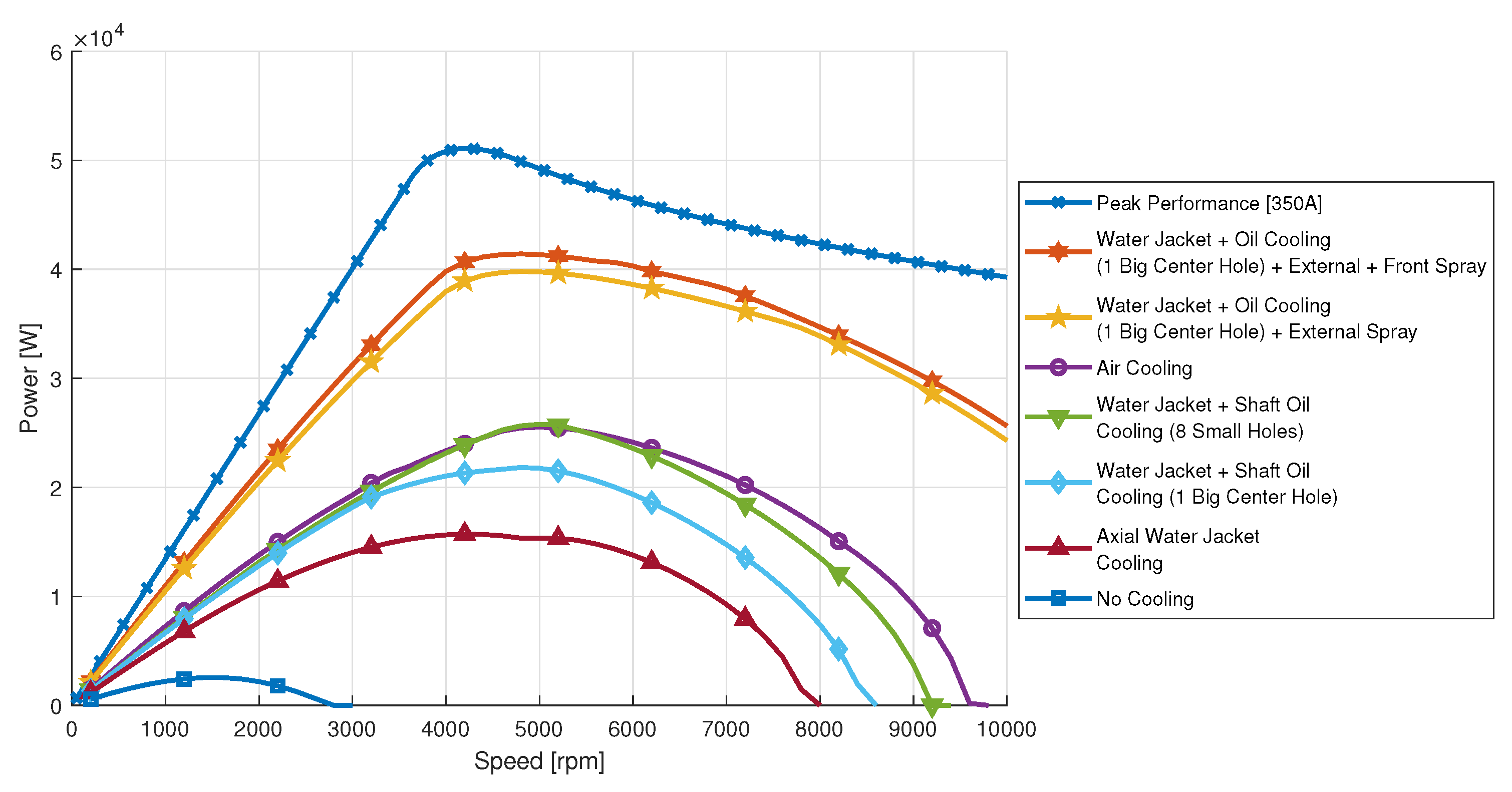
Figure 15, the comparative analysis of power performance across different cooling strategies reveals that the Peak Performance [350A] operation, of course, outperformed the continuous operation condition provided with any cooling system, achieving a maximum power output of 51,086 W at 4200 rpm. Among the conventional cooling methods, Air Cooling demonstrated the highest power capacity at 25,526 W, peaking at 5000 rpm, indicating reasonable thermal management efficiency for lightweight or less demanding applications. In contrast, the No Cooling condition yielded the lowest power output, with just 2553 W at 1600 rpm, clearly highlighting the impact of thermal constraints in the absence of any active or passive dissipation mechanisms.
Liquid-cooled systems, particularly those integrating oil-based enhancements, offer a notable performance advantage. The Axial Water Jacket Cooling configuration provided 15,704 W at 4200 rpm, whereas the addition of Shaft Oil Cooling with a single large center hole raised the peak output to 21,823 W at 4800 rpm. These results underscore the importance of combining convective and conductive cooling mechanisms to enhance motor performance under continuous operation. Further analysis of configurations employing multiple oil spray techniques (e.g., external and frontal spray) is expected to reveal additional improvements in both thermal stability and power delivery, especially at higher speeds and loads.
5. Discussion
5.1. Design Space and Integration Considerations
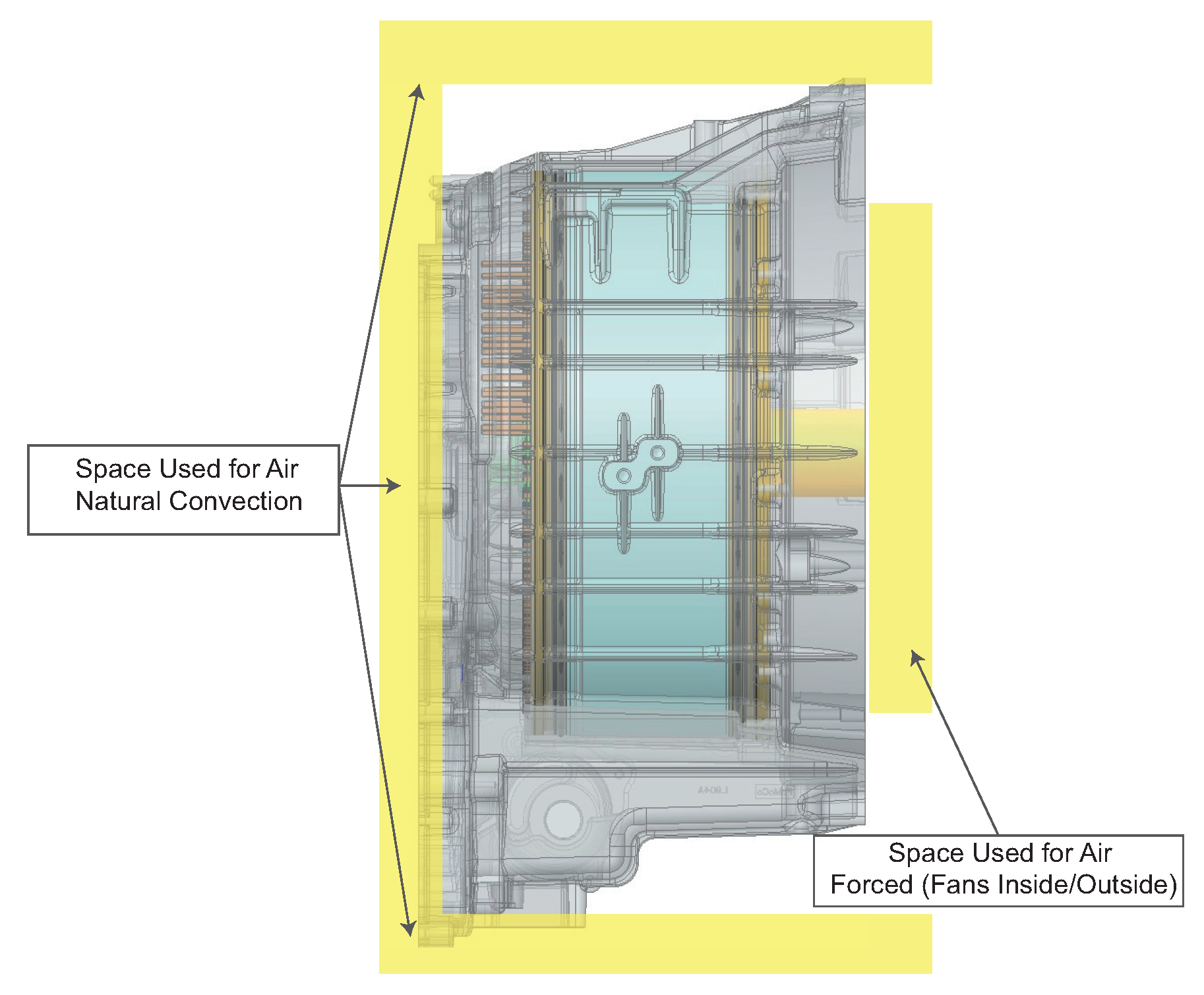
To implement advanced cooling strategies within an electric motor, sufficient internal space must be reserved for additional components. Air cooling strategies, especially natural convection, depend on adequate clearance around the motor to enable upward heat dissipation. To enhance this, external fins should be included on the housing surface to increase convective surface area. For forced air cooling, fans must be carefully distributed internally to push/pull air across stator windings and externally to circulate air across fins or ducts. This approach demands additional design volume and structural accommodations for mounting and powering the fans, as well as ensuring that airflow is not obstructed by adjacent components or vehicle bodywork.
The
Figure 16 shows a semi-transparent view of an electric motor focused on air-based cooling methods. It highlights two distinct zones:
Natural Convection Space: The region surrounding the motor that allows ambient air to flow and dissipate heat through passive convection.
Forced Air Cooling Space: Yellow-shaded paths on the outer perimeter represent areas where fans can be installed inside or outside the housing to direct airflow more aggressively.
To improve cooling efficiency, fins can be integrated onto the motor housing to increase surface area. In the case of forced cooling, fans may be mounted internally (near the stator ends or inside the motor housing) or externally (on the casing or chassis near high thermal zones). Fan placement should ensure uniform airflow and minimize obstruction to electronic components.
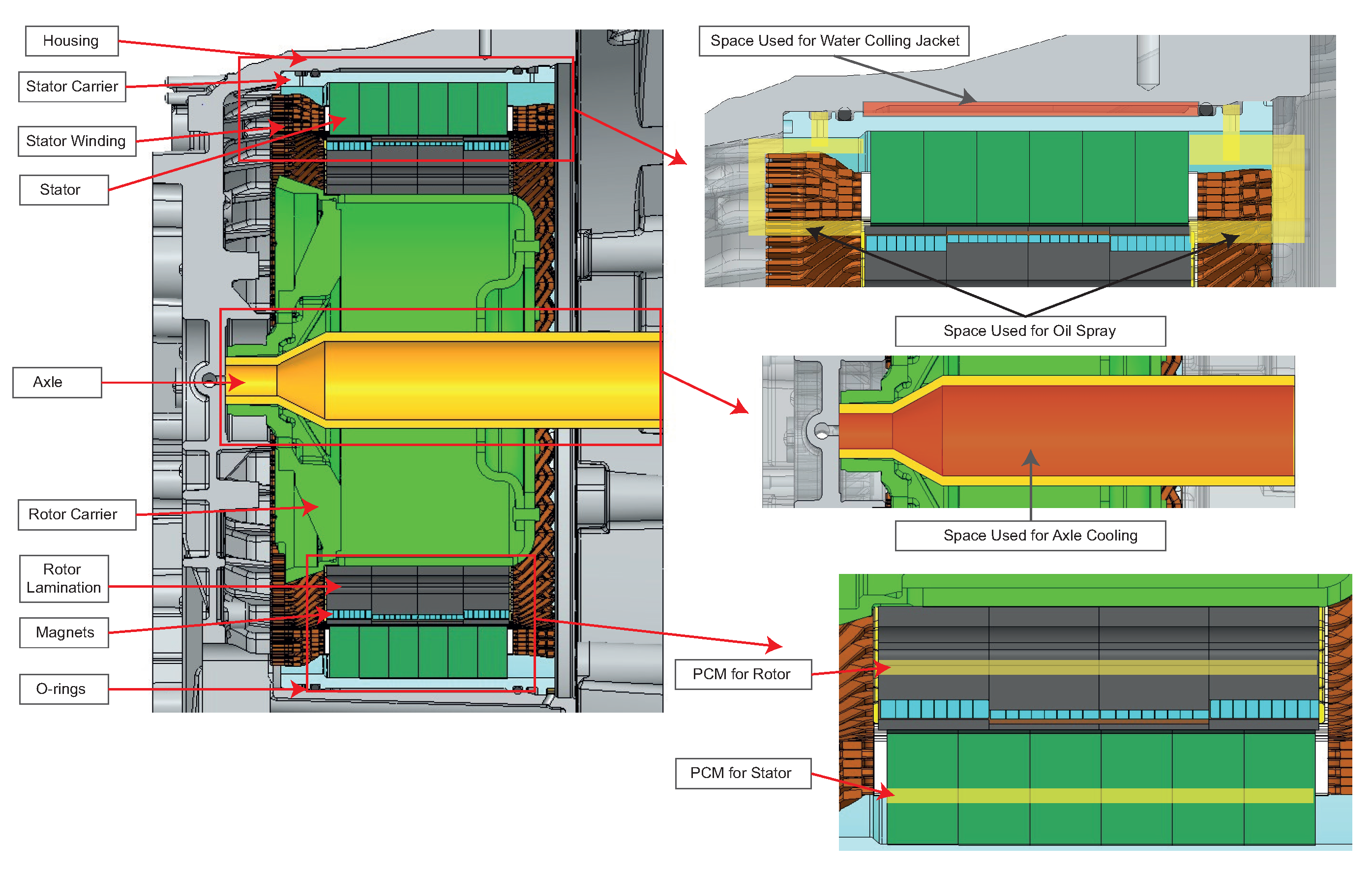
On the other hand, for extra components such as jackets, channels, oil passages, and thermal interface materials, the integration of a water cooling jacket requires sealed pathways surrounding the stator windings and dedicated inlet/outlet ports for coolant circulation. Oil spray cooling demands precise nozzle positioning and flow management channels that directly target critical heat-generating zones. Meanwhile, axle oil cooling necessitates a hollow or segmented shaft capable of safely channeling oil flow without compromising mechanical strength.
Figure 17 illustrates a cross-sectional view of an electric motor with labeled components and the internal spaces allocated for different liquid-based cooling strategies. The following cooling paths are highlighted:
Water Cooling Jacket: Space around the stator, enclosed by the housing, reserved for circulating water or coolant fluid to extract heat from the stator windings.
Oil Spray Cooling: Channels located between the rotor and stator region, which in some designs are formed by additional components attached to the motor housing. These channels help redistribute the dielectric oil directly onto the winding heads and stator teeth, significantly improving localized cooling through direct contact and convection.
Axle Oil Cooling: A hollow central channel inside the shaft that allows oil circulation through the rotor core, effectively extracting heat from the rotating components and improving overall thermal management.
Phase Change Material (PCM): This material is embedded in isolated cavities located in either the rotor or stator, where it undergoes phase transition during high thermal loads. The PCM acts as a thermal buffer, absorbing excess heat and delaying temperature rise. In many applications, it behaves like a thermal fuse, mitigating short-term temperature spikes that occur under transient or peak operating conditions.
Direct Slot Cooling (DSC): A specific stator design is required in which the slots are larger and have reinforced insulation in order to allow direct passage of the cooling fluid to the winding. This configuration facilitates more efficient heat transfer by acting directly on the areas of highest heat generation.
This design reveals the need to dedicate precise internal volumes for embedded cooling channels, which requires adjustments to the rotor carrier, axle geometry, and stator housing design. Integrating these systems also demands robust sealing solutions (e.g., O-rings) to avoid leaks and electromagnetic compatibility considerations.
5.2. Generalized Design Principles
Based on the simulation outcomes and critical review of the literature, five key design principles are identified to guide the selection of cooling strategies in permanent magnet synchronous motors (PMSMs):
For motors exceeding 4 kW/kg in power density, prioritize internal cooling paths, such as direct slot cooling or oil spray, complemented with water jackets for thermal uniformity.
For high-speed applications operating above 12,000 rpm, implement axle oil cooling to protect rotor magnets and bearings from demagnetization and thermal degradation.
When budget constraints are below $20/kW, favor robust and proven water jacket systems using standard aluminum cast housings over complex oil-based or embedded systems.
If the development time is under six months, avoid adopting custom slot-cooled or spray-based architectures and instead opt for mature solutions such as water jackets or forced-air configurations that require minimal integration effort.
For applications in dusty, humid, or corrosive environments, avoid open oil spray systems unless equipped with filters and chemical-resistant seals to ensure reliability and longevity.
These criteria enable early-stage decision making aligned with the specific thermal loads, spatial constraints, cost-performance targets, and environmental conditions of the application. A comparative summary of cooling strategies, including their technical advantages, limitations, and recommended use cases, is presented in
Table 7, which serves as a practical guideline for design engineers during the motor development process.
Each cooling strategy serves specific application niches depending on the motor’s power, operating conditions, and design constraints. Air cooling is suitable for small motors under 10 kW or low-duty applications with tight budgets. Water jackets are ideal for production EVs ranging from 10 to 150 kW with steady-state thermal loads. Oil spray cooling is recommended for high-performance motorsport e-axles or traction systems with localized hotspots. Axle oil cooling benefits high-speed (>12,000 rpm) applications where magnet temperature must be tightly controlled. Direct slot cooling is best suited for premium compact drivetrains requiring high power density, while phase change materials are optimal in lightweight systems with short bursts of thermal stress, such as UAVs or collaborative robotics.
5.3. Power Density and Estimated Development Cost for PMSM
The power density value considered for this work was based on the motor generator of the vehicle model: a Toyota Highlander Hybrid 2010. It is a PMSM motor with a peak power of 50 kW and a weight of 22.88 kg, obtained through actual weights of the motor, resulting in a power density of 2.18 kW/kg. This value represents a realistic technical baseline that is easily verifiable and aligned with the electric motors used in first-generation hybrid vehicles. Furthermore, it allows for establishing a baseline within a credible and measurable technological evolution framework in the automotive industry.
Recent studies support the steady growth of this indicator. Sudha et al. [
80] present a review of 13 high-power-density motor designs for electric vehicles, reporting ranges between 0.3 and 5.0 kW/kg, with configurations such as high power density in the PMSM reaching more than 4 kW/kg. In turn, König et al. [
18] highlight that axial flux motors exceed 5.0 kW/kg in aeronautical and high-performance applications. Likewise, a technical benchmarking study conducted by Drexler et al. [
81] on 48 commercial electric motors used between 2018 and 2023 indicates that the average peak power density in PMSM varies between 2.0 and 3.3 kW/kg, with 3.28 kW/kg being one of the highest recorded. These values position the selected MG reference within a valid and conservative spectrum in terms of evolutionary design.
Regarding the estimated development cost, studies were integrated that consider not only the production volume but also the selection of materials and manufacturing technologies. Liu et al. [
82] present a robust design approach for PMSM motors with soft magnetic composite (SMC) cores, which allow for reducing the production cost by avoiding the use of expensive materials such as NdFeB magnets, incorporating alternatives such as ferrite magnets and molding processes instead of wire-cutting. These types of strategies aim to achieve low-cost motors without significantly compromising electromagnetic performance, especially in medium-power applications such as the one evaluated.
On the other hand, Refs. [
81,
83] report, through comparative analysis and benchmarking studies, that PMSM motors of approximately 50 kW can have unit production costs ranging from EUR 1180 to 1990 for low volumes (1000 units/year), while in mass production (>100,000 units/year), costs are reduced to the range of EUR 300–850 per unit. It should be noted that axial flux motors, although offering higher power densities, present greater challenges in terms of automation and manufacturing costs, which has been documented [
83].
5.4. Development and Production Phases of PMSM
The development and production of PMSMs follow a structured, multiphase approach aimed at ensuring both technical feasibility and industrial scalability. Each phase from early functional prototyping to full scale mass production addresses specific engineering challenges, including electromagnetic optimization, thermal validation, manufacturability, and cost-effectiveness. As the product matures, manufacturing methods evolve from manual or low-volume techniques to highly automated, precision-driven processes. In parallel, the selection of materials and tooling strategies becomes increasingly sophisticated, reflecting trade-offs between performance, cost, and reliability. Understanding these phases is essential for guiding design decisions and aligning development efforts with production goals in electric mobility and other high-efficiency applications.
Table 8 provides a structured overview of the six key phases in the development and mass production of PMSMs. It outlines how the quantity of prototypes, main production objectives, manufacturing processes, tooling strategies, and materials used evolve as the product transitions from an initial functional prototype to full-scale manufacturing and continuous cost optimization. In early stages (Phases 1–2), low-volume prototyping is dominated by machined aluminum parts, 3D printing, manual winding, and laser-cut electrical steel with little or no tooling investment. As the motor design matures (Phases 3–4), sand casting, stamping, and semi-automated winding become prevalent, supported by soft and initial hard tooling. In full production (Phases 5–6), high-volume methods such as die casting, automated hairpin winding, and high-speed stamping are implemented using fully hardened tooling.
From a cost perspective, the unit cost drops significantly as the process transitions from low-volume to high-volume. A motor produced in Phase 1 may cost over 10× more per unit than one manufactured in Phase 5, largely due to manual labor, material waste, and lack of tooling amortization. Phases 4 and 5 benefit from economies of scale, standardized protocols, and high process repeatability. Cycle time is another critical metric: While early phases (1–3) require weeks or even months per prototype due to manual handling and iterative changes, mass production reduces this to just a few minutes per unit, thanks to automation and inline testing. Regarding tooling strategy, early development phases rely on soft tooling such as 3D-printed molds, low-volume dies, or machined inserts, which offer flexibility but limited durability. As production scales, hard tooling is implemented using high-precision molds, dies, and fixtures that support automated coil winding, stamping, injection molding, and assembly operations. Though more expensive to fabricate, hard tooling ensures dimensional consistency, faster production rates, and longer service life.
5.5. Analysis Results
The results obtained through simulation highlight the critical influence of thermal management on the performance of a PMSM, particularly under high-load and high-speed conditions. The torque and power capabilities of the motor vary significantly depending on the applied cooling strategy. When operating without any cooling system, the motor reached only 28.8 [Nm] of maximum torque and 2553 [W] of peak power, serving as a reference for the worst-case scenario.
Air Cooling showed notable improvements, delivering 72.5 Nm and 25,526 W, which corresponds to 151.7% higher torque and 900% more power than the No Cooling baseline. This enhancement is partially attributed to the higher airflow rate (0.025 m3/s) and the lower inlet air temperature (40 °C), which together allow for more effective heat dissipation. Air Cooling still lagged significantly behind hybrid systems. For example, Water Jacket + Shaft Oil Cooling (eight small holes) reached 66.6 Nm, outperforming axial water jackets alone (56.7 Nm) by 17.5%, and Water Jacket + Oil Cooling (one big center hole) + External + Front Spray achieved 107.8 Nm, representing a 60% torque increase over Air Cooling and 274% over No Cooling. These hybrid strategies benefit from higher coolant temperatures (70 °C) and more thermally efficient fluid dynamics, enabling superior thermal control and sustained performance under load.
The power output results followed a similar trend. The combination of Water Jacket + Shaft Oil Cooling (eight holes) yielded 25,787 W, which is slightly superior to the Air Cooling system, while Water Jacket + Oil Cooling + External + Front Spray achieved 41,410 W, which represents a 62% increase over Air Cooling and 92% of the performance of the Peak Performance case. These results show that advanced hybrid cooling systems can nearly match the motor’s theoretical limits without exceeding thermal thresholds.
The thermal behavior results further reinforce the importance of efficient cooling. The magnet and winding temperature profiles reveal that systems with water jackets and oil spray cooling managed to delay the rise to critical temperatures (above 120 °C), allowing the motor to operate at speeds exceeding 10,000 rpm compared to 3000 rpm for the uncooled configuration. For example, External Spray + Front Spray kept the winding temperature near 180 °C at full speed, while No Cooling reached thermal limits at just 3000 rpm, compromising long-term reliability.
6. Conclusions
The comparative evaluation of various cooling strategies demonstrates that thermal management is a decisive factor in maximizing the performance and operational reliability of PMSMs. Among all configurations, hybrid cooling systems consistently outperformed traditional methods such as air cooling or axial water jackets alone. These advanced systems enabled the motor to reach torque levels up to 374% higher and power outputs 1500–1900% greater than those achieved under non-cooled conditions.
From a torque perspective, “No Cooling” yielded only 28.8 Nm, severely limiting low-speed performance. In contrast, the most efficient configuration, Water Jacket + Shaft Oil Cooling + External + Front Spray, delivered 107.8 Nm, illustrating the crucial impact of directed convective cooling on rotor and stator thermal loads. Likewise, in terms of power output, this same configuration reached 41,410 W, closely approaching the Peak Performance [350A] benchmark of 51,086 W, with a difference of just 19%, all while maintaining safer operating temperatures.
Air cooling is cost-effective and commonly used, showing good thermal performance. Although its power output was slightly lower (1.02% less) compared to some intermediate liquid cooling systems, such as axial water jackets and shaft oil cooling (eight holes), it offered better torque performance (8.84% higher). However, these results are based on simulations with ideal airflow, which is not always true in practice. Therefore, under real-world conditions, liquid cooling is generally considered more efficient.
Temperature analyses further validate these findings. Non-cooled systems reached critical magnet and winding temperatures at low speeds, severely restricting operational range. In contrast, hybrid systems maintained magnet temperatures below 120 °C and windings within 180 °C at speeds exceeding 10,000 rpm, effectively delaying thermal saturation and avoiding demagnetization or insulation failure.
Advanced multipath cooling technologies are essential for enabling high-speed, high-load motor operation. While traditional methods offer limited benefits, hybrid systems provide a balanced solution with enhanced power density, thermal stability, and operational safety. These findings support the integration of hybrid cooling architectures as a standard design choice for high-efficiency electric drive systems, especially in applications where thermal reliability and sustained performance are critical.
Despite the superior thermal and performance advantages demonstrated by hybrid cooling systems, their integration is not without limitations. These configurations often involve increased design complexity due to the need for additional channels, seals, pumps, and thermal interfaces, which can significantly raise manufacturing and assembly costs. Furthermore, the inclusion of multiple cooling subsystems may lead to spatial constraints, particularly in compact motor housings or applications with strict packaging requirements. In many commercial and automotive scenarios, the added weight and cost of auxiliary components such as oil circulation systems, spray nozzles, and multipath routing can offset the efficiency gains, posing a barrier to widespread adoption. Therefore, while hybrid cooling offers substantial performance benefits, its practical implementation must be carefully evaluated against economic, spatial, and system-level trade-offs.
Author Contributions
Conceptualization, H.G.U.-G., D.S.P.-B., R.C.-D. and E.A.L.-C.; methodology, H.G.U.-G., D.S.P.-B., M.I.Q.-M. and E.A.L.-C.; software, H.G.U.-G., J.M.S.-S. and D.S.P.-B.; validation, V.D.Z.-L., R.C.-D. and E.A.L.-C.; formal analysis, H.G.U.-G., D.S.P.-B. and M.I.Q.-M.; investigation, H.G.U.-G. and J.M.S.-S.; resources, E.A.L.-C.; data curation, H.G.U.-G. and D.S.P.-B.; writing—original draft preparation, H.G.U.-G. and D.S.P.-B.; writing—review and editing, R.C.-D. and V.D.Z.-L.; visualization, H.G.U.-G., D.S.P.-B. and J.M.S.-S.; supervision, D.S.P.-B. and E.A.L.-C.; project administration, D.S.P.-B. and E.A.L.-C. All authors have read and agreed to the published version of the manuscript.
Funding
This research received no external funding.
Data Availability Statement
The original contributions presented in this study are included in the article. Further inquiries can be directed to the corresponding authors.
Acknowledgments
We thank the UISEK University in Ecuador for the valuable collaboration.
Conflicts of Interest
The authors declare no conflicts of interest.
Abbreviations
| AC | Alternating Current |
| A/mm2 | Amperes per square millimeter |
| CFD | Computational Fluid Dynamics |
| DSC | Direct Slot Cooling |
| FEA | Finite Element Analysis |
| HTC | Heat Transfer Coefficient |
| ICE | Internal Combustion Engine |
| IPM | Interior Permanent Magnet |
| IPMSM | Interior Permanent Magnet Synchronous Motor |
| MG | Motor Generator |
| PEU | Power Electronic Unit |
| PMSM | Permanent Magnet Synchronous Motor |
| PCM | Phase Change Material |
| Re | Reynolds Number |
| rpm | Revolutions Per Minute |
| SPD | Spray Density |
| Ta | Taylor Number |
| W/m2·K | Watts per Square Meter per Kelvin |
References
- Shan, W.; Bao, S.; Lin, S.; Kang, L. Hybrid Electric Propulsion Design and Analysis Based on Regional Aircraft Mission. World Electr. Veh. J. 2025, 16, 212. [Google Scholar] [CrossRef]
- Jiang, H.; Zhao, Y.; Ma, S. Dual-Layer Energy Management Strategy for a Hybrid Energy Storage System to Enhance PHEV Performance. Energies 2025, 18, 1667. [Google Scholar] [CrossRef]
- Konda, Y.R.; Ponnaganti, V.K.; Reddy, P.V.S.; Singh, R.R.; Mercorelli, P.; Gundabattini, E.; Solomon, D.G. Thermal Analysis and Cooling Strategies of High-Efficiency Three-Phase Squirrel-Cage Induction Motors—A Review. Computation 2024, 12, 6. [Google Scholar] [CrossRef]
- Gholamian, M.; Beik, O.; Arshad, M. A Review of State-of-the-Art Multiphase and Hybrid Electric Machines. Electronics 2024, 13, 3636. [Google Scholar] [CrossRef]
- Guo, F.; Zhang, C. Oil Cooling Method for Internal Heat Sources in the Outer Rotor Hub Motor of ElectricVehicle and Thermal Characteristics Research. Energies 2024, 17, 6312. [Google Scholar] [CrossRef]
- Dong, C.; Qian, Y.; Zhang, Y.; Zhuge, W. A Review of Thermal Designs for Improving Power Density in Electrical Machines. IEEE Trans. Transp. Electrif. 2020, 6, 1386–1400. [Google Scholar] [CrossRef]
- Energy, Mines, Geological, and Energy Research Institute. National Energy Balance 2022. 2023. Available online: https://www.recursosyenergia.gob.ec (accessed on 18 April 2025).
- Ecuador, S.T.A.A.C. Anuario AEADE 2023. 2023. Available online: https://www.aeade.net/anuario/ (accessed on 18 April 2025).
- Kavin, R.; Kesavan, T.; Sheebarani Gnanamalar, S.; Rameshkumar, K. Optimal Charging and Discharging Planning for Electric vehicles in Energy saving system. In Proceedings of the 2019 5th International Conference on Advanced Computing & Communication Systems (ICACCS), Coimbatore, India, 15–16 March 2019; pp. 976–978. [Google Scholar] [CrossRef]
- Mediavilla, J.J.C.; Hinojosa, L.X.O.; Csanoba, J.A.T.; Calvache, C.A.G. Análisis de incentivos y proyecciones del vehículo 100en el ecuador. INNOVA Res. J. 2017, 2, 112–124. [Google Scholar] [CrossRef]
- Coteț, F.A.; Văscan, I.; Szabó, L. On the Usefulness of Employing ANSYS Motor-CAD Software in Designing Permanent Magnet Synchronous Machines. Designs 2023, 7, 7. [Google Scholar] [CrossRef]
- Młot, A.; Korkosz, M.; Lechowicz, A.; Podhajecki, J.; Rawicki, S. Electromagnetic analysis, efficiency map and thermal analysis of an 80-kW IPM motor with distributed and concentrated winding for electric vehicle applications. Arch. Electr. Eng. 2022, 71, 981–1002. [Google Scholar] [CrossRef]
- Abdullah, A.T.; Ali, A.M. Thermal analysis of a three-phase induction motor based on motor-CAD, flux2D, and matlab. Indones. J. Electr. Eng. Comput. Sci. 2019, 15, 48. [Google Scholar] [CrossRef]
- Puma-Benavides, D.S.; Mixquititla-Casbis, L.; Llanes-Cedeño, E.A.; Jima-Matailo, J.C. Impact of Temperature Variations on Torque Capacity in Shrink-Fit Junctions of Water-Jacketed Permanent Magnet Synchronous Motors (PMSMs). World Electr. Veh. J. 2024, 15, 282. [Google Scholar] [CrossRef]
- Ortiz, F.; Gallardo, C.; Madariaga, C.; Tapia, J.A. Design and Evaluation of Axial-Flux Permanent Magnet Machine with Enhanced Saliency. In Proceedings of the 2023 IEEE International Electric Machines & Drives Conference (IEMDC), San Francisco, CA, USA, 15–18 May 2023; pp. 1–5. [Google Scholar] [CrossRef]
- Prabhu, S.; Arun, V.; Balaji, M.; Kalaimagal, V.; Manikandan, A.; Chandrasekar, V. Finite Element Analysis on Interior Permanent Magnet Machine for Propulsion System. In Proceedings of the 2023 International Conference on Power, Instrumentation, Energy and Control (PIECON), Aligarh, India, 10–12 February 2023; pp. 1–5. [Google Scholar] [CrossRef]
- Gundabattini, E.; Mystkowski, A.; Raja Singh, R.; Gnanaraj, S.D. Water cooling, PSG, PCM, Cryogenic cooling strategies and thermal analysis (experimental and analytical) of a Permanent Magnet Synchronous Motor: A review. Sādhanā 2021, 46, 124. [Google Scholar] [CrossRef]
- König, P.; Sharma, D.; Konda, K.R.; Xie, T.; Höschler, K. Comprehensive Review on Cooling of Permanent Magnet Synchronous Motors and Their Qualitative Assessment for Aerospace Applications. Energies 2023, 16, 7524. [Google Scholar] [CrossRef]
- Wang, Y.; Li, Z.; Liang, Y. Research on heat dissipation of a 1.8KW PMSM based on natural cooling and forced air cooling. J. Phys. Conf. Ser. 2022, 2355, 012063. [Google Scholar] [CrossRef]
- Li, W.; Cao, Z.; Zhang, X. Thermal Analysis of the Solid-Rotor Permanent Magnet Synchronous Motors with Air-cooled Hybrid Ventilation Systems. IEEE Trans. Ind. Electron. 2021. Early Access. [Google Scholar] [CrossRef]
- Zhang, Z.; Song, Q.; Wang, X.; Zhao, S.; Shah, S.W.A. Reynolds number based optimization on liquid cooling system for permanent magnet synchronous motor of electric vehicle. Case Stud. Therm. Eng. 2024, 60, 104720. [Google Scholar] [CrossRef]
- Lehmann, R.; Künzler, M.; Moullion, M.; Gauterin, F. Comparison of Commonly Used Cooling Concepts for Electrical Machines in Automotive Applications. Machines 2022, 10, 442. [Google Scholar] [CrossRef]
- Park, J.; Han, K.; Choi, H.S.; Park, I.S. Cooling and dynamic performance of electric vehicle traction motor adopting direct slot cooling method. Int. Commun. Heat Mass Transf. 2023, 147, 106970. [Google Scholar] [CrossRef]
- Jeon, K.; Park, M.; Park, J.; Choi, H.; Lee, K.D.; Lee, J.J.; Kim, C.W. Analysis of Cooling Characteristics of Permanent Magnet Synchronous Motor with Different Water Jacket Design Using Electromagnetic–Thermal Fluid Coupled Analysis and Design of Experiment. Machines 2023, 11, 903. [Google Scholar] [CrossRef]
- Zhang, J.; Ge, B. Design and Thermal Performance Analysis of a New Water-Cooled Structure for Permanent Magnet Synchronous Motors for Electric Vehicles. Therm. Sci. 2023, 27, 2423–2432. [Google Scholar] [CrossRef]
- Schamberger, S.; Brandl, L.; Reuss, H.C.; Wagner, A. Concept Development for Bearing Fault Detection on Water-Cooled Electric Machines Using Infrared. Sensors 2025, 25, 2170. [Google Scholar] [CrossRef] [PubMed]
- Zhang, Z.; Song, Q.; Ahmed, B. Optimized flow rate and efficient shaft water cooling method for EV’s PMSM temperature-dependent energy system output power increase. Case Stud. Therm. Eng. 2024, 61, 104901. [Google Scholar] [CrossRef]
- Huang, Y.; Kim, K.; Lee, S.; Sul, S.K. Comparison of Heat Transfer Characteristics of the Hollow-Shaft Oil Cooling System for High-Speed Permanent Magnet Synchronous Machines. IEEE Trans. Ind. Appl. 2022, 58, 7412–7421. [Google Scholar] [CrossRef]
- Davin, T.; Pellé, J.; Harmand, S.; Yu, R. Experimental study of oil cooling systems for electric motors. Appl. Therm. Eng. 2015, 75, 1–13. [Google Scholar] [CrossRef]
- Tang, Y.; Sun, S.; Yu, W.; Hua, W. Thermal Analysis of Water-Cooling Permanent Magnet Synchronous Machine for Port Traction Electric Vehicle. Electronics 2023, 12, 734. [Google Scholar] [CrossRef]
- Ha, T.; Han, N.G.; Kim, M.S.; Rho, K.H.; Kim, D.K. Experimental Study on Behavior of Coolants, Particularly the Oil-Cooling Method, in Electric Vehicle Motors Using Hairpin Winding. Energies 2021, 14, 956. [Google Scholar] [CrossRef]
- Ha, T.; Kim, D.K. Study of Injection Method for Maximizing Oil-Cooling Performance of Electric Vehicle Motor with Hairpin Winding. Energies 2021, 14, 747. [Google Scholar] [CrossRef]
- Maddumage, W.; Ouenzerfi, S.; Harmand, S.; Cairns, A.; Paykani, A. Thermal management of hairpin winding traction motors in electric vehicles: Parametric evaluation of impinging oil jet cooling using CFD simulations. Appl. Therm. Eng. 2025, 273, 126414. [Google Scholar] [CrossRef]
- Park, J.; An, J.; Han, K.; Choi, H.S.; Park, I.S. Enhancement of cooling performance in traction motor of electric vehicle using direct slot cooling method. Appl. Therm. Eng. 2022, 217, 119082. [Google Scholar] [CrossRef]
- Tameemi, A.; Degano, M.; Di Nardo, M.; Murataliyev, M.; Valente, G.; Gerada, D.; Xu, Z.; Gerada, C. Design procedure and optimisation methodology of permanent magnet synchronous machines with direct slot cooling for aviation electrification. IET Electr. Power Appl. 2022, 17, 522–534. [Google Scholar] [CrossRef]
- Banerjee, A.; Soulard, J.; Ma, X.; Nair, S.S.; Senthilnathan, S. Influence of Different Direct Cooling Systems on Interior Permanent Magnet Traction Machine Performance. In Proceedings of the 2023 IEEE International Transportation Electrification Conference (ITEC-India), Chennai, India, 12–15 December 2023; pp. 1–6. [Google Scholar] [CrossRef]
- Konda, K.R.; Franzki, J.; Sharma, D.; König, P.; Mathiazhagan, A.; Henke, M.; Höschler, K. Quantitative Assessment of Cooling Methods for Electrical Machines in Aircraft Drives. IEEE Access 2024, 12, 192771–192785. [Google Scholar] [CrossRef]
- Liu, X.; Shi, Y.; Chu, J.; Xue, S.; Zhao, Q.; Wu, X.; He, M. A new phase-change cooling method for the frequent start-stop electric motor. Appl. Therm. Eng. 2021, 198, 117504. [Google Scholar] [CrossRef]
- Wang, S.; Li, Y.; Li, Y.Z.; Wang, J.; Xiao, X.; Guo, W. Transient cooling effect analyses for a permanent-magnet synchronous motor with phase-change-material packaging. Appl. Therm. Eng. 2016, 109, 251–260. [Google Scholar] [CrossRef]
- Shrivatsaan, M.; GB, N.; Palka, R.; Wardach, M.; Prajzendanc, P.; Gundabattini, E.; Singh, R.R.; S, D.G. Performance analysis of electric motors, comparing lightweight techniques and cooling methods: A review. Proc. Inst. Mech. Eng. Part C J. Mech. Eng. Sci. 2023, 238, 1732–1746. [Google Scholar] [CrossRef]
- Mao, Y.; Zhong, M.; Wang, J. Dimensionless Study of Phase-Change-Based Thermal Protection for Pulsed Electromagnetic Machines: Towards Heat Absorption-Dissipation Matching. Appl. Energy 2023, 352, 121882. [Google Scholar] [CrossRef]
- Yousefi, E.; Nejad, A.A. Waste heat management in electric motors using thermoelectric generator integrated with phase change material and metal foam-embedded heat sink. Energy Rep. 2024, 11, 6199–6207. [Google Scholar] [CrossRef]
- Anderson, W.G.; Ritt, P.; Tarau, C.; Weyant, J. Applications for Phase Change Material (PCM) Heat Sinks; NASA Ames Research Center: Moffett Field, CA, USA, 2016; pp. 1–29. [Google Scholar]
- Wang, Y.; Zuo, J.; Li, Z.; Zhang, Q.; Wei, X. Research on the vibration characteristics and performance optimization of the rotor-shaft system of an unbalanced PMSM. J. Mech. Sci. Technol. 2023, 37, 4525–4539. [Google Scholar] [CrossRef]
- Leeg, H.; Son, S.; Jeong, D.; Sun, K.H.; Jeon, B.C.; Oh, K.-Y. A Finite Element Model of an Electric Motor with an Unbalanced Rotor for Vibration Data Generation. Int. J. Precis. Eng. Manuf.-Smart Technol. 2024, 2, 47–56. [Google Scholar] [CrossRef]
- Cáceres, G.; Fullenkamp, K.; Montané, M.; Naplocha, K.; Dmitruk, A. Encapsulated Nitrates Phase Change Material Selection for Use as Thermal Storage and Heat Transfer Materials at High Temperature in Concentrated Solar Power Plants. Energies 2017, 10, 1318. [Google Scholar] [CrossRef]
- Zhao, W.; Neti, S.; Oztekin, A. Heat transfer analysis of encapsulated phase change materials. Appl. Therm. Eng. 2013, 50, 143–151. [Google Scholar] [CrossRef]
- Xu, M.; Shi, C.; Li, P.; Guo, X.; Wang, B.; Zou, D. Thermal Expansion Challenges and Solution Strategies for Phase Change Material Encapsulation: A Comprehensive Review. Adv. Funct. Mater. 2024, 34, 2409884. [Google Scholar] [CrossRef]
- Reddy, P.; Gunasekar, C.; Mhaske, A.; Krishna, V. Enhancement of thermal conductivity of PCM using filler graphite powder materials. IOP Conf. Ser. Mater. Sci. Eng. 2018, 402, 012173. [Google Scholar] [CrossRef]
- Dai, B.; Wang, Z.; Zhao, J.; Li, S. Critical Current-Constrained Continuous Nonsingular Terminal Sliding Mode Control for PMSM Based on Control Barrier Function. IEEE Trans. Power Electron. 2025, 1–11. [Google Scholar] [CrossRef]
- Liu, J.; Li, M.; Xie, E. Noncascade Structure Equivalent SMC for PMSM Driving Based on Improved ESO. IEEE Trans. Power Electron. 2025, 40, 611–624. [Google Scholar] [CrossRef]
- Noia, L.P.D.; Piegari, L.; Rizzo, R. Optimization Methodology of PMSM Cooled by External Convection in Aircraft Propulsion. Energies 2020, 13, 3975. [Google Scholar] [CrossRef]
- Shen, X.; Deng, X.; Mecrow, B.; Wrobel, R.; Whalley, R. Enhancing heat transfer efficiency in permanent magnet machines through innovative thermal design of stator windings. Appl. Sci. 2024, 14, 2658. [Google Scholar] [CrossRef]
- Tan, Z.; Song, X.G.; Ji, B.; Liu, Z.; Ma, J.E.; Cao, W.P. 3D Thermal Analysis of a Permanent Magnet Motor with Cooling Fans. J. Zhejiang Univ. Sci. A 2015, 16, 616–621. [Google Scholar] [CrossRef]
- Cao, Z.; Li, W.; Zhang, X.; Fan, Y.; Zeng, J. Influence of Single/Dual Ventilation Path on Fluid Field and Temperature Field of HVLSSR-PMSM with Air-Cooled Hybrid Ventilation Systems. Energies 2018, 11, 1343. [Google Scholar] [CrossRef]
- Wu, P.S.; Hsieh, M.F.; Cai, W.L.; Liu, J.H.; Huang, Y.T.; Caceres, J.F.; Chang, S.W. Heat Transfer and Thermal Management of Interior Permanent Magnet Synchronous Electric Motor. Inventions 2019, 4, 69. [Google Scholar] [CrossRef]
- Konovalov, D.; Tolstorebrov, I.; Eikevik, T.M.; Kobalava, H.; Radchenko, M.; Hafner, A.; Radchenko, A. Recent Developments in Cooling Systems and Cooling Management for Electric Motors. Energies 2023, 16, 7006. [Google Scholar] [CrossRef]
- Gronwald, P.O.; Kern, T.A. Traction Motor Cooling Systems: A Literature Review and Comparative Study. IEEE Trans. Transp. Electrif. 2021. Early Access. [Google Scholar] [CrossRef]
- Wu, S.; Zhou, J.; Zhang, X.; Yu, J. Design and Research on High Power Density Motor of Integrated Motor Drive System for Electric Vehicles. Energies 2022, 15, 3542. [Google Scholar] [CrossRef]
- Thangaraju, S.K.; Munisamy, K.M.; Rajoo, S. Numerical investigation on cooling performance of oil cooled PMSM jacket design with vertical straight fin design. Int. J. Thermofluids 2022, 16, 100209. [Google Scholar] [CrossRef]
- Jung, S.; Lee, K.; Park, Y.; Jang, H. Thermal characteristics of an interior permanent magnet synchronous motor with various types of helical water-cooling channels. J. Mech. Sci. Technol. 2024, 38, 2985–2994. [Google Scholar] [CrossRef]
- Guo, F.; Zhang, C. Oil-Cooling Method of the Permanent Magnet Synchronous Motor for Electric Vehicle. Energies 2019, 12, 2984. [Google Scholar] [CrossRef]
- Clauer, M.; Bauer, D.; Parspour, N. High-speed oil-cooled PMSM with novel permanent magnet shape and carbon fiber sleeved rotor for high-performance powertrain. e i Elektrotechnik Inform. 2025, 140, 302–313. [Google Scholar] [CrossRef]
- Zhang, Z.; Song, Q.; Ahmed, B.; Han, Y. Fluid and thermal effect on temperature-dependent power increase of electric vehicle’s permanent magnet synchronous motor using compound water cooling method. Case Stud. Therm. Eng. 2025, 65, 105543. [Google Scholar] [CrossRef]
- Guo, F.; Chu, Q.; Li, C. Torque analysis and stator windings influence research on negative-salient permanent magnet synchronous motor. Energy Rep. 2023, 9, 416–424. [Google Scholar] [CrossRef]
- Wang, X.; Yan, Y.; Li, Y. Study on high-speed electric motor cooling with oil spray. e-Prime Adv. Electr. Eng. Electron. Energy 2023, 4, 100170. [Google Scholar] [CrossRef]
- Xie, Y.; Zhao, X.; Cai, W.; Qi, G.; Wang, Z.; Zhang, Y.; Yang, Y. Design and optimisation of oil injection pipe cooling structure for permanent magnet synchronous motors in hybrid electric vehicles. IET Electr. Power Appl. 2023, 17, 398–411. [Google Scholar] [CrossRef]
- Wang, X.; Li, B.; Huang, K.; Yan, Y.; Stone, I.; Worrall, S. Experimental Investigation on End Winding Thermal Management with Oil Spray in Electric Vehicles. Case Stud. Therm. Eng. 2022, 34, 102051. [Google Scholar] [CrossRef]
- Mitsuda, H.; Jike, N.; Kojima, T.; Kobayashi, H.; Takagaki, K.; Yamane, K. Development of Double-Rotor Motor for Aircraft Electrification. IEEE J. Ind. Appl. 2025, 14, 325–332. [Google Scholar] [CrossRef]
- Sever, P. Direct Cooled Electric Motor. European Patent Application EP 4 145 684 A1, 8 March 2023. [Google Scholar]
- Keuter, R.J.; Niebuhr, F.; Nozinski, M.; Krüger, E.; Kabelac, S.; Ponick, B. Design of a Direct-Liquid-Cooled Motor and Operation Strategy for the Cooling System. Energies 2023, 16, 5319. [Google Scholar] [CrossRef]
- Credo, A.; Lindh, P.; Petrov, I.; Parasiliti, F.; Pyrhönen, J. Comparison of Synchronous Reluctance Motors and Permanent Magnet Synchronous Motors with Direct Liquid Cooling Arrangement. In Proceedings of the 2023 IEEE International Electric Machines & Drives Conference (IEMDC), San Francisco, CA, USA, 15–18 May 2023; p. 17. [Google Scholar] [CrossRef]
- Simpson, N.; Yiannakou, G.; Felton, H.; Robinson, J.; Arjunan, A.; Mellor, P.H. Direct Thermal Management of Windings Enabled by Additive Manufacturing. IEEE Trans. Ind. Appl. 2022, 59, 1319–1327. [Google Scholar] [CrossRef]
- Roy, R.; Ramasami, S.; Chokkalingam, L.N. Review on Thermal Behavior and Cooling Aspects of Axial Flux Permanent Magnet Motors-A Mechanical Approach. IEEE Access 2023, 11, 101–118. [Google Scholar] [CrossRef]
- Lindh, P.; Petrov, I.; Immonen, P.; Pyrhönen, J.; Niemelä, M.; Anttila, J.; Paakkinen, M.; Scherman, E. Performance of a Direct-Liquid-Cooled Motor in an Electric Bus Under Different Load Cycles. IEEE Access 2019, 7, 86895–86905. [Google Scholar] [CrossRef]
- Sun, Y.; Zhang, S.; Chen, G.; Tang, Y.; Liang, F. Experimental and numerical investigation on a novel heat pipe based cooling strategy for permanent magnet synchronous motors. Appl. Therm. Eng. 2020, 170, 114970. [Google Scholar] [CrossRef]
- Selvan, J.; Manavalla, S. An Innovative and Reliable Hybrid Cooling Method for Electric Vehicle Motors. Int. J. Eng. Trans. A Basics 2024, 37, 1263–1273. [Google Scholar] [CrossRef]
- Toyota Canada. Powerful, Versatile and Ready for Anything: It’s Good to Be in a 2010 Toyota Highlander with 4-Cyl and 6-Cyl Models, 2009. Available online: https://www.yumpu.com/en/document/view/39750279/2010-highlander-brochure-pdf-toyotatrucksca (accessed on 3 June 2025).
- U.S. News. *2010 Toyota Highlander Hybrid*, 2015. Available online: https://cars.usnews.com/cars-trucks/toyota/highlander-hybrid/2010 (accessed on 3 June 2025).
- Sudha, B.; Anusha, V.; Sachin, S. A review: High power density motors for electric vehicles. J. Phys. Conf. Ser. 2020, 1706, 012057. [Google Scholar] [CrossRef]
- Drexler, D.; Kampker, A.; Born, H.; Nankemann, M.; Hartmann, S.; Kulawik, T. Advances in electric motors: A review and benchmarking of product design and manufacturing technologies. Elektrotech. Inftech. 2025, 140, 1–19. [Google Scholar] [CrossRef]
- Liu, C.; Lei, G.; Ma, B.; Guo, Y.; Zhu, J. Robust Design of a Low-Cost Permanent Magnet Motor with Soft Magnetic Composite Cores Considering the Manufacturing Process and Tolerances. Energies 2018, 11, 2025. [Google Scholar] [CrossRef]
- Baader, M.; Hahn, R.; Franke, J.; Kampker, A.; Born, H.; Hartmann, S.; Drexler, D.; Parspour, N.; Schäfer, A.; Pecha, U. The Production Process Chain of Axial Flux Motors: A Comparative Study. In Proceedings of the 1st International Conference on Production Technologies and Systems for E-Mobility (EPTS), Bamberg, Germany, 5–6 June 2024. [Google Scholar] [CrossRef]
Figure 1.
Labeled diagram of an air-cooled electric motor, showing main components and airflow path.
Figure 1.
Labeled diagram of an air-cooled electric motor, showing main components and airflow path.
Figure 2.
Labeled diagram of a water-jacket-cooled electric motor: (a) radial distribution, (b) axial distribution.
Figure 2.
Labeled diagram of a water-jacket-cooled electric motor: (a) radial distribution, (b) axial distribution.
Figure 3.
Labeled diagram of an shaft cooled electric motor: (a) flow distribution through the shaft, (b) flow distribution through holes.
Figure 3.
Labeled diagram of an shaft cooled electric motor: (a) flow distribution through the shaft, (b) flow distribution through holes.
Figure 4.
Localized oil spray cooling strategies for stator windings: (a) multiangle injection directions, (b) nozzle-ring-based radial distribution system.
Figure 4.
Localized oil spray cooling strategies for stator windings: (a) multiangle injection directions, (b) nozzle-ring-based radial distribution system.
Figure 5.
Labeled diagram of an spray cooled electric motor, showing main components.
Figure 5.
Labeled diagram of an spray cooled electric motor, showing main components.
Figure 6.
Phase change material.
Figure 6.
Phase change material.
Figure 8.
Cooling strategies in electric motor cross-sections modeled in MotorCAD®: (a) water jacket with axial distribution, (b) shaft oil cooling with small holes, (c) shaft oil cooling with a big hole, (d) spray cooling targeting outer stator and front rotor regions.
Figure 8.
Cooling strategies in electric motor cross-sections modeled in MotorCAD®: (a) water jacket with axial distribution, (b) shaft oil cooling with small holes, (c) shaft oil cooling with a big hole, (d) spray cooling targeting outer stator and front rotor regions.
Figure 9.
Comparison of shaft power (a) and shaft torque (b) of the MG motor at A as a function of speed.
Figure 9.
Comparison of shaft power (a) and shaft torque (b) of the MG motor at A as a function of speed.
Figure 10.
Efficiency map of the MG motor showing efficiency levels as a function of shaft torque and speed.
Figure 10.
Efficiency map of the MG motor showing efficiency levels as a function of shaft torque and speed.
Figure 11.
Thermally constrained maximum motor current vs. speed for different cooling strategies.
Figure 11.
Thermally constrained maximum motor current vs. speed for different cooling strategies.
Figure 12.
Magnet temperature behavior across motor speed under various cooling methods.
Figure 12.
Magnet temperature behavior across motor speed under various cooling methods.
Figure 13.
Highest winding temperature profile as a function of speed for multiple cooling methods.
Figure 13.
Highest winding temperature profile as a function of speed for multiple cooling methods.
Figure 14.
Comparison of maximum torque across different cooling strategies.
Figure 14.
Comparison of maximum torque across different cooling strategies.
Figure 15.
Comparison of maximum power across different cooling strategies.
Figure 15.
Comparison of maximum power across different cooling strategies.
Figure 16.
Space allocation for air cooling strategies in electric motor design.
Figure 16.
Space allocation for air cooling strategies in electric motor design.
Figure 17.
Cross-sectional design of liquid and oil cooling integration in electric motors.
Figure 17.
Cross-sectional design of liquid and oil cooling integration in electric motors.
Table 1.
Thermal and chemical properties of candidate PCMs for electric motor applications.
Table 1.
Thermal and chemical properties of candidate PCMs for electric motor applications.
| Material Type | Melting Range ( °C) | Latent Heat (kJ/kg) | Thermal Conductivity (W/m·K) | Corrosiveness | Density (kg/m3) | Application in Electric Motors |
|---|
| Paraffin C36H74 | 72–76 | 223 | ∼0.2 | Non-corrosive | 857 | Low-power motors (<80 °C) |
| Paraffin C32H66 | 66–70 | 261 | ∼0.2 | Non-corrosive | 809 | Thermal buffers, electronics |
| Paraffin C30H62 | 59–66 | 249 | ∼0.2 | Non-corrosive | 810 | General automotive applications |
| Hydrated Salts | 0–100+ | 60–300 | 0.5–1.0 | Corrosive | — | Enclosed thermal storage systems |
| Metallic Alloys | 150–800+ | 25–100 | >10 | Variable | — | Aerospace, high-performance motors |
| Hydrides (e.g., LaNi5) | 20–100+ (vol.) | up to 1200 (kJ/L) | 0.1–5 (encapsulated) | Non-corrosive | — | Compact, high-density cooling systems |
Table 2.
Summary of cooling technologies applied to electric machines.
Table 2.
Summary of cooling technologies applied to electric machines.
| Cooling Technology | Author | Citation | Finding | Thermal Efficiency |
|---|
| Air Cooling | Li et al. | [20] | Airflow: +3.88%. | Winding ↓ 34 °C, no-load ↓ 24.6 °C. |
| Koenig et al. | [18] | Rotor ventilation with protrusions. | Improved with jackets. |
| Wang et al. | [19] | Total losses: 140.5 W (≈7.8% of the nominal power of 1.8 kW). | Forced cooling: ↓ 32% in the winding (129 °C). |
| Koenig et al. | [18] | Axial + slot dual paths. | ↓ 100 °C. |
| Koenig et al. | [18] | End cap airflow. | 28% local improvement. |
| Di Noia et al. | [52] | Higher power density means higher temperatures due to reduced dissipation surfaces. | External convection cooling for PMSM in aircraft achieves thermal efficiencies greater than 96%. |
| Gundabattini et al. | [17] | Radial ventilation. | ↓ 40 K at 10k rpm. |
| Shen et al. | [53] | Turbulence and spacing optimization. | ↑ 44% efficiency. |
| Tan et al. | [54] | Stator + rotor air partitioning. | ↓ 170 °C. |
| Cao et al. | [55] | ↑ airflow 5.3×. | Magnet: 160–180 °C. |
| Wu et al. | [56] | Spiral duct + hollow shaft. | ↓ 20 °C. |
| Konovalov et al. | [57] | Aerofoil blades (HTC = 100). | Winding ↓ 30 °C. |
| Gronwald et al. | [58] | Taylor vortices (Ta = 1700). | HTC: 20–80 W/m2·K. |
| Water Jacket | Gundabattini et al. | [17] | Cold plates + jacket. | Winding ↑ 26.9%, magnet ↑ 35.7%. |
| Schamberger et al. | [26] | Bearing temp tracking. | High dissipation. |
| Kyunghun et al. | [24] | Flow: 0.02547 kg/s optimal. | ↓ max temp 13%. |
| Shaopeng et al. | [59] | Axial jacket best config. | ↑ efficiency 96.9%. |
| Thangaraju et al. | [60] | Grooved fins. | ↑ 200%. |
| Lehmann et al. | [22] | Rotor > 7000 rpm = risk. | Thermal-limited. |
| Tang et al. | [30] | Turbulent (Re > 10,000). | LPTN optimization. |
| Zhang et al. | [25] | 1.2–2.25 m/s inlet. | PM ↓ 5.23%, Winding ↓ 11.17%. |
| Jung et al. | [61] | Helical aluminum frame. | ↓ 16.9 °C. |
| Zhang et al. | [21] | Few channels, high transfer. | ↓ 6.5 °C, ↓ 71.6% pressure drop. |
| Oil Cooling | Gundabattini et al. | [17] | Uniform temp cycle. | ↓ 34% vs water jacket. |
| Guo et al. | [62] | ↓ gradient 18 °C. | ↑ 0.9% efficiency. |
| Clauer et al. | [63] | HTC = 1365, SPD = 50.9. | 98.1% @ 69.7 kW. |
| Dong et al. | [6] | Starter-generator use. | ↓ 55 °C vs jackets. |
| Shaft Cooling | Zhang et al. | [64] | HTC ↑ 40%, power ↑ 16%. | Magnet ↓ 32 °C. |
| Huang et al. | [28] | Power ↑ 4%. | Winding ↓ 20 °C. |
| Zhang et al. | [27] | Output ↑ 5.4%. | Heat ↓ 30%. |
| Dong et al. | [6] | Rotor-joint stress ↓. | Rotor < 80 °C. |
| Water Jacket + Shaft | Lehmann et al. | [22] | ↑ Power 35%. | ↑ 10–15% efficiency. |
| Water Jacket + Shaft + End Winding | Lehmann et al. | [22] | ↑ 55–60% peak power. | ↓ thermal resistance. |
| Oil Spray | Guo et al. | [65] | HTC = 800 in contact. | ↓ 20–30% temp in extreme zones. |
| Maddumage et al. | [33] | HTC and Oil cover: axial (↑ 410 W/m2·K–↑ 28%) vs. radial. | Axial: high HTC and coverage radial: operational stability. |
| Wang et al. | [66] | HTC = 1000. | 77–89% heat removed. |
| Ha et al. | [31] | 60 °C, 0.140 kg/s. | Max dissipation. |
| Ha et al. | [32] | 2.5 mm, 6 LPM nozzle. | ↓ 20–30 °C. |
| Xie et al. | [67] | 34.32% surface coverage. | ↓ 16.8 °C. |
| Davin et al. | [29] | 350 L/h spray. | ↑ 2.5–5× vs. air. |
| Wang et al. | [68] | Cone 51°, 3 bar. | ↓ 11.86 °C winding. |
| Dong et al. | [6] | ↓ cooling time 30–60%. | ↓ 40–50% temp. |
| Direct SlotCooling (DSC) | Park et al. | [23] | ↑ 86% current density vs. WJ. | ↓ 28–41% temp vs. WJ. |
| Mitsuda et al. | [69] | 25 A/mm2 to flow: 4 L/min-losses ↓ 22.1% combined | Coil temp: (150–180 °C) high current densities. |
| Park et al. | [34] | 35 A/mm2 to 180 °C | ↓ 58% temp vs. ETC. |
| Sever et al. | [70] | ↑ HTC vs. other methods | Efficient at high speed >100 m/s |
| Keuter et al. | [71] | Optimal refrigerant velocity 1.5 m/s | Max. efficiency with winding: 130 °C. |
| Konda et al. | [37] | MD3 (98% efficiency): Losses = 3.0 kW | T winding = 38–125 °C. |
| Tameemi et al. | [35] | Power density: 12.72 kW/kg with Vc = 100 L/min | ↑ coolant flow = ↑ heat dissipation = ↓ efficiency (94%). |
| Credo et al. | [72] | ↑ 19.2 A/mm2 in continuous operation and ↑ 50 A/mm2 in short peaks. | Temp windings: ↓ 50 °C and power density (↑ 35%) vs. traditional cooling |
| Banerjee et al. | [36] | ↑ continuous torque (59% of peak). | Temp magnets <100 °C |
| Simpson et al. | [73] | ↑ 81% continuous current capacity | Max temp.: ↓ 180 °C to <100 °C |
| Roy et al. | [74] | Current density: ↑ 66% vs. WJC | 8 kW AFPM:
Coils: 144 °C at 5 L/min → ↓ 4.81% at 10 L/min.
Stator core: 137 °C at 5 L/min → ↓ 5.21% at 10 L/min. |
| Lindh et al. | [75] | Motor efficiency: 95.4% Nominal point (205 kW) | ↓ 36 °C in 7 min in maximum post-load |
| Phase-changeCooling | Liu et al. | [38] | PCM conductivity 0.6 → 5 W/m·K | SP58 ↓ 7.5 K in the stator vs. ↓ 4.5 K for paraffin. |
| Wang et al. | [39] | Operating time ↑ 32.7% (continuous) | Duty cycle: 0.67 ↓ 7.82 K in thermal peaks↓ |
| Sun et al. | [76] | Peak load: HP + PSG: ↑ 50.6 s (60% more). | HP + PSG: ↓ 22.9 °C in winding temp. |
| Mao et al. | [41] | The PCM loses effectiveness (DHP > CDHP) − DHP (CDHP) = 3.63. | Temp. peaks ↓ 15 °C under intermittent conditions. |
| Selvan et al. | [77] | 6mm: 50% fusion in 200 s (vs. 40% in 8 mm and 30% in 10 mm), ↑ 6% heat transfer. | ↓ 33% reduction in media temperature vs. traditional cooling. |
| Yousefi et al. | [42] | Copper foam increased the conductivity of the PCM from ↑ 35 W/m·K. | Copper foam improved heat transfer by 200× vs. pure PCM. |
Table 3.
Technical specifications of MG electric motor.
Table 3.
Technical specifications of MG electric motor.
| Component | Specification |
|---|
| Motor type | Permanent magnet synchronous motor |
| Maximum output power | 50 kW |
| Maximum torque | 130 Nm (95 ft·lbf–13.2 kgf·m) |
| Operating voltage | ∼650 V (generated AC voltage) |
| Maximum speed | 10,000 rpm |
| Total mass | 22.88 kg |
Table 4.
Geometric specifications of MG.
Table 4.
Geometric specifications of MG.
| Parameter | Value |
|---|
| Outer diameter of stator | 235 mm |
| Inner diameter of stator | 175 mm |
| Rotor diameter | 173 mm |
| Shaft diameter | 103 mm |
| Shaft hole diameter | 25 mm |
| Stator length | 50 mm |
| Rotor length | 50 mm |
| Magnet length | 50 mm |
| Shaft extension | 30 mm |
| Winding extension | 17 mm |
| Minimum air gap length | 1 mm |
| Number of stator teeth | 48 |
| Number of rotor pole pairs | 8 |
| Stator tooth width | 5.2 mm |
| Slot depth | 19.82 mm |
| Insulation thickness | 0.25 mm |
| Conductor spacing | 0.02 mm |
| Wire gauge | (0.9804–0.9119) mm |
Table 5.
Materials assigned to motor components based on simulation database.
Table 5.
Materials assigned to motor components based on simulation database.
| Component | Material from Database |
|---|
| Stator Lam (Back Iron) | M350-50A |
| Stator Lam (Tooth) | M350-50A |
| Stator Lamination (Total) | M350-50A |
| Armature Winding (Active) | Copper (Pure) |
| Armature EWdg [Front] | Copper (Pure) |
| Armature EWdg [Rear] | Copper (Pure) |
| Armature Winding (Total) | Copper (Pure) |
| Slot Wedge | – |
| Rotor Lam (Back Iron) | M350-50A |
| Rotor Lam (IPM Magnet Pole) | M350-50A |
| Rotor Lam (Inter Magnet Gap) | M350-50A |
| Rotor Lamination (Total) | M350-50A |
| Magnet | N30UH |
Table 6.
Cooling conditions for the different thermal configurations evaluated.
Table 6.
Cooling conditions for the different thermal configurations evaluated.
| Cooling Type | Coolant Type | Inlet Temp (°C) | Flow Rate (m3/s) | HTC (W/m2·K) | Density (kg/m3) | Cooling Path |
|---|
| No Cooling | None | – | – | – | – | – |
| Air Cooling | Air | 40 | 0.025 | 25–250 | 0.8048 | Rear Inlet |
| Axial Water Jacket | EGW 50/50 | 70 | 2.00 × 10⁻⁴ | 500–1000 | 1049 | Front → Rear |
| Water Jacket + Shaft Oil (1 Hole) | ATF134 | 70 | 5.00 × 10⁻⁵ | 600–1200 | 808.4 | Front Inlet |
| Water Jacket + Shaft Oil (8 Holes) | ATF134 | 70 | 5.00 × 10⁻⁵ | 600–1200 | 808.4 | Front Inlet |
| Water Jacket + Shaft Oil + External Spray | ATF134 | 70 | 1.00 × 10⁻⁴ | 800–1500 | 808.4 | Spray: External |
| Water Jacket + Shaft Oil + External + Front Spray | ATF134 | 70 | 1.34 × 10⁻⁴ | 800–1500 | 808.4 | Spray: External + Front |
Table 7.
Comparative summary of cooling strategies for electric motors.
Table 7.
Comparative summary of cooling strategies for electric motors.
| Cooling Strategy | Technical Advantages | Key Limitations |
|---|
| Air Cooling (natural/forced) | Low cost, no seals or pumps. Easy to maintain. Lightweight and passive. | HTC < 250 W/m2·K. Limited efficiency under continuous loads. Requires large heat dissipation area. |
| Water Jacket Cooling | HTC 500–1000 W/m2·K. Proven and scalable. Uniform temperature distribution. | Requires pump, radiator, and seals. Adds moderate mass and system complexity. |
| Oil Spray Cooling (End-Winding/Dual) | HTC 800–1500 W/m2·K. Precise hotspot cooling. Stable torque. Compact layout. | Requires precise nozzles and return paths. Oil filtering and sealing add cost. |
| Axle Oil Cooling | Cools rotor core and magnets. HTC 600–1200 W/m2·K. Slot geometry remains unaffected. | Demands hollow shaft design and long-term bearing validation. |
| Direct Slot Cooling (DSC) | Reduces T by 30–50 °C. Enables > 70 A/mm2. Facilitates downsizing. | Complex integration. High dielectric demands. Long development cycle. |
| Phase Change Material (PCM) | Absorbs thermal spikes passively. Quiet, low mass. No moving parts. | Poor conductivity. Requires thermal recovery. Not ideal for cyclic duty. |
Table 8.
Phases of electric motor development: objectives, methods, and material considerations.
Table 8.
Phases of electric motor development: objectives, methods, and material considerations.
| Phase | Approx. Quantity | Main Objective | Key Processes | Manufacturing Method by Component | Tooling Type and Material per Component |
|---|
| Functional Prototype (MVP) | 1–3 units | Validate basic functional design; ensure assembly feasibility | Laser cutting, 3D printing, basic assembly tests | Housing/Carrier: CNC machined from solid block; Rotor/Stator: Laser cut laminations; Conductors: 3D-printed or basic winding; Insulation: Machined or printed | Tooling: No tooling or direct machining. Materials: Housing: Aluminum 6061; Insulation: PEEK/PI; Copper: Cu-ETP; Steel: Non-oriented electrical steel (laser-cut). |
| Mature Prototype/Calibration | 3–20 units | Tune electrical–mechanical behavior; validate thermal behavior | HIL/MIL tests; functional assembly; winding optimization | Housing/Carrier: Machined and low-volume casting; Rotor/Stator: Laminated core from laser cut; Conductors: Manual or printed; Insulation: CNC or thermoset inserts | Tooling: Rapid prototyping or early soft tool. Materials: Housing: Aluminum 6061 / A319; Insulation: PEEK/PI; Copper: Cu-ETP; Steel: Oriented electrical steel (laser-cut, low-volume). |
| Endurance and Performance Validation | 20–100 units | Endurance, vibration, thermal cycle validation | Impregnation, balance, full assembly testing | Housing/Carrier: Sand casting or flow forming; Rotor/Stator: Partial tooling for laminated core | Tooling: Advanced soft tooling. Materials: Housing: Aluminum A356/A356-T6; Insulation: PAI/PPS; Copper: Cu-ETP; Steel: Oriented electrical steel (semi-stamped). |
| Pre-Production (Mass Intent) | 100–2000 units | Freeze design, validate production processes | Semi-automated winding, QA, line testing | Housing/Carrier: Semi-permanent die casting; Rotor/Stator: Progressive dies for electrical steel; Conductors: Semi-automated | Tooling: Hard tooling. Materials: Housing: Aluminum A319; Insulation: PPS/PA6; Copper: Cu-ETP; Steel: Oriented electrical steel (progressive stamping). |
| Initial Mass Production | >2000 units | Fully defined manufacturing process | Fully automated winding; QA integration; high-speed stamping | Housing/Carrier: High-pressure die casting; Rotor/Stator: High-speed lamination; Conductors: Automated needle or hairpin winding | Tooling: Full hard tooling. Materials: Housing: Aluminum A319/A356; Insulation: PPS/PAI/other advanced polymers; Copper: Cu-ETP / Cu-OF; Steel: Non-oriented electrical steel (high-speed-stamped). |
| Continuous Improvement | Serial production batches | Cost reduction, redesign, material substitution | Redesign, new material validation, recyclability | Housing/Carrier: Redesigned for optimized casting; Rotor/Stator: Advanced stamped geometry; Insulation: Material innovation | Tooling: Local die rework, minimized loss tools. Materials: Housing: Recycled aluminum alloys; Copper: Cu-ETP/Cu-OF; Insulation: High-temperature polymers; Steel: Non-oriented electrical steel (minimized losses). |
| Disclaimer/Publisher’s Note: The statements, opinions and data contained in all publications are solely those of the individual author(s) and contributor(s) and not of MDPI and/or the editor(s). MDPI and/or the editor(s) disclaim responsibility for any injury to people or property resulting from any ideas, methods, instructions or products referred to in the content. |
© 2025 by the authors. Published by MDPI on behalf of the World Electric Vehicle Association. Licensee MDPI, Basel, Switzerland. This article is an open access article distributed under the terms and conditions of the Creative Commons Attribution (CC BY) license (https://creativecommons.org/licenses/by/4.0/).
