Robust Sensorless Active Damping of LCL Resonance in EV Battery Grid-Tied Converters Using μ-Synthesis Control


Abstract
1. Introduction
1.1. Background
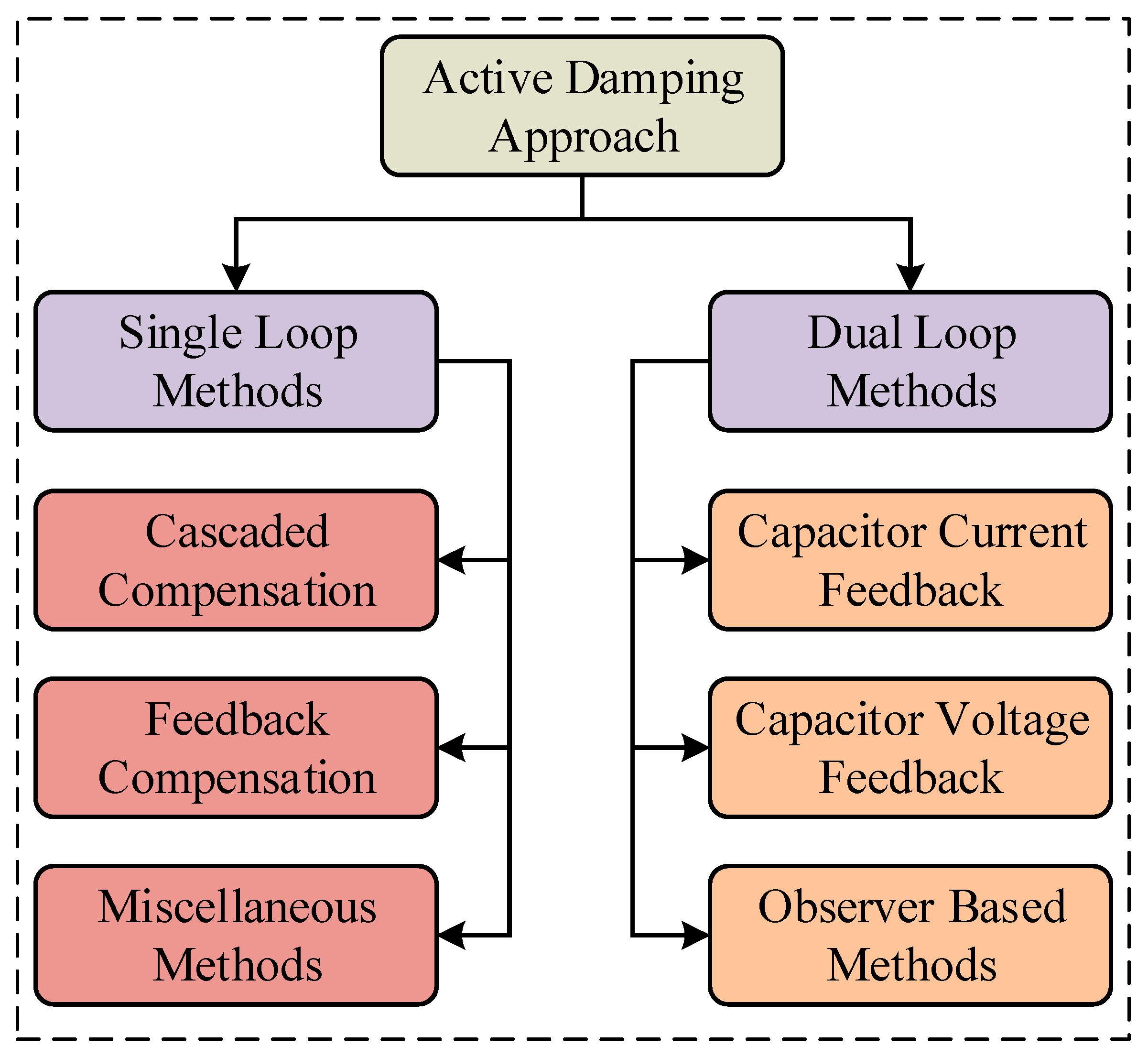
1.2. Literature Review
- Existing solutions for HF oscillation suppression in LCL filters often incur substantial implementation costs, creating a need for economically viable alternatives without compromising performance.
- While capacitor-current-feedback methods demonstrate effective resonance control, their reliance on additional current sensors increases system complexity and cost, highlighting the demand for accurate sensorless estimation techniques.
- Most control strategies exhibit sensitivity to LCL filter parameter variations—particularly in renewable energy applications where component tolerances and aging effects are significant—necessitating more adaptive solutions.
1.3. Contribution
- A cost-effective AD strategy is proposed for a single-phase LCL-filtered EV battery GCI system that minimizes hardware requirements to effectively mitigate HF oscillations in LCL filters.
- An innovative sensorless AD technique is developed, ensuring accurate performance without requiring any additional current sensors.
- The effective damping region is widened, ensuring system stability under LCL parameter variations and changing grid impedance conditions.
1.4. Organization
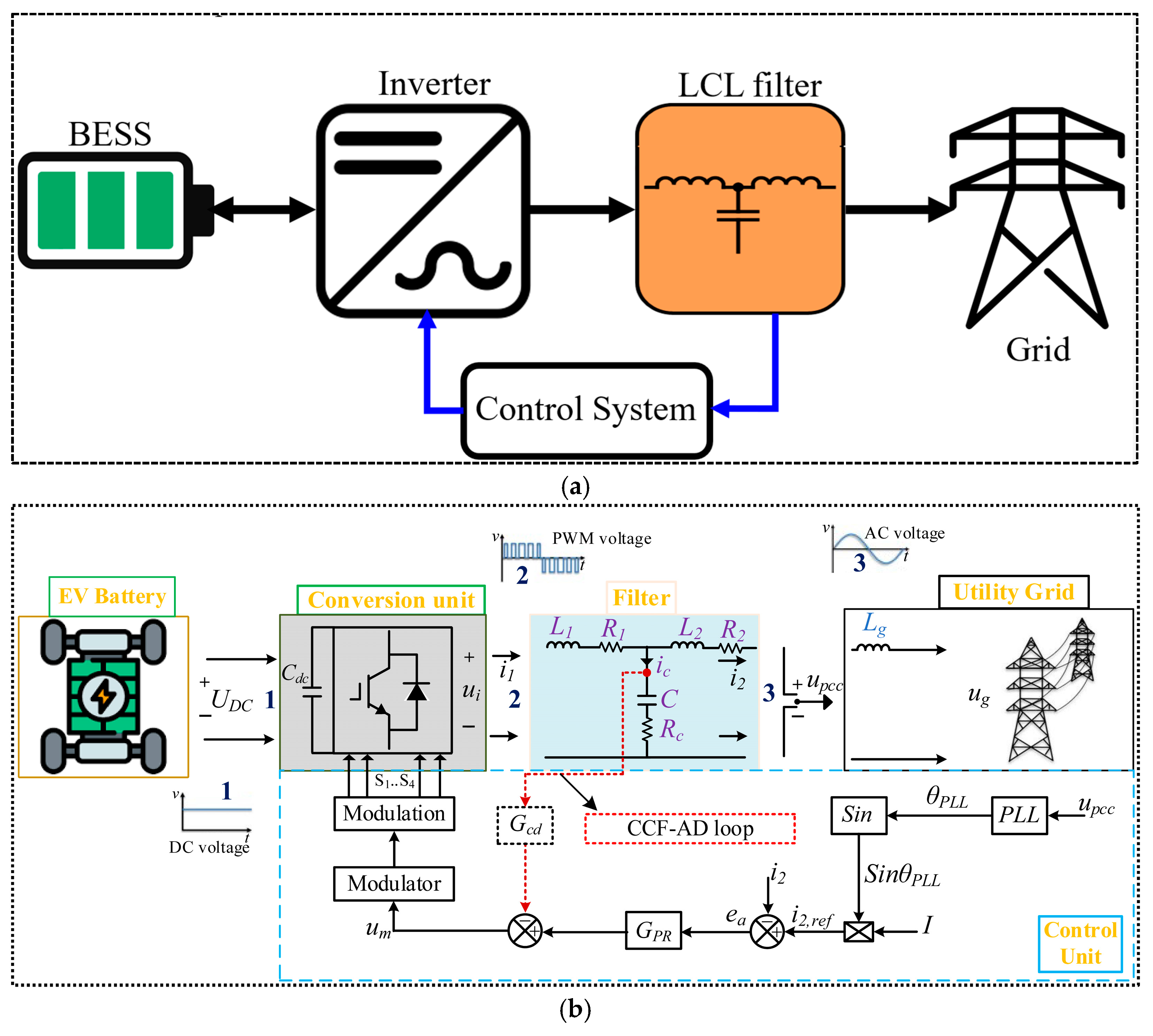
2. System Modelling
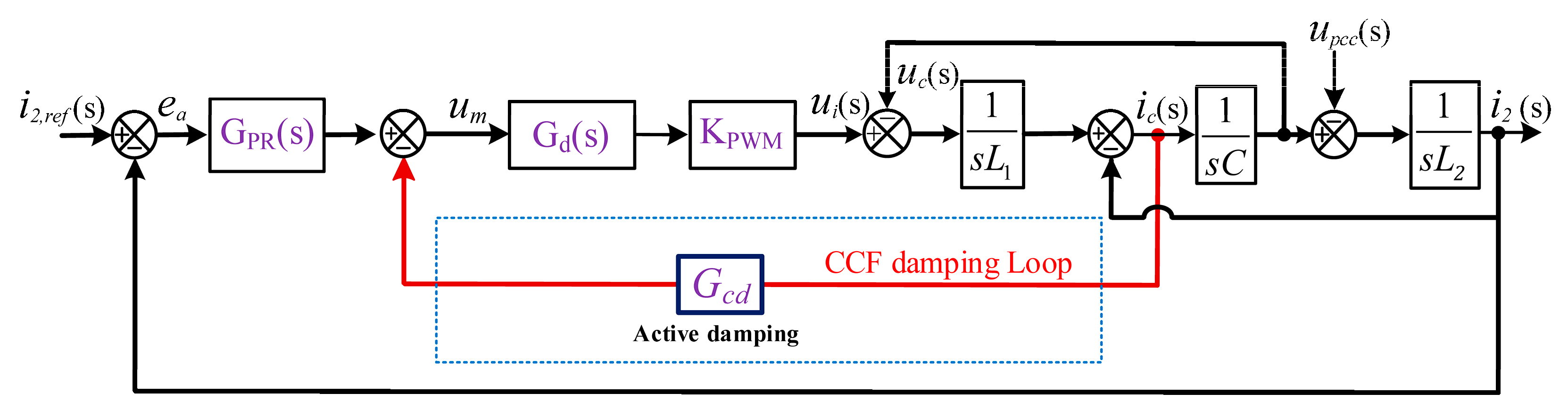
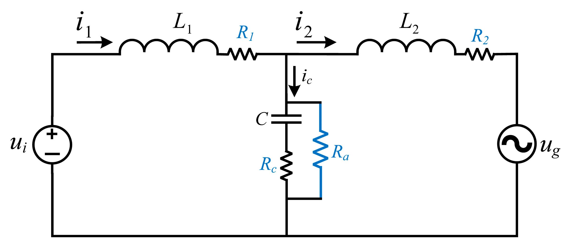
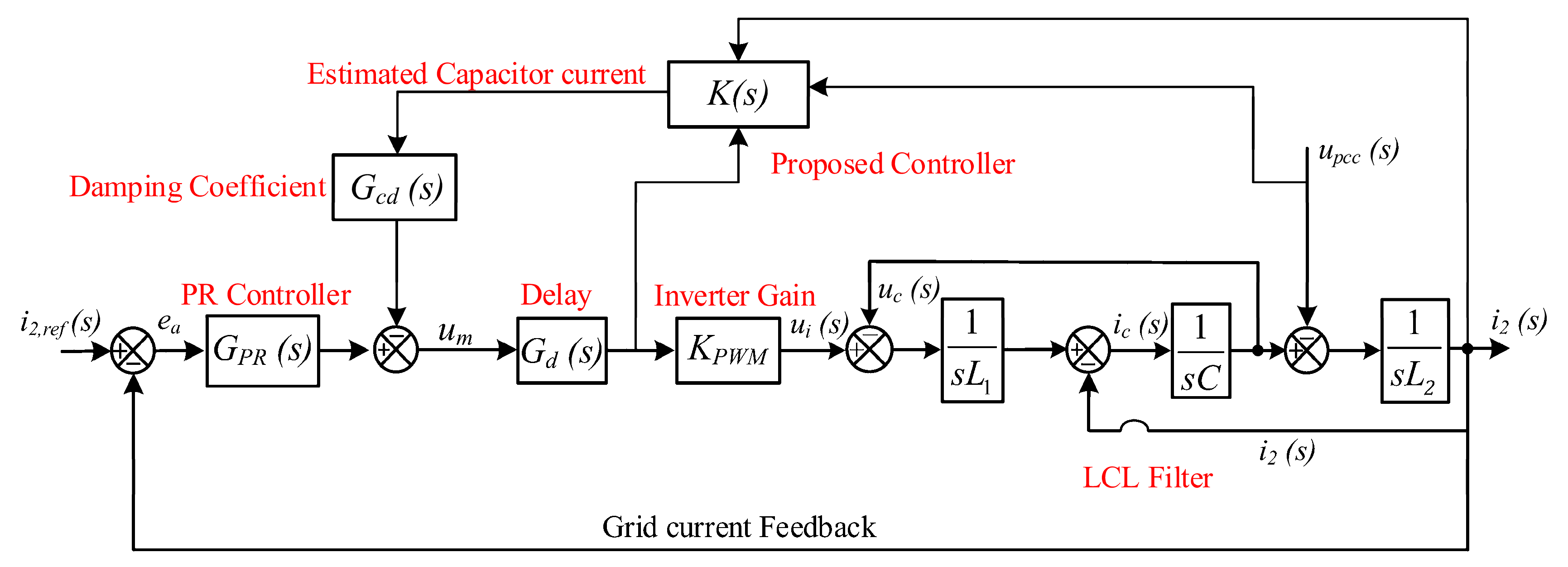
2.1. LCL Filter Modeling in GCI System with CCF-AD Loop
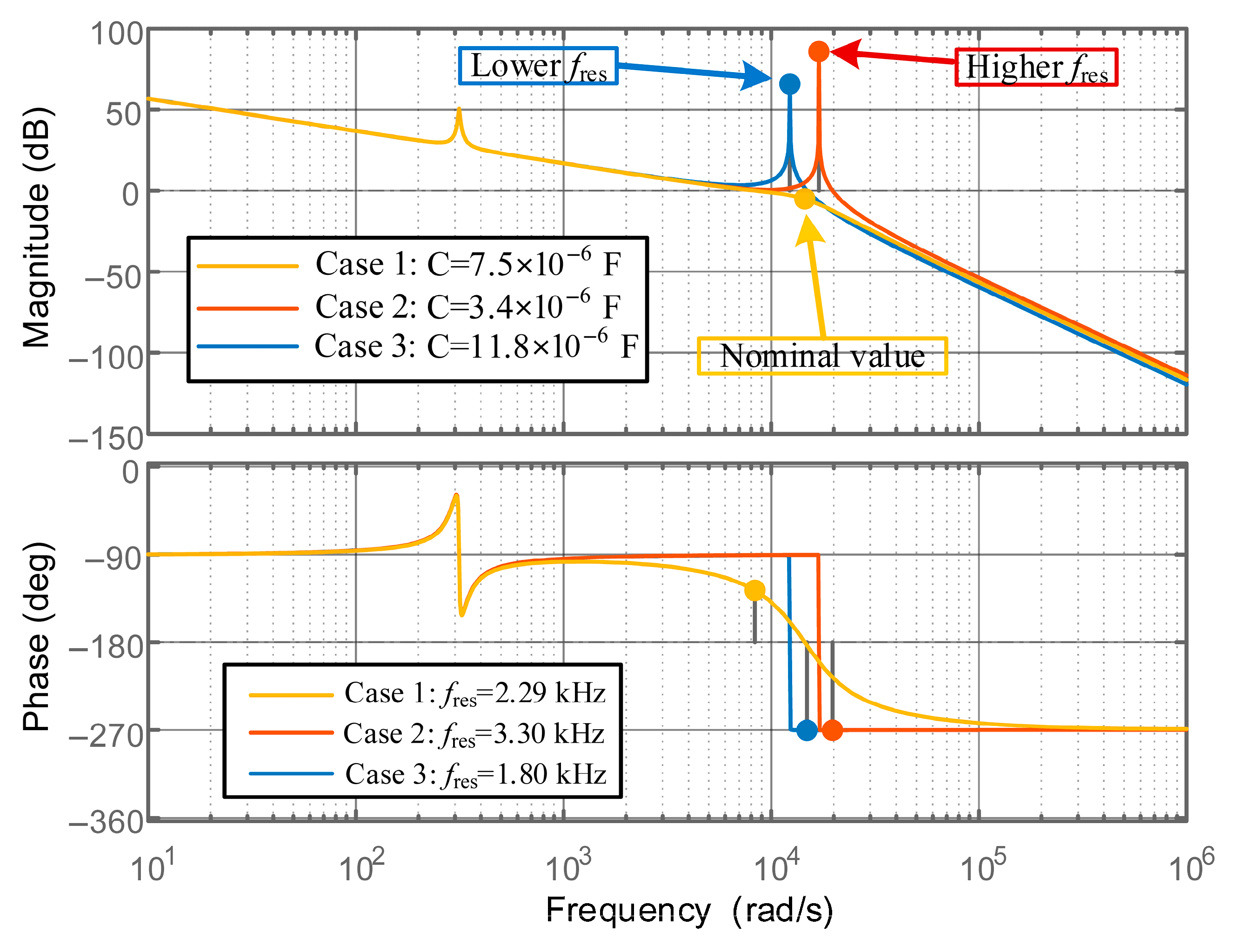
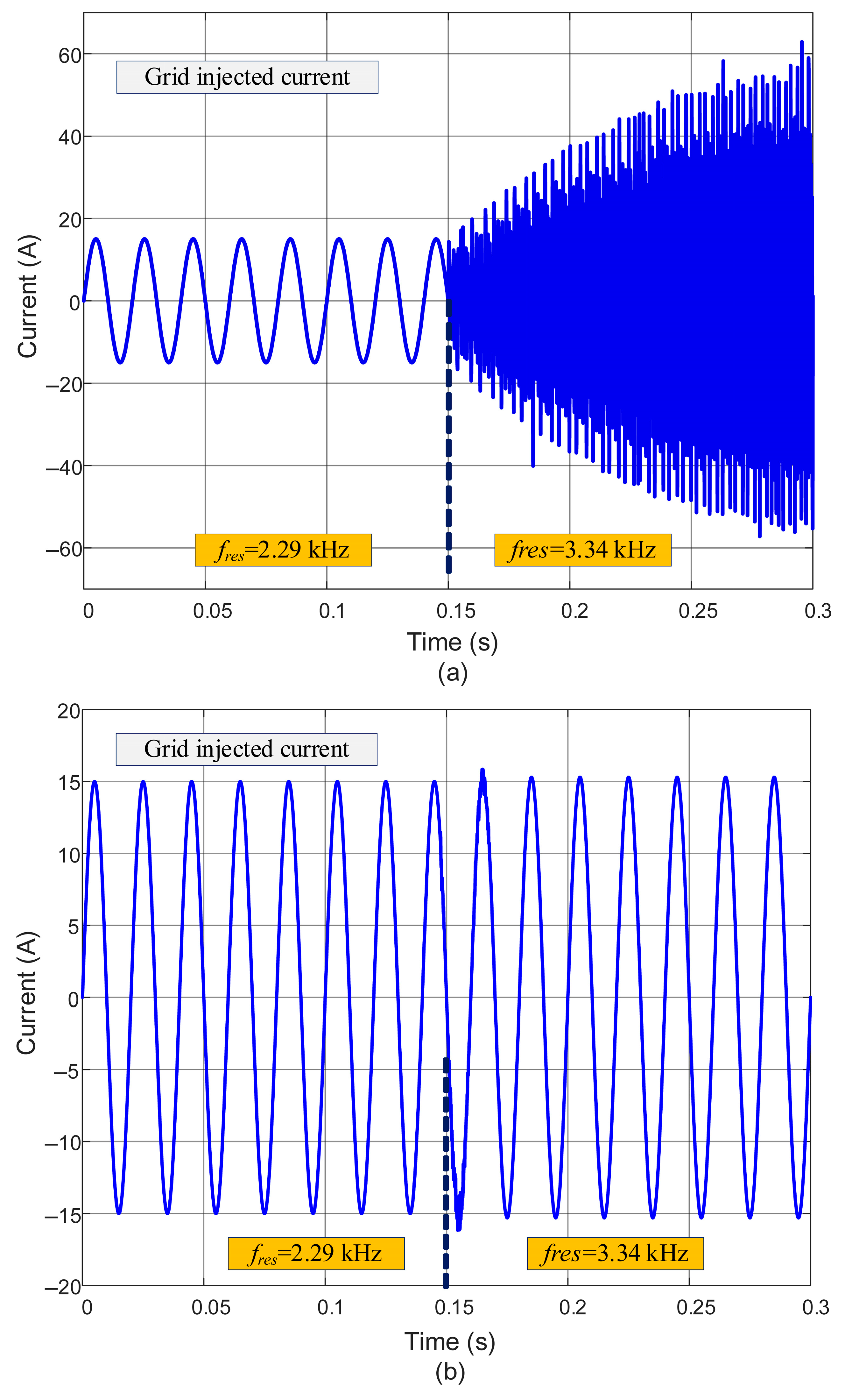
2.2. Stability Analysis of CCF-AD Under Resonance Frequency Shift
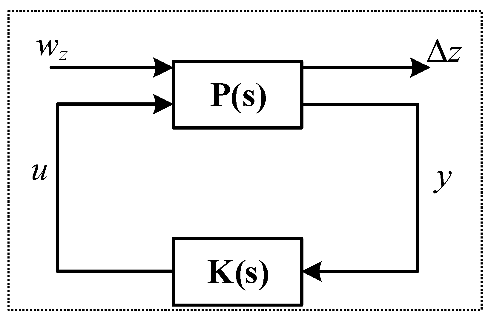
3. Active Damping with u-Synthesis Filter
3.1. Noise Process Model
3.2. Robust μ-Synthesis Filter Design
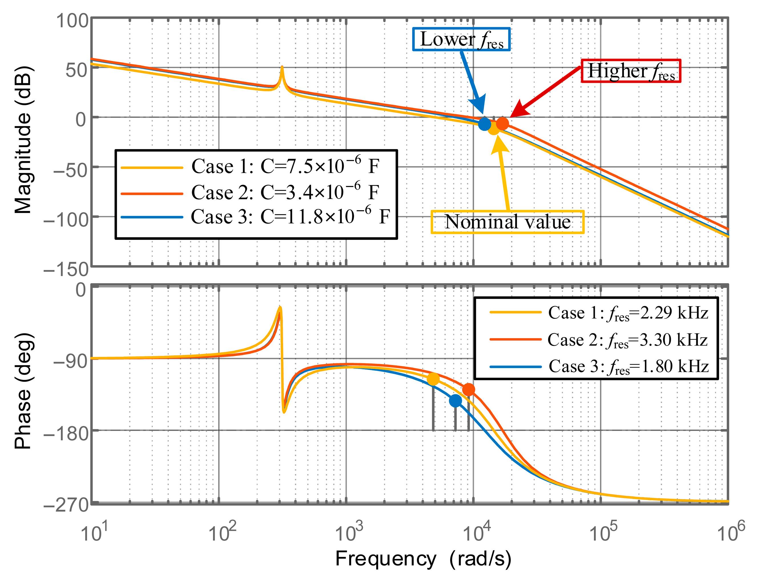
3.3. Frequency Response of the Proposed Control Scheme
4. Simulation Results
4.1. Steady-State Analysis
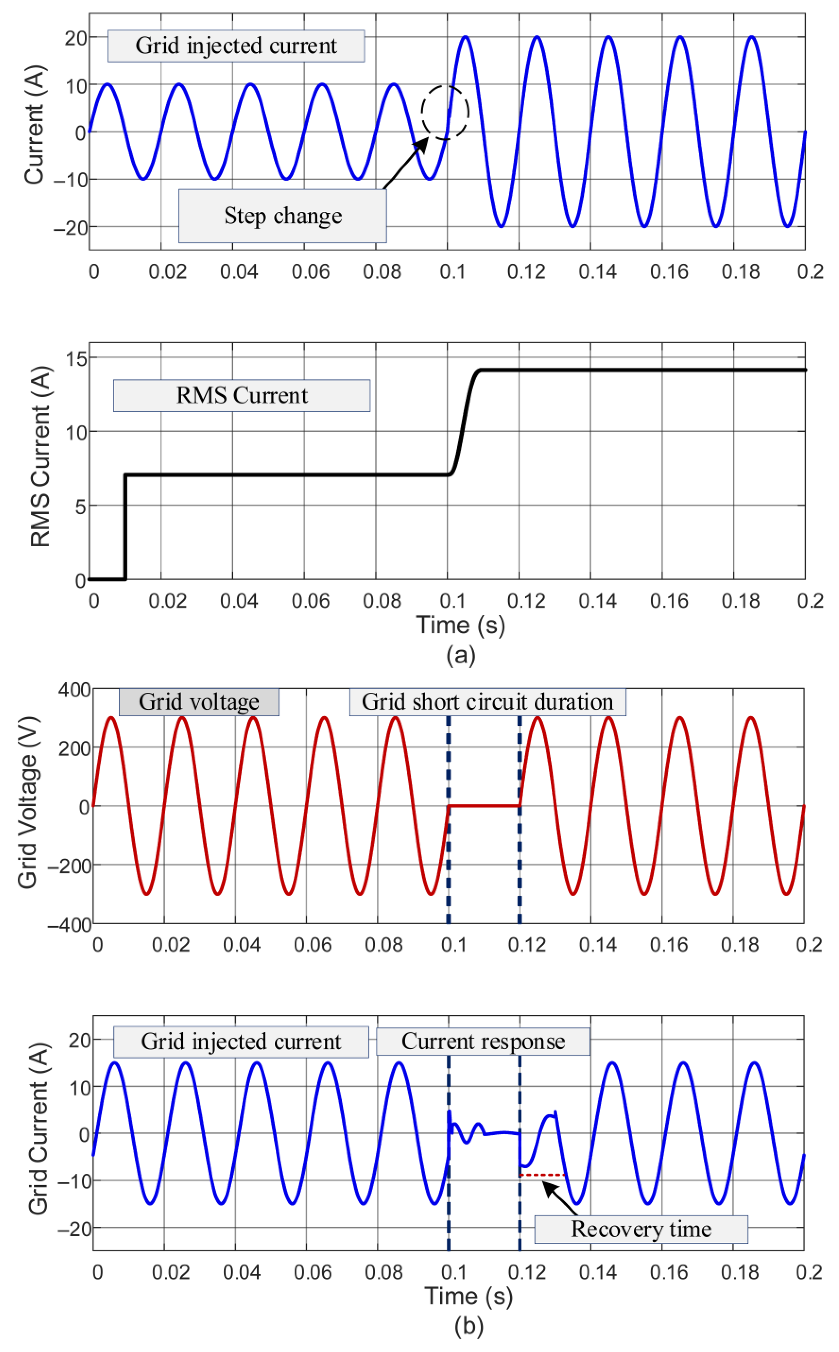
4.2. Transient-State Analysis
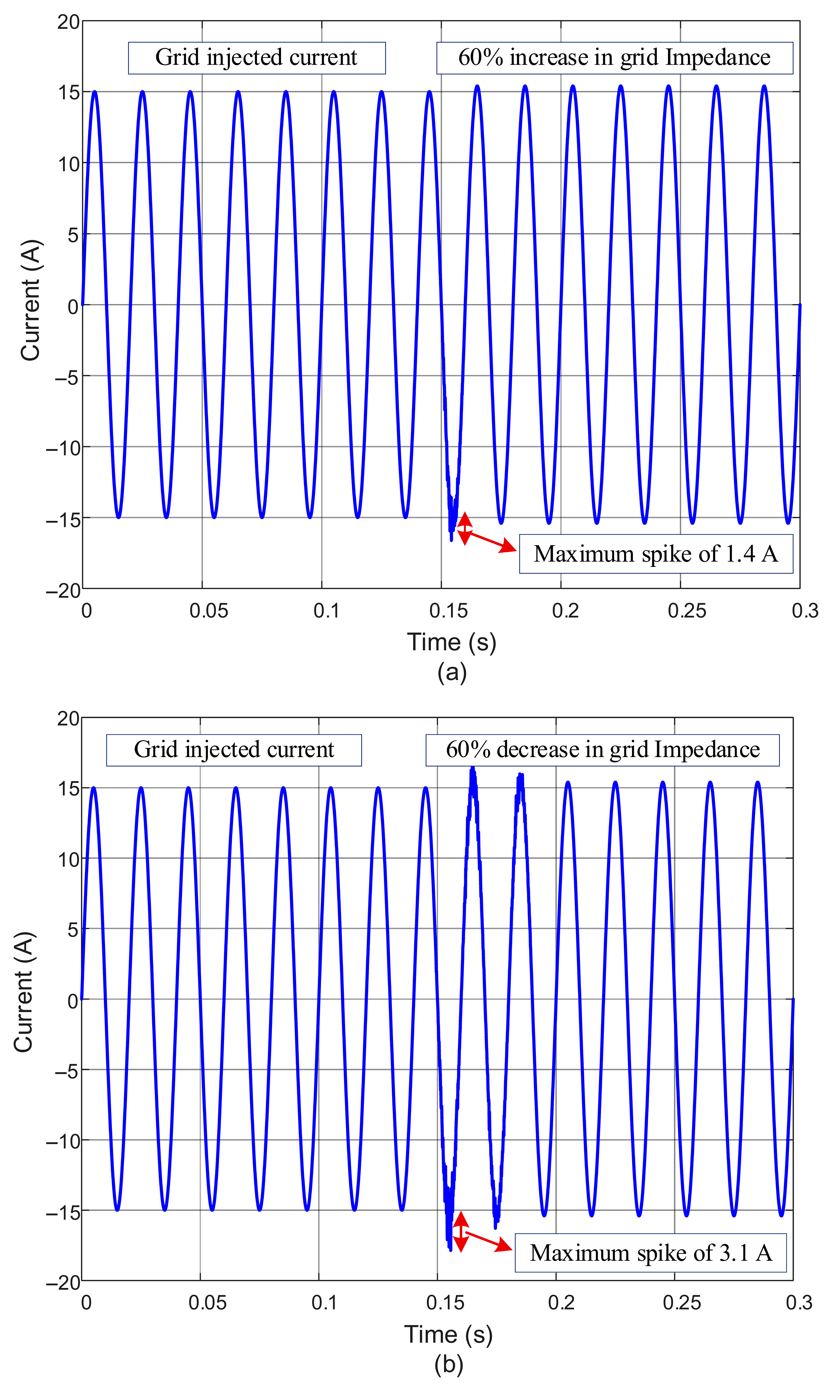
4.3. Robustness Evaluation
5. Experimental Results
5.1. Steady-State Analysis
5.2. Transient-State Analysis
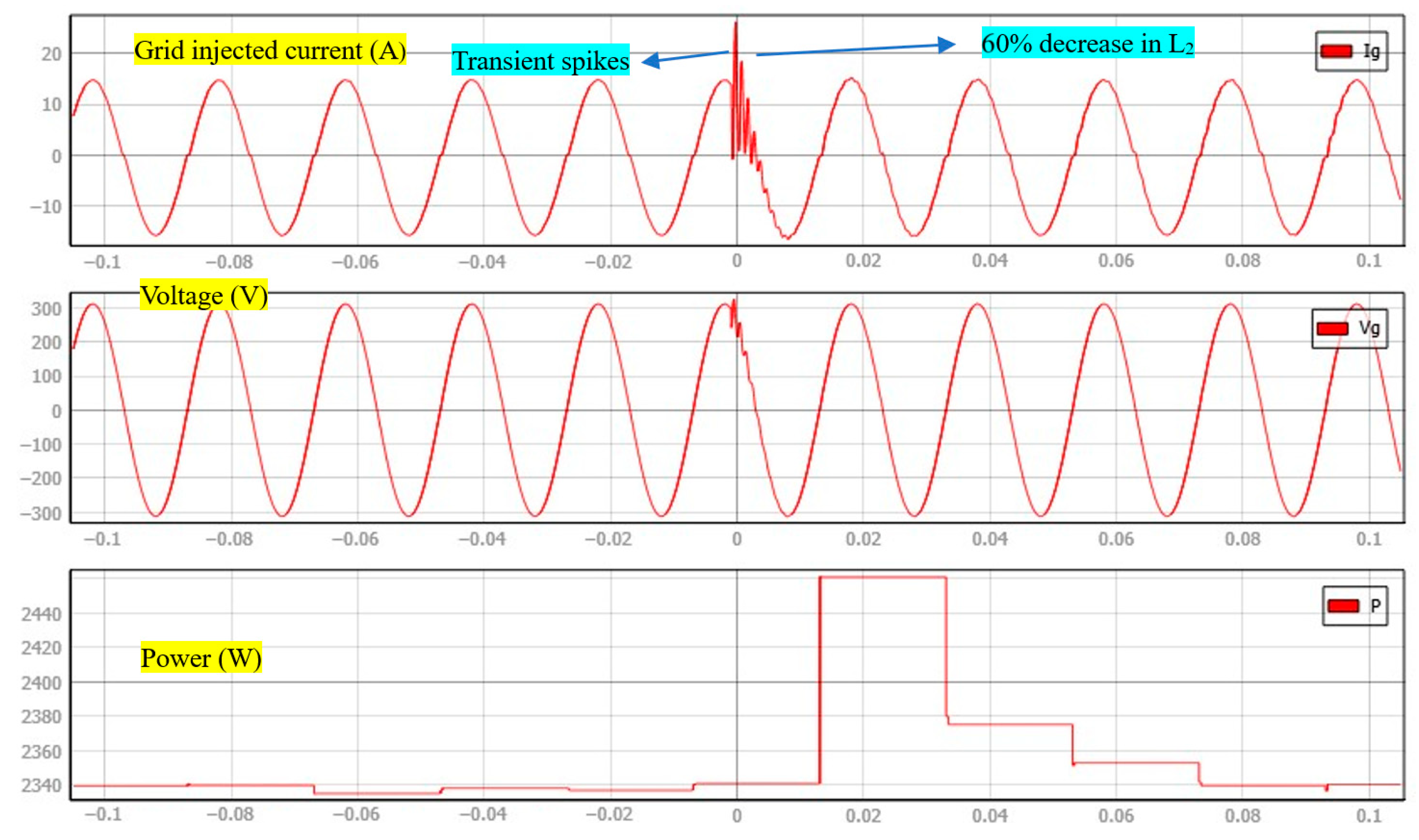
5.3. Robustness Evaluation
5.4. Discussion
6. Conclusions
Author Contributions
Funding
Data Availability Statement
Conflicts of Interest
Abbreviations
| DC-link voltage | |
| Inverter voltage | |
| Grid voltage | |
| Inverter-side inductor | |
| Filter capacitor | |
| Grid-side inductor | |
| Grid inductance | |
| Combination of and | |
| Inverter-side current | |
| Grid-side current | |
| Filter capacitor current | |
| Filter capacitor voltage | |
| PCC voltage | |
| Reference current | |
| Error signal | |
| Plant open loop TF with K(s) | |
| Inverter gain | |
| modulation signal | |
| Gate switching signals | |
| TF between and | |
| TF between and | |
| Plant open loop TF with PR | |
| Diagonal matrix | |
| External input matrix | |
| Composite Input matrix | |
| Plant matrix | |
| Input disturbance | |
| Angular resonance frequency | |
| Resonance frequency | |
| Sampling frequency | |
| Angular sampling frequency | |
| Sampling time-period | |
| Switching frequency | |
| Noise vector | |
| Parameter deviation matrix | |
| State transition matrix | |
| Nominal state matrix | |
| Switching time-period | |
| Proposed controlled output | |
| TF of delay | |
| Performance factor | γ |
| TF of PR controller | |
| Proportional gain | |
| Resonant gain | |
| Resonant cut-off frequency | |
| Angular line frequency | |
| Line frequency | |
| Rated power | |
| Inverter current magnitude | |
| Grid current magnitude | |
| Capacitor current magnitude | |
| PCC voltage magnitude | |
| Performance output | |
| Proposed controller |
References
- Cai, L.; Yang, C.; Li, J.; Liu, Y.; Yan, J.; Zou, X. Study on Frequency-Response Optimization of Electric Vehicle Participation in Energy Storage Considering the Strong Uncertainty Model. World Electr. Veh. J. 2025, 16, 35. [Google Scholar] [CrossRef]
- Aoun, A.; Adda, M.; Ilinca, A.; Ghandour, M.; Ibrahim, H. Dynamic Charging Optimization Algorithm for Electric Vehicles to Mitigate Grid Power Peaks. World Electr. Veh. J. 2024, 15, 324. [Google Scholar] [CrossRef]
- Mahlooji, M.H.; Mohammadi, H.R.; Rahimi, M. A review on modeling and control of grid-connected photovoltaic inverters with LCL filter. Renew. Sustain. Energy Rev. 2018, 81, 563–578. [Google Scholar] [CrossRef]
- Zhang, Y.; Song, C.; Wang, T.; Wang, K. Optimization of Passive Damping for LCL-Filtered AC Grid-Connected PV-Storage Integrated Systems. Electronics 2025, 14, 801. [Google Scholar] [CrossRef]
- Mazloum, N.; Khajehoddin, S.A. An efficient high-power-density integrated trap-LCL filter for inverters. IEEE Trans. Power Electron. 2025, 40, 1589–1608. [Google Scholar] [CrossRef]
- Ma, G.; Xie, C.; Li, C.; Zou, J.; Guerrero, J.M. Passivity-based design of passive damping for LCL-type grid-connected inverters to achieve full-frequency passive output admittance. IEEE Trans. Power Electron. 2023, 38, 16048–16060. [Google Scholar] [CrossRef]
- Wu, W.; Liu, Y.; He, Y.; Chung, H.S.H.; Liserre, M.; Blaabjerg, F. Damping Methods for Resonances Caused by LCL-Filter-Based Current-Controlled Grid-Tied Power Inverters: An Overview. IEEE Trans. Ind. Electron. 2017, 64, 7402–7413. [Google Scholar] [CrossRef]
- Kulkarni, A.; John, V. Mitigation of lower order harmonics in a grid-connected single-phase PV inverter. IEEE Trans. Power Electron. 2013, 28, 5024–5037. [Google Scholar] [CrossRef]
- Wang, X.; Blaabjerg, F.; Wu, W. Modeling and Analysis of Harmonic Stability in an AC Power-Electronics-Based Power System. IEEE Trans. Power Electron. 2014, 29, 6421–6432. [Google Scholar] [CrossRef]
- Fang, J.; Li, X.; Yang, X.; Tang, Y. An Integrated Trap-LCL Filter with Reduced Current Harmonics for Grid-Connected Converters under Weak Grid Conditions. IEEE Trans. Power Electron. 2017, 32, 8446–8457. [Google Scholar] [CrossRef]
- Li, F.; Zhang, X.; Zhu, H.; Li, H.; Yu, C. An LCL-LC filter for grid-connected converter: Topology, parameter, and analysis. IEEE Trans. Power Electron. 2015, 30, 5067–5077. [Google Scholar] [CrossRef]
- Xu, J.; Yang, J.; Ye, J.; Zhang, Z.; Shen, A. An LTCL filter for three-phase grid-connected converters. IEEE Trans. Power Electron. 2014, 29, 4322–4338. [Google Scholar] [CrossRef]
- Loh, P.C.; Holmes, D.G. Analysis of multiloop control strategies for LC/CL/LCL-filtered voltage-source and current-source inverters. IEEE Trans. Ind. Appl. 2005, 41, 644–654. [Google Scholar] [CrossRef]
- Xu, J.; Xie, S. LCL-resonance damping strategies for grid-connected inverters with LCL filters: A comprehensive review. J. Mod. Power Syst. Clean Energy 2018, 6, 292–305. [Google Scholar] [CrossRef]
- Upadhyay, N.; Padhy, N.P.; Agarwal, P. Grid-current control with inverter-current feedback active damping for LCL grid-connected inverter. IEEE Trans. Ind. Appl. 2024, 60, 1738–1749. [Google Scholar] [CrossRef]
- Gomes, C.C.; Cupertino, A.F.; Pereira, H.A. Damping techniques for grid-connected voltage source converters based on LCL filter: An overview. Renew. Sustain. Energy Rev. 2018, 81, 116–135. [Google Scholar] [CrossRef]
- Li, Y.; Gao, J.; Zhang, Z.; Wang, Q. Model-based and model-free predictive active damping for LCL-type active-front-end rectifiers. IEEE Trans. Ind. Electron. 2024, 71, 11754–11765. [Google Scholar] [CrossRef]
- Liu, Y.; Du, J.; Zhao, X.; Song, Y.; Wang, Y. High-Frequency Harmonic Suppression Strategy and Modified Notch Filter-Based Active Damping for Low-Inductance HPMSM. Appl. Sci. 2023, 13, 11309. [Google Scholar] [CrossRef]
- Wang, B.; Zhao, Q.; Zhang, G.; Zhang, H.; Liu, K.; Yue, X. Novel Active Damping Design Based on a Biquad Filter for an LLCL Grid-Tied Inverter. Energies 2023, 16, 1093. [Google Scholar] [CrossRef]
- Zhang, X.; Tan, L.; Xian, J.; Zhang, H.; Ma, Z.; Kang, J. Direct grid-side current model predictive control for grid-connected inverter with LCL filter. IET Power Electron. 2018, 11, 2450–2460. [Google Scholar] [CrossRef]
- Li, X.; Wu, X.; Geng, Y.; Yuan, X.; Xia, C.; Zhang, X. Wide damping region for LCL-type grid-connected inverter with an improved capacitor-current-feedback method. IEEE Trans. Power Electron. 2015, 30, 5247–5259. [Google Scholar] [CrossRef]
- Chen, Y.; Xie, Z.; Zhou, L.; Wang, Z.; Zhou, X.; Wu, W.; Yang, L.; Luo, A. Optimized design method for grid-current-feedback active damping to improve dynamic characteristic of LCL-type grid-connected inverter. Int. J. Electr. Power Energy Syst. 2018, 100, 19–28. [Google Scholar] [CrossRef]
- Vieira, R.P.; Martins, L.T.; Massing, J.R.; Stefanello, M. Sliding mode controller in a multiloop framework for a grid-connected VSI with LCL filter. IEEE Trans. Ind. Electron. 2018, 65, 4714–4723. [Google Scholar] [CrossRef]
- Liu, J.; Yin, Y.; Luo, W.; Vazquez, S.; Franquelo, L.G.; Wu, L. Sliding mode control of a three-phase AC/DC voltage source converter under unknown load conditions: Industry applications. IEEE Trans. Syst. Man Cybern. Syst. 2017, 48, 1771–1780. [Google Scholar] [CrossRef]
- Hollweg, G.V.; Evald, P.D.O.; Tambara, R.V.; Gründling, H.A. Adaptive super-twisting sliding mode for DC-AC converters in very weak grids. Int. J. Electron. 2023, 110, 1808–1833. [Google Scholar] [CrossRef]
- Zhou, L.; Zhou, X.; Chen, Y.; Lv, Z.; He, Z.; Wu, W.; Yang, L.; Yan, K.; Luo, A.; Guerrero, J.M. Inverter-Current-Feedback Resonance-Suppression Method for LCL-Type DG System to Reduce Resonance-Frequency Offset and Grid-Inductance Effect. IEEE Trans. Ind. Electron. 2018, 65, 7036–7048. [Google Scholar] [CrossRef]
- Zhang, H.; Wang, X.; He, Y.; Pan, D.; Ruan, X. A compensation method to eliminate the impact of time delay on capacitor-current active damping. IEEE Trans. Ind. Electron. 2022, 69, 7512–7516. [Google Scholar] [CrossRef]
- Wang, X.; Blaabjerg, F.; Loh, P.C. Virtual RC damping of LCL-filtered voltage source converters with extended selective harmonic compensation. IEEE Trans. Power Electron. 2015, 30, 4726–4737. [Google Scholar] [CrossRef]
- Shahed, M.T.; Rashid, A.B.M.H. Battery charging technologies and standards for electric vehicles: A state-of-the-art review, challenges, and future research prospects. Energy Rep. 2024, 11, 5978–5998. [Google Scholar] [CrossRef]
- Sahoo, A.; Ravishankar, J.; Jones, C. Phase-Locked Loop Independent Second-Order Generalized Integrator for Single-Phase Grid Synchronization. IEEE Trans. Instrum. Meas. 2021, 70, 9004409. [Google Scholar] [CrossRef]
- IEEE Std 1547-2018 (Revision of IEEE Std 1547-2003); IEEE Standard for Interconnection and Interoperability of Distributed Energy Resources with Associated Electric Power Systems Interfaces. IEEE: Piscataway, NJ, USA, 2018; pp. 1–138. [CrossRef]
- Athari, H.; Niroomand, M.; Ataei, M. Review and Classification of Control Systems in Grid-tied Inverters. Renew. Sustain. Energy Rev. 2017, 72, 1167–1176. [Google Scholar] [CrossRef]
- Khan, D.; Zhu, K.; Hu, P.; Waseem, M.; Ahmed, E.M.; Lin, Z. Active damping of LCL-filtered grid-connected inverter based on parallel feedforward compensation strategy. Ain Shams Eng. J. 2023, 14, 101902. [Google Scholar] [CrossRef]
- Walker, R.A.; Emami-Naeini, A.; Dooren, P.V. A general algorithm for solving the algebraic Riccati equation. In Proceedings of the 1982 21st IEEE Conference on Decision and Control, Orlando, FL, USA, 8–10 December 1982; pp. 68–72. [Google Scholar] [CrossRef]
- Khan, D.; Qais, M.; Sami, I.; Hu, P.; Zhu, K.; Abdelaziz, A.Y. Optimal LCL-Filter Design for a Single-Phase Grid-Connected Inverter Using Metaheuristic Algorithms. Comput. Electr. Eng. 2023, 110, 108857. [Google Scholar] [CrossRef]
- IEEE Std 1547.1 2005; IEEE Standards Coordinating Committee 21. IEEE Standard Conformance Test Procedures for Equipment Interconnecting Distributed Resources with Electric Power Systems. IEEE: Piscataway, NJ, USA, 2005. [CrossRef]
- Guo, A.; Tian, Y.; Zhao, H. Highly Robust Active Damping Approach for Grid-Connected Current Feedback Using Phase-Lead Compensation. Electronics 2025, 14, 309. [Google Scholar] [CrossRef]
- Zhang, X.; Xie, Y.; Wu, R. A Capacitor-Current-Feedback Active Damping Control Strategy with Phase Lead Compensation for LCL-Type Grid-Connected Inverter. IEEE Access 2024, 12, 193663–193675. [Google Scholar] [CrossRef]


| Parameter | Symbol | Value |
|---|---|---|
| Operating voltage | U | 380.0 V |
| Rated capacity | 5.0 Ah | |
| Battery response time | 30.0 s | |
| Open circuit voltage | 379.5257 V | |
| Internal resistance | 0.70 ohm | |
| Polarization constant | 0.51442 | |
| Amplitude of exponential zone | 29.2917 | |
| Inverse exponential zone time constant | 12.2024 | |
| Discharge current | 10.62 A |
| Parameter | Symbol | Value |
|---|---|---|
| Rated power | P | 5 kW |
| Grid voltage (RMS) | Ug,rms | 230 V |
| Grid frequency | fL | 50 Hz |
| Sampling frequency | fs | 20 kHz |
| Switching frequency | fsw | 10 kHz |
| Inverter-side inductance | 2.82 mH | |
| Grid-side inductance | 0.81 mH | |
| Filter capacitance | C | 7.5 µF |
| Proportional gain | 17.9 | |
| Integral gain | 358.434 | |
| Cutoff frequency | 2.5 rad/s |
| Performance Parameters | Proposed Method | [37] | [38] | [26] |
|---|---|---|---|---|
| Steady state | Excellent | Excellent | Excellent | Excellent |
| Transient attenuation | Excellent | satisfactory | satisfactory | Excellent |
| Tracking performance | Better | Better | Better | Better |
| Higher resonance frequency | Superior | Inferior | Marginal | Superior |
| Grid impedance | High | Lower | Marginal | Marginal |
| Sensor count | Fewer | Higher | Higher | Higher |
| Tunning | Yes | No | No | No |
| Complexity | Lower | Higher | Higher | Higher |
Disclaimer/Publisher’s Note: The statements, opinions and data contained in all publications are solely those of the individual author(s) and contributor(s) and not of MDPI and/or the editor(s). MDPI and/or the editor(s) disclaim responsibility for any injury to people or property resulting from any ideas, methods, instructions or products referred to in the content. |
© 2025 by the authors. Published by MDPI on behalf of the World Electric Vehicle Association. Licensee MDPI, Basel, Switzerland. This article is an open access article distributed under the terms and conditions of the Creative Commons Attribution (CC BY) license (https://creativecommons.org/licenses/by/4.0/).
Share and Cite
Khan, N.; Cheng, W.; Khan, M.Y.A.; Khan, D. Robust Sensorless Active Damping of LCL Resonance in EV Battery Grid-Tied Converters Using μ-Synthesis Control. World Electr. Veh. J. 2025, 16, 422. https://doi.org/10.3390/wevj16080422
Khan N, Cheng W, Khan MYA, Khan D. Robust Sensorless Active Damping of LCL Resonance in EV Battery Grid-Tied Converters Using μ-Synthesis Control. World Electric Vehicle Journal. 2025; 16(8):422. https://doi.org/10.3390/wevj16080422
Chicago/Turabian StyleKhan, Nabeel, Wang Cheng, Muhammad Yasir Ali Khan, and Danish Khan. 2025. "Robust Sensorless Active Damping of LCL Resonance in EV Battery Grid-Tied Converters Using μ-Synthesis Control" World Electric Vehicle Journal 16, no. 8: 422. https://doi.org/10.3390/wevj16080422
APA StyleKhan, N., Cheng, W., Khan, M. Y. A., & Khan, D. (2025). Robust Sensorless Active Damping of LCL Resonance in EV Battery Grid-Tied Converters Using μ-Synthesis Control. World Electric Vehicle Journal, 16(8), 422. https://doi.org/10.3390/wevj16080422