Article

Coordinated Slip Ratio and Yaw Moment Control for Formula Student Electric Racing Car

1
School of Traffic Engineering, Nanjing Institute of Technology, Nanjing 211167, China
2
National Key Laboratory of Automotive Chassis Integration and Bionics, Changchun 130015, China
*
Author to whom correspondence should be addressed.
World Electr. Veh. J. 2025, 16(8), 421; https://doi.org/10.3390/wevj16080421
Submission received: 20 May 2025 / Revised: 19 July 2025 / Accepted: 25 July 2025 / Published: 26 July 2025

Abstract

The design and optimization of drive distribution strategies are critical for enhancing the performance of Formula Student electric racing cars, which face demanding operational conditions such as rapid acceleration, tight cornering, and variable track surfaces. Given the increasing complexity of racing environments and the need for adaptive control solutions, a multi-mode adaptive drive distribution strategy for four-wheel-drive Formula Student electric racing cars is proposed in this study to meet specialized operational demands. Based on the dynamic characteristics of standardized test scenarios (e.g., straight-line acceleration and figure-eight loop), two control modes are designed: slip-ratio-based anti-slip control for longitudinal dynamics and direct yaw moment control for lateral stability. A CarSim–Simulink co-simulation platform is established, with test scenarios conforming to competition standards, including variable road adhesion coefficients (μ is 0.3–0.9) and composite curves. Simulation results indicate that, compared to conventional PID control, the proposed strategy reduces the peak slip ratio to the optimal range of 18% during acceleration and enhances lateral stability in the figure-eight loop, maintaining the sideslip angle around −0.3°. These findings demonstrate the potential for significant improvements in both performance and safety, offering a scalable framework for future developments in racing vehicle control systems.

Graphical Abstract

1. Introduction

With the advancement of electrification, four-motor drive has been identified as a key direction for technological innovation in the Formula Student electric racing car. By achieving precise decoupled control of torque for each wheel through independent drive units, additional degrees of freedom are provided for vehicle dynamic control. Figure 1 shows the system breakdown diagram of the Formula Student electric racing car. While both thermal management and motor control are critical to vehicle performance and reliability, the extreme operational demands of racing—such as rapid acceleration, high-speed cornering, and dynamic road surface variations—necessitate a primary focus on real-time motor control strategies to optimize traction and stability. Therefore, the development of the drive distribution system is prioritized in this study, while it is acknowledged that thermal constraints [1] remain an important consideration for future work. Scholars have conducted extensive research on drive force distribution strategies. Wang et al. [2] improve the handling stability of the vehicle on the road with different adhesion levels by means of a hierarchical control of the drive force distribution strategy. Zhai et al. [3] reduce the error of yaw rate and sideslip angle by as much as 47.1% and 50.3% compared with the general controller by means of the two-level optimal torque distribution control strategy. Peng et al. [4] improved the safety, energy efficiency, and maneuvering stability of the vehicle through a four-wheel independently driven steering wheel dynamic torque coordinated hierarchical control strategy. Zou et al. [5] designed a novel synchronizer-shift structure through a real-time hierarchical control algorithm, and the proposed powertrain could improve the acceleration by 38% compared to the power split hybrid transmissions, and reduce the series-parallel hybrid transmissions by 4.88~8.48% energy consumption. Chen et al. [6] improved the steering maneuverability and high-speed stability of the vehicle for small radius driving using a hierarchical control structure that effectively suppressed the chattering and jittering of the vehicle state parameters and the motor torque. Based on hierarchical control, Mirzaei et al. [7] proposed a design method for vehicle lateral stability control, which is more efficient than methods based on numerical optimization. Ao et al. [8] optimized the power dissipation generated by the extra yawing torque and enhanced the lateral stability of the four-wheel-drive electric vehicle by using the model predictive control with an adaptive sliding mode control strategy. Zha et al. [9] effectively improved the stability and safety of a four-wheel independent drive vehicle while meeting the driving dynamics requirements by using Model Predictive Control (MPC) with vehicle stability set as the optimization objective and motor limit torque as a constraint.
Qi et al. [10] proposed an adaptive model predictive control (MPC) method based on extended Kalman filtering (EKF) for tire lateral stiffness, which significantly improved the path tracking accuracy and lateral stability of distributed drive electric vehicles under extreme conditions by integrating active front steering (AFS) and direct yaw moment control (DYC). Zhang et al. [11] achieved the synergistic optimization of vehicle motion control accuracy and response speed by using a fuzzy PID-based yaw moment control algorithm. Sankhwar [12] achieved motor speed control through q-axis current feedback and a PID controller. To address the overshoot and instability issues caused by the inertia of hub motors in adaptive PID control, Zhang [13] designed a variable step size regulation method based on fuzzy control, which effectively suppressed system overshoot and shortened the steady-state regulation time. Jabari [14] proposed an optimization strategy based on edge computing, combining the Dung Beetle Optimizer (DBO) and Ant-Lion Optimizer (ALO) algorithms, which significantly improved the speed control performance of Switch Reluctance Motors (SRMs) and reduced torque ripple. The study achieved faster convergence speed and lower computational complexity under dynamic load conditions through the use of cascaded PID and Fractional-Order PID (FOPID) controllers. To address the speed tracking problem in brushless DC motor drives, Hasan et al. [15] proposed an Adaptive Neural Fuzzy Nonlinear PID controller (ANF-NLPID) that combines an Improved Particle Swarm Optimization algorithm (IPSO-CT) to effectively eliminate external interference caused by environmental or internal problems and uncertainties caused by parameter changes, significantly improving speed tracking performance and reducing energy consumption. Silva et al. [16] designed an electronic differential controller based on fuzzy control, which effectively corrected the vehicle’s trajectory in certain specific operations. Chen et al. [17] optimized the torque distribution strategy by applying fuzzy PID control to maintain an additional yaw moment for stable vehicle operation, thereby effectively controlling the vehicle’s center of gravity lateral deviation angle. Wang et al. [18] employed fuzzy logic control to dynamically adjust the weighting coefficients of optimization objectives, significantly enhancing the effectiveness of energy management strategies; Liu et al. [19] utilized neural networks to construct an optimal equivalent factor prediction model, achieving significant improvements in fuel economy under the New European Driving Cycle (NEDC) and Worldwide Harmonized Light Vehicle Test Cycle (WLTC) conditions. Based on the independent controllability of hub motors, Yao et al. [20] developed a drive force allocation algorithm targeting optimal traction performance, effectively reducing tire traction load while meeting the driver’s longitudinal power requirements. Patel et al. [21] designed an electronic differential control strategy that intelligently distributes torque between the two electric motors on the rear axle based on the vehicle’s yaw rate, demonstrating that this electronic differential control strategy effectively improves the vehicle’s turning performance. Adnane et al. [22] proposed a Multi-Ensemble Learning (MEL)-based Energy Management Strategy (EMS) for Dual-Motor Electric Vehicles (DMEVs), which dynamically distributes torque between front and rear motors in real-time to minimize energy consumption. Halimi et al. [23] achieved highly robust and high-performance control of sensorless induction motors by combining backstepping control and high-order sliding mode control, effectively reducing the chattering phenomenon in traditional sliding mode control. Saputra et al. [24] designed a PLC-based PID controller for DC motor speed control, utilizing MATLAB Tuner and system identification to achieve fast response and minimal steady-state error. The study highlighted that while MATLAB Tuner eliminated steady-state errors, it introduced oscillations during transient states, necessitating further fine-tuning. Based on Artificial Neural Networks (ANN), Oubelaid et al. [25] proposed a torque distribution strategy for hybrid vehicles that significantly improves driving comfort and power efficiency in complex road conditions by dynamically adjusting the torque distribution ratio between the front and rear wheels.
In summary, various drive force allocation strategies, such as hierarchical control, Model Predictive Control (MPC), and fuzzy logic control, have been proposed; however, a unified theoretical framework has yet to be established. Given the complex operating conditions and high-performance demands of the Formula Student Electric Competition, reliance on a single control strategy remains insufficient. Thus, the development of application-specific drive force allocation strategies holds both theoretical significance and practical engineering value.
In this paper, based on the independent regulation ability of four-motor drive, the optimal drive control strategy of the sliding rate is proposed for the characteristics of easy sliding of tires in linear acceleration condition; for the figure-eight loop condition, the fuzzy control model of direct transverse moment is constructed, and the control strategy in two cases is simulated and analyzed. Beyond immediate racing applications, this research contributes to the broader development of adaptive control systems for electric vehicles, offering insights that could inform future advancements in autonomous racing, high-performance EVs, and safety-critical vehicle dynamic control under variable road conditions. The paper is structured as follows: In Section 1, a comprehensive review of state-of-the-art solutions is presented, and the control strategy adopted in this paper is described. Section 2 is devoted to the description of the vehicle specifications and standardized test scenarios. The development of the three-degree-of-freedom dynamic model and its Simulink implementation are described in Section 3. The validation of the accuracy of the proposed control strategy is provided in Section 4. In Section 5, a performance comparison of the control strategy with the conventional PID control architecture is analyzed. Finally, the basic theoretical advances are summarized in Section 6 and Section 7, and the main research directions for future development are identified.

2. Racing Parameters and Conditions

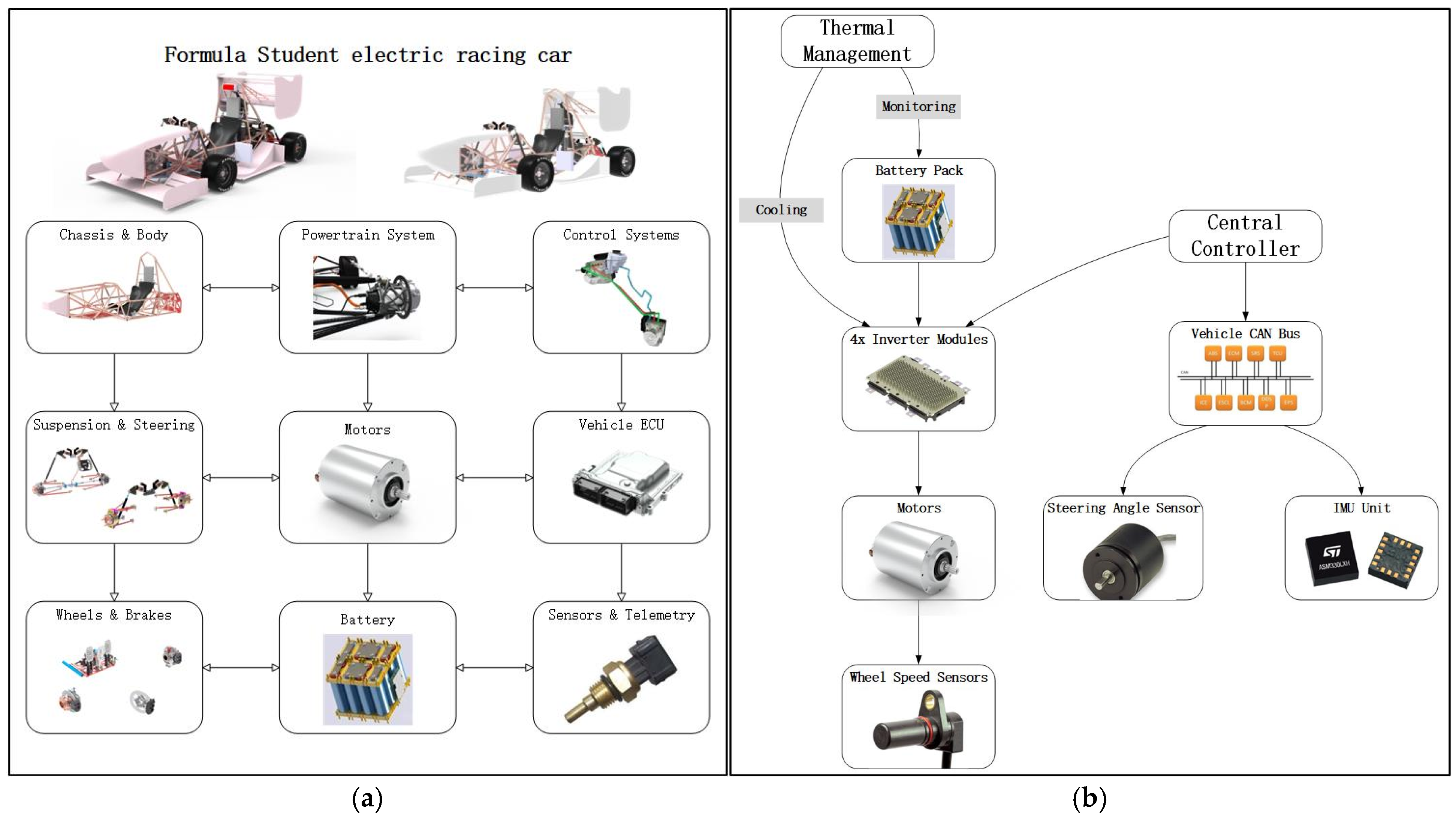
2.1. Racing Parameters

Based on the structural parameters of the Formula Student electric racing car, a simulation model is developed in CarSim, while the motor model is constructed in MATLAB/Simulink. As the study primarily focuses on drive force distribution under various operating conditions, high-fidelity motor modeling is not required. Therefore, motor complexity is neglected, and only input–output characteristics are considered to achieve a simplified motor model. The model, built using MATLAB/Simulink, takes motor speed and vehicle velocity as inputs and outputs the corresponding motor torque, effectively capturing the motor’s real-time performance during race conditions.
The parameters related to the formula racing car, motor, and battery are shown in Table 1. All the parameters are from Nanjing Institute of Technology’s formula racing car.

2.2. Analysis of Working Conditions

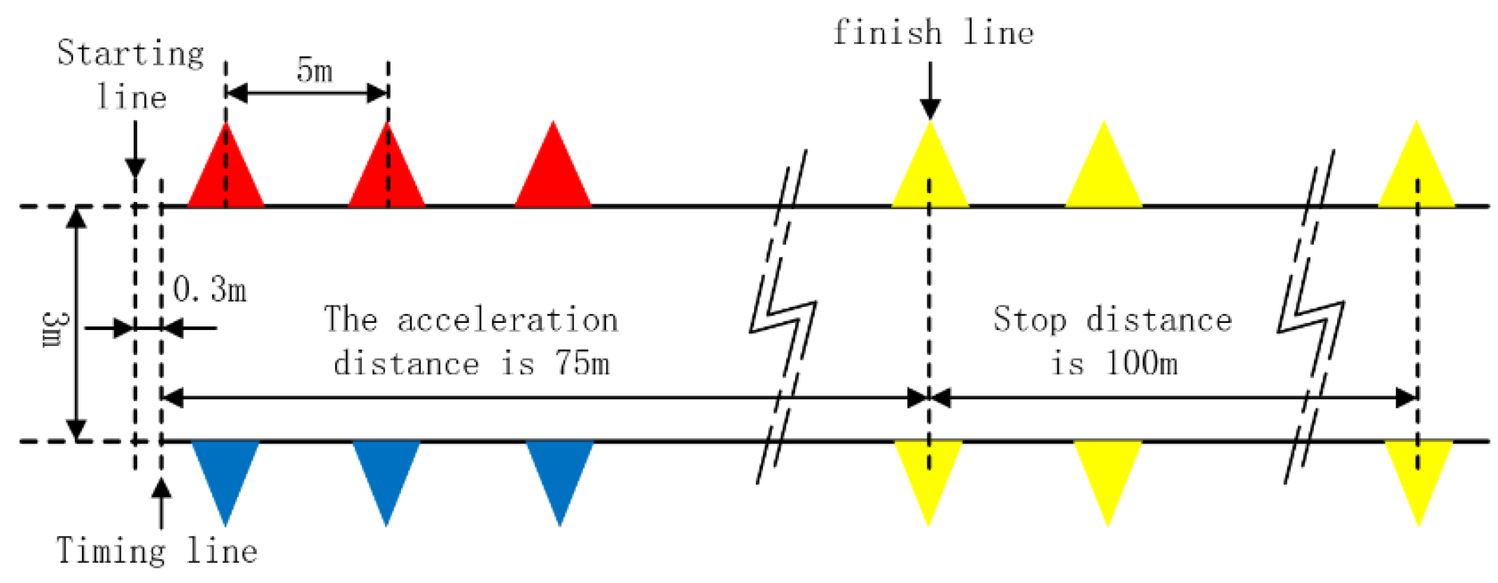
2.2.1. Straight-Line Acceleration Condition

The straight-line acceleration stage is defined over a 75 m distance, requiring the vehicle to accelerate from a complete standstill to the end of the track. Accurate state estimation during this phase is essential to ensure reliable performance in subsequent events. The detailed track layout and dimensions are presented in Figure 2.
The working condition is configured as follows: a 75 m straight track with a road adhesion coefficient set at 0.8, each motor delivers a torque output of 20 N∙m.

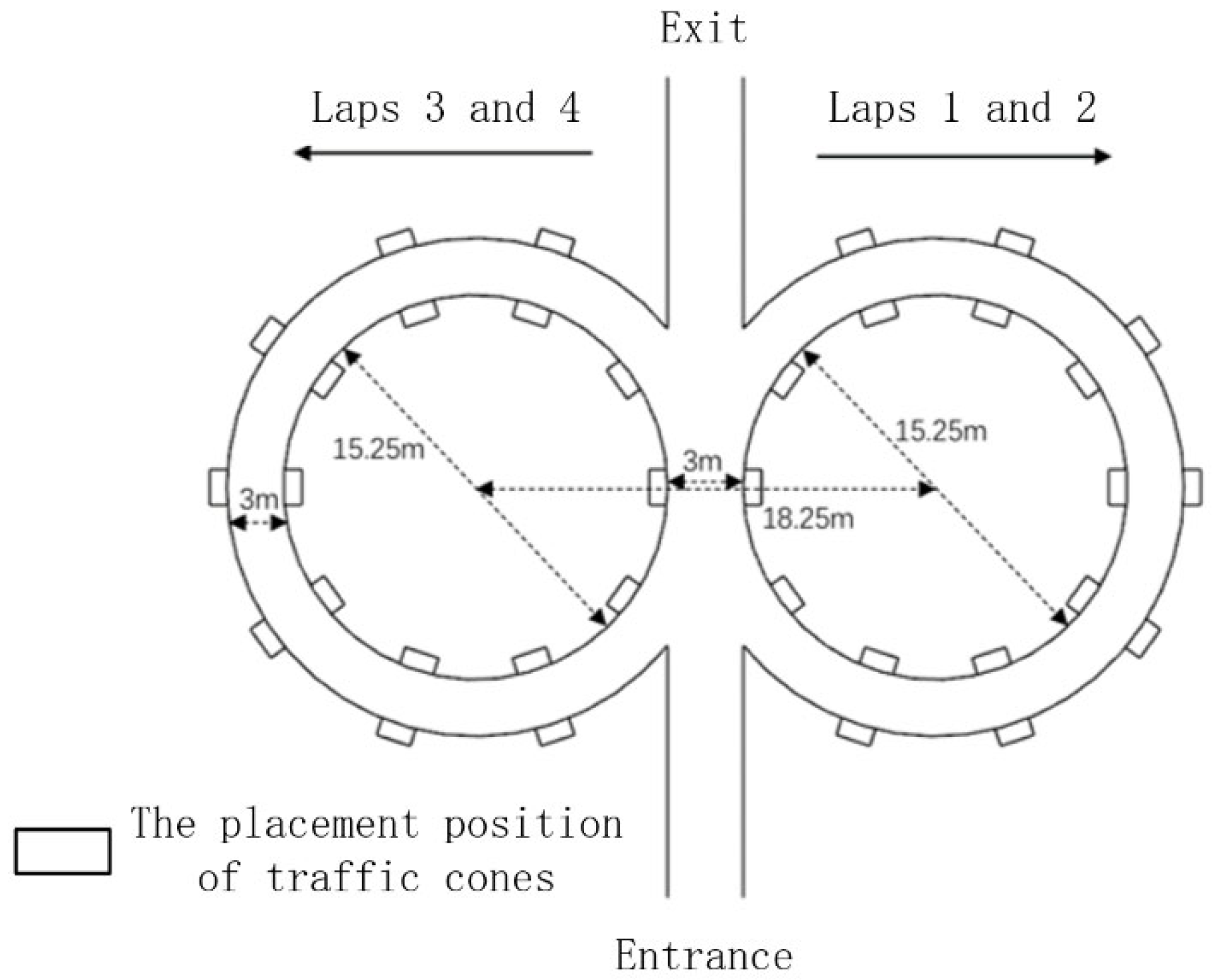
2.2.2. Figure-Eight Loop Condition

The track features a unique figure-eight design composed of two circular paths with equal radii, forming a continuous curved layout. This configuration not only evaluates the vehicle’s maneuverability under successive turns but also challenges driver skill and vehicle stability. The detailed dimensions and layout of the track are shown in Figure 3. Racers drive their cars two times around the right side and two times around the left side in order to complete the figure-eight loop.
The working condition is configured as follows: 15.25 m diameter closed circumferential roadway, with the coefficient of adhesion set to 0.8 and a static start motor with 3N∙m constant torque output.

3. Model Construction

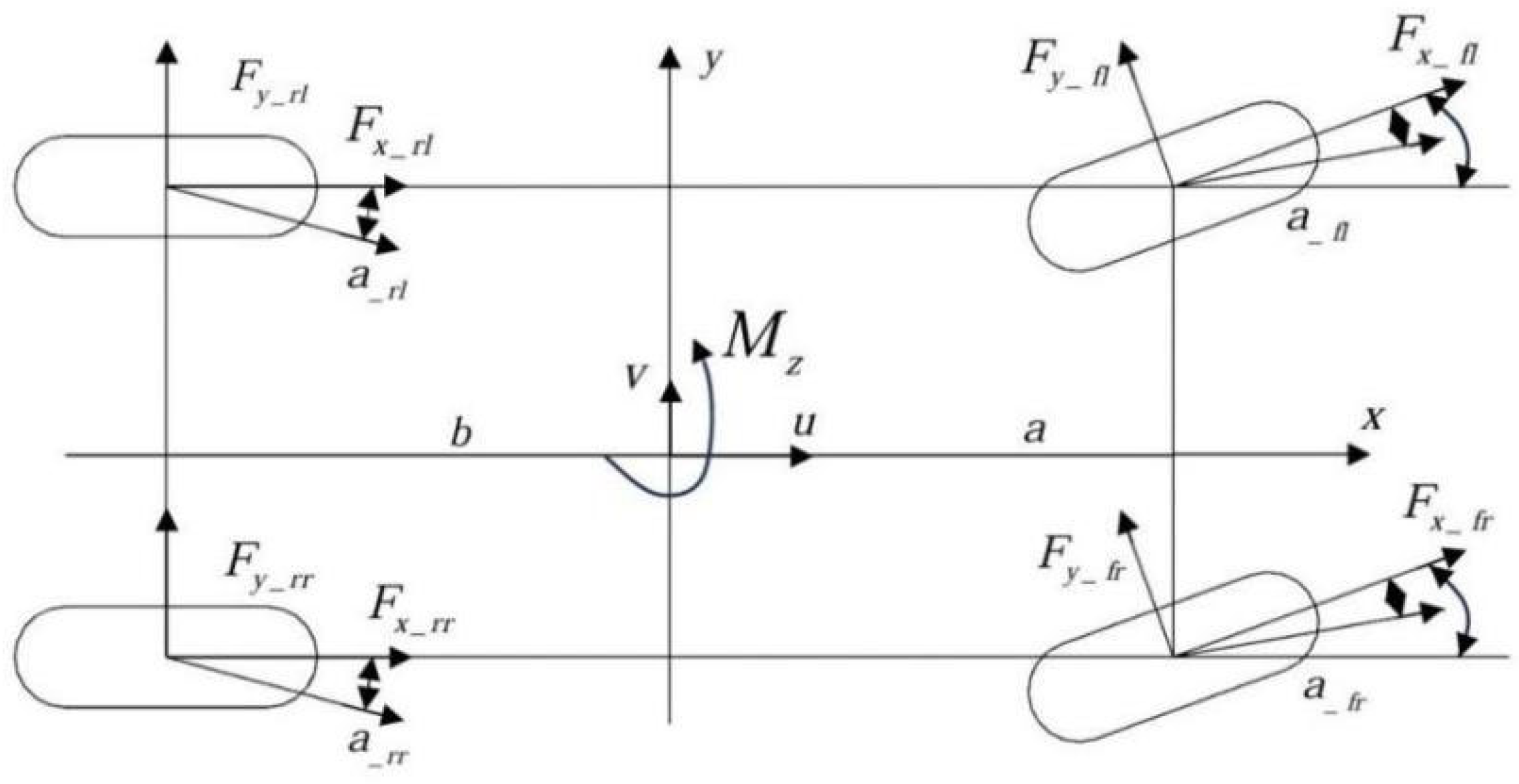
3.1. Estimation Model

To accurately simulate and estimate the dynamic states of a four-motor independently driven racing car, a three-degree-of-freedom vehicle dynamics model is introduced. The model is characterized by four state variables: lateral displacement, yaw angle, longitudinal displacement, and longitudinal velocity, enabling the analysis of vehicle stability, maneuverability, and ride comfort. It is designed to align with the control algorithm and the required input–output data, with the coordinate origin defined at the vehicle’s center of mass. The vehicle body is modeled as a rigid body with four independently controlled wheels [26], as illustrated in Figure 4.
The kinetic equations are shown in Equations (1)–(3).
u = a x + v r
v = a y + u r
r = 1 I z M Z
where ax is the longitudinal acceleration of the car, ay is the lateral acceleration of the car, u is the longitudinal speed, v is the lateral speed, r is the angular speed of the pendulum, Iz is the inertia around the axis, and Mz is the moment of the pendulum.
The longitudinal acceleration, lateral acceleration, and transverse moment of the racing car could be shown by Equations (4)–(6) [27].
a x = 1 m F x _ f l cos δ f l F y _ f l sin δ f l + F x _ f r cos δ f r F y _ f r sin δ f r + F x _ r l + F x _ r r
a y = 1 m F x _ f l sin δ f l F y _ f l cos δ f l + F x _ f r sin δ f r F y _ f r cos δ f r + F y _ r l + F y _ r r
M z = a F x _ f l sin δ f l + F y _ f l cos δ f l B 1 2 F x _ f l cos δ f l F y _ f l sin δ f l + a ( F x _ f r sin δ f r + F y _ f r cos δ f r ) + B 2 2 F x _ f r cos δ f r F y _ f r sin δ f r b ( F y _ r l + F y _ r r ) B 2 2 ( F x _ r l F x _ r r )
where Fx_fl, Fx_fr, Fx_rl, Fx_rr are the longitudinal forces on the four wheels of the racing car, Fy_fl, Fy_fr, Fy_rl, Fy_rr are the lateral forces on the four wheels, δfl, δfr, δrl, and δrr are the angles of rotation of the four wheels, and m is the total mass of the vehicle.

3.2. Drive Control Strategy Model

3.2.1. Straight-Line Acceleration Condition

Based on a detailed analysis of linear acceleration conditions and corresponding algorithm design, a baseline torque output module and a fuzzy PID-based regulating torque module are developed. To address potential inaccuracies in slip ratio measurements at low vehicle speeds, a control mechanism is implemented whereby the regulating module is deactivated below a predefined speed threshold, thereby enhancing system accuracy and reliability. The model takes key parameters such as four-wheel torque and motor speed as inputs. Following computational processing, the resulting driving force distribution for all four wheels under linear acceleration is illustrated in Figure 5.

3.2.2. Figure-Eight Loop Condition

To ensure stable speed and driving performance under the figure-eight loop condition, direct yaw moment control is employed as an effective strategy. This approach generates corrective torque by adjusting individual wheel outputs to enhance the vehicle’s maneuvering stability. Accordingly, the application of direct yaw moment control is investigated to improve steering performance under curved road conditions such as figure-eight trajectories. The Simulink model of the direct yaw moment control system is presented in Figure 6. Model inputs include front wheel angle, vehicle speed, sideslip angle at the center of mass, and yaw rate, while the calculated outputs correspond to the required torques for each of the four wheels. The integrated simulation framework is illustrated in Figure 7.

4. Validation of State Estimation

4.1. Straight-Line Acceleration Condition

Figure 8 presents the comparison between the estimated vehicle states obtained from the state estimation algorithm and the actual values generated by CarSim. The Actual Value means that the value is obtained directly from CarSim’s high-fidelity vehicle dynamics model, which serves as the “ground truth” benchmark. The Estimated Value means that the value is generated by our 3-DOF dynamics model (Section 3.1), which uses simplified equations to approximate vehicle states. Figure 8a illustrates the longitudinal velocity comparison. The vehicle undergoes continuous acceleration from 0 to 6 s. During the time, a certain deviation is observed between the estimated and actual values, although the two curves align closely at the simulation onset. As the simulation progresses, cumulative errors emerge, yet the overall trend remains consistent. The maximum deviation reaches approximately 5 km/h, which remains within acceptable limits, indicating satisfactory estimation accuracy of longitudinal velocity.
Figure 8b shows the lateral velocity comparison. The peak lateral speed of approximately 0.8 km/h is reached at around 3 s. Due to the absence of steering input during the experiment, both the estimated and actual lateral velocities fluctuate between 0 and 5 s. Although there are slight variations in the simulation that cause the curves to deviate slightly, the estimated values generally reflect the fluctuation range of the actual data. Given the relatively small magnitude of lateral velocity, the estimation deviation is considered negligible.
Figure 8c, Figure 8d, and Figure 8e display the comparisons of longitudinal acceleration, lateral acceleration, and yaw rate, respectively. In all cases, the estimated values closely match the CarSim outputs, confirming that the proposed estimation algorithm reliably captures key vehicle dynamic parameters under noise-free conditions.
In summary, Figure 8 demonstrates the estimation algorithm’s effect in estimating different vehicle motion parameters. Although there is a certain degree of error, in general, the error is within the acceptable range, reflecting that the estimation algorithm has good accuracy and reliability.

4.2. Figure-Eight Loop Condition

Figure 9 illustrates the comparison between the estimated vehicle states and the actual values obtained from CarSim under the figure-eight loop condition.
Figure 9a shows the longitudinal velocity comparison. The estimated and actual values closely match within the first 0–4 s, demonstrating accurate tracking by the estimation algorithm. As simulation time increases, a deviation of approximately 2 km/h emerges, though without significant error accumulation, indicating good robustness and accuracy of the longitudinal velocity estimation.
Figure 9b presents the lateral velocity comparison. The lateral speed reaches peak values of ±20 m/s twice. Despite fluctuations caused by the curved trajectory of the figure-eight path, the estimated values closely follow the actual values throughout the simulation.
Figure 9c displays the longitudinal acceleration comparison. A significant difference appears at around 1 s, which may be due to the sharp fluctuations in acceleration affecting the estimation of the transverse velocity. And the difference between the two values is around 0.4, which is within the acceptable range.
Figure 9d and Figure 9e show comparisons for lateral acceleration and yaw rate, respectively. Lateral acceleration oscillates around 0 m/s2, while yaw rate exhibits a gradual upward trend. In both cases, the estimated values align well with the CarSim outputs, confirming the accuracy and stability of the estimation algorithm.
In summary, Figure 9 verifies the effectiveness of the proposed estimation algorithm in capturing vehicle state information under the figure-eight loop condition. The longitudinal velocity estimation exhibits high robustness and accuracy. Although some error accumulation is observed in longitudinal acceleration estimation, the algorithm demonstrates self-correcting capability, allowing the estimated values to gradually converge toward the actual values over time.

5. Simulation Result

5.1. Straight-Line Acceleration Condition

In the 75 m linear acceleration condition, the road surface adhesion coefficient is set to 0.8. The comparison between the proposed driving strategy and the conventional control strategy is illustrated in Figure 10. Driving Strategy refers to our dual-mode control algorithm. General Drive Strategy denotes a baseline PID controller (representing conventional approaches in Formula Student teams) with fixed gains and no adaptive mode switching.
As shown in Figure 10, under the proposed drive strategy, the driving force of all four wheels initially peaks at 500 N during the startup phase. Because the car needs overcome static friction and the vehicle’s inertial longitudinal force, from the second onward, the force stabilizes at approximately 200 N, with minimal fluctuation observed throughout the remaining simulation period. The curves of all four wheels remain generally consistent, indicating uniform torque distribution. In contrast, under the conventional strategy, the driving force stabilizes at approximately 150 N between 2 and 6 s, with noticeable fluctuations occurring in the 0–1 s interval. The proposed strategy delivers significantly higher and more stable driving force throughout the straight-line acceleration condition.
Analysis of the comparison curves for each wheel in Figure 10a–d reveals that the proposed driving strategy demonstrates superior control capability compared to the conventional method, achieving steady-state operation more rapidly and effectively.
Figure 11 presents the slip ratio comparison between the proposed drive strategy and the conventional control strategy.
As shown, the conventional strategy exhibits a significantly higher slip ratio within the first second. This is primarily due to the asynchronous rotation of the drive and non-drive wheels during startup, where the drive wheels engage earlier, resulting in increased slip. Furthermore, anti-slip control is not activated at low vehicle speeds, rendering early slip correction ineffective.
Between 1 and 3 s, the slip ratio under the conventional strategy continues to exceed the optimal threshold of 20%, primarily due to excessive drive torque leading to wheel slip. In contrast, the proposed strategy maintains the slip ratio consistently around 18%, below the critical threshold, by dynamically adjusting motor output torque. This regulation ensures optimal tire-road adhesion and improved traction performance throughout the acceleration phase.
In summary, in the same experimental context, the drive control strategy is better than the conventional one, as it ensures good vehicle adhesion and higher acceleration.

5.2. Figure-Eight Loop Condition

Figure 12 illustrates the driving force comparison among the four wheels—left front, left rear, right front, and right rear—over a 6-s simulation period. The results indicate that all four wheels exhibit a similar variation trend in driving force throughout the test, reflecting balanced torque distribution and consistent dynamic response under the applied control strategy.
As shown in Figure 12, the driving forces of all four wheels remain approximately equal throughout the condition, indicating balanced force distribution and enhanced vehicle stability. During the initial 4 s, the driving force exhibits a rapid increase, reaching a peak of approximately 700 N. This could be attributed to the need to overcome static friction and the relatively large longitudinal inertial force at startup. As the vehicle transitions into a stable acceleration phase, the driving force gradually decreases between 4 and 6 s; 0 and 6 s are attributed to the complex demands of the figure-eight maneuver, which involves frequent cornering. During such conditions, the driving force required by each wheel varies due to differences in load transfer and traction demand. The proposed strategy dynamically adjusts torque distribution in real time, enhancing cornering performance and overall vehicle stability.
Figure 13 presents the comparison of center-of-mass lateral deflection between the proposed drive strategy and the conventional strategy under the figure-eight loop condition. The conventional strategy exhibits significant deviation, with a peak lateral deflection of 2°, exceeding the ±0.7° stability threshold. In contrast, the proposed strategy effectively constrains lateral deflection within the stability region, maintaining it around −0.3° between 3 s and 6 s. These results indicate that the proposed drive control strategy achieves superior regulation of center-of-mass lateral deflection compared to the conventional approach, thereby enhancing vehicle stability during complex cornering maneuvers.
Combined with Figure 12 and Figure 13, it is evident that, compared to the conventional control strategy, the proposed drive control strategy enhances vehicle stability during cornering by effectively suppressing oversteering and related instabilities. This enables the racing car to maintain greater stability while negotiating turns and simultaneously achieve the target speed more rapidly.

6. Discussion

Scholars both domestically and internationally have proposed various solutions for drive force distribution strategies, but no universal theoretical framework has yet been established. Hierarchical control [28] breaks down complex control tasks into decision-making and execution layers, facilitating team division of labor for development and debugging. However, communication delays between layers may cause response lag under dynamic conditions, affecting high-speed cornering performance. Model predictive control [29] could simultaneously optimize objectives such as torque distribution, energy efficiency, and yaw stability within a single framework, avoiding subsystem conflicts inherent in hierarchical control. However, it faces challenges in real-time debugging and modeling complexity. Fuzzy control [30] does not require precise mathematical models and exhibits strong robustness, but it lacks dynamic adaptability and necessitates extensive real-vehicle data to adjust membership functions.
The control strategy proposed in this paper fundamentally differs from or improves upon existing advanced control strategies in the following key ways. Firstly, unlike hierarchical or MPC methods that focus on single-objective optimization, the control strategy provided dynamically switches between two specialized control modes: Slip-ratio-based anti-slip control is good for longitudinal dynamics. Direct yaw moment control is good for lateral stability. This dual-mode design avoids the trade-offs inherent in single-strategy systems. Secondly, while prior work uses static fuzzy logic or PID, the control strategy integrates fuzzy PID with real-time slip ratio feedback to adjust torque distribution dynamically. Thirdly, unlike MPC, which solves optimization problems iteratively, the control strategy uses decentralized fuzzy PID modules for slip and yaw control. Finally, the proposed coordinated control strategy demonstrates distinct advantages in handling the Formula Student racing car’s extreme operating conditions. Compared to conventional PID control, the slip-ratio-based fuzzy PID achieves 18% peak slip ratio. The direct yaw moment control’s ability to stabilize sideslip angles at −0.3° (±0.7° threshold).
Beyond the immediate application to Formula Student racing cars, this study contributes to the broader development of adaptive control systems for electric vehicles in several important ways. First, the dual-mode control architecture demonstrates a practical framework for integrating longitudinal slip control and lateral stability management—a critical requirement for all high-performance EVs operating under variable road conditions. Second, the implementation of fuzzy PID control with real-time parameter adaptation provides insights into balancing computational efficiency with control precision, which is particularly relevant for production EVs with embedded system constraints. While the current study focused on racing-specific scenarios, the core methodology could be extended to address common challenges in consumer EVs, such as low-friction road handling and emergency maneuver stability. However, three key limitations emerge:
(1) The 3-DOF model’s neglect of vertical dynamics reduces prediction accuracy on uneven surfaces, particularly affecting the slip ratio controller during suspension travel;
(2) Real-world implementation would face challenges from motor delay effects (≈50 ms) not modeled in the ideal Simulink environment, potentially degrading response times by 15–20%;
(3) The strategy’s energy efficiency remains unoptimized, as torque distribution prioritizes stability over power consumption.

7. Conclusions

The following conclusions are drawn to address the specialized operational requirements of a four-wheel independently driven electric racing car in the Formula Student Electric Competition:
(1) A vehicle state estimation algorithm based on a three-degree-of-freedom dynamic model is developed and validated through simulation. The results demonstrate high robustness and accuracy under both straight-line acceleration and figure-eight loop conditions, providing a theoretical foundation for driving force allocation optimization.
(2) A coordinated fuzzy control strategy is implemented and validated on the CarSim–Simulink. Under the straight-line acceleration condition, the slip-ratio-based fuzzy PID control strategy effectively constrained the maximum slip ratio within the optimal range of 18%. Under the figure-eight loop condition, the direct yaw moment control strategy maintained the lateral deflection angle of the center of mass around −0.3°, thereby enhancing lateral stability.
The development of a lightweight, real-time capable solution is prioritized in this study to meet the stringent computational and latency constraints of Formula Student racing scenarios. While more sophisticated methods could further improve performance, the proposed dual-mode strategy achieves a practical balance between computational efficiency and control accuracy, ensuring deployability on embedded systems with limited resources. The control framework will be directly implemented using code generated from Simulink, with the 3-degree-of-freedom vehicle model serving as a real-time observer for state estimation, while wheel speed and steering angle signals dynamically trigger the dual-mode strategy.
In the future, further analysis is still needed for other racing conditions, such as endurance races. At the same time, the controller has strong adaptability to changes in the friction coefficient μ between 0.3 and 0.9, confirming its flexibility under different track conditions. However, further testing is still needed under extremely low friction coefficient conditions (μ < 0.2), which are common in wet weather races.

Author Contributions

Y.B.: Funding acquisition, Conceptualization, Supervision, Writing–original draft. W.K.: Methodology, Software, Validation, Writing—original draft. L.Z.: Data curation, Software, Writing—review and editing. W.Z.: Data curation, Software, Writing—review and editing. C.Z.: Visualization, Writing—review and editing. S.C.: Formal Analysis, Investigation, Writing–review and editing. All authors have read and agreed to the published version of the manuscript.

Funding

The authors declare that financial support was received for the research, authorship, and/or publication of this article. This research presented in this paper was conducted with the support of the National Natural Science Foundation of Jiangsu Province, grant number BK20220685; Qing Lan Project, grant number Su teacher letter [2024] No. 14; the National Key Laboratory of Automotive Chassis Integration and Bionics, grant number 20211205; Key Research and Development Program of Jiangsu Province, grant number BE2022146.

Data Availability Statement

The raw data supporting the conclusions of this article will be made available by the authors without undue reservation.

Conflicts of Interest

The authors declare that the research was conducted in the absence of any commercial or financial relationships that could be construed as a potential conflict of interest.

References

  1. Niu, S.; Yu, H.; Niu, S.; Jian, L. Power loss analysis and thermal assessment on wireless electric vehicle charging technology: The over-temperature risk of ground assembly needs attention. Appl. Energy 2020, 275, 115344. [Google Scholar] [CrossRef]
  2. Wang, J.; Zhang, C.; Yang, Z.; Dang, M.; Chang, B.; Li, C.; Zhang, R.; Ma, J. Hierarchical driving force allocation strategy for 4-WID electric vehicles. Proc. Inst. Mech. Eng. Part D J. Automob. Eng. 2023, 237, 2484–2498. [Google Scholar] [CrossRef]
  3. Zhai, L.; Wang, C.; Hou, Y.; Hou, R.; Ming Mok, Y.; Zhang, X. Two-level optimal torque distribution for handling stability control of a four hub-motor independent-drive electric vehicle under various adhesion conditions. Proc. Inst. Mech. Eng. Part D J. Automob. Eng. 2023, 237, 544–559. [Google Scholar] [CrossRef]
  4. Peng, H.; Wang, W.; Xiang, C.; Li, L.; Wang, X. Torque coordinated control of four in-wheel motor independent-drive vehicles with consideration of the safety and economy. IEEE Trans. Veh. Technol. 2019, 68, 9604–9618. [Google Scholar] [CrossRef]
  5. Zou, Y.; Zhang, Y.; Yang, Y. Multi-perspective evaluation of a novel powertrain integrating series-parallel and power-split modes: An ultra-rapid hierarchical control approach. Mech. Mach. Theory 2025, 210, 106034. [Google Scholar] [CrossRef]
  6. Chen, L.; Liao, Z.; Zhang, Z. Design of Hierarchical Control System for Dual-steering of Multi-wheel Distributed Electric Drive Vehicles. Automot. Eng. 2021, 43, 1383–1393. [Google Scholar] [CrossRef]
  7. Mirzaei, M.; Vali, R.A.; Allahverdizadeh, F.; Behnamgol, V. Fixed-time dynamic control allocation for the distribution of braking forces in a vehicle ESC system. Nonlinear Dyn. 2024, 112, 22009–22037. [Google Scholar] [CrossRef]
  8. Ao, D.; Wong, K.P.; Huang, W. Model predictive control allocation based on adaptive sliding mode control strategy for enhancing the lateral stability of four-wheel-drive electric vehicles. Proc. Inst. Mech. Eng. Part D J. Automob. Eng. 2024, 238, 1514–1534. [Google Scholar] [CrossRef]
  9. Zha, Y.; Quan, X.; Ma, F.; Liu, G.; Zheng, X.; Yu, M. Stability control for a four-wheel-independent-drive electric vehicle based on model predictive control. SAE Int. J. Veh. Dyn. Stab. NVH 2021, 5, 191–204. [Google Scholar] [CrossRef]
  10. Qi, G.; Yue, M.; Shangguan, J.; Guo, L.; Zhao, J. Integrated control method for path tracking and lateral stability of distributed drive electric vehicles with extended Kalman filter–based tire cornering stiffness estimation. J. Vib. Control 2024, 30, 2582–2595. [Google Scholar] [CrossRef]
  11. Zhang, C.; Zhang, D.; Wang, R.; Zhang, R.; Wen, J. Stability control strategy for in-wheel-motor-drive electric vehicle based on dspace. Mechatron. Syst. Control 2020, 48, 134–143. [Google Scholar] [CrossRef]
  12. Sankhwar, P. Application of Permanent Magnet Synchronous Motor for Electric Vehicle. Indian J. Des. Eng. 2024, 4, 1–6. [Google Scholar] [CrossRef]
  13. Zhang, J.; Li, C.Q.; Jia, Q.; Gao, R. Research on the Adaptive PID speed control method for Hub Motors. Mob. Inf. Syst. 2022, 2022, 4979824. [Google Scholar] [CrossRef]
  14. Jabari, M.; Rad, A. Optimization of speed control and reduction of torque ripple in switched reluctance motors using metaheuristic algorithms based PID and FOPID controllers at the edge. Tsinghua Sci. Technol. 2025, 30, 1526–1538. [Google Scholar] [CrossRef]
  15. Hasan, M.W.; Mohammed, A.S.; Noaman, S.F. An adaptive neuro-fuzzy with nonlinear PID controller design for electric vehicles. IFAC J. Syst. Control 2024, 27, 110238. [Google Scholar] [CrossRef]
  16. Silva, F.; Silva, L.; Eckert, J.J.; Yamashita, R.Y.; Lourenço, M.A. Parameter influence analysis in an optimized fuzzy stability control for a four-wheel independent-drive electric vehicle. Control Eng. Pract. 2022, 120, 115000. [Google Scholar] [CrossRef]
  17. Chen, Z.; Chen, C.; Chen, B.; Fu, J.H. Research on Optimal Distribution Control Strategy of 4WID Electric Vehicle Torque. Mach. Des. Manuf. 2020, 12, 50–54. [Google Scholar] [CrossRef]
  18. Wang, J.; Gao, S.; Wang, K.; Wang, Y.; Wang, Q. Wheel torque distribution optimization of four-wheel independent-drive electric vehicle for energy efficient driving. Control Eng. Pract. 2021, 111, 114779. [Google Scholar] [CrossRef]
  19. Liu, H.; Li, X.; Wang, W.; Han, L.; Xin, H.; Xiang, C. Adaptive equivalent consumption minimisation strategy and dynamic control allocation-based optimal power management strategy for four-wheel drive hybrid electric vehicles. Proc. Inst. Mech. Eng. Part D J. Automob. Eng. 2019, 233, 3125–3146. [Google Scholar] [CrossRef]
  20. Yao, Y.; Li, E.; Peng, C. Research on the distribution strategy of longitudinal driving force of vehicle driven by 8 × 8 in-wheel motors. J. Phys. Conf. Ser. 2022, 2181, 012017. [Google Scholar] [CrossRef]
  21. Patel, M.; Mahajan, M. Modeling and simulation of vehicle behavior for design and tuning of electronic differential for formula student vehicle. In Proceedings of the International Design Engineering Technical Conferences and Computers and Information in Engineering Conference, Charlotte, NC, USA, 21–24 August 2016; Volume 50138, p. V003T01A011. [Google Scholar] [CrossRef]
  22. Adnane, M.; Nguyen, C.T.P.; Khoumsi, A.; Trovão, J.P.F. Real-time torque-distribution for dual-motor off-road vehicle using machine learning approach. IEEE Trans. Veh. Technol. 2024, 73, 4567–4577. [Google Scholar] [CrossRef]
  23. Halimi, H.; Elgarouaz, M.; Lazrak, L.; El Daoudi, S. Experimental Validation of an Open Loop Drive Control of an Asynchronous Motor with the TMS320F28379D DSP Card and Speed Senser. Results Eng. 2025, 26, 105116. [Google Scholar] [CrossRef]
  24. Saputra, D.; Ma’arif, A.; Maghfiroh, H.; Chotikunnan, P.; Rahmadhia, S.N. Design and application of PLC-based speed control for DC motor using PID with identification system and MATLAB tuner. Int. J. Robot. Control Syst. 2023, 3, 233–244. [Google Scholar] [CrossRef]
  25. Oubelaid, A.; Mohamed, N.; Rathore, R.S.; Bajaj, M.; Rekioua, T. Artificial Neural Networks-Based Torque Distribution for Riding Comfort Improvement of Hybrid Electric Vehicles. Procedia Comput. Sci. 2024, 235, 1300–1309. [Google Scholar] [CrossRef]
  26. Lin, F.; Cai, Y.; Zhao, Y.; Zang, L.; Wang, S. Lateral Stability Control of Distributed Drive Electric Vehicle with Mechanical Elastic Wheel. J. Mech. Eng. 2022, 58, 236–243. [Google Scholar] [CrossRef]
  27. Zhao, M.; Guo, H.; Zhang, L.; Liu, X. Driving stability control of four-wheel independent steering distributed drive electric vehicle with single-wheel steering failure. J. Mech. Eng. 2024, 60, 507–522. [Google Scholar] [CrossRef]
  28. Zhang, H.; Liang, H.; Tao, X.; Ding, Y.; Yu, B.; Bai, R. Driving Force Distribution and Control for Maneuverability and Stability of a 6WD Skid-Steering EUGV with Independent Drive Motors. Appl. Sci. 2021, 11, 961. [Google Scholar] [CrossRef]
  29. Xu, X.; Wang, K.; Li, Q.; Yang, J. An Optimal Hierarchical Control Strategy for 4WS-4WD Vehicles Using Nonlinear Model Predictive Control. Machines 2024, 12, 84. [Google Scholar] [CrossRef]
  30. Yin, Z.; Ma, X.; Su, R.; Huang, Z.; Zhang, C. Regenerative Braking of Electric Vehicles Based on Fuzzy Control Strategy. Processes 2023, 11, 2985. [Google Scholar] [CrossRef]
Figure 1. System of Formula Student electric racing car. (a) Racing car assembly breakdown diagram; (b) Racing car thermal management diagram.
Wevj 16 00421 g001
Figure 2. Straight-line acceleration track map.
Wevj 16 00421 g002
Figure 3. Figure-eight loop map.
Wevj 16 00421 g003
Figure 4. Three-degree-of-freedom estimation model.
Wevj 16 00421 g004
Figure 5. Simulink model construction.
Wevj 16 00421 g005
Figure 6. Simulink transverse moment model construction.
Wevj 16 00421 g006
Figure 7. The driving control for the figure-eight loopring condition model construction.
Wevj 16 00421 g007
Figure 8. Comparison curve of vehicle driving status in straight-line acceleration condition. (a) Racing longitudinal speed curve; (b) Racing lateral speed curve (c) Racing longitudinal acceleration curve; (d) Racing lateral acceleration curve; (e) Racing transverse pendulum angular velocity curve.
Wevj 16 00421 g008
Figure 9. Comparison curve of vehicle driving status in figure-eight loop condition. (a) Racing longitudinal speed curve; (b) Racing lateral speed curve; (c) Racing longitudinal acceleration curve; (d) Racing lateral acceleration curve; (e) Racing transverse pendulum angular velocity curve.
Wevj 16 00421 g009
Figure 10. Racing driving force graph in straight-line acceleration condition. (a) Left front wheel longitudinal force curve; (b) Left rear wheel longitudinal force curve; (c) Right front wheel longitudinal force curve; (d) Right rear wheel longitudinal force curve.
Wevj 16 00421 g010
Figure 11. Slip ratio comparison curve.
Wevj 16 00421 g011
Figure 12. Racing driving force graph in figure-eight loop condition. (a) Left front wheel longitudinal force curve; (b) Left rear wheel longitudinal force curve; (c) Right front wheel longitudinal force curve; (d) Right rear wheel longitudinal force curve.
Wevj 16 00421 g012
Figure 13. Comparison curve of mass center side deflection angle.
Wevj 16 00421 g013
Table 1. Parameters of racing car and motor.
Parameter NameUnitValueParameter NameUnitValue
Vehicle parameters
Vehicle weightkg250Wheelbasemm1600
Distance from center of mass to front axlemm879.31Center of mass heightmm229.46
Overall widthmm1402Overall heightmm1190
Front wheelbasemm1212Rear wheelbasemm1212
Spring loaded masskg150Front/rear load ratio/48:52
Windward aream21.23Left/Right load ratio/1:1
Steering arm lengthmm90Tire radiusmm205
Front and rear tire width ratio/1Steering ratio/4:1
Inclination angle of main pindeg5Main pin rear camber angledeg5
Front wheel camberdeg−5Front wheel front beam angledeg−5
Motor parameters
Motor masskg12Rated powerkW40
Shaft length/mmmm86Peak powerkW109
Housing diameter/mmmm228Continuous powerkW62
Peak torqueN·m230Peak speedrpm6000
Continuous torqueN·m120Efficiency%92–98
Motor masskg12Rated powerkW40
Shaft lengthmm86Peak powerkW109
Housing diametermm228Continuous powerkW62
Battery parameters
Battery pack sizemm3474.6 × 618.2 × 168.4Battery pack-type Serial connection
Energy capacitykWh7.84
Disclaimer/Publisher’s Note: The statements, opinions and data contained in all publications are solely those of the individual author(s) and contributor(s) and not of MDPI and/or the editor(s). MDPI and/or the editor(s) disclaim responsibility for any injury to people or property resulting from any ideas, methods, instructions or products referred to in the content.

