Article

Sliding Mode Thrust Control Strategy for Electromagnetic Energy-Feeding Shock Absorbers Based on an Improved Gray Wolf Optimizer

School of Transportation and Vehicle Engineering, Shandong University of Technology, Zibo 255000, China
*
Author to whom correspondence should be addressed.
World Electr. Veh. J. 2025, 16(7), 366; https://doi.org/10.3390/wevj16070366
Submission received: 14 May 2025 / Revised: 22 June 2025 / Accepted: 30 June 2025 / Published: 2 July 2025

Abstract

Owing to its high energy efficiency, regenerative capability, and fast dynamic response, the Electromagnetic Energy-Feeding Shock Absorber has found widespread application in automotive suspension control systems. To further improve thrust control precision, this study presents a sliding mode thrust controller designed using an improved Gray Wolf Optimization algorithm. Firstly, an improved exponential reaching law is adopted, where a saturation function replaces the traditional sign function to enhance system tracking accuracy and stability. Meanwhile, a position update strategy from the particle swarm optimization (PSO) algorithm is integrated into the gray wolf optimizer (GWO) to improve the global search ability and the balance of local exploitation. Secondly, the improved GWO is combined with sliding mode control to achieve online optimization of controller parameters, ensuring system robustness while suppressing chattering. Finally, comparative analyses and simulation validations are conducted to verify the effectiveness of the proposed controller. Simulation results show that, under step input conditions, the improved GWO reduces the rise time from 0.0034 s to 0.002 s and the steady-state error from 0.4 N to 0.12 N. Under sinusoidal input, the average error is reduced from 0.26 N to 0.12 N. Under noise disturbance, the average deviation is reduced from 2.77 N to 2.14 N. These results demonstrate that the improved GWO not only provides excellent trajectory tracking and control accuracy but also exhibits strong robustness under varying operating conditions and random white noise disturbances.

1. Introduction

The Electromagnetic Energy-Feeding Shock Absorber (EEFS) simplifies mechanical design by eliminating motion conversion mechanisms, thereby providing advantages such as high efficiency, energy savings, compact structure, and rapid dynamic response. These features have led to their widespread application in fields such as automotive systems, aerospace engineering, and modern machine tools [1]. Developing a high-performance control strategy for EEFS systems requires an accurate dynamic model of the actuator, particularly one that accounts for the nonlinear friction effects that emerge under low-speed and small-displacement operating conditions. These nonlinearities have a pronounced impact on thrust tracking accuracy and overall system stability. Building upon this model, a robust control scheme must be established to effectively manage internal uncertainties and external disturbances. However, due to the absence of intermediate mechanical components, EEFS is more directly exposed to internal and external disturbances, which, despite improving system accuracy, also pose greater challenges for system stability and control [2]. As a result, achieving precise thrust control has become a key research focus in EEFS control strategies [3]. In order to achieve this goal, precise system modeling, intelligent controller design, and simulation-based validation jointly establish a comprehensive framework for advancing thrust control in EEFS applications.
In recent years, extensive research efforts have been dedicated to improving the control performance of EEFS systems. A variety of control strategies have been explored, including proportional–integral–derivative (PID) control [4], active disturbance rejection control (ADRC) [5], adaptive control [6], optimal control [7], Deep Reinforcement Learning (DRL) [8], Model Predictive Control (MPC) [9], and sliding mode control (SMC) [10]. For instance, ref. [11] proposed a hybrid control scheme combining SMC and ADRC. This approach adopts a switching control mechanism in the outer position loop: SMC is applied when the system operates far from the sliding surface to achieve a fast dynamic response, while ADRC is activated near the sliding surface to effectively suppress chattering. This combined strategy significantly enhances both system stability and control accuracy. In [12], a modified reaching law was introduced into the SMC framework for clamping force regulation, leading to improved response performance. However, the method’s robustness remained limited. In another study [13], an adaptive SMC scheme was developed, incorporating friction model identification and compensation, which further improved tracking robustness.
Owing to its strong robustness against model uncertainties and external disturbances, as well as its ability to achieve fast convergence through careful design of the sliding surface and reaching law, SMC has been widely applied in various electromechanical systems.
Nevertheless, conventional SMC often relies on empirically tuned parameters, which not only limits its control potential but also results in significant development time and effort. To overcome this limitation, intelligent optimization algorithms have garnered increasing attention due to their ability to automate the parameter tuning process [14]. With ongoing advancements in intelligent control, a wide range of optimization algorithms, such as particle swarm (PSO) [15], neural networks [16], ant colony optimization (ACO) [17], genetic algorithms (GA) [18], whale optimization algorithm (WOA) [19], and GWO [1], have been introduced and successfully applied across various engineering domains.
Although SMC exhibits strong robustness and disturbance rejection capabilities in EEFS applications, the traditional approach suffers from parameter dependency and high-frequency chattering due to discontinuous control actions, leading to increased steady-state errors and degraded tracking accuracy [20]. To overcome these limitations, this paper proposes an improved sliding mode reaching law based on an integral sliding mode controller, enabling faster and more precise system response. Furthermore, an enhanced gray wolf optimizer is developed by incorporating the velocity update mechanism of PSO, thereby improving global search performance and enabling more efficient controller parameter optimization. This integrated approach aims to provide a novel and effective solution for high-precision thrust tracking control in electromagnetic energy-feeding damping systems. Given the unique design of the proposed EEFS system and the specific thrust control objectives addressed in this study, no directly comparable benchmarks are currently available in the literature. Consequently, the evaluation relies on internal comparisons under identical conditions to demonstrate the relative advantages of the proposed approach.

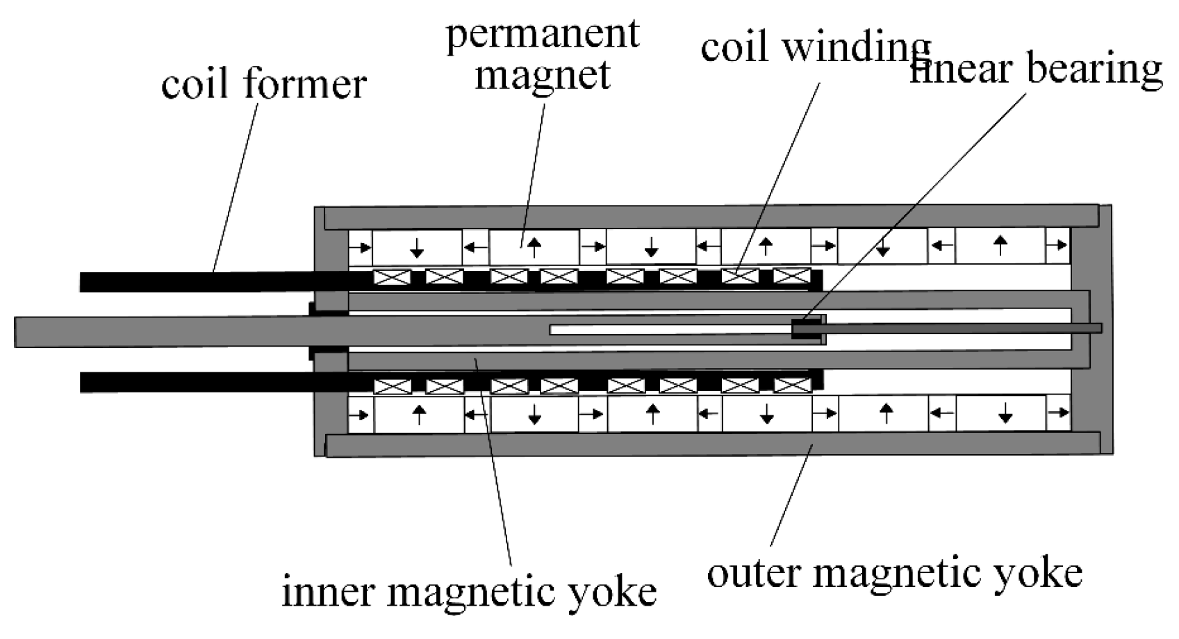
2. Mathematical Model of the Electromagnetic Energy-Feeding Shock Absorber

This study focuses on an EEFS, which primarily consists of a permanent magnet, coil windings, inner and outer magnetic yokes, and a coil frame [21]. The permanent magnet and magnetic yokes constitute the stator, while the coil windings wound around the coil frame form the mover. The structural configuration of the EEFS is illustrated in Figure 1.
The EEFS is a complex system characterized by electromechanical and magnetic coupling. Therefore, it is essential to establish mathematical models for its electrical, magnetic, and mechanical subsystems separately. The state-space representation of the EEFS can be expressed as follows:
d i ( t ) d t = R L i K e L v + U L v ˙ = F f cv M + K m M i x ˙ = v
where: U is the supply voltage; R is the total resistance of the coil; L is the total inductance of the coil; i is the current through the coil; v is the velocity of the moving coil (mover); K e is the back electromotive force (EMF) constant; K m is the electromagnetic force constant; M is the mass of the mover; x ˙ is the velocity of the mover; F f is the friction force. c is the damping coefficient.
The EEFS adopts a LuGre dynamic friction model, which is mathematically expressed as follows:
F f = σ 0 z + σ 1 d z d t + σ 2 v d z d t = v v g ( v ) z σ 0 g ( v ) = F C + ( F S - F C ) e ( v / v s ) 2
where: σ 0 is the stiffness coefficient; σ 1 is the micro-damping coefficient; z is the average deflection of the bristles on the contact surface; σ 2 is the viscous friction coefficient; v S is the Stribeck velocity; g ( v ) is a positive definite function used to describe the Stribeck effect; F c is the Coulomb friction force; F s is the static friction force.

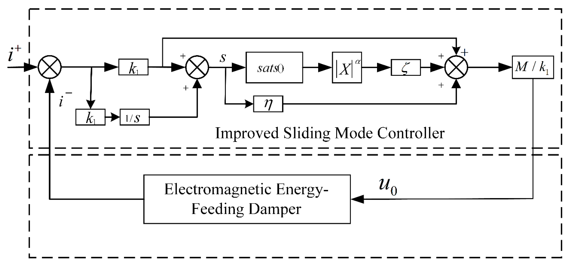
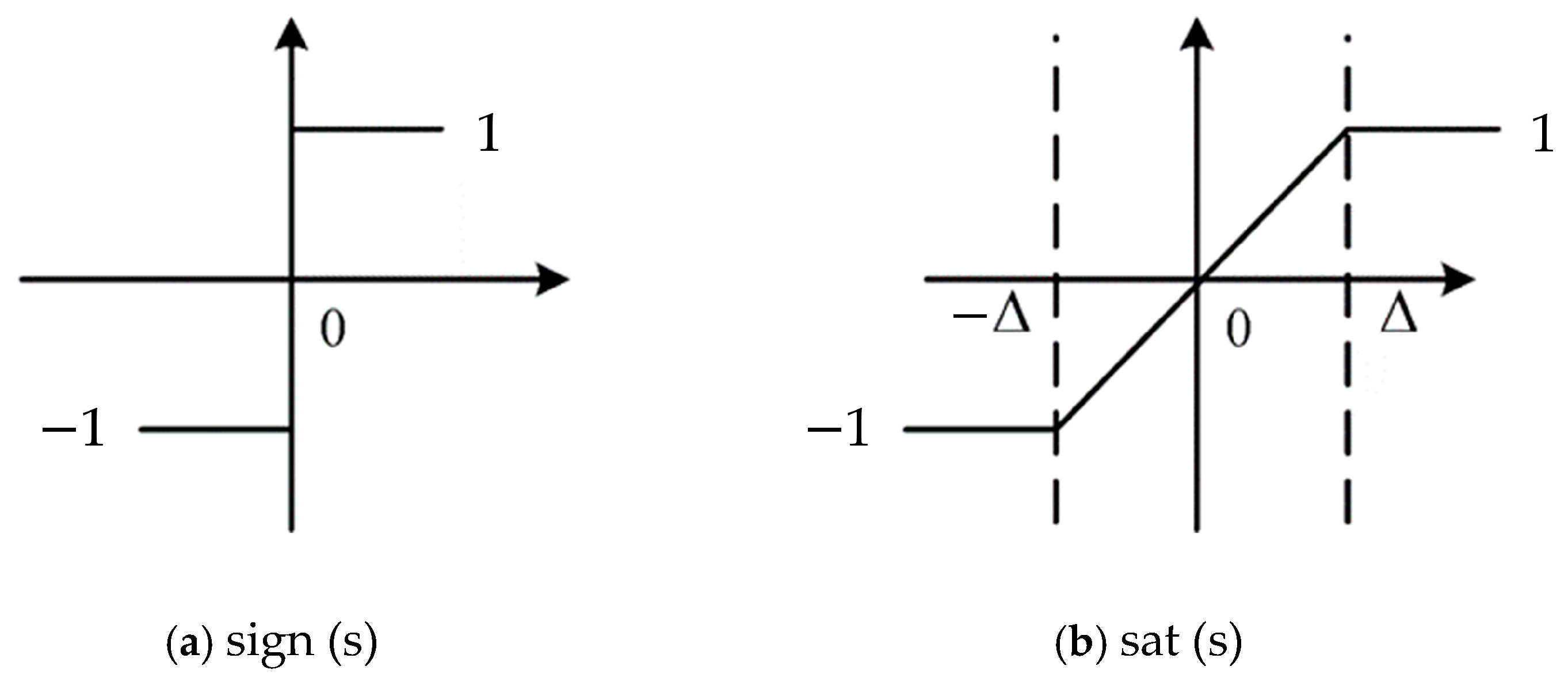
3. Improved Sliding Mode Thrust Controller Design

To significantly enhance the current response speed and eliminate overshoot, a nonlinear integral sliding surface is employed in this paper to optimize the system’s dynamic performance. In conventional sliding mode control, high-frequency chattering is commonly observed due to the inherent discontinuity of the switching control. To address this issue, an improved exponential reaching law is developed, in which a saturation function is used to replace the conventional sign function, thereby reducing the discontinuity of the input signal. Owing to the smooth transition characteristic of the saturation function during the reaching phase, this approach effectively mitigates high-frequency oscillations in the system, improving both tracking accuracy and overall stability [22]. The fundamental structure of the sliding mode thrust tracking controller is shown in Figure 2, which consists of two main components: the integral sliding surface and the improved reaching law.
In the design of the current control loop, the model of the EEFS is simplified, leading to the following expression:
F = K m i F f F d d i d t = R i L K e v L + U L d 2 x d t 2 = K m i M F f M F d M
Based on the second-order model of the EEFS described in Equation (3), the differential equation for the output error of the current control loop is defined as follows:
e i = i * i
where: F f is the friction force; F d is the external disturbance; K m is the electromagnetic force constant; K e is the back electromotive force (EMF) constant; i is the input current; i * is the desired input thrust; F is the actual thrust of the EEFS.
To address the steady-state error or instability that may arise under external disturbances in conventional sliding mode control, an integral term of the tracking error is introduced into the standard linear sliding surface. By appropriately selecting the initial conditions, the improved integral sliding mode controller contains only the sliding term, thereby avoiding the drawbacks of the traditional reaching phase in sliding mode control. The designed integral sliding surface is given by:
s = k 1 e I + k 2 0 τ e I d t
where k 1 and k 2 are the gain coefficients of the controller.
When the system state trajectory enters the sliding mode dynamic region, we have s = s ˙ = 0 . Taking the derivative of the sliding surface, we obtain:
s ˙ = k 1 e ˙ i + k 2 e i = k 1 ( d i d t ) + k 2 e i = k 1 ( R i L K e v L + U L ) + k 2 e f
The general expression for the exponential reaching law is given by:
s ˙ = ξ sgn ( s ) η s , ε > 0 , η > 0
where ξ and η are the switching control gains.
To meet the high dynamic response requirements of the current control loop and overcome the limitations of traditional exponential reaching law-based sliding mode control—particularly the chattering observed during the sliding phase—the discontinuous sign function sign(s) employed in switching control has been identified as a primary source of chattering. This phenomenon often induces high-frequency oscillations during actual actuator operation, thereby degrading control accuracy and increasing energy consumption [23].
Therefore, considering the practical demands of the actuator unit under complex operating conditions, the sliding mode thrust controller employs a saturation function sat(s) to replace the sign function sign(s), and the exponential reaching law is optimized to attenuate chattering. Based on the use of sat(s), the switching effect of the discontinuous input is mitigated. Additionally, a power function of the position error state variable is introduced to ensure that the exponential term gradually approaches zero as the system nears the sliding surface, thereby controlling the reaching velocity. In this case, the speed of the reaching motion depends on ξ X α s a t ( x ) .
The expression of the saturation function is given by:
s a t ( x ) = 1 x > Δ x Δ x Δ 1 x < Δ
where Δ is the boundary layer thickness, which is typically small but greater than zero.
A schematic comparison between the sign function and the saturation function is shown in Figure 3.
Based on the analysis of the conventional exponential reaching law, an improved exponential reaching law is proposed to further enhance the dynamic performance and robustness of the control system, as given by the following equation:
s ˙ = ξ X α s a t ( x ) η s lim t X = 0 , ξ > 0 , η > 0 , α > 0
the value of X can vary, for example e I , e ˙ I , or s , indicating that X is closely related to the state variable. With the introduction of X , the convergence speed of the system toward stability becomes dependent on the state. When the system state is far from the sliding surface, the value of X is relatively large, and the system approaches the sliding surface according to the rates of ξ X α s a t ( x ) and η s . Compared to the conventional reaching law, this leads to a faster convergence rate. When the system state is close to the sliding surface, η s approaches zero, and the ξ X α s a t ( x ) term dominates the convergence behavior. This reaching law ensures that the state variable quickly and smoothly converges to the origin and stabilizes, effectively suppressing chattering and enhancing the dynamic performance of the system.
Based on the proposed exponential reaching law, the voltage control law is derived as follows:
u = R i + K e v + L k 1 ( ξ X α s a t ( x ) + η s + k 2 e i )

Stability Analysis

Considering that the actuator unit is often subjected to internal and external disturbances, sensor noise, and other uncertainties during the sliding mode motion, the stability of the proposed sliding mode reaching law is analyzed in this section. To this end, the Lyapunov stability theorem is employed. Based on the selected sliding surface of the sliding mode controller, the Lyapunov function is defined as:
V = s 2 2
Taking the derivative of the above equation yields:
V ˙ = s s ˙ = s ( ξ X α s a t ( x ) η s ) = ξ X α s a t ( x ) s η s 2 < 0
when η > ξ > 0 , s 0 , ξ X α s a t ( x ) < 0 ,   η s 2 < 0 it follows that V ˙ < 0 , which implies that the system is asymptotically stable. Similarly, when s < 0 , it can be obtained that V ˙ < 0 as well. Therefore, it can be concluded that the proposed sliding mode control law ensures system stability.

4. Improved Gray Wolf Optimizer Design

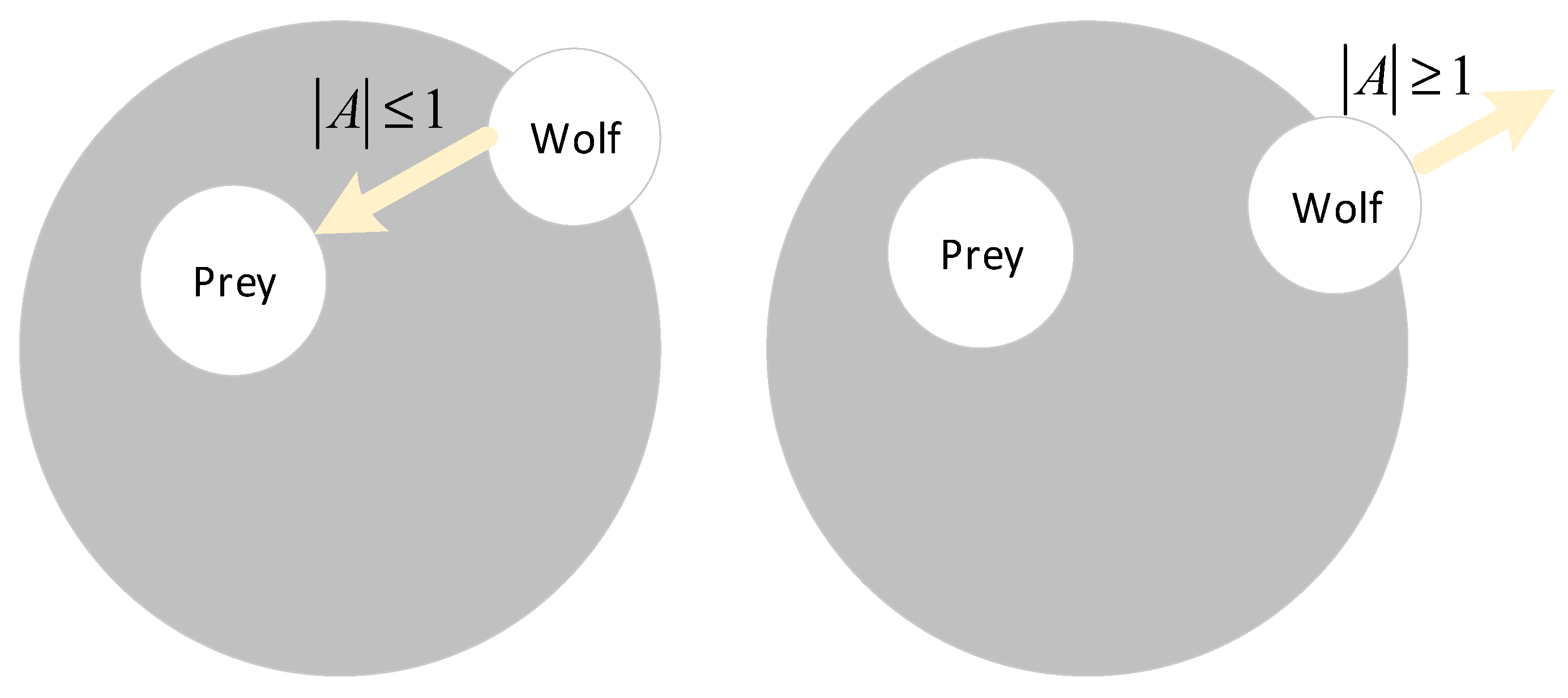
4.1. Basic Principles of the Gray Wolf Optimizer

The Gray Wolf Optimizer proposed by Mirjalili et al. in 2014 [24], is a metaheuristic optimization algorithm. In this algorithm, the prey represents the optimal solution, while the position of each gray wolf corresponds to a potential solution. The GWO employs a search mechanism similar to other intelligent algorithms. The gray wolf population typically consists of four categories: α , β , δ , and ω wolves. The α wolf acts as the leader of the entire population and holds the highest authority, making key decisions for the group. The β wolf has the second-highest rank, forming the decision-making core and assisting the α in population management. The δ wolves follow the leadership of α and β , and are responsible for tasks such as scouting, hunting, and guarding, serving as the main force of the pack. The ω wolves maintain the population dynamics and assist when the leading wolves fall into local optima.
The GWO algorithm consists of three main phases: searching, encircling, and attacking the prey. Initially, a population of gray wolves is randomly distributed in the search space. A convergence factor, along with coefficient vectors A and C, are then defined. These parameters are dynamically adjusted during iterations to balance exploration and exploitation. Each individual’s quality is evaluated using a fitness function, and the top three candidates with the best fitness values are selected as leaders ( α , β , δ ,). These leaders guide the rest of the population in the search for the global optimum. The positions of wolves are continuously updated based on these leaders and the coefficient vectors. After each iteration, the fitness values are recalculated and compared to update the current best position. Through repeated iterations, the optimal solution is ultimately obtained and used to determine the control parameters for the exponential reaching law [25].
By integrating the GWO algorithm with SMC, it is possible to automatically identify optimal control parameters, thereby improving the SMC system’s ability to handle uncertainties and external disturbances [26]. A performance evaluation objective function is defined, typically related to steady-state error, transient response, control effort, and robustness. The GWO is then applied to optimize the SMC parameters by simulating the gray wolf’s hunting behavior to explore the parameter space and find the optimal set of parameters. During each iteration, the updated parameters derived from the GWO process are used to refine the sliding surface and gain values of the controller, ultimately minimizing the objective function and enhancing overall control performance.
The hunting process of the gray wolf is described as follows:
First, the position of the prey is set, and the gray wolf pack surrounds the prey. The encircling behavior is defined as:
D = C X p ( t ) X ( t ) X ( t + 1 ) = X p A D
In the equation, D represents the distance between the prey and the gray wolf, A and C are coefficient vectors, X p denotes the position of the prey, t is the current iteration number, and X is the current position of the gray wolf.
A = 2 a r 1 a C = 2 r 2
In the equation, the values of the coefficient vectors are defined, where a is the convergence factor, and r 1 r 2 is a random value chosen between [0, 1]. During the adaptive optimization process of the Gray Wolf Optimizer, the target position of the unknown parameters is not directly known. Therefore, the α , β , and δ wolves are selected to estimate the potential optimal positions. These leaders guide the remaining gray wolf individuals to gradually approach the optimal positions near the top three wolves, with the hunting process described by Equation (15).
D α = C 1 X α X D β = C 2 X β X D δ = C 3 X δ X
In the equation, D α D β D δ represents the distance between the optimal three wolves and the other gray wolf individuals, C 1 C 2 C 3 is a randomly distributed vector in space, and X α X β X δ denotes the position of the gray wolf individual, while X represents the position of the optimal three wolves.
X 1 = X α A 1 D α X 2 = X β A 2 D β X 3 = X δ A 3 D δ
X ( t + 1 ) = x 1 + x 2 + x 3 3
Equation (17) represents the position of the gray wolf after one iteration. Once the target prey is locked in, the gray wolf population begins to attack, and the value of the convergence factor gradually decreases, from 2 down to 0 as the iterations progress.
a = 2 ( 1 I I max )
In the equation, I represents the current iteration number, and I max is the maximum number of iterations.
Figure 4 illustrates the process of the gray wolf population hunting and searching for prey. When the gray wolf population is distributed within the range of A 1 , the rapid hunting of the prey begins in a single iteration, achieving a local search process. When the gray wolf population is distributed within the range of A 1 , a global search is initiated. Through subsequent iterations, the population progressively closes in on the target position for hunting [27].
Within the search space, α , β -wolf, and δ -wolf are responsible for estimating the prey’s position, while the remaining individuals adjust their positions under their guidance, thereby achieving a comprehensive encirclement of the prey. Through collective collaboration, the wolves eventually capture the prey. Traditional GWO updates individual positions by averaging the positions of the three leading wolves. However, it does not fully exploit the hierarchical structure, adaptive search speed, or individual learning experiences of the wolves, which limits its position update mechanism and increases the risk of population stagnation during the search process. In contrast, Particle Swarm Optimization (PSO) updates positions by integrating individual historical best positions with the global best solution, resulting in stronger global exploration and optimization capabilities [28]. Therefore, this paper introduces the position update mechanism of PSO into the gray wolf optimization algorithm to optimize search speed and accuracy, avoid premature convergence, and improve the algorithm’s performance. The gray wolf movement speed formula is:
v i , j ( t + 1 ) = ω v i , j ( t ) + k 1 r 1 p i , j x i , j ( t ) + k 2 r 2 ω 1 X 1 + ω 2 X 2 + ω 3 X 3 x i , j ( t )
The position update formula for the gray wolf is given by:
x i , j ( t + 1 ) = x i , j ( t ) + v i , j , ( t + 1 ) , i = 1 , 2 , , n , j = 1 , 2 , D
where:
ω 1 = X 1 X 1 + X 2 + X 3
ω 3 = X 3 X 1 + X 2 + X 3
ω 2 = X 2 X 1 + X 2 + X 3
In the equation: n is the number of particles; p i , j is the best position experienced by the gray wolf individual up to that point; ω 1 , ω 2 , ω 3 represents the inertia weight coefficient; D is the search space dimension; k 1 r 1 p i , j x i , j ( t ) denotes the “cognitive” behavior of the gray wolf; k 2 r 2 ω 1 X 1 + ω 2 X 2 + ω 3 X 3 x i , j ( t ) represents the “social” behavior of the gray wolf, learning from α -wolf, β -wolf, and δ -wolf.
The flowchart of the improved gray wolf algorithm is shown in Figure 5:
In the sliding mode thrust controller, the parameters k 1 , η , ξ are difficult to find optimal solutions quickly using empirical methods, while other parameters can be designed as fixed values based on experience. Therefore, the improved gray wolf algorithm is used to optimize the parameters k 1 , η , ξ in the sliding mode thrust controller. The control structure diagram of the improved gray wolf algorithm is shown in Figure 6.

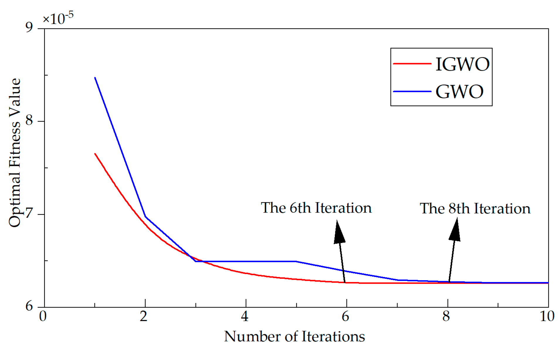
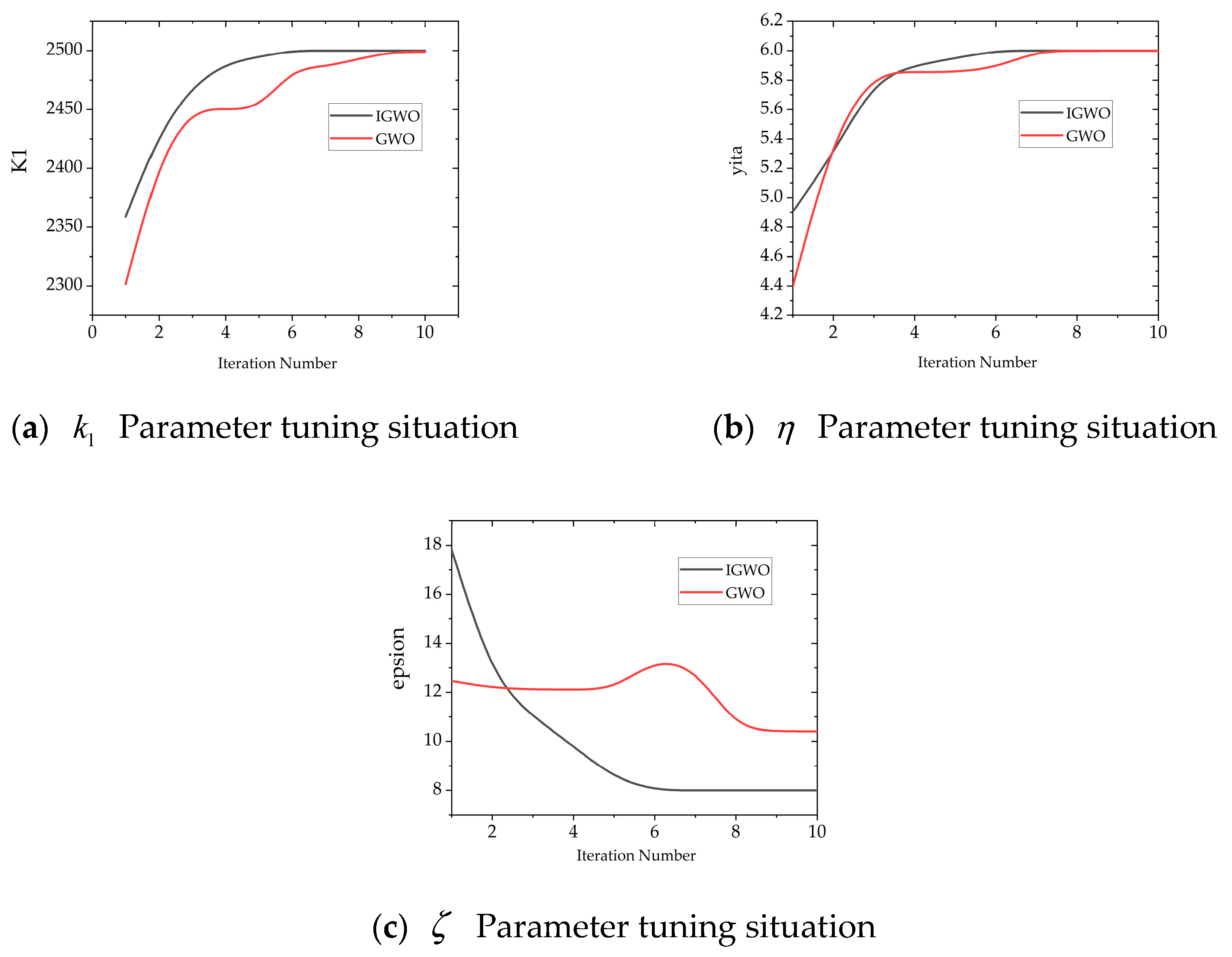
4.2. Improved Gray Wolf Optimization Fitness Function Analysis

The selection of the fitness function is generally flexible and can be tailored to the specific optimization objective. For short-time current loop optimization, the Integral of Absolute Error (IAE) is an effective criterion, as it enhances system response speed, improves current tracking performance, and reduces transient error [29]. Therefore, in current loop control, to achieve a stable current output, the cumulative error between the reference current and the actual output current is adopted as the fitness function. This function serves as an evaluation metric for the control performance of the system.
f i t n e s s = t = 0 t I ( t ) I ref
t denotes the total simulation time of the system; I represents the system output current; I ref indicates the reference (desired) current.
In the implementation of the Improved Gray Wolf Optimization algorithm, the population size is set to 100, the dimensionality of the solution space is 3, and the number of iterations is 10. The optimization performance comparison between the standard GWO and the Improved Gray Wolf Optimization (IGWO) is illustrated in Figure 7.
As shown in Figure 7, the GWO algorithm achieves its optimal fitness value at the 8th iteration, whereas the IGWO reaches its optimal solution as early as the 6th iteration, indicating a faster convergence rate. Moreover, the fitness curve of the improved algorithm is smoother with less fluctuation, demonstrating enhanced stability and robustness.
The variation in control parameter tuning during the optimization process is illustrated in Figure 8.

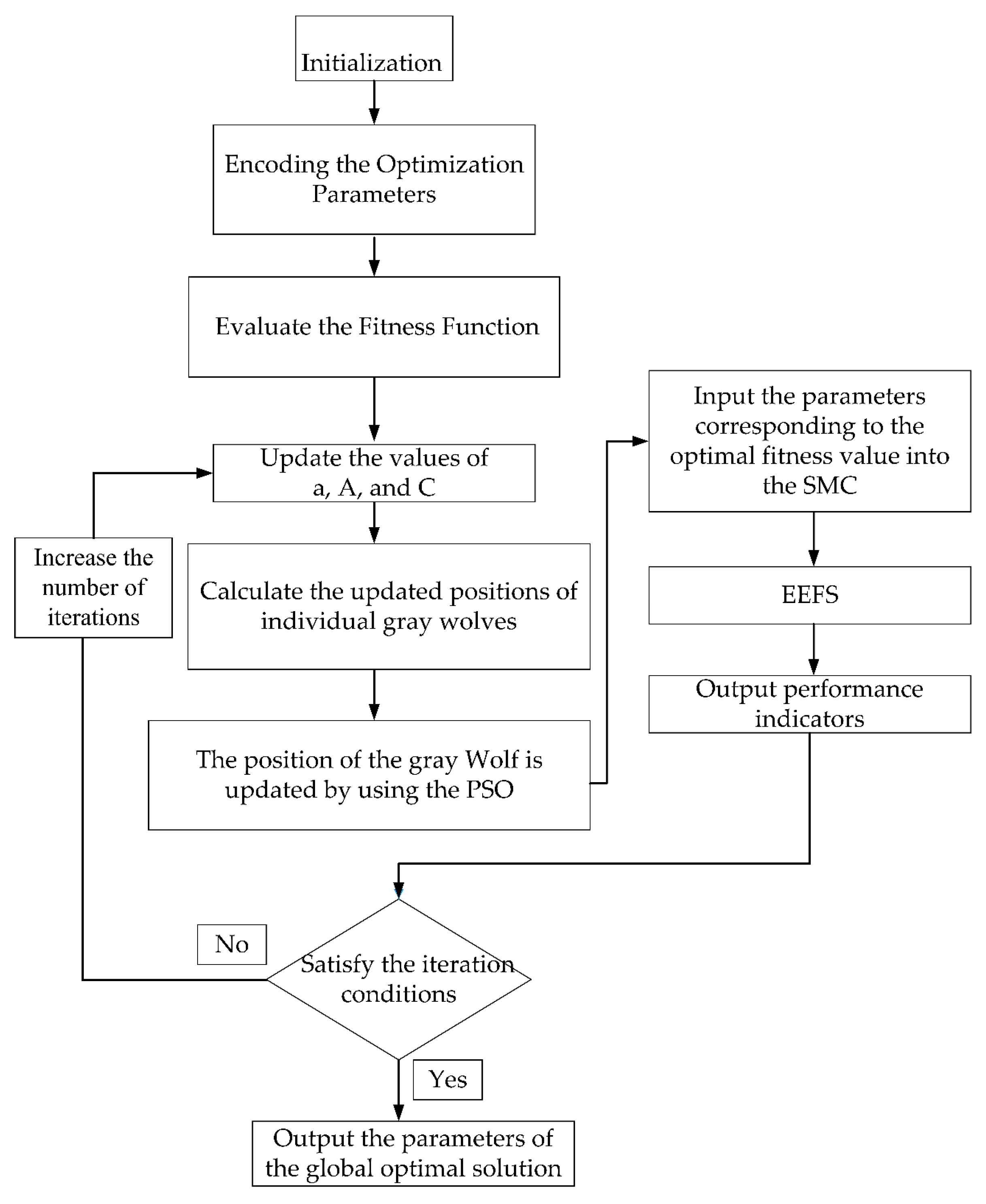
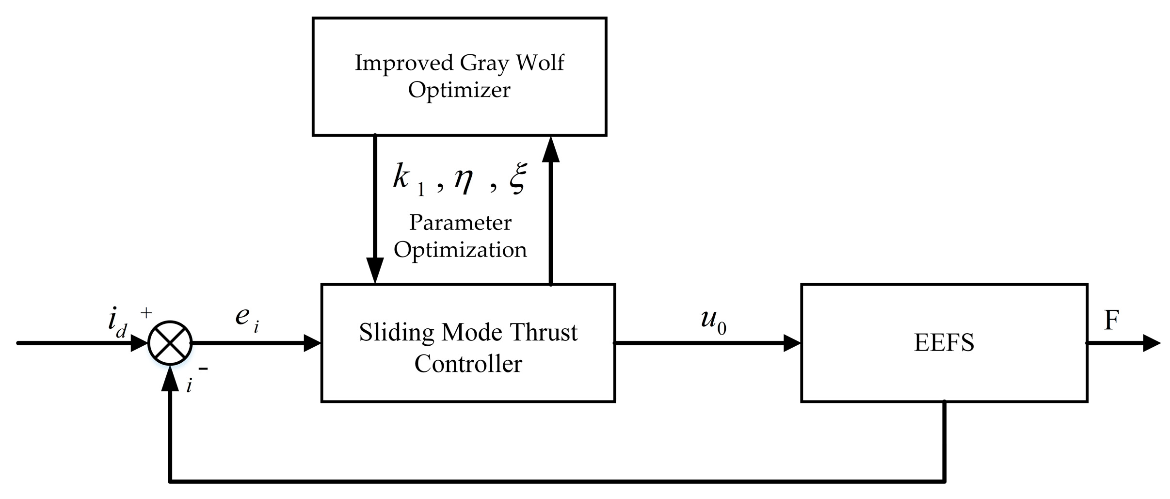
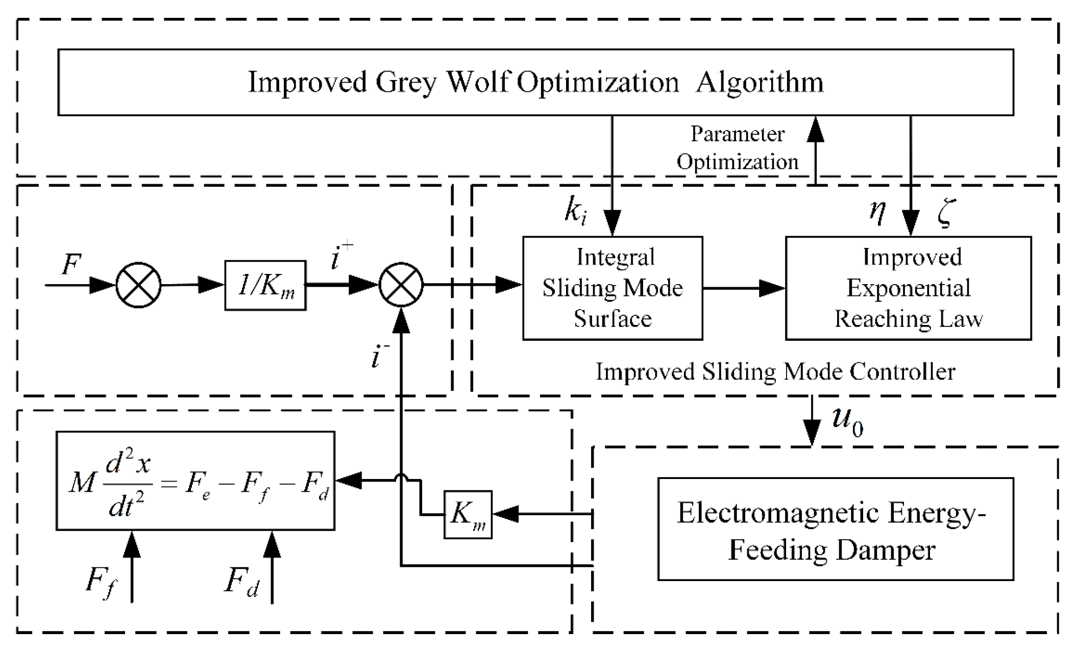
5. Design of a Sliding Mode Thrust Tracking Method Based on Improved Gray Wolf Optimization Algorithm

To ensure high tracking accuracy in the thrust control of the EEFS, this study addresses the limitations of conventional sliding surfaces by introducing a nonlinear integral sliding mode surface. This modification significantly improves the current response speed while effectively eliminating overshoot. Furthermore, a saturation function is adopted to replace the traditional sign function, thereby reducing the discontinuity in the control input. The smooth transition characteristics of the saturation function during the reaching phase help to suppress high-frequency chattering, ultimately enhancing both tracking accuracy and overall system stability.
To overcome the difficulty of manually tuning the parameters of the sliding mode controller, the IGWO algorithm is proposed. By incorporating the velocity update mechanism of the PSO, the global search capability of the GWO is effectively enhanced. Among the parameters of the sliding mode thrust controller, the three key parameters k 1 , η , ξ are difficult to optimize using empirical methods alone, while the remaining parameters can be determined through experience and set as constants.
In this section, the IGWO algorithm is integrated with the improved sliding mode controller to optimize the above-mentioned three parameters. The objective is to enhance control performance by automatically tuning k 1 , η , ξ to their optimal values.
The overall control framework is illustrated in Figure 9.

6. Simulation Analysis of Sliding Mode Thrust Controller Based on Improved Gray Wolf Optimization Algorithm

To verify the effectiveness of the GWO algorithm in sliding mode thrust control, this study takes an integrated EEFS as the research object. A simulation model of the thrust control system based on the IGWO-optimized sliding mode controller is established in Simulink for performance analysis.
The control parameters used in the simulation are listed in Table 1 and Table 2. And the system parameters are listed in Table 3.
Mization-based Sliding Mode Controller (IGWO-SMC) applied to the EEFS, a step input condition is selected.

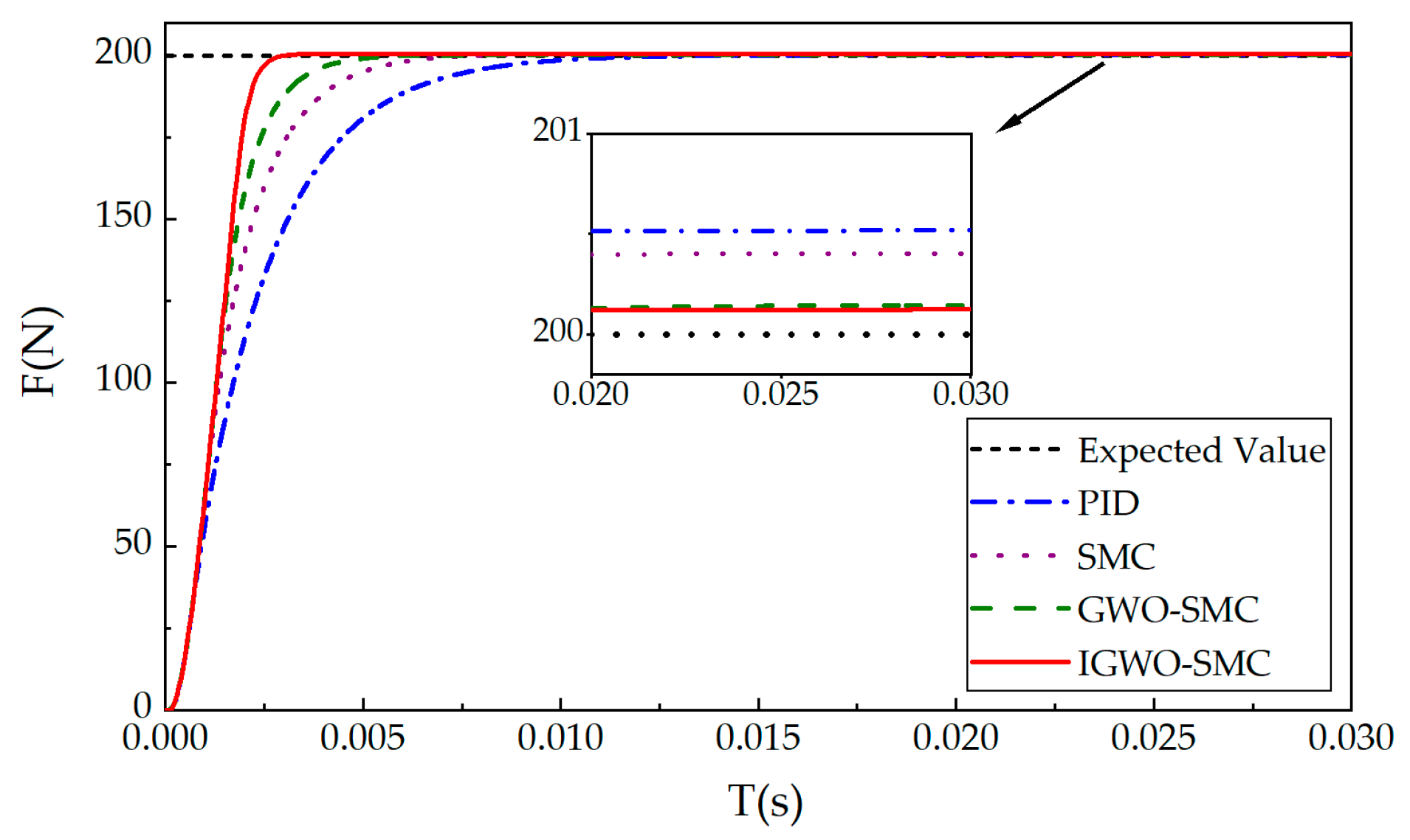
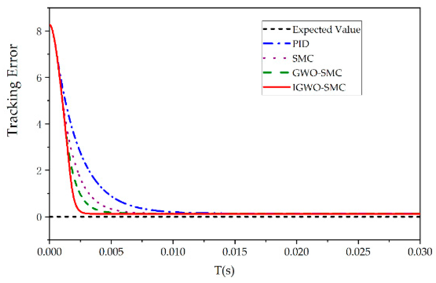
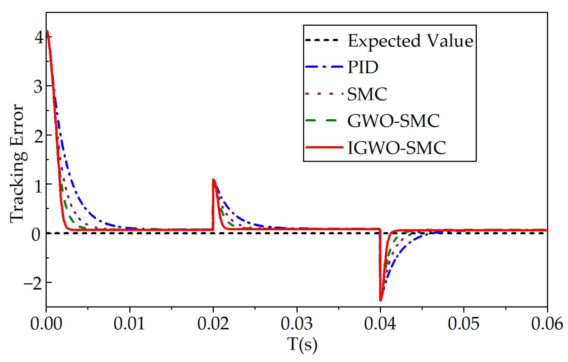
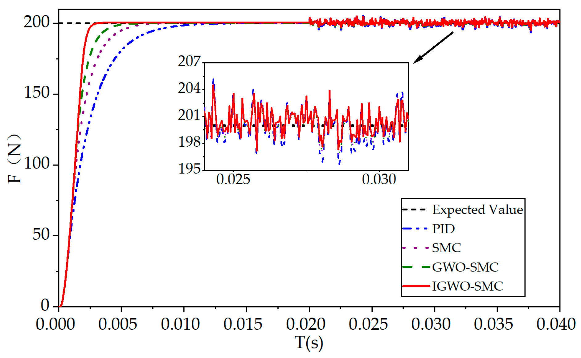
6.1. Step Response Condition Analysis

To evaluate the thrust tracking performance of the proposed Improved Gray Wolf Optimization-based Sliding Mode Controller (IGWO-SMC) applied to the EEFS, a step input condition is selected as the reference signal for simulation analysis.
Figure 10 illustrates the comparison of thrust tracking responses under step excitation for different control strategies, while Figure 10 presents the corresponding tracking error comparison. In this case, the target thrust is set to 200 N.
As shown in Figure 11, under the 200 N step input condition, the IGWO-SMC demonstrates significantly faster response speed and lower tracking error compared to other control methods. Whether during the transient response phase or in the steady-state phase, the IGWO-SMC exhibits superior control performance.
As shown in Table 4, the performance indicators under step input conditions demonstrate that the PID controller achieves a rise time of 0.0048 s, a settling time of 0.0081 s, and a steady-state error of 0.55 N. The conventional sliding mode controller (SMC) improves these metrics with a rise time of 0.0034 s, settling time of 0.0053 s, and a steady-state error of 0.4 N. The GWO-optimized sliding mode controller further enhances performance, achieving a rise time of 0.0026 s, settling time of 0.0039 s, and a reduced steady-state error of 0.15 N. The proposed Improved GWO-based SMC exhibits the best performance, with the shortest rise time of 0.002 s, the fastest settling time of 0.0025 s, and the lowest steady-state error of only 0.12 N. These results clearly indicate that the improved GWO-based sliding mode controller outperforms all other methods in step response performance. In particular, the significant reduction in steady-state error highlights its superior control precision when the system approaches the target value.
To further evaluate the controller’s adaptability to external disturbances or varying target references, a dynamic condition test was conducted. The system is set to have a target thrust of 200 from 0 to 0.02 s, a change of 250 from 0.02 to 0.04 s, and a decrease of 180 from 0.04 to 0.06 s. The comparison of system responses under these dynamic conditions, as well as the corresponding tracking errors for different controllers, are shown in Figure 12 and Figure 13, respectively.
As illustrated in Figure 12 and Figure 13, the IGWO-SMC demonstrates superior responsiveness and stability following target variations, outperforming the other controllers under dynamic operating conditions.
The PID controller exhibits a relatively slow response, with a prolonged transition period and poor stability, making it difficult for the system to quickly adjust to new reference values. Although the SMC shows certain improvements over the PID controller, its response speed and overall stability remain insufficient.
Compared to the conventional SMC, the GWO-optimized SMC achieves faster adjustment to new targets and exhibits better stability. However, the IGWO-SMC offers the best dynamic performance, responding rapidly and smoothly to changes in the reference thrust. It effectively suppresses overshoot during the transition process, demonstrating excellent adaptability and robust control capability under varying operating conditions.

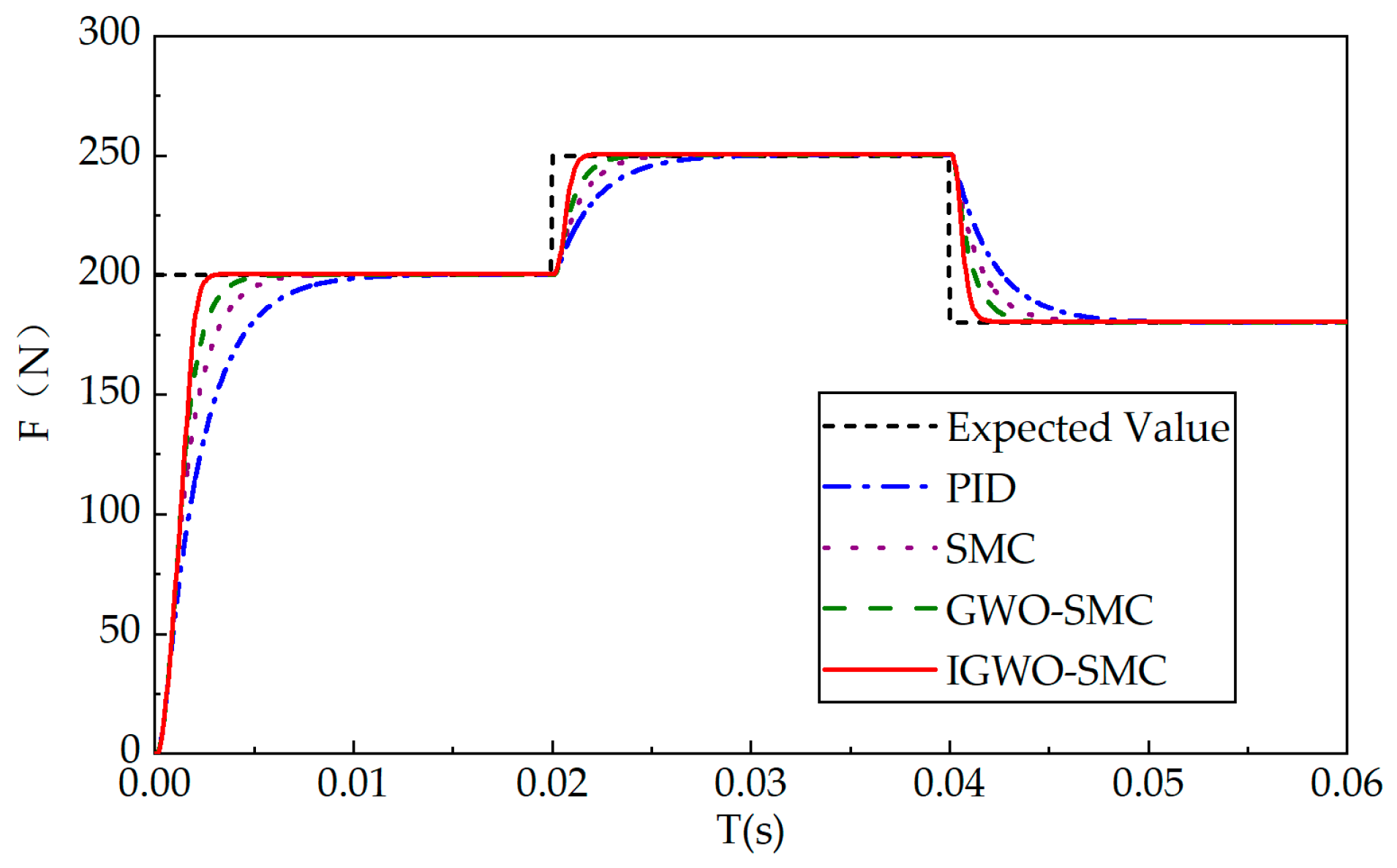
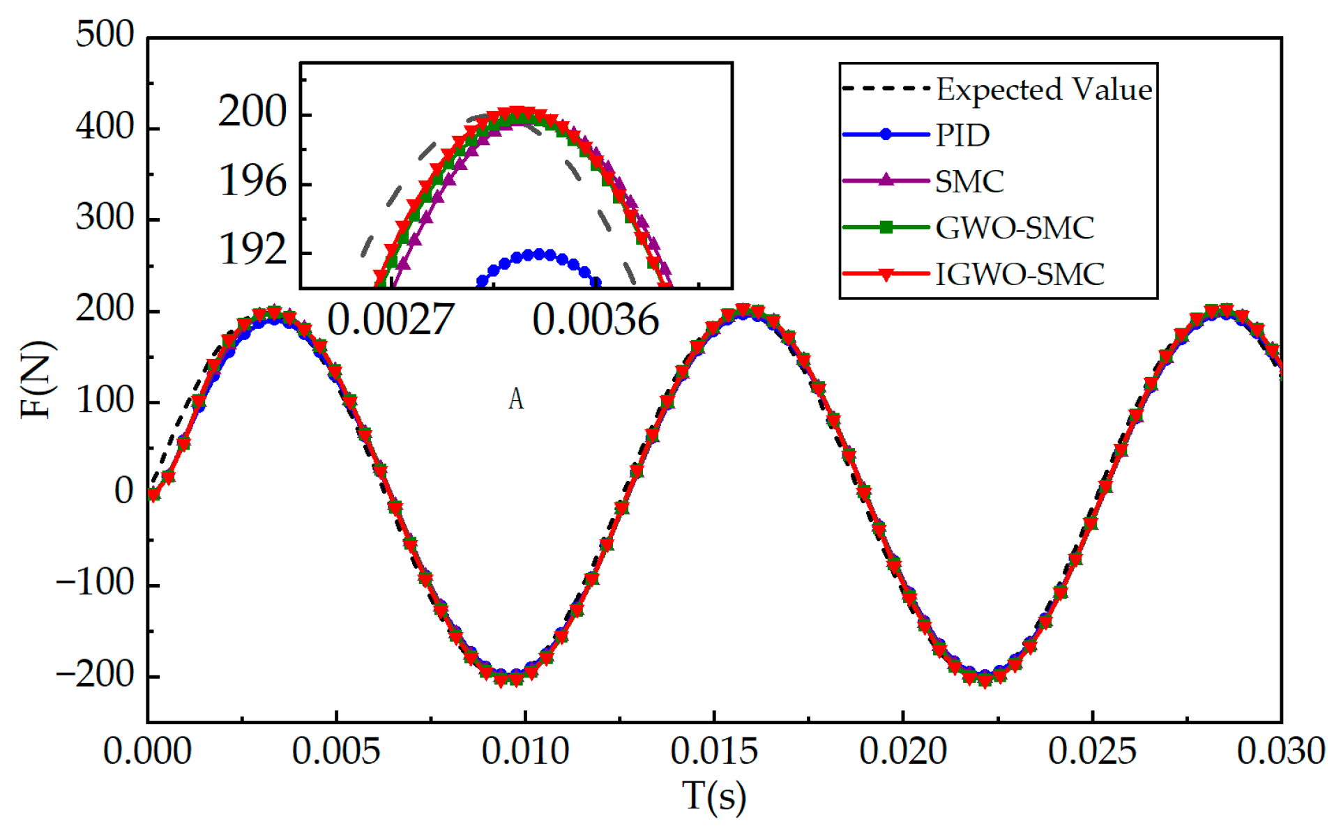
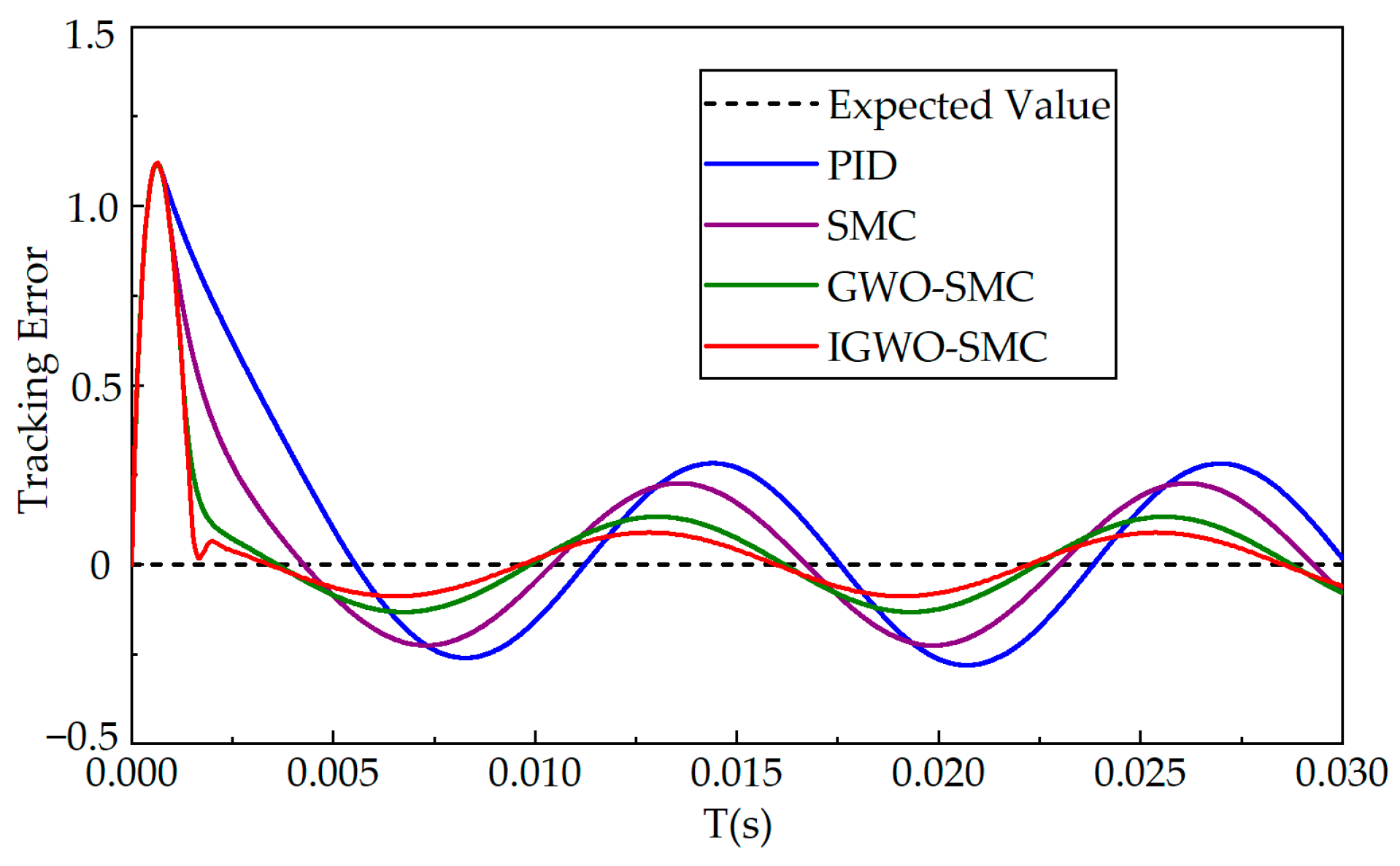
6.2. Sinusoidal Condition Analysis

To evaluate the thrust tracking performance of the IGWO-SMC under sinusoidal operating conditions, a reference input with a frequency of 500 rad/s and an amplitude of 500 N was applied. The thrust tracking results of different controllers under this periodic input are illustrated in Figure 14, and the corresponding tracking error comparisons are shown in Figure 15.
As observed from the figures, all four controllers are capable of tracking the target sinusoidal curve under the given conditions. However, the IGWO-SMC exhibits significantly better control performance. It achieves faster response in both the gradual rising segments and the peak regions of the sinusoidal waveform. Furthermore, the tracking accuracy of the improved controller consistently surpasses that of the other control strategies throughout the entire cycle, demonstrating its superior precision and dynamic response capability in periodic tracking tasks.
As shown in Table 5, the PID controller exhibits a maximum error of 1.23 N and an average error of 0.28 N under sinusoidal conditions. The conventional sliding mode controller achieves a slightly better performance, with a maximum error of 1.22 N and an average error of 0.26 N. The GWO-optimized sliding mode controller further improves the results, reducing the maximum error to 1.20 N and the average error to 0.17 N, reflecting its enhanced tracking accuracy. The IGWO-SMC demonstrates the best performance, with the lowest maximum error of 1.19 N and an average error of only 0.12 N, effectively tracking the sinusoidal reference and exhibiting minimal steady-state error.

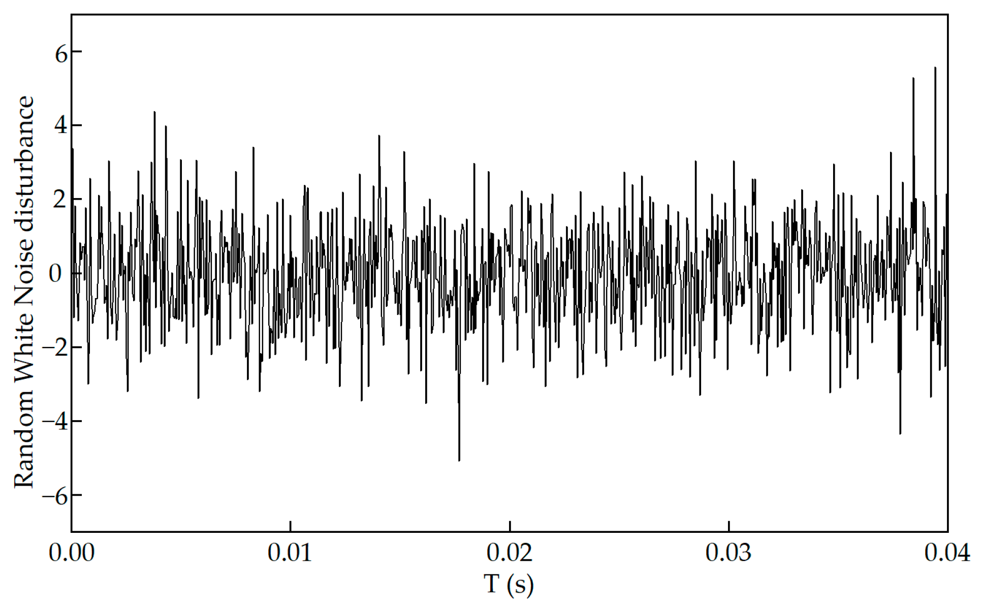
6.3. Noise Disturbance Analysis

Noise disturbances can compromise system stability and output accuracy. Considering that EEFS often operate in harsh environments, it is essential to evaluate the control system’s robustness under noisy conditions.
To assess this, a random white noise disturbance with a power of 0.0001 and a variance of 2 was introduced at 0.02 s during the step response test. The profile of the injected noise is illustrated in Figure 16, and the corresponding control responses of different controllers under this noisy condition are compared in Figure 17.
The simulation results reveal that the IGWO-SMC maintains superior stability and noise rejection capability, ensuring accurate thrust tracking even in the presence of significant external disturbances.
As illustrated in Figure 17 under the influence of noise disturbances, the thrust tracking accuracy of all controllers is affected to varying degrees. However, IGWO-SMC maintains relatively low chattering despite continuous disturbance. Compared with other control strategies, it demonstrates superior thrust tracking accuracy and enhanced robustness, effectively mitigating the impact of noise on system performance.
Table 6 shows a comparison of performance data of different controllers under noise disturbance.
According to Table 6, the robustness of each controller under noise disturbance varies significantly:
The PID controller exhibits the weakest robustness, with a maximum deviation of 7.73 N and an average deviation of 3.18 N, indicating poor disturbance rejection.
The conventional sliding mode controller shows improved performance, reducing the maximum deviation to 6.51 N and the average deviation to 2.77 N, though notable errors remain.
The GWO-based sliding mode controller further enhances noise immunity, achieving a maximum deviation of 5.32 N and an average deviation of 2.31 N.
The IGWO-SMC delivers the best performance, with a maximum deviation of 4.85 N and an average deviation of 2.14 N, demonstrating superior capability in suppressing external disturbances while maintaining low tracking errors.
These results confirm that the proposed IGWO-SMC offers enhanced robustness and precision in noisy environments, making it well-suited for high-performance thrust tracking applications in Electromagnetic Energy-Feeding Shock Absorber systems.

7. Conclusions

This paper addresses the issues of low thrust tracking accuracy, slow dynamic response, and difficulty in parameter tuning commonly encountered in conventional sliding mode control strategies for Electromagnetic Energy-Feeding Shock Absorber systems. A novel sliding mode control method based on the IGWO algorithm is proposed.
By integrating a velocity update mechanism inspired by PSO, the global search capability of the standard GWO algorithm is significantly enhanced. Moreover, the proposed control strategy incorporates a nonlinear integral sliding surface and an adaptive reaching law, which effectively mitigates the chattering typically observed in sliding mode control, thereby improving thrust tracking accuracy and enhancing overall system dynamic performance.
Simulation results validate the effectiveness of the proposed method. The IGWO-SMC demonstrates excellent tracking precision and fast response under both step and sinusoidal operating conditions. Additionally, it exhibits strong adaptability in time-varying conditions, allowing the system to swiftly and stably adjust to new reference values. Even under random white noise disturbances, the controller maintains robust tracking performance, highlighting its superior noise resistance and robustness, making it a highly promising approach for advanced thrust control in electromagnetic linear actuators.

Author Contributions

Methodology, W.Z.; Software, W.Z. and C.T.; Data curation, X.X. and H.Z.; Writing—original draft, W.Z.; Writing—review and editing, J.L. and. W.G. All authors have read and agreed to the published version of the manuscript.

Funding

This research was funded by Shandong Association for Science\& Technology (Grant No.: SDAST2024QTA061), the National Natural Science Foundation of China (Grant No.: 52305265), the Postdoctoral Science Foundation of China (Grant No.: 2023M732113), the Major Scientific and Technological Innovation Project of Shandong Province Key Research and Development Program (Grant No. 2023CXGC010211).

Data Availability Statement

The raw data supporting the conclusions of this article will be made available by the authors on request.

Conflicts of Interest

The authors declare no conflicts of interest.

References

  1. Ibrahim, B.; Abdelkader, H.; Hartani, M.A.; Kayisli, K. Optimization of Sliding Mode Control for Doubly Fed Induction Generator Systems Using Particle Swarm and Grey Wolf Algorithms. Electr. Power Compon. Syst. 2024, 52, 1782–1795. [Google Scholar] [CrossRef]
  2. Lu, J.; Li, B.; Ge, W.; Tan, C.; Sun, B. Analysis and experimental study on servo dynamic stiffness of electromagnetic linear actuator. Mech. Syst. Signal Process. 2022, 169, 108587. [Google Scholar] [CrossRef]
  3. Wei, C.; Jing, X. A comprehensive review on vibration energy harvesting: Modelling and realization. Renew. Sustain. Energy Rev. 2017, 74, 1–18. [Google Scholar] [CrossRef]
  4. Baskys, A. A Combined Controller for Closed-Loop Control Systems Affected by Electromagnetic Interference. Sensors 2024, 24, 1466. [Google Scholar] [CrossRef]
  5. Liangxu, X.; Xiaodong, Y. Research on PMSM Control Based on ADRC, Shanghai Dianji Unversity (China); Mingo New Motor Electric Control Research Institute (China): Beijing, China, 2022. [Google Scholar]
  6. Pérez-San Lázaro, R.; Mendoza-Bautista, K.J.; Fuentes-Aguilar, R.Q.; Chairez, I. State-restricted adaptive control of a multilevel rotating electromagnetic mechanical flexible device using electromagnetic actuators. ISA Trans. 2024, 155, 346–360. [Google Scholar] [CrossRef]
  7. Wang, S.; Zhao, W.; Zong, X.; Zhang, W. Optimal Control Model of Electromagnetic Interference and Filter Design in Motor Drive System. Electronics 2025, 14, 980. [Google Scholar] [CrossRef]
  8. Khater, A.A.; Fekry, M.; El-Bardini, M.; El-Nagar, A.M. Deep reinforcement learning-based adaptive fuzzy control for electro-hydraulic servo system. Neural Comput. Appl. 2025, 1–18. [Google Scholar] [CrossRef]
  9. Cui, B.; Chen, Y.; Hong, X.; Luo, H.; Chen, G. Research on Path-Following Technology of a Single-Outboard-Motor Unmanned Surface Vehicle Based on Deep Reinforcement Learning and Model Predictive Control Algorithm. J. Mar. Sci. Eng. 2024, 12, 2321. [Google Scholar] [CrossRef]
  10. Shao, K. A finite-time speed control method for permanent magnet synchronous motor drives based on sliding mode control and estimation theory. Electr. Eng. 2025, 1–12. [Google Scholar] [CrossRef]
  11. Sun, H.; Gao, L.; Zhao, Z.; Li, B. Adaptive super-twisting fast nonsingular terminal sliding mode control with ESO for high-pressure electro-pneumatic servo valve. Control. Eng. Pract. 2023, 134, 105483. [Google Scholar] [CrossRef]
  12. Zhao, Y.; Lin, H.; Li, B. Sliding-Mode Clamping Force Control of Electromechanical Brake System Based on Enhanced Reaching Law. IEEE Access 2021, 9, 19506–19515. [Google Scholar] [CrossRef]
  13. Ruan, W.; Dong, Q.; Zhang, X.; Li, Z. Friction compensation control of electromechanical actuator based on neural network adaptive sliding mode. Sensors 2021, 21, 1508. [Google Scholar] [CrossRef]
  14. Mehra, V.; Shah, D. Parameter optimization of reaching law based sliding mode control by computational intelligence techniques. In International Conference on Soft Computing and its Engineering Applications; Springer: Singapore, 2020; pp. 88–100. [Google Scholar]
  15. Ayinalem, A.Z.; Kassie, T.A. PSO Tuned Super-Twisting Sliding Mode Controller for Trajectory Tracking Control of an Articulated Robot. J. Electr. Comput. Eng. 2025, 2025, 1171569. [Google Scholar] [CrossRef]
  16. Xiong, X.; Pan, Z.; Yang, G.; Chen, C.; Xu, F.; Zhu, B. An adaptive robust sliding mode control strategy based on radial basis function neural networks for the magnetorheological semi-active suspension. Proc. Inst. Mech. Eng. 2025, 239, 1131–1142. [Google Scholar] [CrossRef]
  17. Liu, L.; Wang, X.; Xie, J.; Wang, X.; Liu, H.; Li, J.; Wang, P.; Yang, X. Path planning and tracking control of orchard wheel mower based on BL-ACO and GO-SMC. Comput. Electron. Agric. 2025, 228, 109696. [Google Scholar] [CrossRef]
  18. Gad, O.M.; Fareh, R.; Tawfik, H.; Sinan, S.; Khadraoui, S.; Bettayeb, M. Optimized Power Rate Sliding Mode Control for a Robot Manipulator Using Genetic Algorithms. Int. J. Control Autom. Syst. 2024, 22, 3166–3176. [Google Scholar] [CrossRef]
  19. Soreng, B.; Pradhan, R. Optimal controller design for an islanded microgrid during load change. Int. J. Grid Util. Comput. 2021, 12, 237–252. [Google Scholar] [CrossRef]
  20. Park, G.; Choi, S.B. Clamping force control based on dynamic model estimation for electromechanical brakes. Proc. Inst. Mech. Eng. Part D J. Automob. Eng. 2018, 232, 2000–2013. [Google Scholar] [CrossRef]
  21. Lu, Y.; Lu, J.; Tan, C.; Tian, M.; Dong, G. Adaptive Non-Singular Terminal Sliding Mode Control Method for Electromagnetic Linear Actuator. Micromachines 2022, 13, 1294. [Google Scholar] [CrossRef]
  22. González-Prieto, J.A. Adaptive finite time smooth nonlinear sliding mode tracking control for surface vessels with uncertainties and disturbances. Ocean. Eng. 2023, 279, 114474. [Google Scholar] [CrossRef]
  23. Ma, D.; Lin, H.; Li, B. Chattering-Free Sliding-Mode Control for Electromechanical Actuator with Backlash Nonlinearity. J. Electr. Comput. Eng. 2017, 2017, 6150750. [Google Scholar] [CrossRef]
  24. Mirjalili, S.; Mirjalili, S.M.; Lewis, A. Grey Wolf Optimizer. Adv. Eng. Softw. 2014, 69, 46–61. [Google Scholar] [CrossRef]
  25. Madadi, A.; Motlagh, M.M. Optimal control of DC motor using grey wolf optimizer algorithm. Tech. J. Eng. Appl. Sci. 2014, 4, 373–379. [Google Scholar]
  26. Zhang, J.; Yang, F.; Nie, G.; Li, Y. Optimal Trajectory Planning for Minimizing Base Disturbance of a Redundant Space Robot with IQPSO. J. Electr. Comput. Eng. 2022, 2022, 3398810. [Google Scholar] [CrossRef]
  27. Dhiman, G.; Kumar, V. Spotted hyena optimizer: A novel bio-inspired based metaheuristic technique for engineering applications. Adv. Eng. Softw. 2017, 114, 48–70. [Google Scholar] [CrossRef]
  28. Zhang, X.; Lin, Q.; Mao, W.; Liu, S.; Dou, Z.; Liu, G. Hybrid Particle Swarm and Grey Wolf Optimizer and its application to clustering optimization. Appl. Soft Comput. 2021, 101, 107061. [Google Scholar] [CrossRef]
  29. Fessi, R.; Rezk, H.; Bouallègue, S. Grey wolf optimization based tuning of terminal sliding mode controllers for a quadrotor. Comput. Mater. Contin. 2021, 68, 2265–2282. [Google Scholar] [CrossRef]
Figure 1. Structure schematic diagram of moving coil type electromagnetic linear actuator.
Wevj 16 00366 g001
Figure 2. Sliding mode thrust tracking control block diagram.
Wevj 16 00366 g002
Figure 3. Comparison of Symbolic and Saturation Functions.
Wevj 16 00366 g003
Figure 4. Schematic diagram of hunting and searching prey of gray wolf population.
Wevj 16 00366 g004
Figure 5. Improve the flowchart of the Gray Wolf optimization algorithm.
Wevj 16 00366 g005
Figure 6. Improved Gray Wolf Optimization Algorithm Control Structure Diagram.
Wevj 16 00366 g006
Figure 7. Optimal Fitness Value Comparison Curve Between Gray Wolf Optimization and Improved Gray Wolf Optimization.
Wevj 16 00366 g007
Figure 8. Parameter Tuning Variation Diagram.
Wevj 16 00366 g008
Figure 9. Improved gray wolf algorithm sliding mode control system block diagram.
Wevj 16 00366 g009
Figure 10. Comparison of thrust tracking performance of different controllers under step input conditions.
Wevj 16 00366 g010
Figure 11. Comparison of thrust tracking errors of different controllers under step operating conditions.
Wevj 16 00366 g011
Figure 12. Comparison of system operating condition change response (target 200–250–180 change) figure.
Wevj 16 00366 g012
Figure 13. Error comparison diagram of working condition variation.
Wevj 16 00366 g013
Figure 14. Comparison of thrust tracking of different controllers under sinusoidal conditions.
Wevj 16 00366 g014
Figure 15. Thrust tracking of different controllers under sinusoidal conditions. Error comparison diagram of different controllers under sinusoidal conditions.
Wevj 16 00366 g015
Figure 16. Random white noise diagram.
Wevj 16 00366 g016
Figure 17. Comparison of response of different controllers under noise disturbance.
Wevj 16 00366 g017
Table 1. Table of PID Controller Parameters.
Controller k p k i k d
PID5.22.10.05
Table 2. Control Parameters Table for Different Controllers.
Controller k 1 η ξ
SMC2.56.08.5
GWO-SMC2.3794535.9795158.241134
IGWO-SMC2.49501695.996910838.618871
Table 3. Table of System Parameters.
System Parameters M L R
Numerical Values2.885 Kg7.765 mH6.4 Ω
Table 4. Comparison of the performance data of different controllers under different thrust tracking errors under step conditions.
ControllerRise Time/sSettling Time/s
PID0.00480.0081
SMC0.00340.0053
GWO-SMC0.00260.0039
IGWO-SMC0.0020.0025
Table 5. Comparison of performance data of different controllers under sinusoidal conditions.
ControllerMaximum Error/NAverage Error/N
PID1.230.28
SMC1.220.26
GWO-SMC1.200.17
IGWO-SMC1.190.12
Table 6. Comparison of performance data of different controllers under noise disturbance.
ControllerMaximum Error /NAverage Error/N
PID7.733.18
SMC6.512.77
GWO-SMC5.322.31
IGWO-SMC4.852.14
Disclaimer/Publisher’s Note: The statements, opinions and data contained in all publications are solely those of the individual author(s) and contributor(s) and not of MDPI and/or the editor(s). MDPI and/or the editor(s) disclaim responsibility for any injury to people or property resulting from any ideas, methods, instructions or products referred to in the content.

