1. Introduction
Brushless DC (BLDC) motors are highly valued for their compact design, superior power efficiency, and durable structure, making them ideal for various industrial and household applications [
1,
2]. Compared to traditional brushed DC motors, BLDC motors do not require mechanical commutators or brushes, resulting in increased reliability and reduced mechanical noise [
3]. In electric vehicles (EVs), BLDC hub motors consist of a rotor with permanent magnets, a stator with electromagnets, Hall sensors, and a shaft. Their brushless, contactless design allows for smooth, efficient, and quiet operation. As the demand for EVs continues to rise due to environmental and economic factors, BLDC hub motors have come to dominate the market (80–85%) because of their high efficiency, excellent torque-to-mass ratio, low cost, and minimal noise production [
4]. Despite their benefits, challenges such as electromagnetic interference, torque ripple, and acoustic noise can still limit their performance. This study seeks to tackle these issues by focusing on reducing torque ripple and enhancing efficiency.
One of the primary limitations of nonsinusoidal BLDC motors is commutation torque ripple, which causes vibration and noise, thereby restricting their use in precision applications such as servo and robotic systems [
5]. As a result, much of the recent research has concentrated on methods to reduce commutation torque ripple [
6]. The approaches to mitigating torque ripple can generally be categorized into two main areas: motor design modifications and advancements in control algorithms.
Motor design improvements include methods like short-pitch and fractional-slot windings, optimizing stator slot openings, skewing, and fine-tuning rotor magnet configurations [
7]. While these approaches can help reduce torque ripple and improve efficiency, they tend to increase production complexity and costs. On the other hand, advancements in control algorithms, such as designing current and torque control loops, offer more cost-effective solutions [
8,
9].
Torque ripple in BLDC motors has been extensively analyzed due to its negative impact on motor performance and efficiency. Initial analytical studies [
10] indicate that the magnitude of commutation torque ripple depends more on the relationship between back electromotive force (EMF) and DC-link voltage rather than on the amplitude of the phase current. Traditional two-phase conduction methods produce quasi-square current waveforms, which cause abrupt transitions during commutation, resulting in noticeable torque ripple. This problem worsens at higher speeds as the winding inductance causes delays in the phase current, further reducing motor efficiency [
11,
12].
To address torque ripple, a variety of hardware and control solutions have been developed. Integrating DC–DC converters with three-phase inverters can improve voltage control and reduce torque ripple, as shown in [
13,
14,
15], but these approaches add complexity and increase system costs. Similarly, PWM techniques like the 120-degree commutation method [
16,
17,
18,
19] have been employed to reduce ripple; however, these require non-complementary switching of voltage source inverter (VSI) transistors, which decreases the effective utilization of the DC voltage and poses implementation challenges.
More contemporary solutions focus on refined current control to minimize torque oscillations. Techniques such as predictive phase current control during commutation [
20] and current vector optimization through phase-advancing strategies [
21] help minimize torque ripple across a broad speed range. Additional methods including average torque control [
22], spider-based regulation, and integral variable structure control [
23] enhance dynamic stability and response. Particularly, hysteresis-based direct DC-link current control (DDLCC) stands out by offering a simpler, sensorless approach that reduces torque ripple without relying on complex torque control or additional current sensors, striking a practical balance between control performance and system simplicity.
This study proposes a novel approach to minimize current harmonics in BLDC motors through the introduction of the Sigmoid Trapezoidal Current Model. This model improves the current waveform during commutation by incorporating a smooth sigmoid function, thereby reducing sharp transitions and significantly lowering harmonic distortion. By replacing abrupt current changes with gradual ones, the method enhances motor performance, particularly in reducing speed and torque ripple, which is most prominent at low speeds. The proposed method integrates hysteresis PWM control to ensure precise current regulation within a specified hysteresis band. Furthermore, maintaining a consistent non-commutation phase current reduces harmonic distortion, leading to better motor stability and efficiency.
This research focuses on developing and implementing the Sigmoid Trapezoidal Current Model for BLDC motors and comparing its output current with the conventional BLDC motor current under hysteresis PWM control. The model’s performance in reducing current harmonics is compared with existing methods, and the solution is validated using MATLAB/Simulink simulations. The proposed approach demonstrates significant potential in improving motor efficiency and stability, making it ideal for applications in electric vehicles, drones, and robotics.
3. Three-Phase Voltage Equations
The three-phase stator winding of a BLDC motor is symmetrical, meaning the windings have equal resistance, inductance, and back electromotive force (EMF). The phase voltage equations for this system are given as:
where
,
are the phase voltages,
,
,
are the corresponding phase currents, and
,
,
are the back EMFs of the phases.
represents the neutral voltage, while
and
denote the resistance and inductance per phase, respectively.
The instantaneous electromagnetic torque produced by the BLDC motor can be calculated as:
Here,
is the motor’s angular speed in radians per second.
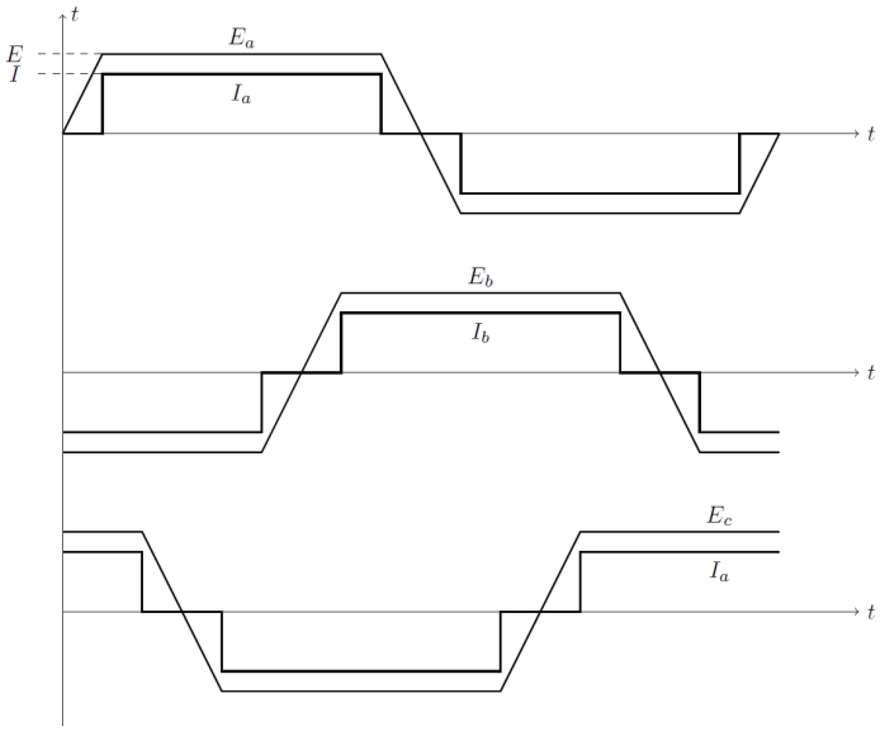
Figure 2 illustrates the ideal trapezoidal back EMF and phase current waveforms of a BLDC motor, as described in [
23], which exhibit a trapezoidal shape for optimized torque production.
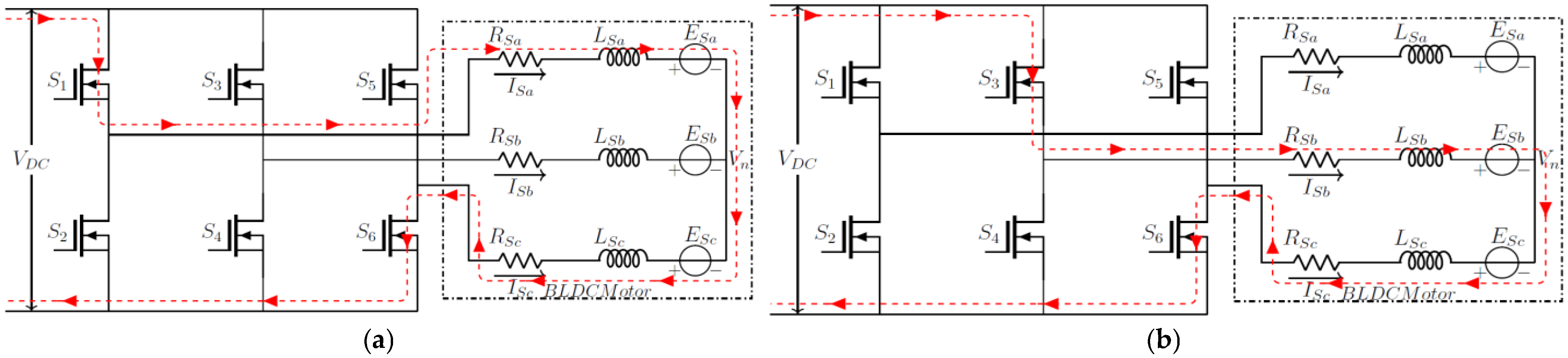
3.1. Operational Modes: Non-Commutation and Commutation
During the motor’s non-commutation period, only two phases conduct at any given moment, as shown in
Figure 3a. For instance, if the current flows through Phases A and C, then Phase Bremains inactive. When transitioning to the commutation period, the current alternates between phases, as depicted in
Figure 3b. For example, when Phase A is turned off and Phase Bis activated, the current shifts, while Phase Ccontinues to conduct.
3.2. Voltage Equations During Commutation
The voltage equations for the commutation interval are given by:
For a star-connected winding, the neutral voltage
is calculated as:
3.3. Phase Current Dynamics
The rate of change of phase currents during commutation is derived from the above equations as follows:
Here,
is the commutation time.
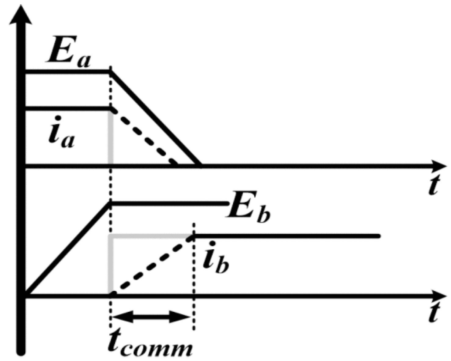
Figure 4 shows thetransition of phase current from Phase A to Phase B.
The rise (
) and fall (
) times of phase currents can be expressed as:
3.4. Torque Ripple During Commutation
Torque ripple during commutation can be calculated as:
Assuming
, the torque ripple becomes:
To minimize torque ripple, the second term in Equation (13) must approach zero. This condition is satisfied when the rise time () of the incoming phase current equals the fall time () of the outgoing phase current. For simplicity, the resistive drop is often ignored during analysis. Balancing these times ensures reduced operational vibration and reduced torque oscillations.
3.5. Sigmoid Trapezoidal Current Equation for BLDC Motor
The Sigmoid Trapezoidal Current equation for a BLDC motor is designed to create a current profile that combines the gradual characteristics of a sigmoid function with the traditional trapezoidal waveform used for commutation. This design is especially effective in minimizing torque ripple during motor operation, particularly during commutation. The current profile takes on a trapezoidal shape, where the current gradually increases to a peak value, remains constant at this peak (the flat top of the trapezoid), and then decreases symmetrically. The sigmoid function provides a seamless transition between the zero, rising, flat, and falling phases of the trapezoidal waveform, ensuring a gradual change in current. This eliminates sudden current changes that could lead to torque ripple, enhancing the motor’s performance and efficiency.
The sigmoid function is a useful mathematical tool for creating soft current transitions between different stages of a current waveform, particularly when generating a trapezoidal current profile. It helps model the transitions from zero current, through the rising phase, and into the falling phase of the waveform. The general form of the sigmoid function is:
In this equation, S(t) represents the value of the sigmoid function at time t, k is the steepness factor that controls the sharpness of the transition, and is the midpoint where the transition occurs. This function ensures that the current progresses steadily between different segments of the waveform.
The current profile i(t) consists of three key segments:
Rising Segment: This is where the current increases from zero to the maximum value .
Flat Segment: During this phase, the current remains constant at the maximum value .
Falling Segment: Here, the current decreases from the maximum value back down to zero.
The durations of these segments are represented by the following:
, the duration of the rising phase;
, the duration when the current stays constant;
the duration of the falling phase.
By defining these segments, we can describe the full current equation for the BLDC motor. The sigmoid function controls the transitions during the rising and falling segments, while the flat segment ensures the current remains constant at . This results in a low-noise, trapezoidal current profile that avoids sudden changes, improving motor control and reducing current ripple.
The Sigmoid Trapezoidal Current Profile is utilized in three-phase BLDC motors to achieve reducedcurrent discontinuities and balanced operation across all phases. This method ensures that the current in each phase is 120 degrees out of phase with the others, which is critical for balanced torque generation and efficient motor performance. The transitions provided by the sigmoid function help reduce torque ripple and avoid abrupt changes in current that could cause inefficiencies. In a three-phase BLDC motor, the current waveforms are designed to be phase-shifted relative to each other by 120 degrees. This phase shift ensures balanced operation and low noise commutation. Each phase current follows a trapezoidal profile with three segments: rising, flat, and falling.
3.6. Current Equation for Phase A
The current waveform for Phase A is defined as a piecewise function comprising three segments: a rising segment, a flat segment, and a falling segment. In the rising segment, the current increases from zero to its maximum value,
, using a sigmoid function to ensure a gradual transition. This gradual rise prevents sudden spikes in current, which could otherwise lead to undesirable torque ripple. During the flat segment, the current remains constant at
, providing a steady and uniform output. Finally, in the falling segment, the current decreases from
back to zero, once again governed by the sigmoid function to avoid abrupt changes.
where
is the midpoint of the sigmoid transition. The transition between these segments is influenced by the parameter
k, which determines the steepness of the sigmoid curve. By controlling the rate of transition, k ensures a gradual shift between the segments, leading to reduced harmonic distortion and improve motor performance.
- 1.
Phase B and Phase C Current Equations
The current waveforms for Phase B and Phase C follow a similar pattern to that of Phase A but are phase-shifted by 120 degrees and 240 degrees, respectively. These phase shifts are critical for maintaining the balance in a three-phase system. The current in Phase B is delayed by , and the current in Phase C is delayed by , where T represents the period of a complete cycle.
Although the structure of the reference current equations for Phases B and C mirrors that of Phase A, each phase’s waveform is time-shifted by 120° and 240°, respectively. These phase shifts introduce deliberate overlaps in the conduction intervals of adjacent phases. Such overlapping of incoming and outgoing phase currents during commutation is essential in BLDC motors, as it enables continuous electromagnetic torque generation. This staggered distribution helps balance the load on the motor, promoting low rippletorque production. The rising, flat, and falling segments in these phases are similarly controlled by the sigmoid function, ensuring soft transitions. The balanced currents across all three phases significantly reduce harmonic distortion and contribute to consistent and efficient torque generation.
The application of the sigmoid trapezoidal current profile across all phases minimizes high-frequency harmonics that can lead to motor noise, vibrations, and inefficiencies. The gradual transitions between the rising, flat, and falling segments reduce abrupt current changes, enhancing overall motor performance. This approach also decreases mechanical wear on motor components, improving reliability and longevity.
- 2.
BLDC Motor Control Loop
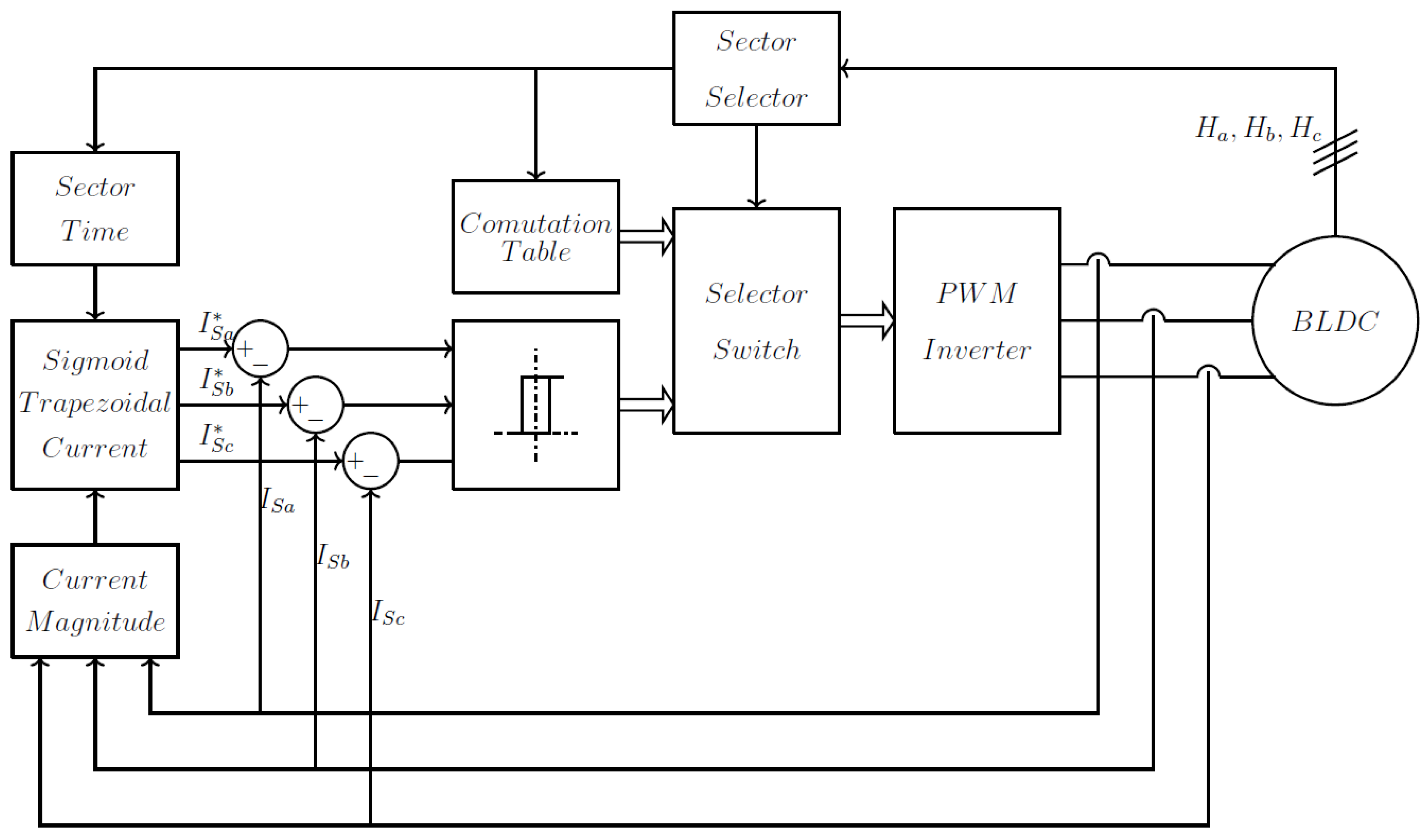
The block diagram for the
Sigmoid Trapezoidal Current Hysteresis Control demonstrates a precise method for regulating current in a BLDC motor. The
Sector Time block determines the timing of each commutation sector to synchronize the motor’s electrical phases with the rotor’s position. The
Sigmoid Trapezoidal Current block generates the reference currents (
) with soft transitions between the rising, flat, and falling segments, governed by a sigmoid function. This design minimizes sudden current variations, reducing torque ripple and harmonic distortion, thereby ensuring motor performance.
Figure 5 shows the control block diagram of the Proposed Sigmoid Trapezoidal Current Hysteresis Control.
- 3.
Current Hysteresis Control
The system continuously compares the actual phase currents () with the reference values to compute the error. This error signal is processed by the Commutation Table and Selector Switch, which control the PWM Inverter. The inverter modulates the currents in realtime, enabling accurate tracking of the reference waveform. The Sector Selector identifies the active commutation sector based on rotor position signals () to maintain proper phase alignment. This feedback loop adjusts the inverter’s output dynamically to ensure stable and efficient motor operation. The integration of the sigmoid trapezoidal current profile significantly improves the BLDC motor’s performance.
4. Simulation Results
The simulation serves as a vital tool for evaluating the performance and feasibility of the Sigmoid Trapezoidal Current Hysteresis Control strategy for the BLDC motor. Through simulation, the dynamic behavior of the control method is rigorously examined across various operating conditions, including load fluctuations, speed variations, and commutation events. In the simulated environment, the BLDC motor’s operation is replicated by incorporating essential components like the PWM inverter, current controllers, sector selection logic, and the sigmoid trapezoidal current generator. This virtual setup provides a realistic framework for assessing system behavior. Performance parameters such as current waveforms, torque ripple, phase synchronization, and harmonic distortion are thoroughly analyzed, ensuring the proposed control strategy meets the desired efficiency and operational standards.
Table 1 shows the BLDC motor specification.
The simulation results demonstrate the significant benefits of the
Proposed Sigmoid Trapezoidal Current Hysteresis Control compared to the
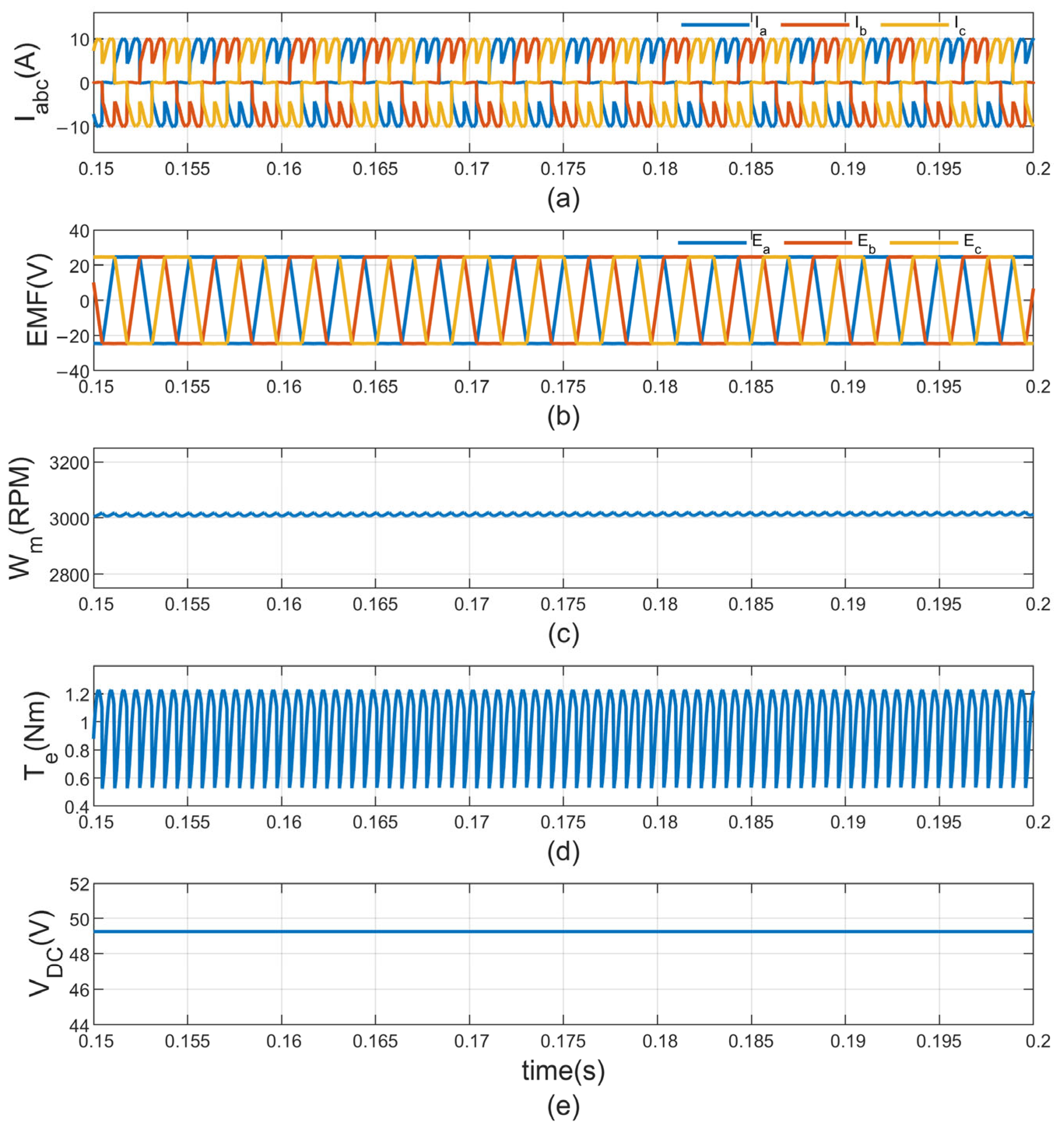
Traditional Electronic Commutation Control for a BLDC motor operating under full load conditions, with a torque of 1.27 Nm and a speed of 3000 rpm. In the conventional electronic commutation control approach, the BLDC motor operates under a mechanical load of 1 Nm with a constant 48 V DC input supply. Although the motor reaches the desired speed of 3000 rpm (
Figure 6c), it experiences noticeable speed fluctuations, indicating instability in speed regulation. The three-phase stator current (
Figure 6a) exhibits sharp transitions during commutation, resulting in significant current ripple. This, in turn, leads to pronounced torque ripple, measured at approximately 72.5%, corresponding to a variation of about 0.725 Nm from the average torque value (
Figure 6d), which negatively affects the motor’s smoothness and operational efficiency. Additionally, the three-phase back EMF (
Figure 6b) maintains a trapezoidal shape but lacks proper synchronization with the stator currents, leading to inefficient torque generation. Despite the stability of the input DC voltage (
Figure 6e), the overall power utilization is poor due to inefficient commutation and the presence of ripple, resulting in lower system efficiency and performance.
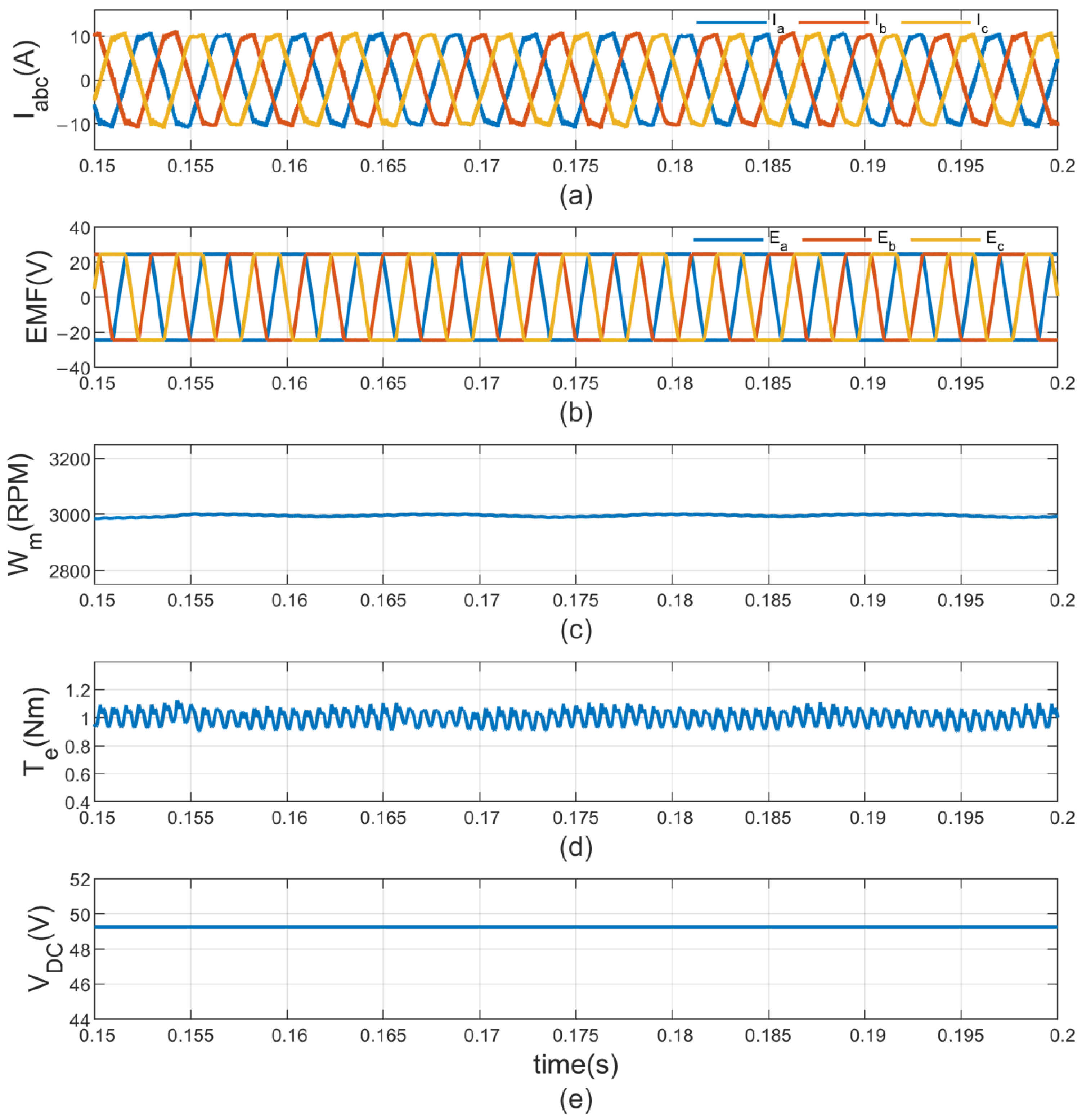
In contrast, the proposed Sigmoid Trapezoidal Current Hysteresis Control offers notable improvements in the performance of the BLDC motor operating under a mechanical load of 1 Nm with a constant 48 V DC supply. The three-phase stator current (
Figure 7a) transitions more smoothly during commutation, which significantly reduces current ripple and enhances the system’s stability. The three-phase back EMF (
Figure 7b) is well aligned with the corresponding phase currents, allowing for more efficient torque generation and better energy utilization. The motor speed (
Figure 7c) remains consistently close to the desired 3000 rpm with minimal speed fluctuations, reflecting precise control and steady operation. The torque output (
Figure 7d) is also more uniform, with the torque ripple reduced to approximately 13.67%, equivalent to a variation of about 0.137 Nm, resulting in more reliable motor performance. Additionally, the input DC voltage (
Figure 7e) stays constant at 48 V and is used more efficiently, contributing to improved overall system effectiveness and energy efficiency.
Table 2 presents a comparison of torque ripple for various commutation control methods applied to a BLDC motor at a 1 Nm load. The Proposed Sigmoid Trapezoidal Current Hysteresis Control notably reduces torque ripple from 72.5% (0.725 Nm) seen in conventional electronic commutation to just 13.7% (0.137 Nm). This significant decrease results in low torque ripple motor operation and higher efficiency, which is especially important for applications that demand steady torque and reduced vibrations. The Phase Advancing (PA) technique lowers torque ripple to 19.2% (0.192 Nm), while Phase Advancing with Overlapping (PAO) has a slightly increased ripple of 20.8% (0.208 Nm), both offering improvements over the traditional method. The simulation results demonstrate that the proposed control method enhances current waveform quality, speed consistency, and torque smoothness, thereby greatly improving the overall performance and reliability of the BLDC motor.
5. Conclusions
This paper introduces a novel approach to enhancing the performance of BLDC motors by reducing current harmonics and improving torque and speed stability. The proposed Sigmoid Trapezoidal Current Model, combined with hysteresis control, effectively stabilizes current transitions during phase commutation, significantly reducing harmonic distortion and mitigating the adverse effects of current ripple. Additionally, the integration of hysteresis PWM control optimizes the system by regulating the current and dynamically adjusting the switching frequency to ensure it stays within a specified range. Simulation results confirm the effectiveness of the proposed method, showing notable improvements in current waveforms, torque ripple, speed stability, and overall motor performance. The reduction in torque ripple from 72.5% to 13.67% highlights the benefits of this approach, ensuring refined motor behavior, improved efficiency, and enhanced reliability. These findings demonstrate that the proposed control strategy offers a promising solution for applications where consistent torque and reduced vibrations are essential, such as electric vehicle applications.

 and
and 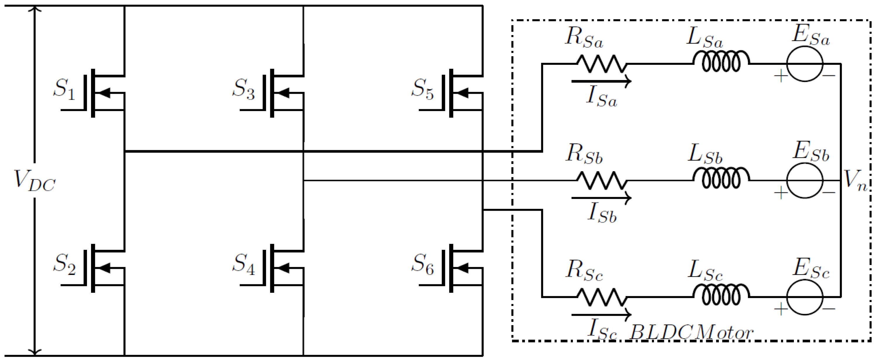
