Abstract
Due to climate change, the electric vehicle (EV) industry is rapidly growing and drawing researchers interest. Driving conditions like mountainous roads, slick surfaces, and rough terrains illuminate the vehicles inherent nonlinearities. Under such scenarios, the behavior of power sources (fuel cell, battery, and super-capacitor), power processing units (converters), and power consuming units (traction motors) deviates from nominal operation. The increasing demand for FCHEVs necessitates control systems capable of handling nonlinear dynamics, while ensuring robust, precise energy distribution among fuel cells, batteries, and super-capacitors. This paper presents a DSMC strategy enhanced with Robust Uniform Exact Differentiators for FCHEV energy management. To optimally tune DSMC parameters, reduce chattering, and address the limitations of conventional methods, a hybrid metaheuristic framework is proposed. This framework integrates moth flame optimization (MFO) with the gravitational search algorithm (GSA) and Fractal Heritage Evolution, implemented through three spiral-based variants: MFOGSAPSO-A (Archimedean), MFOGSAPSO-H (Hyperbolic), and MFOGSAPSO-L (Logarithmic). Control laws are optimized using the Integral of Time-weighted Absolute Error (ITAE) criterion. Among the variants, MFOGSAPSO-L shows the best overall performance with the lowest ITAE for the fuel cell (56.38), battery (57.48), super-capacitor (62.83), and DC bus voltage (4741.60). MFOGSAPSO-A offers the most accurate transient response with minimum RMSE and MAE FC (0.005712, 0.000602), battery (0.004879, 0.000488), SC (0.002145, 0.000623), DC voltage (0.232815, 0.058991), and speed (0.030990, 0.010998)—outperforming MFOGSAPSO, GSA, and PSO. MFOGSAPSO-L further reduces the ITAE for fuel cell tracking by up to 29% over GSA and improves control smoothness. PSO performs moderately but lags under transient conditions. Simulation results conducted under EUDC validate the effectiveness of the MFOGSAPSO-based DSMC framework, confirming its superior tracking, faster convergence, and stable voltage control under transients making it a robust and high-performance solution for FCHEV.
1. Introduction
Global environmental sustainability is facing issues due to the huge emission of carbon caused by diesel vehicles [1,2]. The increase in demand for fossil fuels in vehicles utilizing diesel fuel is a major concern for global climate issues [3]. Unlike fossil fuels such as diesel or natural gas, hydrogen is not abundantly available in its elemental form and must be produced using energy-intensive methods. With the global shift toward decarbonization, hydrogen has gained renewed attention especially in the form of green hydrogen produced via electrolysis using surplus renewable energy. This approach not only enables large-scale hydrogen production but also helps mitigate the intermittency of renewable sources such as solar and wind.
1.1. Environmental and Technological Aspects of Electric Vehicles
The transport sector is the biggest source of greenhouse gas emissions, and to resolve these issues, electric vehicles (EVs) have gained popularity across the globe because of their advantages like zero carbon emissions, low noise, light weight, better performance and efficiency [4]. EVs are classified as battery based electric vehicles (BEVs), fuel cell-based electric vehicles (FCEVs), and hybrid electric vehicles (HEVs) based on their energy sources. BEVs rely solely on batteries for power, whereas FCEVs use fuel cells to generate electricity. As a result, fuel cell electric vehicles (FCEVs) are being promoted as a promising clean transport solution, aligning with both energy storage goals and deep carbon reduction targets. HEVs and plug-in hybrid electric vehicles (PHEVs) combine internal combustion engines with electric propulsion to enhance efficiency and extend the driving range [5].
1.2. Motivation for Fuel Cell Hybrid Electric Vehicles
The motivation for fuel cell hybrid electric vehicles (FCHEVs) stems from the growing demand for zero-emission transport and the limitations of both battery electric vehicles (BEVs) and standalone fuel cell systems. While BEVs are limited by battery size, long charging times, and range constraints, and conventional fuel cell electric vehicles (FCEVs) face issues with fuel cell degradation and transient response, FCHEVs combine the strengths of both systems. By integrating fuel cells with batteries and/or super-capacitors, FCHEVs offer improved power delivery, energy recovery, and system efficiency, particularly in dynamic driving environments.
1.3. Hybrid Energy Storage and Power Converters in EVs
EVs utilize multiple energy storage devices (ESDs), including fuel cells (FCs), batteries, and super-capacitors (SCs), to meet diverse power demands. The fuel cell offers high efficiency with zero emissions but suffers from a slow transient response and voltage fluctuations, requiring DC–DC converters for regulation. Batteries provide high energy density but degrade over time, requiring efficient power management to prevent overcharging and extend the lifespan [6]. Meanwhile, super-capacitors excel in rapid charge–discharge cycles and handling sudden power surges, making them ideal for regenerative breaking, though their long-term energy storage is not optimal. A hybrid combination of FCs, batteries, and super-capacitors is essential to maximize efficiency and ensure reliable EV performance [7]. EVs integrate various energy storage devices (ESDs), such as FCs, batteries, and super-capacitors, connected through different types of power electronic converters to ensure efficient power delivery. Generally, ESDs are charged via the grid or charging stations using converters and subsequently supply the required energy to traction motors. However, ESDs exhibit nonlinear power behavior, voltage fluctuations, and considerable voltage drops, leading to power instability [5]. DC–DC converters contribute a crucial role in regulating the power flow, but their design is challenging due to dependencies on the voltage of the input side, the duty ratio, and load parameters. Additionally, these converters exhibit nonlinear behavior and lightly damped dynamics due to switching actions and complicated power-sharing and energy management. The complex interactions among power-producing units, power-processing units, and power-consuming units further impact system stability and performance, especially under varying driving conditions.
1.4. Literature Review
To address these challenges, advanced control strategies are crucial for precise voltage regulation, efficient power flow management, and maintaining optimal EV operation [8,9]. For obtaining a steady-state and dynamic response in EVs, the controller has the responsibility of having the fastest response, less settling time and less steady-state error [10,11]. Different variants of linear and nonlinear controllers are being used for controlling the duty ratio of the converter in EVs. Controllers of the linear type are simple and can be easily implemented; however, they are not effective under variations in system parameters [6]. These control techniques include the proportional integral derivative (PID), the linear proportional integral (PI), and the lead–lag compensator, and they have been widely used in DC–DC converter control as their implementation is simple. However, these methods rely on linear system assumptions, making them less effective for handling the nonlinear and time-varying nature of DC–DC converters. Moreover, they require precise parameter tuning and often struggle with disturbance rejection and robustness under varying operating conditions [12,13].
In the latest research, fuzzy-PID-MPC-based control techniques were applied to enhance the performance of fuel cell hybrid electric vehicles (FCHEV). To overcome these problems, controllers of the nonlinear type for FCHEVs are available in the literature, but these models incorporate sources of power and did not included the motor control part of the HEVs. In [14], the Lyapunov and Backsteping control technique for FCHEVs was presented. The nonlinear-type controllers perfectly track the current of energy sources and the speed of traction motors relative to their references by maintaining dynamic and asymptotic stability over a wider operational range. To overcome the limitations of the above-mentioned literature, sliding mode control (SMC) has gained significant attention due to its inherent robustness, fast dynamic response, and ability to handle model uncertainties. The coefficients of the controller have to be positive values and have an influence on the reachability and chattering. However, tuning the coefficients of sliding mode controllers is a challenging task, as several trials are needed to deal with above-stated difficulties [15], especially when considering switching-based control laws and highly dynamic driving profiles.
Over the years, several optimization techniques have been employed to fine-tune the parameters of SMC for better performance and robustness [16]. Classical methods such as trial-and-error tuning and heuristic approaches often lead to suboptimal results and require extensive manual effort. In contrast, there are metaheuristic optimization algorithms, like particle swarm optimization [16], the genetic algorithm (GA) [17], the gravitational search algorithm (GSA) [18], the butterfly optimization algorithm (BOA) [19], moth flame optimization [20], the whale optimization algorithm (WOA) [21], the salp swarm algorithm (SSA) [22], and enhanced whale optimization algorithm [23].
In this paper [24], an improved crayfish algorithm based on a multi strategy is proposed. This algorithm is leveraged together with the crayfish algorithm and various optimization techniques to overcome the shortcomings of conventional algorithms in local optima search and convergence speed, achieving parameter optimization of terminal sliding mode controllers in dynamic positioning-based systems. In [25], optimization by hybrid grey wolf optimization to improve the gains of sliding mode control based on an extreme learning machine is proposed to focus on uncertainties and external disturbances. In [26], grey wolf optimization is presented for second-order sliding mode control for the stabilization of an inchworm robotic manipulator. The controller has the capability to diminish the chattering.
Lately, in [27], a method of the sliding mode based on the extended grey wolf optimizer is proposed for controlling a 2-DOF robotic manipulator. Two PDs (proportional derivatives) and sliding mode control approaches were used and combined to benefit from the advantages of both controllers. Similarly, an energy storage system for a multi-source HEV based on super-twisting SMC has been proposed for the energy management of HEVs [28], which provides a stable and fast multi-objective optimization method for the energy management of HESS for EVs. A perturbation observer (P&O) energy scheme management control technique based on tuna swarm optimization (TSO) has been proposed for the HESS of EVs [29]. This method has reduced the quick charge loss of the battery and increased the lifetime of the battery used in the HESS. In [30], a robust sliding mode controller for EV motors has been developed to obtain motion control. In [31], a technique has been proposed using the chaos optimization algorithm and sliding mode controller to tackle the optimal control problems under uncertainty to minimize the cost function. In [32], a longitudinal type of controller for a passenger vehicle is presented, where particle swarm optimization (PSO) is applied to regulate the sliding surface and to tune the SMC gains. In [33], particle swarm optimization (PSO) is used to determine the optimal values of parameters in a sliding mode controller for a wheeled mobile robot, in order to achieve trajectory tracking with minimum chattering and maximum reaching rate. The study does not mention any limitations of the proposed method. In [34], a bidirectional DC–DC converter is managed using a hybrid particle swarm optimization (HPSO)-based fuzzy sliding mode controller. The proposed control strategy enables the DC–DC converter to achieve a low output ripple and maintain a stable voltage despite variations for various loads. In [35], the optimized coefficients of SMC using the bat algorithm was presented. The proposed control was designed to overcome the tracking issue in DOF SCARA robots. In [36], a method has been presented to improve the controller performance for an OSMC controller that is tuned by GA for the purpose of active suspension control in EVs.
All the literature presented above shows that these algorithms offer significant improvements by systematically searching for optimal parameter values; however, they often suffer from drawbacks such as premature convergence, high computational cost, and sensitivity to parameter selection. Furthermore, the stochastic nature of these optimization methods can result in inconsistent performance across different operating conditions. These limitations motivate the need for a more robust, efficient, and adaptive optimization framework tailored to the nonlinear dynamics of EVs.
1.5. Proposed Work and Contributions
This research introduces dynamic sliding mode control (DSMC) for dynamically adjusting the sliding surface integrated with a uniform exact differentiator, along with the moth flame optimization (MFO) framework hybridized with fractal heritage and entropy-based evolution for the improvement of system performance, offering a more robust and adaptive tuning approach for DSMC by improving convergence speed, global search capability, and control precision across nonlinear EVs system. The main contributions of this work are listed as follows:
- Proposed a nonlinear dynamic sliding mode control scheme integrated with uniform robust exact differentiators for the HESS and power stage of EVs.
- Integrating the fractional-order derivatives concept of particle swarm optimization (PSO) to modify the MFO update mechanism.
- Incorporating the gravitational search algorithm (GSA) into MFO to enhance search efficiency.
- Developed an innovative moth flame optimization framework hybridized with fractal heritage to optimally tune the DSMC control parameters, enhancing robustness and stability.
- Validated the proposed control scheme through MATLAB/Simulink simulations using an EUDC profile, demonstrating asymptotic stability of the closed-loop control system, effectively handling nonlinearities and dynamic variations in FCHEVs under external driving conditions.
The remaining part of this paper is organized as follows: Section 2 presents the detailed FCHEV system under study; Section 3 presents the FCHEV system’s mathematical modeling. Section 4 is titled Global/Generalized Model of FCHEV System. Section 5 introduces moth flame heuristics. Section 6 provides the design of the control strategy. Section 7 shows the results and simulation, and Section 8 is dedicated to discussion, with Section 9 concluding this paper.
2. FCHEV System Under Study
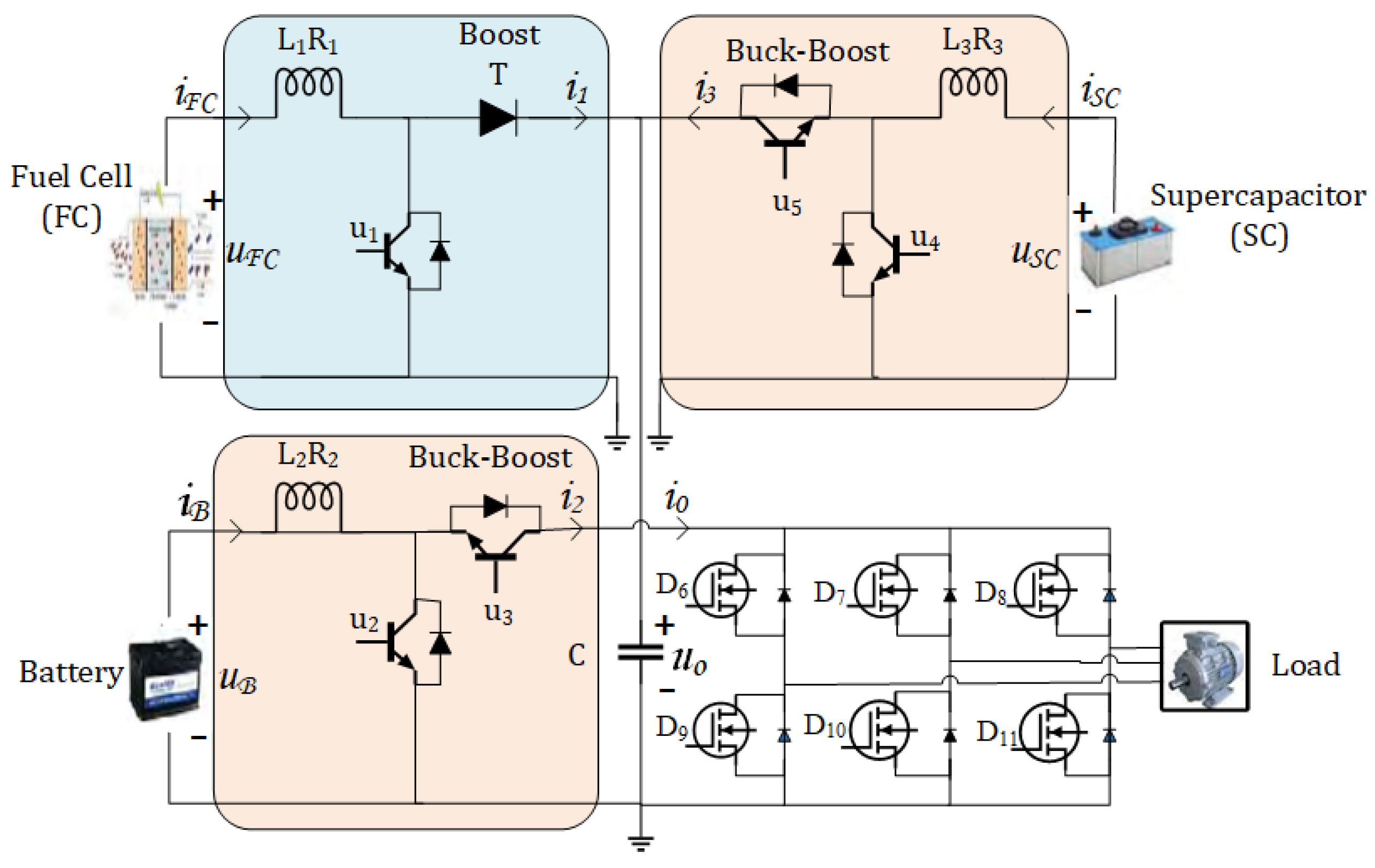
The hybrid ESDs, power converters (buck-boost), and electric traction motor are the major parts of the FCHEV as shown in Figure 1 below.
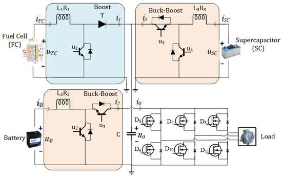
Figure 1.
Power processing block.
2.1. Hybrid Energy Storage Units
THe FCHEV consists of a FC, battery, and super-capacitor. The FC is used as the main source of power and is aided by the battery and super-capacitor.
2.1.1. Fuel Cell
In automotive applications, the FC provide numerous advantages, including greater efficiency, extended lifespan, compact size, lower operating temperature, and enhanced durability. To ensure its applicability, it is advantageous to use the FC with other power sources. This hybridization enables the system to leverage all the strengths of the FC as a power source while mitigating its inherent limitations. Characteristics such as high power density and the capability to efficiently recover regenerative energy make the SC a highly suitable component for integration in FCHEVs. Due to the delayed start-up of the fuel cell and the self-discharge characteristics of the SC, a battery becomes an essential component in FCHEVs to provide initial traction. Although batteries offer high energy storage capacity, their lifespan in terms of charge–discharge cycles is significantly shorter compared to the SC [5]. Furthermore, despite their efficiency, PEMFCs suffer from limited lifespan due to the degradation of catalysts, membrane damage, and operational stresses. These issues impede long-term reliability and commercial deployment. Recent studies also employ Transformer-based models to predict performance decline and optimize fuel cell lifespan. This updated perspective ensures a balanced comparison among all energy sources in the FCHEV system.
2.1.2. Super-Capacitor
A super-capacitor is being employed between capacitors and batteries, having higher capacitance. Super-capacitors are very effective for storing the electrical energy. They have higher power density and can store maximum energy from regenerative breaking, such that a super-capacitor is suitable for FCHEV applications [37].
2.1.3. Battery
For EVs, the application of batteries plays an important role due to their higher energy density for the storage and discharging of electrical energy. The problems of slow starting and discharging of an FC battery is required in FCHEVs for the initial stage. On the other hand, batteries have higher energy densities, but their operating cycles are extremely limited as compared to super-capacitors [37].
2.1.4. Electric Traction Motor
The electric traction motor comprises a part of the utmost significance for the development of electrified transport. The electric propulsion system is a major part of EVs and HEVs. The use of a propulsion system is dependent on many factors like vehicle parameters, the driver’s operational requirements, and the type of energy sources. Many different types of traction motors are available in the market, but the selection of any specific motor for the propulsion system depends on its structure, ruggedness, light weight, low cost, flexible electric drive control, fault tolerant capability, low acoustic noise level, better start-up torque, high efficiency and high power density, and constant torque and constant power regions over a wide speed range [38].
3. FCHEV System Mathematical Modeling
The FCHEV-based ESDs mathematical modeling is given in this section. The power processing block is given in Figure 1 [39].
3.1. Fuel Cell Modeling
The fuel cell mathematical model is given below:
3.2. Battery Energy Storage Modeling
The battery is lined with the DC–bus with a buck-boost converter and it operates in the boost mode of operation during discharge and in the buck mode during charging. The mathematical model for both modes of operations are given below [40]:
3.2.1. Boost Mode of DC–DC Converter
3.2.2. Buck Mode of DC–DC Converter
3.3. Super-Capacitor Modeling
The super-capacitor is linked to the DC-bus with a buck–boost converter, and its operation is in boost mode during discharge and in buck mode while charging [40]. The mathematical models for both modes of operations are given below:
3.3.1. Boost Mode of DC–DC Converter
3.3.2. Buck Mode of DC–DC Converter
3.4. Electric Drive Train Modeling
In FCHEVs, a three-phase induction type motor is utilized for the purpose of propulsion for the tracking of EV speed under varying loads [14]. For the purpose of mathematical modeling in rotating frame dq-axis transformation is used and given as follows:
where as
and
- current of stator in d-axis component.
- current of stator q-axis component.
- d-axis component of rotor flux.
- q-axis component of rotor flux.
- frequency of stator.
- angular speed.
- load torque.
- number of pole pairs.
- resistance of rotor.
- resistance of stator.
- self inductance of rotor.
- self inductance of stator.
- stator and rotor windings mutual inductance.
- viscous damping coefficent.
- motor inertia and load.
The output voltage, inductor current, and the stator components are related with each other as given by the following equation:
The relationship between stator voltages and output voltage are given as follows:
4. Global/Generalized Model of FCHEV System
The overall model of FCHEV system is given below:
5. Moth Flame Heuristics
Nature-inspired optimization algorithms are significant due to their effectiveness in solving optimization problems [41,42]. Among these, optimization by the moth flame algorithm has been widely used for its exploration balance and success in nonlinear control applications. However, like many metaheuristic algorithms, MFO suffers from convergence that is premature and stagnation in local optima. To address these limitations, various hybridization strategies have been explored to enhance its performance. In this work two novel hybrid schemes are proposed: (i) integrating the fractional-order derivatives concept of particle swarm optimization (PSO) to modify the MFO update mechanism, and (ii) incorporating the gravitational search algorithm (GSA) into MFO to enhance search efficiency. The fractional-order MFOPSO () leverages the memory effect and hereditary properties of fractional calculus, allowing for a more adaptive and dynamic search process.
Meanwhile, the GSA-assisted () method combines the stochastic nature of MFO with the gravitational search principles of GSA, leading to improved exploration and exploitation capabilities. These algorithms were chosen based on criteria including search diversity, convergence stability, and suitability for high-dimensional controller tuning. Furthermore, our literature review confirmed that this specific MFOPSOGSA hybrid has not been previously applied to FCHEV control systems, making our approach both novel and well founded. Similarly, the proposed MFO variants are compared with GSA and PSO techniques, and a detailed discussion is given in Section 7.
Mirjalili [43] is the pioneer in introducing the MFO algorithm, inspired by the transverse positioning of moths during nocturnal navigation. Unlike the other algorithms mostly found in the literature, the MFO method emulates a mathematics model that replicates dying behavior via the use of spiral type trajectory functions. The moths employ a transverse strategy at night, maintaining a constant angle relative to the moonlight to navigate more directly across extended distances. At night, the presence of artificial illumination or flames often leads to the deviation of moths from their planned course. So it transpires that the proximity of moths to artificial sources of fire is less than that to moonlight. They become trapped in a fatal spiral pattern around the light source by maintaining a constant angle relative to it, eventually resulting in their mortality as they descend towards the light source [44].
The MFO algorithm is a population-based search method. Each moth operates as a search agent in this system, and the position of each search agent represents the aggregate number of controllable variables. This technique aims to discover the solution that is most optimum. A framework illustrating a preliminary solution of moths M, including n potential solutions and dimensions d related to controlled variables, is executed via a necessary objective function, based upon the fitness of each candidate solution recorded in the matrix [20,45] .
A matrix analogous to that of moths is generated for flames F, with fitness values appropriately recorded in . Moths are drawn to flames, and the other search agents adjust their placements depending on the optimal position attained by a search agent to date [20].
The location of each moth relative to the flame is adjusted using the spiral function S.
A distinct variant of the swarm algorithm is the GSA, which is based on gravitational law. In contrast to PSO, the GSA approach takes fitness values and solution quality into account when the agent positions are being updated. This gives the GSA algorithm an advantage in finding the optimal solution more quickly. The GSA’s velocity is independent of past best solutions. Conversely, the current velocity will be determined by the individual force of other particles acting on an agent as well as the current best and worst fitness response.
In a GSA including n agents, each agent is allocated an initial inertial mass, M. The cumulative force exerted on the mth agent is as follows:
Here, denotes the active gravitational mass associated with agent n, represents the passive gravitational mass linked to agent m, signifies the gravitational constant at time t, is a negligible constant, and indicates the Euclidean distance between agents i and j. The is computed as follows:
where is a descending coefficient. In a problem space represented by dimension k, the total acting force on agent m is determined as illustrated in Equation (44).
Based on Newton’s law of motion, the object accelerated proportionally to the resultant forces, and its mass is inversely proportional; so, the acceleration of all objects should be computed as shown:
where t denotes a certain time, and represents the mass of item m. The agents’ velocity and location are computed as shown in Equations (46) and (47).
This study signifies a significant shift from traditional techniques by combining the optimization potential of a nature-inspired algorithm with the distinctive features of fractional-order calculus and GSA. MFO has significant promise for global exploration; nevertheless, its insufficient local search skills lead to a substantial reduction in the convergence rate. The use of FC and GSA in several scientific disciplines has garnered significant interest from scholars. The concept of FC may be expressed in several ways. The theoretical equations for MFO, based on FC principles, may be constructed using the Grünwald–Letnikov model. Examine any stochastic signal , the Grünwald Letnikov fractional-order derivative is defined as follows:
The Euler gamma function is expressed as , and the incremental time step is indicated by h. All prior movements are intrinsically preserved by fractional derivatives. The calculation in discrete time relies on the formula specified in Equation (48).
In the specific scenario when , Equation (48) is reformulated into a first-order integer derivative, as shown in Equation (50).
The current velocity of the mth moth is modified by including acceleration into the existing velocity, as seen in Equation (51).
The location of the mth moth is updated by adding the velocity to its current position, as seen in Equation (52).
The distinctive attribute of () is determined by the global search approach used by PSO motion, whereas the local search methodology is based on the FC and GSA algorithms. The moth’s position is adjusted at each iteration, using its current velocity and location. The starting velocity and the cognitive and social behavioral traits of moths are associated with the modified velocity. The mathematical representation of cognitive behavior indicates the acceleration of each moth, whereas social behavior reflects the difference between the global optimal flame and the current positions of the moths, as shown in Equation (53).
signifies the velocity of the mth particle at the current iteration , whereas indicates the velocity at the prior iteration. denotes the global optimal location of the mth flame. and represent the cognitive and social behaviors of search agents. and are stochastic variables uniformly distributed throughout the interval . denotes the acceleration of the mth search agent at time t, computed as specified in Equation (53), and is restructured as shown in Equation (54).
The equation represents the integer’s first-order difference, which has the fractional-order derivative fixed at 1, thereby constituting a conventional integer order derivative. Inserting into Equation (48) produces the equation outlined in Equation (55).
The numerical value of a velocity derivative may be normalized to a real number between zero and one, leading to more uniform fluctuations and an improved memory effect, according to FC ideas. Considering the discrete-time fractional differential, the equation may be reformulated as shown in Equation (56) [20].
5.1. Logarithmic Spiral Trajectory Function
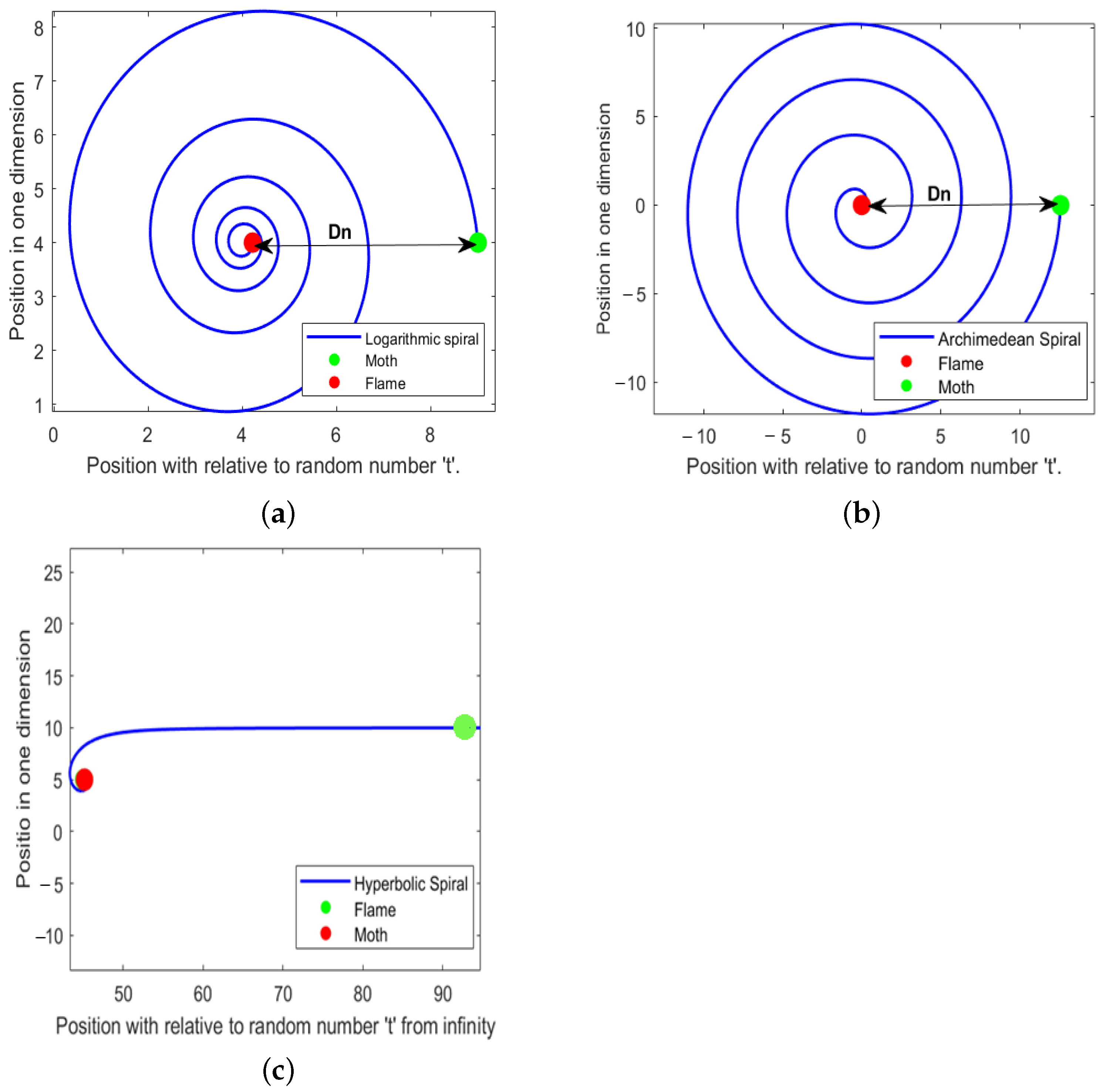
Conventionally, the MFO algorithm simulates the spiral trajectory of moths using a logarithmic spiral function showing in Figure 2, with its directionality refined as described in Equation (57).
In Equation (57), represents the linear distance that separates the nth moth and the nth flame, where a denotes the shape factor of the logarithmic spiral, and t is a random variable ranging from to 1. The logarithmic spiral function underpins the balance between exploration and exploitation, as moths constantly adjust their locations in relation to flames by circling them. Exploration transpires when the continuous movement of the agent remains external to the search space for the moth along with the flame, while exploitation occurs when the movement of the agent is contained inside the search space. The randomly generated t signifies the extent to which the accelerated positions of moths approach flames.
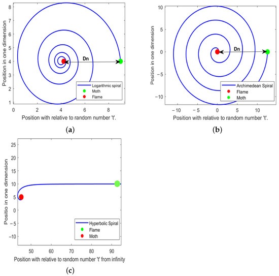
Figure 2.
Trajectories of moth: (a) logarithmic, (b) archimedean, and (c) hyperbolic.
The original MFO method demonstrates that the transverse orientation behavioral patterns of moths is the primary factor that replicates their movement in the hyper spherical space surrounding flames. The initially developed MFO algorithm used a logarithmic spiral to represent the spiral trajectory of moths around flames. In our study, we aimed to explore other spirals and examine the efficacy of the modifications in the initially developed MFO algorithm via a series of trials [46].
5.2. Archimedean Spiral Trajectory Function
The Archimedean spiral is a curve that originates at the origin and forms many revolutions, maintaining a constant distance between its branches. The distances of junction points along a line originating from the origin are uniform and characterized by a polar equation of the following form [46]:
Numerous values of n yield distinct spirals, with n serving as a constant that dictates the tightness of the spiral’s wrapping. In the original MFO algorithm, we replaced the logarithmic spiral function with our archimedes spiral function and modified it to represent the moth’s traversal around the flame in a specified direction [46] as shown in Figure 2.
5.3. Hyperbolic Spiral Trajectory Function
This updated version of the MFO algorithm utilizes the hyperbolic spiral, which is a transcendental-type plane curve also referred to as a reciprocal spiral. It contrasts with an archimedean spiral, possessing an inversion center at the origin, and it is classified as a type of cotes spiral. The hyperbolic (reciprocal) spiral commences at an infinite distance from the pole at the center (commencing from zero, begins at infinity) and accelerates its spiraling path as it nears the pole; the distance from any point along the curve to the pole remains infinite, as illustrated in Figure 2, which depicts the reciprocal spiral and its properties [46].
In the original MFO algorithm, we may update it to represent the moth’s excursion around the flame with a specified directional by substituting the reciprocal hyperbolic function for the logarithmic spiral function.
6. Design of Control Strategy
6.1. Robust Uniform Exact Differentiator
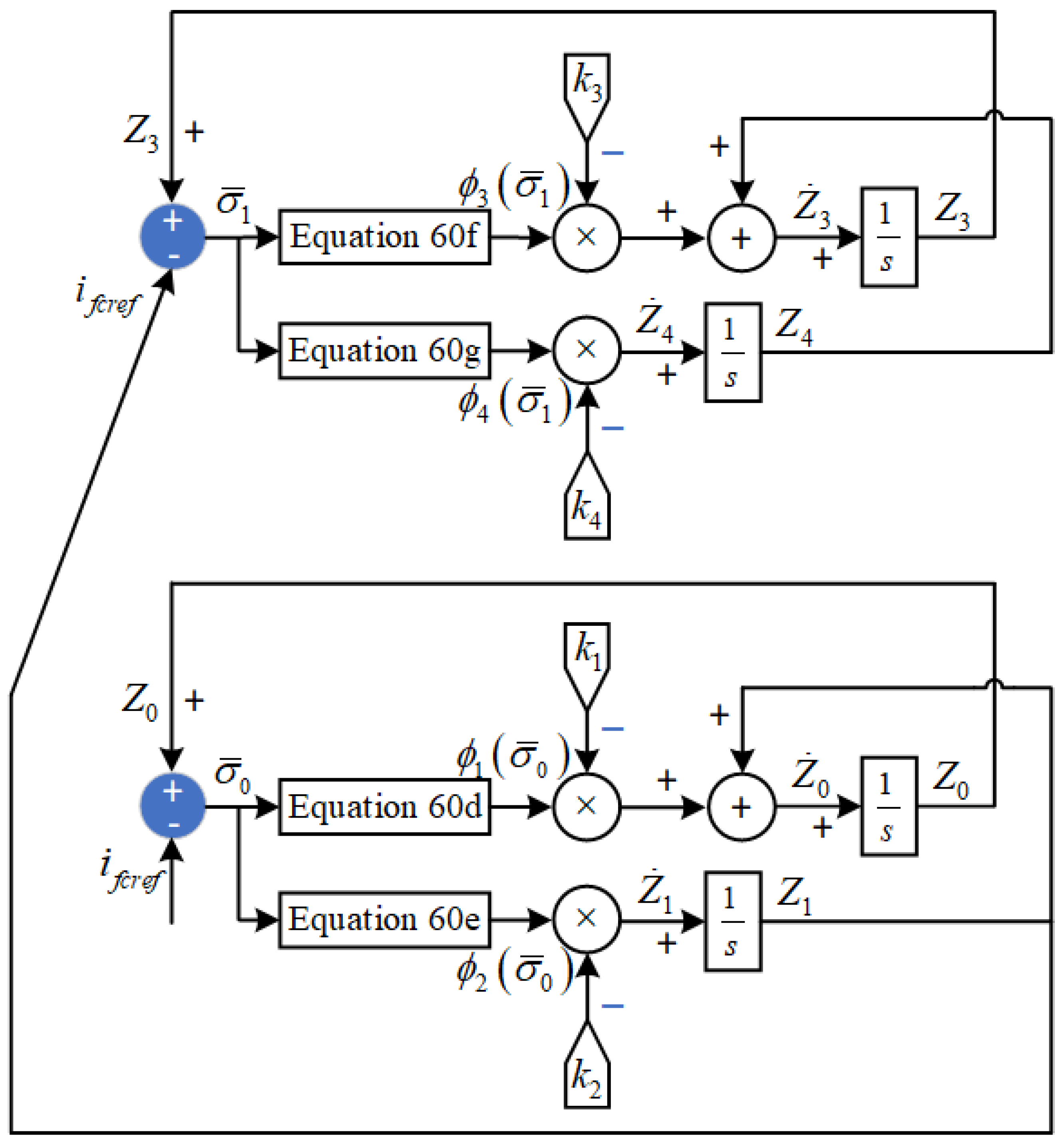
The robust uniform exact differentiator as shown in Figure 3, is normally utilized in higher-order variants of SMC. It is used when the derivatives are not directly measurable, with bounded disturbances and infinitesimal noises. Supposing that for a given signal the derivates are Lipschitz continuous, then it is defined as follows:
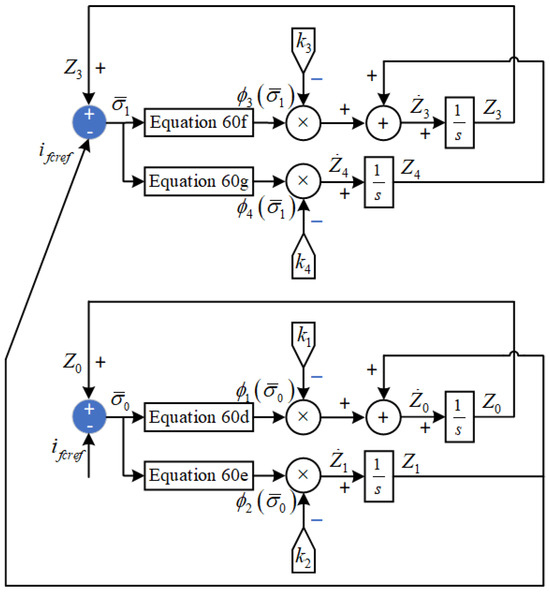
Figure 3.
Robust uniform exact differentiator.
6.2. Control Law Formulation
Dynamic sliding mode control is proposed in this research to improve the performance and to eliminate the effect of the chattering. DSMC strategies definitely gave results with substantially smoothed control input signals, hence the possibility of chattering-free controlled responses. DSMC also provides an improvement in system stability by getting better system performances even under disturbances or parametric variations. However, limitations include high computational complexity, and the optimization process requires significant time.
6.2.1. DSMC for Fuel Cell
The derivation begins by defining the tracking errors for the fuel cell current and DC bus voltage along with their time derivatives. These errors are then expressed using the system dynamics by substituting the state equations, leading to Equations (64)–(68). The sliding surface is constructed by combining the current and voltage error dynamics, and its time derivative in Equation (70) forms the foundation for the control law design. This formulation ensures that the control inputs are derived based on measurable states, supporting both theoretical analysis and practical implementation. The error dynamics for FC current tracking is defined as follows:
Now, inputting the value of Equation (28) into Equation (62), we obtain the following:
Taking the time derivative of Equation (28) and putting it in Equation (63), we obtain the following:
As the DC bus voltage is defined as , its error dynamics and its first time derivatives are defined as follows:
Now, by inputting the values, Equation (67) is expressed as follows:
The sliding surface and its time derivative are defined as follows:
and
Now, inputting the values in Equation (70), we obtain the following:
The reachability condition is defined as follows:
Given the dynamics of from Equation (72) and applying the term from Equation (73), after comparing and simplifying, we obtain the control law for the fuel cell:
In Equation (74), and are given by a uniform exact differentiator. Similarly, the stability analysis is performed using the Lyapunov candidate function:
must be negative definite for system stability. To ensure stability, we calculate the time derivative of , denoted , as follows:
After putting the values from Equation (72) into Equation (76), we obtain the following:
Since is greater than zero, the stability of the fuel cell is satisfied.
6.2.2. DSMC for Battery Energy System
The error dynamics for battery current tracking are defined as follows:
Now, inputting the values into Equations (79) and (80), we obtain the following:
similarly
The sliding surface and its time derivative are defined as follows:
Now, inputting the values into Equation (84), we obtain the following:
The reachability condition is defined as follows:
Given the dynamics of from Equation (85) and inputting it into Equation (86), after comparing and simplifying, we obtain the control law for the battery:
In Equation (87), and are given by a uniform exact differentiator. Similarly, the stability analysis is performed using the Lyapunov candidate function:
must be negative definite for system stability. To ensure stability, we calculate the time derivative of , denoted , as follows:
and
Since is greater than zero, the stability of the battery is satisfied.
6.2.3. DSMC for Super-Capacitor
The error dynamics for super-capacitor current tracking are defined as follows:
Now, inputting the values into Equations (92) and (93), we obtain the following:
similarly
The sliding surface and its time derivative are defined as follows:
Now, inputting the values into Equation (97), we obtain the following:
The reachability condition is defined as follows:
Given the dynamics of from Equation (98) and inputting it into Equation (99), after comparing and simplifying, we obtain the control law for the super-capacitor:
In Equation (100), and are given by a uniform exact differentiator. Similarly, the stability analysis is performed using the Lyapunov candidate function:
must be negative definite for system stability. To ensure stability, we calculate the time derivative of , denoted , as follows:
and
Since is greater than zero, the stability of the SC is satisfied. The second order dynamic mode for the DC link voltage is given below:
6.2.4. DSMC for Induction Motor
To minimize the error of the d-axis rotor flux and the speed of the motor, the error dynamics are defined as follows:
where and are corresponding reference values. The controller is computing reference values for d-axis and q-axis stator currents, represented by and , also known as virtual control inputs. So, the error dynamics are defined below:
Now, the desired dynamics are chosen as shown below:
Now, inputting values into Equations (108)–(111), we obtain the following:
Selecting and as virtual control inputs from Equations (112) and (113), the desired or reference state variables and are defined as follows:
The sliding surface and its first time derivatives are defined as follows:
After inputting values into Equation (118a), we obtain the following:
The reachability condition is defined as follows:
Now, by substituting the value of in Equation (120), and after simplification, the control law for is defined as follows:
In Equation (121), and are given by a uniform exact differentiator. Similarly, the stability analysis is performed using the Lyapunov candidate function:
must be negative definite for system stability. To ensure stability, we calculate the time derivative of , denoted , as follows:
and
Since is greater than zero, the stability is satisfied. Now, the sliding surface for obtaining the control law for is defined as follows:
After inputting the values into Equation (126), we obtain the following:
The reachability condition is defined as follows:
Now, by substituting the value of in Equation (128), and after simplification, the control law for is defined as follows:
In Equation (74), and are given by a uniform exact differentiator. Similarly, the stability analysis is performed using the Lyapunov candidate function:
must be negative definite for system stability. To ensure stability, we calculate the time derivative of , denoted , as follows:
and
Since is greater than zero, the stability is satisfied. For each control loop fuel cell, battery, super-capacitor, and induction motor, we defined explicit Lyapunov candidate functions of the form , where represents the sliding surface. The time derivative of each Lyapunov function, , is shown to be negative definite under the reachability conditions , where . As demonstrated in Equations (77), (90), (103), (124), and (132) of this manuscript, holds with appropriately selected positive gains, thus satisfying Lyapunov’s direct method for asymptotic stability. This rigorous mathematical treatment supplements the simulation validation, fulfilling the theoretical stability requirements expected in robust control design.
6.3. Tuning Problem Formulation
Although sliding mode control strategies have shown promising performance in both regulation and tracking frameworks in electric vehicle applications, these switching-based approaches require the effective tuning of coefficients of manifolds and discontinuous signum functions of switching control laws, which is a cumbersome design process. The tuning of these sliding manifold-based switching control schemes demands an automated and systematic objective function optimization-based design procedure to effectively explore the multi-dimensional parameter search space.
For the control laws given by Equations (74), (87), (100), (121), and (129), the design of dynamic SMC systems involves the tuning of five subsets of unknown parameters. For the i-th control law, the parameter subset is denoted as . The selection of these parameters is hard and time-consuming. Since the iterative trials and errors are a time-consuming, laborious task which does not guarantee a robust and stable solution, the tuning of such a complex and large-scale problem is formulated as a constraint-based optimization problem as follows:
Minimize the objective function , where
with
In this work, the weighting coefficients are taken equal to unity, i.e., .
The search space S is defined as follows:
subject to the following:
7. Simulation Results and Analysis
The FCHEV along with the proposed control system was implemented in MATLAB/Simulink R2023a on a 13th generation desktop with 64 GB RAM. The model comprises two main subsystems: a power converter control loop and a motor control loop under the EUDC profile that is a replication of city driving conditions with high speed, with a maximum speed limit of 90 km/h and an EUDC profile duration of 400 s. The proposed hybrid optimization algorithms were evaluated against conventional GSA and PSO approaches, with a detailed comparative analysis presented in this section. Appendix A shows the specification values of the sources, power, and induction motor.
7.1. Power Converter Control Loop
The main purpose of this loop is to ensure that the current of energy sources tracks their references along with their DC bus voltage that is set to a fixed reference (in the presence of load-side power demands). This loop produces control signals for the energy sources converters, i.e., for the FC converter, for the battery converter, and for the SC converter, respectively, as shown in Figure 1.
7.2. Traction Motor Control Loop
The purpose of this control loop is to track the speed of vehicle to the EUDC driving profile. The control signals and are used for the three-phase inverter so that the inverter can control the motor input currents and by applying correction voltages and across the input of the stator. To power up the traction motor against load torques, the following equations are utilized to calculate the power demand for the load current from the DC bus.
The parameters of the above equation are defined as follows:
- standard air density;
- vehicle speed;
- rolling resistance coefficient (0.01);
- frontal area of the car (1.8 m2);
- mass of the car (1066 kg);
- constant of gravitational acceleration;
- aerodynamic drag coefficient (0.19);
- Voltage of the DC bus → 400 V.
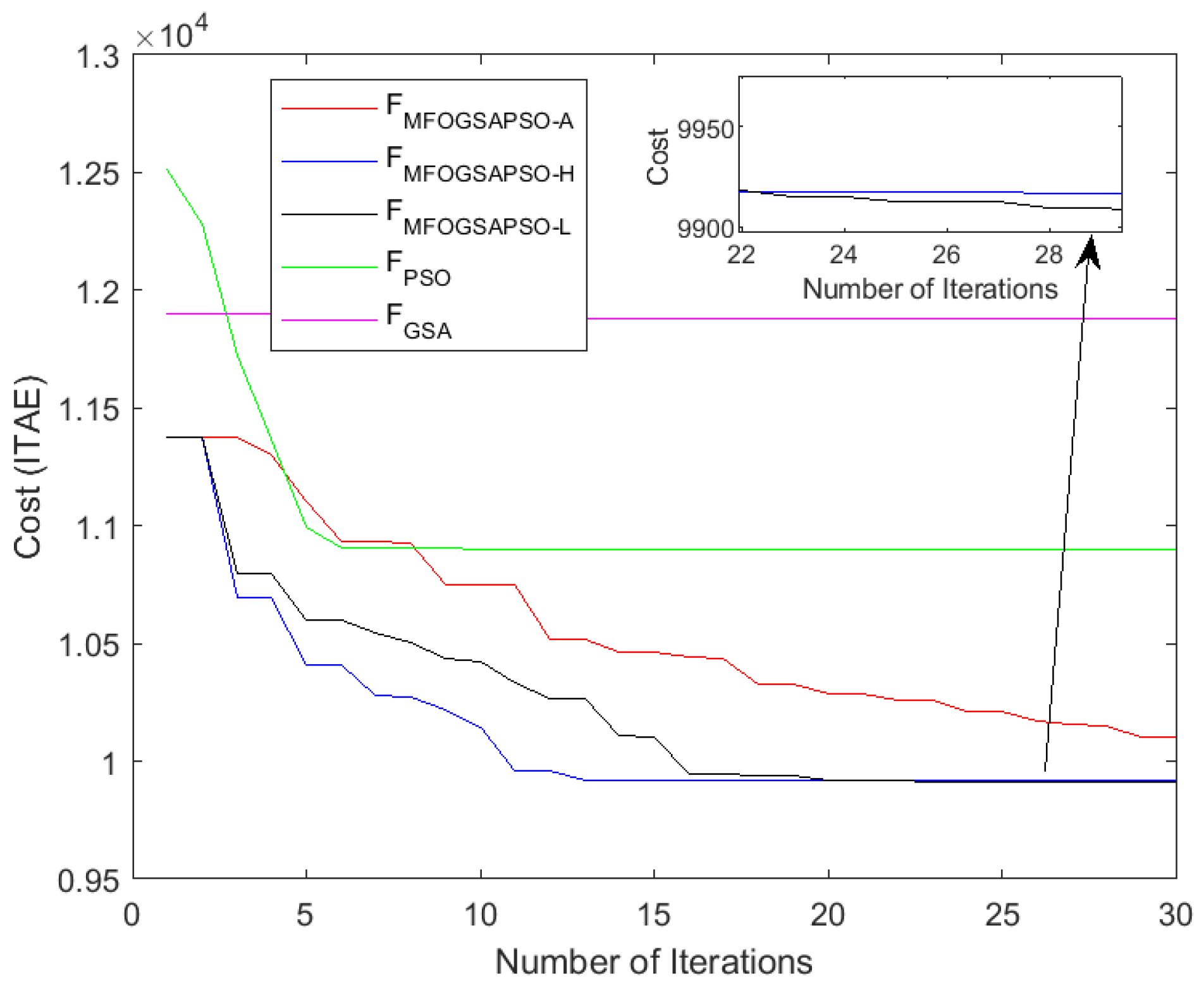
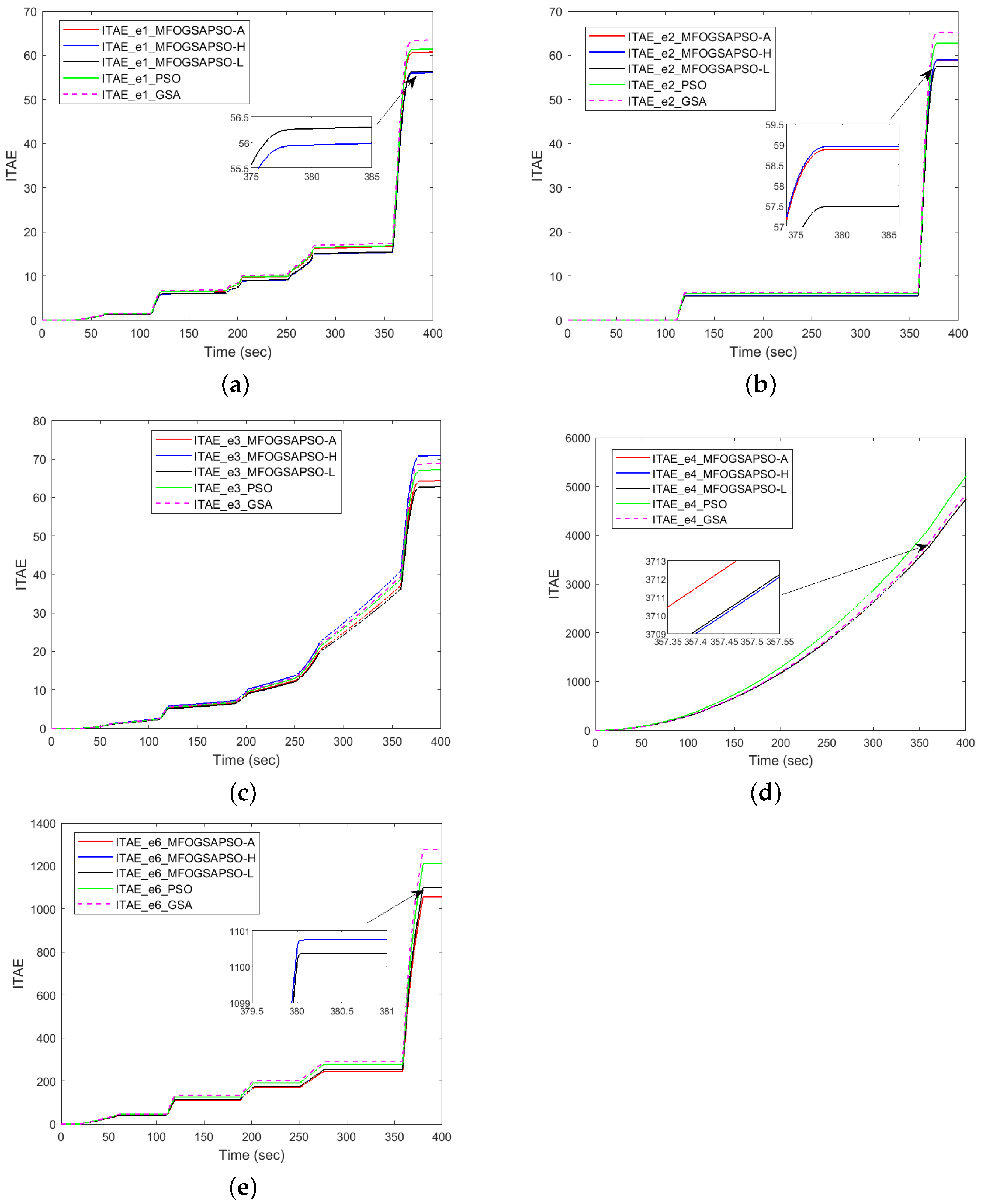
The objective function given in Equation (133) is formulated as the integral of time absolute errors (ITAEs) for five performance-related tracking signals. It steers errors more heavily, encouraging fast and accurate convergence of the controller outputs to their references. The cost convergence plot presented in Figure 4 illustrates the objective function evaluation of three MFOGSAPSO variants as well as PSO and the GSA in minimizing this multi-objective error function.
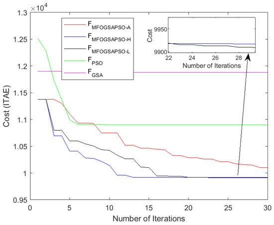
Figure 4.
Cost function vs. iterations.
Among the techniques, MFOGSAPSO-H exhibits the fastest convergence and lowest final cost value, showing its effectiveness in early-stage exploration and precise exploitation phases. MFOGSAPSO-L also performs competitively, maintaining consistent cost reduction and achieving a nearly identical final cost as the hyperbolic variant, though with a slightly slower convergence rate. On the other hand, MFOGSAPSO-A shows a smoother but more gradual decline in the cost function, converging to a higher final ITAE value compared to its counterparts. This implies that while the adaptive variant promotes stable parameter evolution, it may underperform in terms of aggressive cost minimization.
In comparison, PSO demonstrates moderate performance with early improvements but plateaus quickly, indicating limited exploitation capability. The GSA, on the other hand, shows the slowest convergence and highest final cost, reflecting weaker exploration and local search efficiency.
7.3. Performance Indices Evaluation
The performance indices are shown in Figure 5 and numerical values are given in Table A4 for () and Table A5 for (), with a comparison in Table A6. While integer-order methods may seem slightly more efficient based on ITAE alone, fractional-order formulations outperform them in practical control performance, as indicated by a lower RMSE and MAE. Integer-order () methods show slightly better convergence (lower ITAE) in a few cases but at the cost of higher noise sensitivity and tracking error. Fractional-order methods (Table A4) produce more consistent and stable responses, with better transient smoothness and a lower RMSE/MAE and are particularly beneficial under nonlinear, highly dynamic conditions.
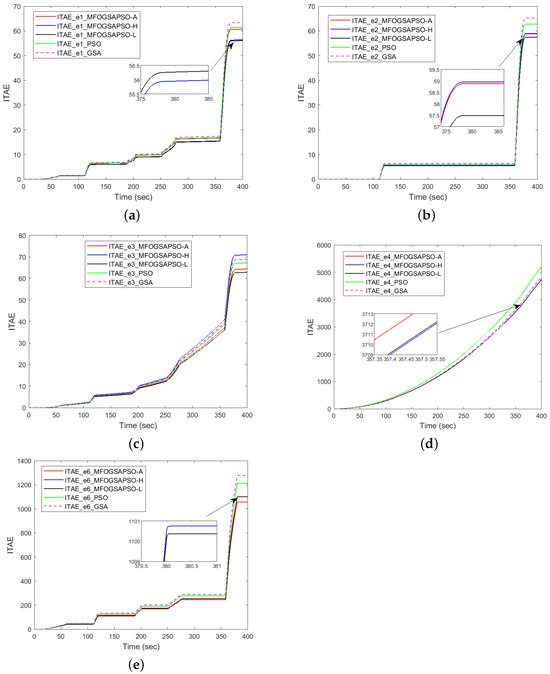
Figure 5.
ITAE-based dynamic performance indices.
Refer to Table A4 for numerical values of ITAE and plots are shown in Figure 5. Figure 5a shows FC tracking, MFOGSAPSO-L achieves the lowest ITAE of 56.389856, followed closely by MFOGSAPSO-A at 59.870123. PSO and the GSA perform worse with ITAE values of 61.235678 and 63.452341, respectively, while MFOGSAPSO-H lies in between at 60.678476. In battery tracking (Figure 5b), MFOGSAPSO-A achieves the ITAE of 58.112345, slightly better than MFOGSAPSO-H (58.881124), but MFOGSAPSO-L achieves the best results (57.487649), whereas PSO (60.08349) and GSA (65.273210) show higher values. Figure 5c shows SC tracking, MFOGSAPSO-L records the lowest ITAE at 62.836099, followed by MFOGSAPSO-A (63.164579) and H (64.402142), while PSO (65.112234) and the GSA (68.878172) again perform the worst.
In DC bus voltage tracking seen in Figure 5d, all MFOGSAPSO variants show competitive ITAE values around 4739–4744, with MFOGSAPSO-A achieving the lowest at 4739.812345. PSO (4770.451124) and the GSA (4839.196470) show less effective control. In the case of speed tracking given in Figure 5e, MFOGSAPSO-A outperforms all others with the lowest ITAE of 1052.112347, while MFOGSAPSO-H and L yield higher values of 1056.606534 and 1100.365356, respectively. PSO (1175.112233) and the GSA (1276.189428) show the least favorable performance. In terms of transient accuracy, MFOGSAPSO-A achieves the lowest RMSE and MAE for FC tracking (RMSE = 0.005712; MAE = 0.000602), SC tracking (RMSE = 0.002145; MAE = 0.000623), battery tracking (RMSE = 0.004879; MAE = 0.000488), DC bus voltage tracking (RMSE = 0.232815; MAE = 0.058991) and speed tracking (RMSE = 0.030990; MAE = 0.010998), highlighting its superior response.
MFOGSAPSO-H, on the other hand, consistently balances low ITAE with a favorable RMSE and MAE values for the FC, battery, SC, and speed tracking, and MFOGSAPSO-L achieves a low RMSE and MAE for DC bus voltage tracking. On the other hand, PSO generally performs moderately but trails behind MFOGSAPSO variants in most metrics, while the GSA consistently shows the highest RMSE and MAE, indicating the least effective overall control. The GSA tends to exhibit premature convergence, often failing to reach the optimal solution due its premature convergence. The MFOGSAPSO variants demonstrate faster convergence, enabling quicker attainment of optimal solutions. In contrast, PSO typically starts with very high initial cost values and converges more slowly compared to the MFO variants. The MFOGSAPSO variants, however, achieve optimal solutions in fewer iterations, highlighting their efficiency and superior convergence performance.
7.4. Evolution of DSMC Gains
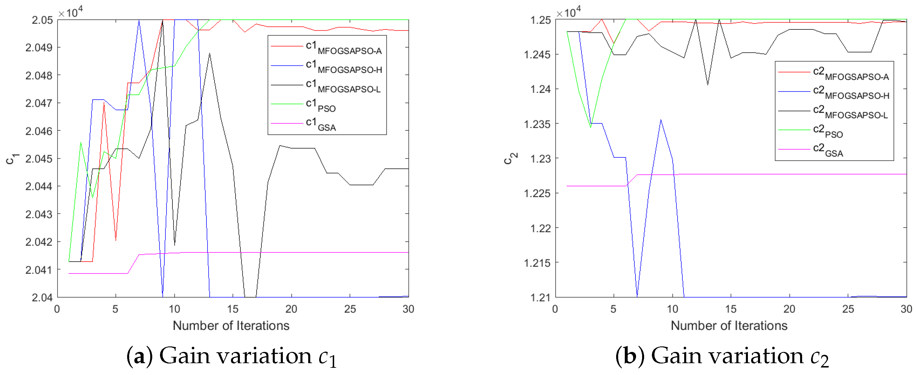
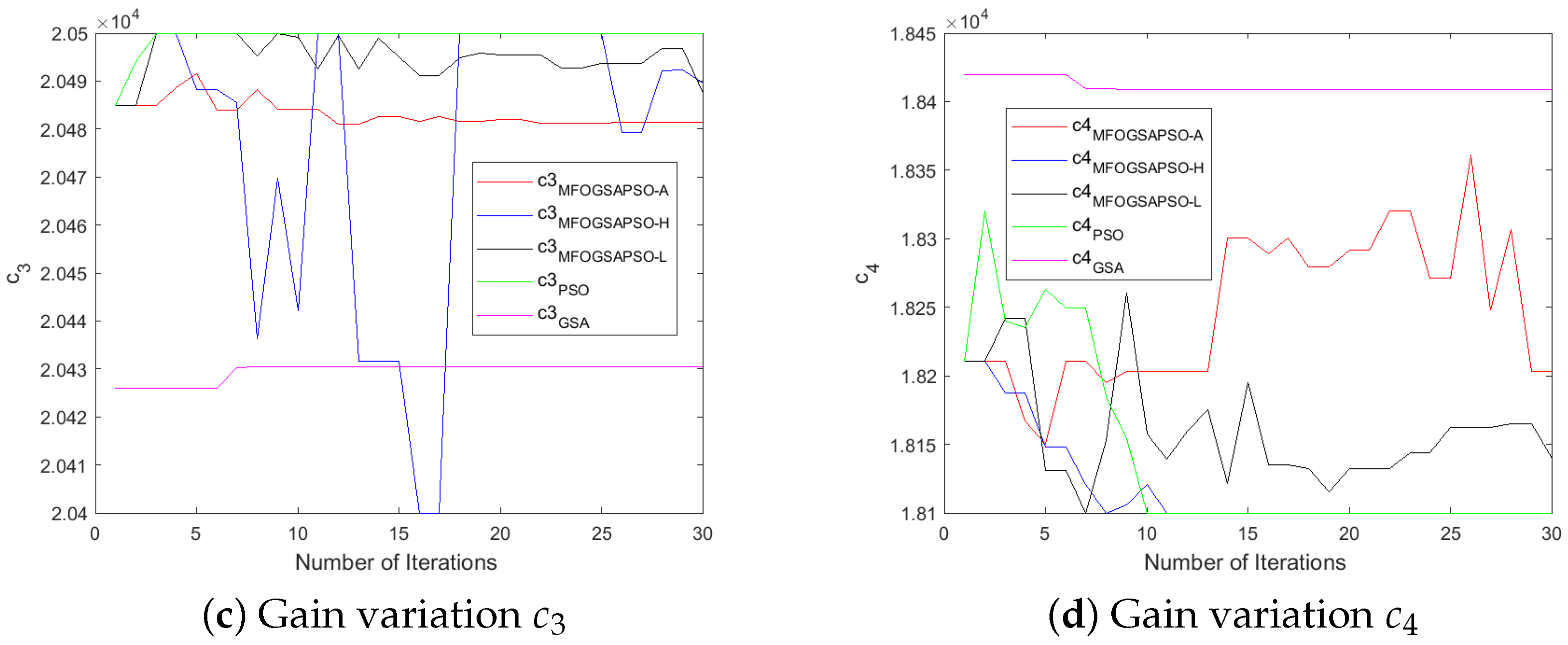
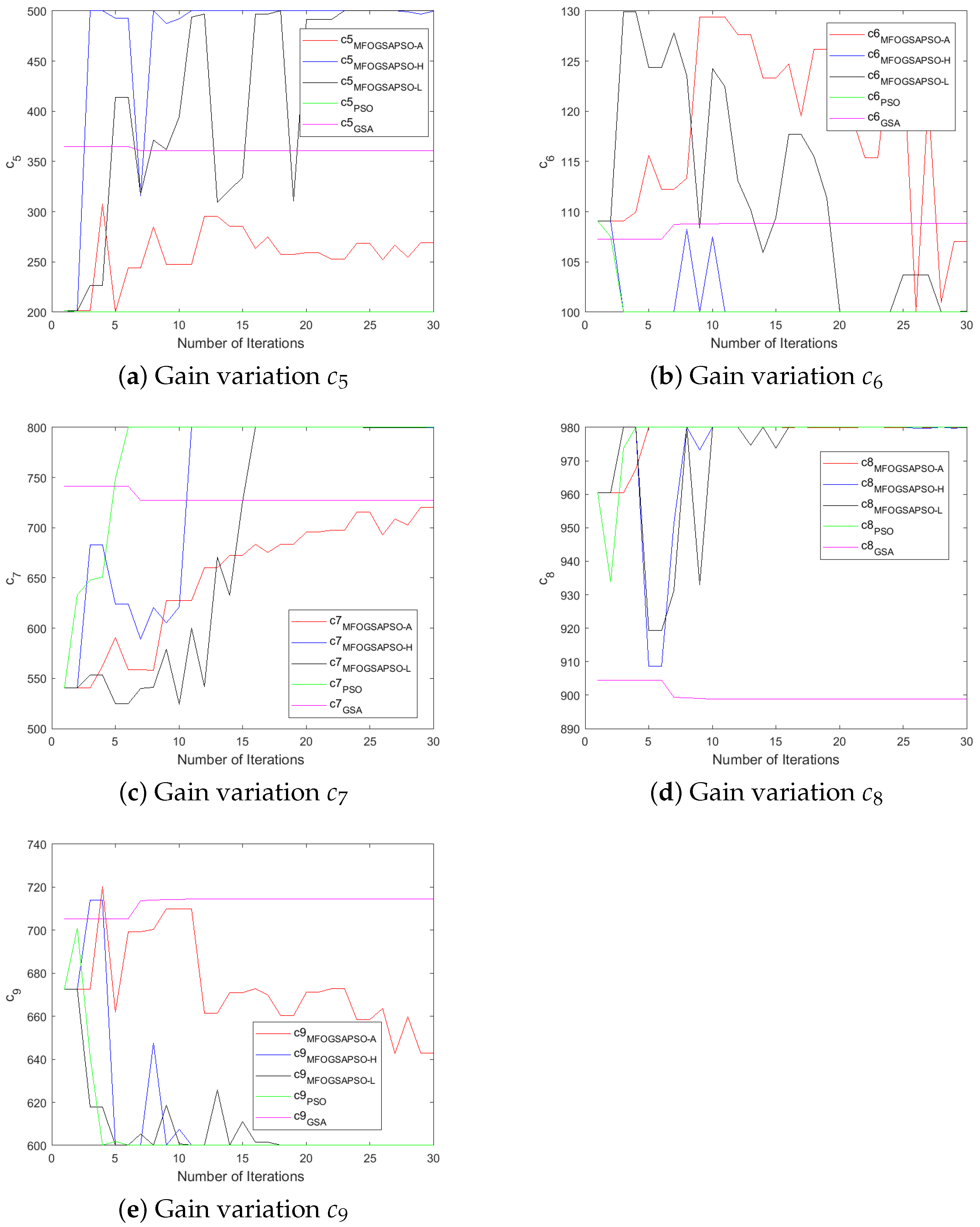
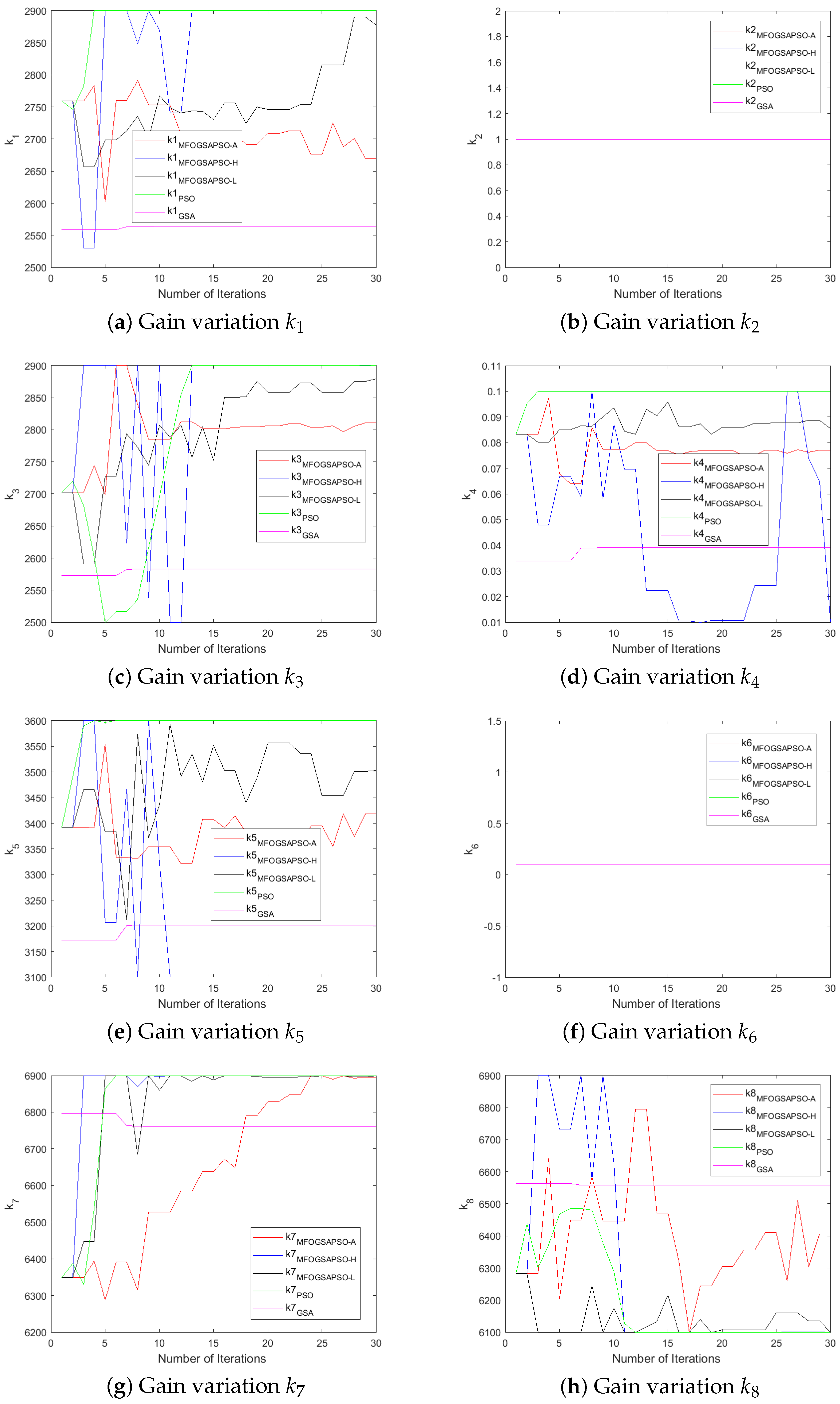
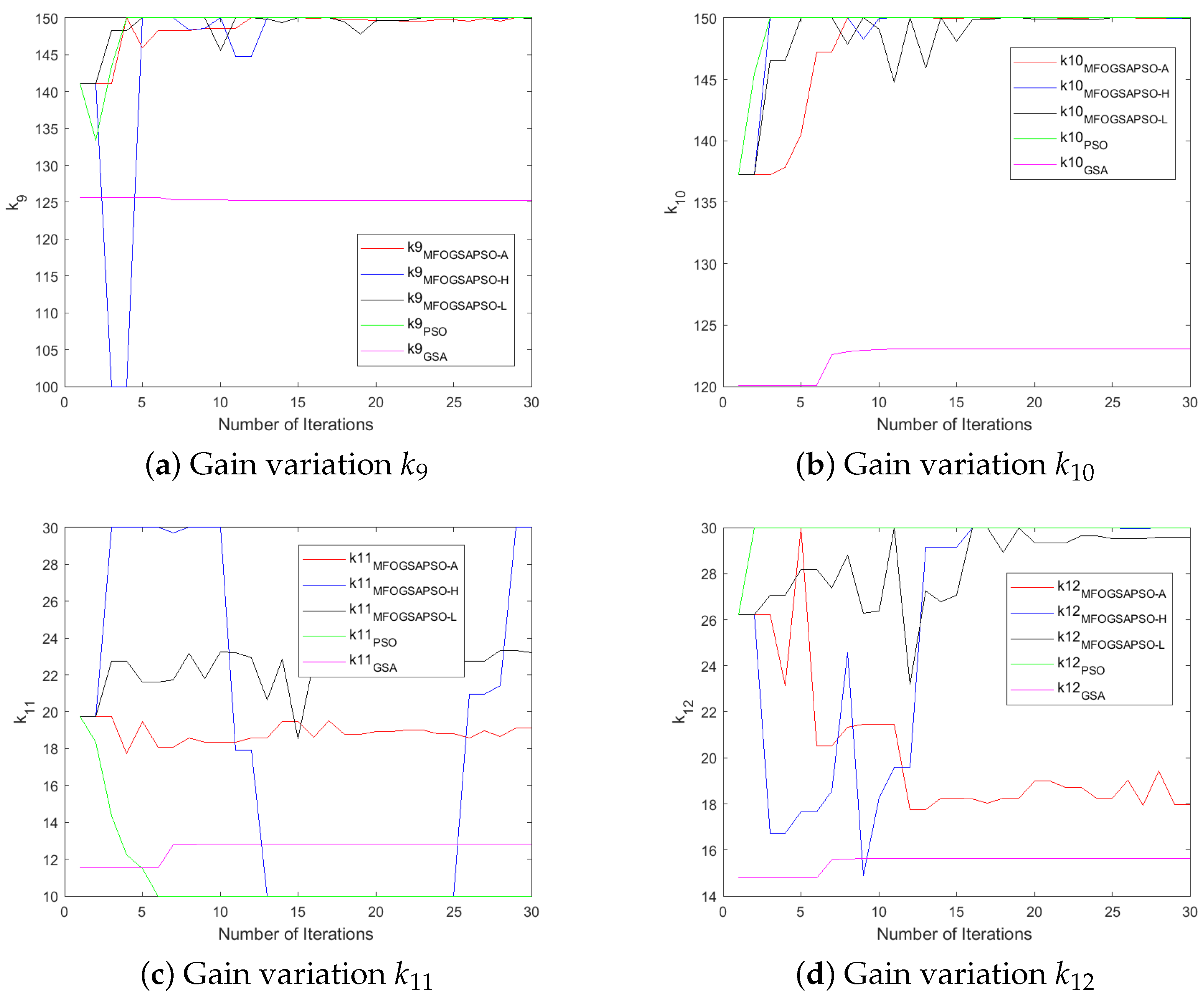
The controller-designed coefficients numerical values are depicted in Table A3. Initially, the values of parameters were chosen by the hit-and-trial method. After that, we utilized the three variants of moth flame optimization (as discussed in Section 5) to fine-tune the controller gains and improve the performance of the controller. The variants are MFOGSAPSO-L, MFOGSAPSO-A, and MFOGSAPSO-H. These variants are then compared with both GSA and PSO. A comparative analysis reveals close numerical proximity in key coefficients across the MFOGSAPSO variants, indicating stability and consistency in parameter tuning. Notably, coefficients such as , , and maintain high values across all MFOGSAPSO variants and the GSA, reflecting their dominant role in system dynamics.
The GSA exhibits slightly elevated values for (714), while showing lower gains for (3202) and (125), potentially suggesting a more conservative compensatory effort in control action. PSO, on the other hand, shows relatively high values for (3300), indicative of an assertive control mechanism potentially aimed at rapid system correction, although remains at 0 across all variants. The proportional coefficients and remain consistently high across the MFOGSAPSO variants, especially in MFOGSAPSO-H (2900 for both), indicating robust control sensitivity.
MFOGSAPSO-A demonstrates relatively balanced gains with lower , , and values (150, 19, and 18, respectively), implying smoother actuation and reduced control energy. PSO presents intermediate gain values in , , and (140, 20, and 22), situating its performance between the GSA and the smoother MFOGSAPSO approaches. Overall, the proposed MFOGSAPSO variants exhibit superior and well-distributed gain structures compared to both the GSA and PSO. While the GSA displays more aggressive gain patterns—likely influencing system responsiveness and energy consumption—PSO offers a balanced yet more assertive control strategy than MFOGSAPSO-A. The variations in controller gains during optimization are illustrated in Figure 6, Figure 7, Figure 8 and Figure 9.
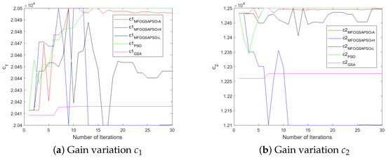
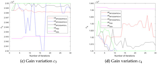
Figure 6.
Gain variations for HESS.
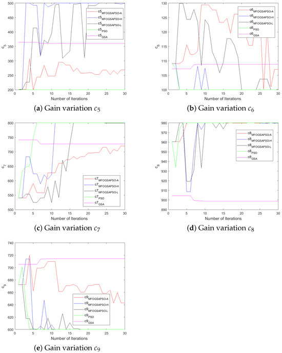
Figure 7.
Gain variations for motor.
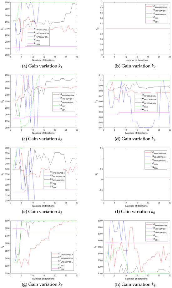
Figure 8.
Gain variations for HESS.
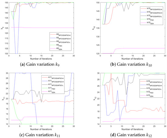
Figure 9.
Gain variations for motor.
7.5. Comparative Analysis of HESS Tracking and Speed Profile
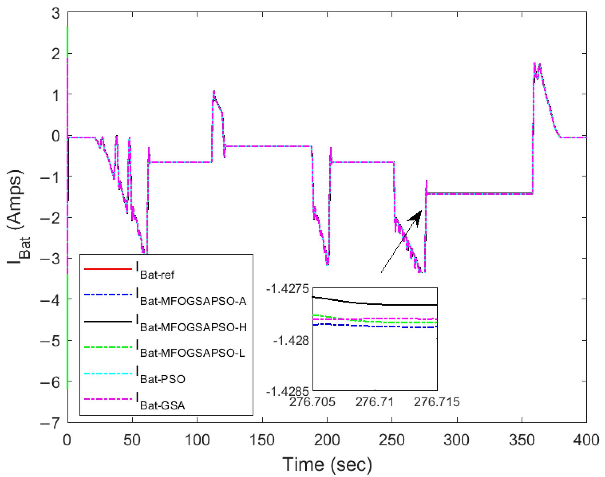
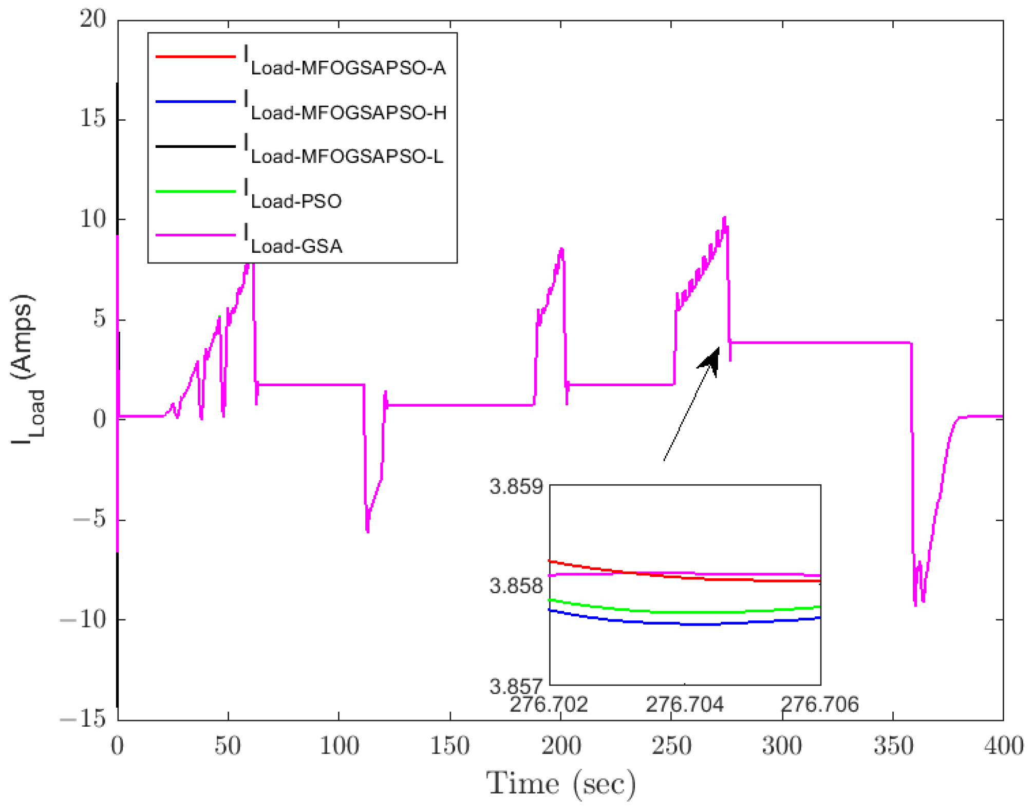
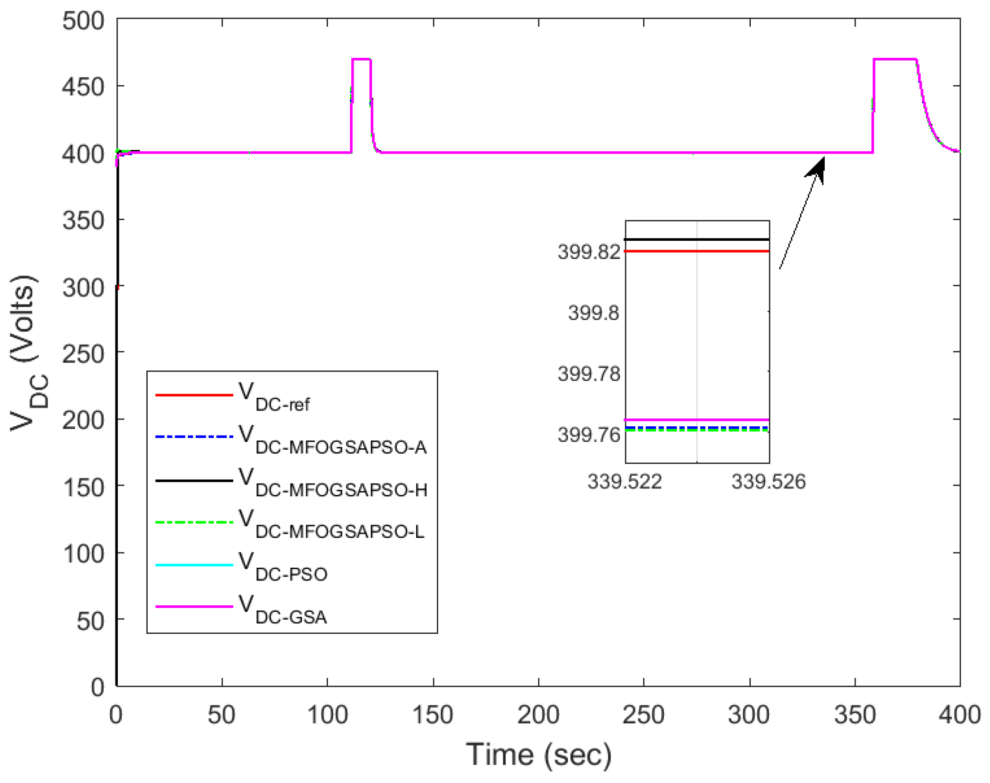
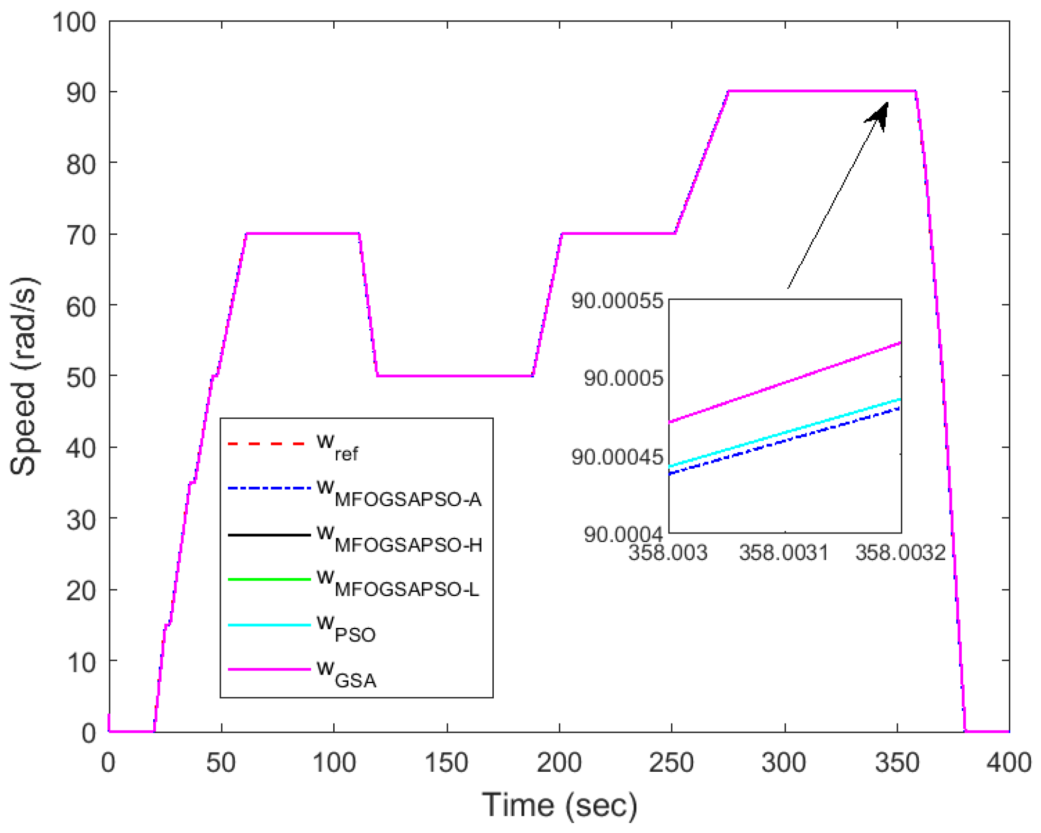
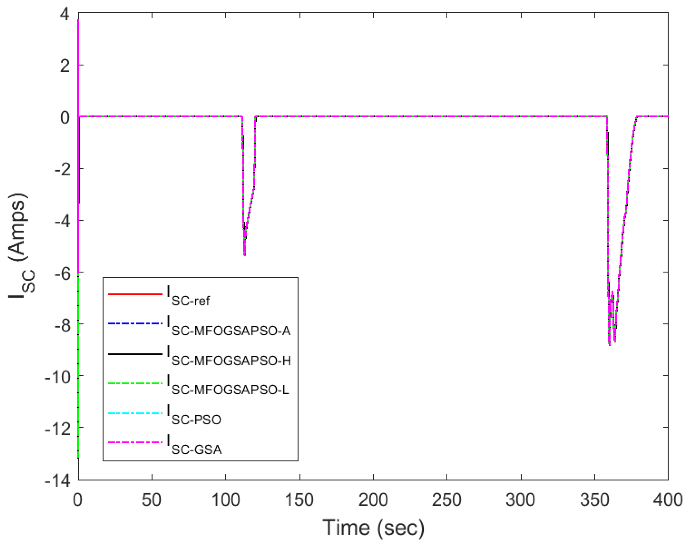
This section shows the comparison of tracking results for FC, battery, and SC currents along with DC bus voltage and vehicle speed tracking with respect to to their reference values. The dynamic responses of the system under different optimization methods are illustrated in Figure 10, Figure 11, Figure 12, Figure 13, Figure 14 and Figure 15. In battery current tracking (Figure 10), MFOGSAPSO-A demonstrates the lowest ripple and closest adherence to the reference trajectory, particularly during load changes. The magnified inset highlights its minimal overshoot and deviation compared to MFOGSAPSO-H, MFOGSAPSO-L, PSO, and GSA. MFOGSAPSO-H and MFOGSAPSO-L also exhibit competitive performance, whereas PSO and especially the GSA show delayed settling and higher fluctuation.
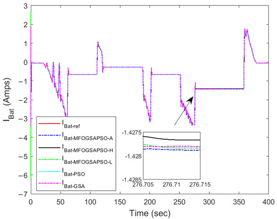
Figure 10.
Battery current tracking.
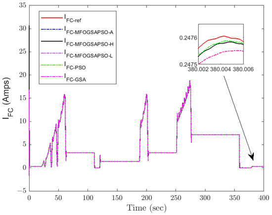
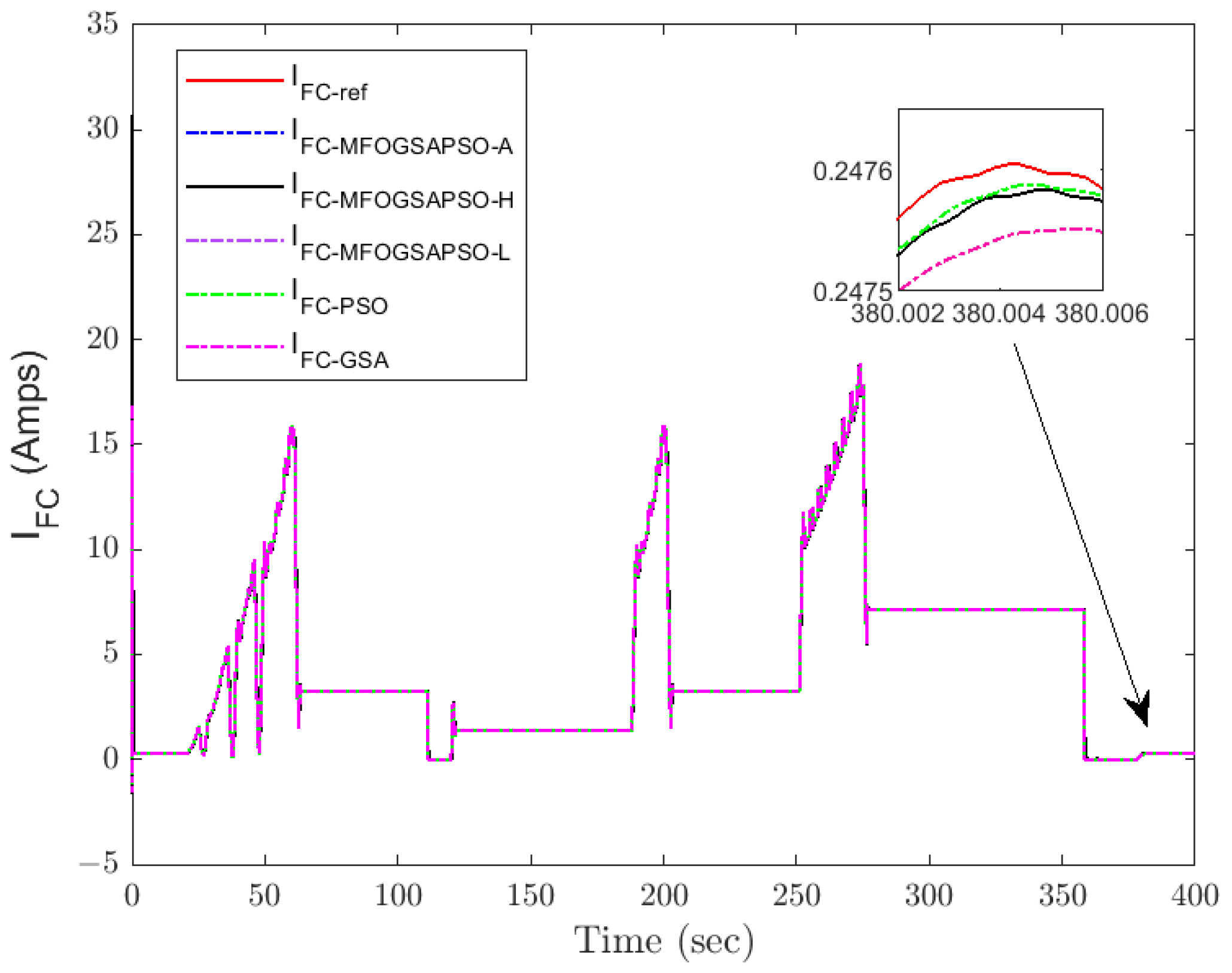
Figure 11.
Fuel cell current tracking.
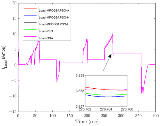
Figure 12.
Load current.
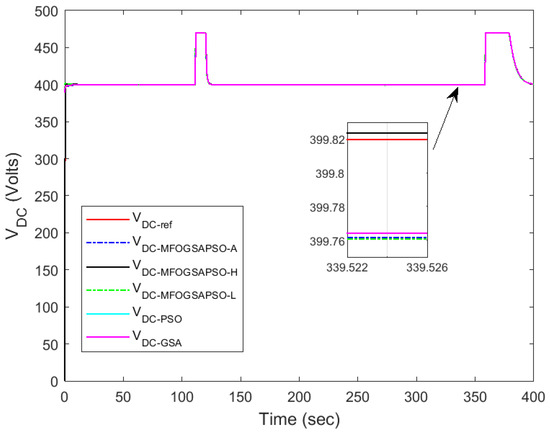
Figure 13.
DC bus voltage regulation performance.
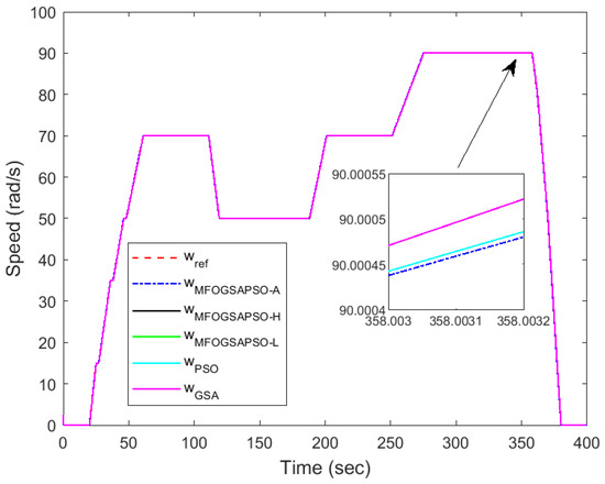
Figure 14.
Speed tracking.
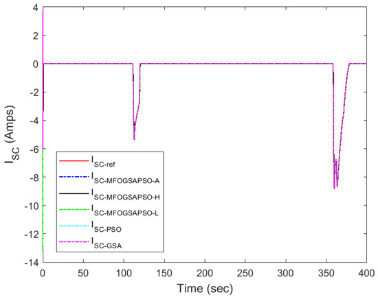
Figure 15.
Super-capacitor current tracking.
Fuel cell current tracking (Figure 11) confirms that MFOGSAPSO-L maintains superior performance with reduced overshoot and faster convergence near transient points, as highlighted in the zoomed view. In contrast, the GSA and PSO deviate more significantly from the reference during high-demand periods. Figure 12 shows load current behavior, where all methods closely follow each other, but MFOGSAPSO-H ensures the quickest damping after each load shift, indicating robust adaptability. Figure 13 illustrates DC bus voltage tracking, where MFOGSAPSO-A achieves the most stable and closest voltage response to the 400 V reference. The detailed inset confirms that both MFOGSAPSO-A and MFOGSAPSO-H outperform PSO and the GSA, which suffer from a larger ripple and slower stabilization.
Motor speed tracking is displayed in Figure 14, where MFOGSAPSO-A provides smoother and more accurate convergence to reference speeds during step changes. The zoom-in box highlights that the GSA and PSO have noticeable overshoot, while other methods remain tightly clustered below the reference. In super-capacitor current tracking, as depicted in Figure 15, the zoomed inset is not provided as the values are very small. MFOGSAPSO-A effectively tracks the reference with high fidelity, though MFOGSAPSO-L and MFOGSAPSO-H settle slightly faster post-transient than the GSA. Collectively, these plots reinforce that MFOGSAPSO-A provides the most consistent and precise control performance, especially in battery current, speed, and voltage regulation, while MFOGSAPSO-L excels in minimizing transient errors for fuel cell dynamics.
Among the three optimization techniques, MFOGSAPSO-A exhibits the most stable and accurate battery current tracking performance. While all controllers generally follow the desired battery current trajectory, the GSA and PSO experience relatively larger ripples and slightly delayed responses, which can potentially impact battery life in real-time systems. Therefore, MFOGSAPSO-A is the most effective technique in maintaining optimal charge/discharge control of the battery, minimizing stress on the energy storage system. The regulation of around the 400 V reference is essential for ensuring system voltage stability. MFOGSAPSO-A again demonstrates superior voltage control, exhibiting the smallest steady-state error and fastest recovery following transients.
8. Discussion
This work introduces a novel MFOGSAPSO-based optimization framework for dynamic sliding mode control (DSMC) in FCHEVs. The proposed framework combines (MFO) with fractional-order particle swarm optimization (PSO), the gravitational search algorithm (GSA), and fractal dynamics to enhance control performance under dynamic and uncertain environments. To the best of our knowledge, this hybrid structure along with its three spiral-inspired variants has not been previously applied to FCHEV control systems. To evaluate the effectiveness of the proposed methods, comprehensive simulations were conducted and compared against the GSA and PSO algorithms. The results clearly demonstrate that the proposed MFOGSAPSO-based framework significantly outperforms the conventional GSA and PSO approaches in terms of convergence speed, robustness, and control precision.
9. Conclusions
In this work, Lyapunov-based dynamic sliding mode control laws for the fuel cell, battery, super-capacitor, and motor subsystems, along with uniform robust exact differentiators, are designed for a fuel cell hybrid electric vehicle (FCHEV). The parameters used in the switching manifolds and control laws of the dynamic sliding mode control strategies are tuned using a fractal-swarming-based moth flame optimization (MFO) evolutionary computing paradigm. To address the complexity and high dimensionality of this nonlinear optimization task, traditional trial-and-error-based tuning methods are rendered ineffective. Three hybridized MFO variants—MFOGSAPSO-A, MFOGSAPSO-H, and MFOGSAPSO-L—were proposed and compared with the GSA and PSO. These variants integrate the base moth flame algorithm with gravitational search, particle swarm intelligence, and distinct functional enhancements. Among these, MFOGSAPSO consistently demonstrated superior steady-state tracking, smoother gain tuning, and minimum ITAE-based errors across multiple control objectives, establishing its effectiveness as the most reliable variant for FCHEV energy management.
Among these, MFOGSAPSO-A and MFOGSAPSO-L consistently demonstrated superior performance in both transient and steady-state conditions, achieving the lowest RMSE and MAE values across key control objectives such as FC, battery, SC current, DC bus voltage, and speed tracking. MFOGSAPSO-L, in particular, achieved the lowest ITAE values for fuel cell current (56.389865) and battery current (57.487649), indicating its strength in minimizing cumulative tracking error. Moreover, a comparative analysis against the conventional GSA and PSO algorithm revealed that the MFOGSAPSO-L variant significantly outperformed the GSA in terms of control accuracy, dynamic response, and overall system efficiency achieving up to 29% ITAE reduction in fuel cell current tracking and over 16% improvement in speed tracking. While PSO demonstrated moderately good performance, especially in DC bus voltage tracking, it still showed higher RMSE and MAE values than the MFOGSAPSO variants in most control objectives. This suggests that although PSO is competitive, it lacks the fine-tuned adaptability offered by the hybrid MFOGSAPSO approaches. The proposed control architecture is designed with real-time feasibility in mind, supporting seamless integration with platforms such as dSPACE or Opal RT. Given the computational complexity of the multi-objective optimization process, all parameter tuning is conducted offline to ensure no burden is placed on real-time execution. Future work will focus on implementing hardware-in-the-loop (HIL) validation to further confirm the real-world applicability and robustness of the proposed MFOGSAPSO-based DSMC framework for FCHEV energy management systems.
Author Contributions
Methodology, Writing original draft preparation, Implementation, N.Q.; Conceptualization and Supervision, L.K.; Software and Validation, M.W.; Formal analysis and Investigation, S.M.; Project Administration and Modeling, N.A.; Writing—review and editing, B.S.K. All authors have read and agreed to the published version of the manuscript.
Funding
This research received no external funding.
Data Availability Statement
The original contributions presented in this study are included in the article. Further inquiries can be directed to the corresponding author.
Conflicts of Interest
The authors declare no conflicts of interest.
Abbreviations
| EUDC | European Extra Urban Driving Cycle |
| FC | Fuel Cell |
| SC | Super-capacitor |
| DSMC | Dynamic Sliding Mode Control |
| MFO | Moth Flame Optimization |
| GSA | Gravitational Search Algorithm |
| PSO | Particle Swarm Optimization |
| AOA | Archimedes Optimization Algorithm |
| MFOGSAPSO | Moth Flame Optimization with GSA and PSO |
| MFOGSAPSO-A | MFOGSAPSO variant using archimedes sprial function |
| MFOGSAPSO-L | MFOGSAPSO variant using logarithmic spiral function |
| MFOGSAPSO-H | MFOGSAPSO variant using hyperbolic spiral function |
| WPT | Wireless Power Transfer |
| HESS | Hybrid Energy Storage System |
| SMC | Sliding Mode Control |
| ITAE | Integral of Time-weighted Absolute Error |
| EV | Electric Vehicle |
| Symbol | Description |
| DC link output voltage | |
| Fuel cell current | |
| Battery current | |
| Super-capacitor current | |
| Fuel cell output voltage | |
| Battery voltage | |
| , , | Switching control inputs |
| to | Error signals |
| to | HESS side state variables |
| to | Drive side state variables |
| , | Rotor flux components (d-q axis) |
| Rotor angular speed | |
| to | Sliding mode controller gains |
| to | Controller tuning coefficients |
| , | Resistance and inductance of FC |
| , | Resistance and inductance of battery |
| Output capacitance | |
| to | Sliding surfaces in DSMC |
| , | First- and second-time derivatives of variable x |
| ITAE | Integral of Time-weighted Absolute Error |
| RMSE | Root Mean Square Error |
| MAE | Mean Absolute Error |
Appendix A

Table A1.
Power sources and power stage.
Table A1.
Power sources and power stage.
| Component | Specifications |
|---|---|
| Power sources | |
| PEMFC | 350 V, 250 A, 34 kW |
| UC module | 205 V dc, 2700 F |
| Battery module | 288 V dc, 13.9 Ah, Li-ion |
| Power stage | |
| Inductance , , and | 3.3 mH |
| Inductance’s ESRs , , and | 20 mΩ |
| Output capacitor | 1.66 mF |
| Switching frequency | 20 kHz |

Table A2.
Electric traction motor.
Table A2.
Electric traction motor.
| Component | Specification |
|---|---|
| Motor type | 3-phase induction motor |
| Nominal power | 7.5 kW |
| Nominal voltage | 380 V |
| Nominal frequency | 50 Hz |
| Nominal flux | 1 Wb |
| Nominal power | 7.5 kW |
| 0.93 | |
| 1.633 | |
| 0.076 H | |
| 0.142 H | |
| 0.0018 | |
| 0.099 H | |
| p | 2 |
| J | 0.0111 |

Table A3.
Controller coefficients for optimized variants.
Table A3.
Controller coefficients for optimized variants.
| Coefficients to | ||||||||||||||
| (a) MFOGSAPSO-A | (b) MFOGSAPSO-H | (c) MFOGSAPSO-L | (d) PSO | (e) GSA | ||||||||||
| Coeff. | Values | Coeff. | Values | Coeff. | Values | Coeff. | Values | Coeff. | Values | |||||
| 20,496 | 20,400 | 20,446 | 20,310 | 20,416 | ||||||||||
| 12,497 | 12,100 | 12,496 | 12,345 | 12,277 | ||||||||||
| 20,481 | 20,490 | 20,487 | 20,320 | 20,430 | ||||||||||
| 18,203 | 18,100 | 18,410 | 18,050 | 18,409 | ||||||||||
| 269 | 500 | 500 | 400 | 361 | ||||||||||
| 107 | 100 | 100 | 105 | 109 | ||||||||||
| 720 | 800 | 800 | 710 | 727 | ||||||||||
| 980 | 980 | 980 | 970 | 899 | ||||||||||
| 643 | 600 | 600 | 630 | 714 | ||||||||||
| Coefficients to | ||||||||||||||
| (a) MFOGSAPSO-A | (b) MFOGSAPSO-H | (c) MFOGSAPSO-L | (d) PSO | (e) GSA | ||||||||||
| Coeff. | Values | Coeff. | Values | Coeff. | Values | Coeff. | Values | Coeff. | Values | |||||
| 2670 | 2900 | 2878 | 2630 | 2564 | ||||||||||
| 1 | 1 | 1 | 1 | 1 | ||||||||||
| 2811 | 2900 | 2880 | 2700 | 2583 | ||||||||||
| 0 | 0 | 0 | 0 | 0 | ||||||||||
| 3419 | 3100 | 3504 | 3300 | 3202 | ||||||||||
| 0 | 0 | 0 | 0 | 0 | ||||||||||
| 6895 | 6900 | 6900 | 6750 | 6760 | ||||||||||
| 6406 | 6100 | 6100 | 6300 | 6558 | ||||||||||
| 150 | 150 | 150 | 140 | 125 | ||||||||||
| 150 | 150 | 150 | 140 | 123 | ||||||||||
| 19 | 30 | 23 | 20 | 13 | ||||||||||
| 18 | 30 | 30 | 22 | 16 | ||||||||||

Table A4.
Performance indices for different optimization techniques for ( = 0.1).
Table A4.
Performance indices for different optimization techniques for ( = 0.1).
| Control Objective | Metric | MFOGSAPSO-A | MFOGSAPSO-H | MFOGSAPSO-L | PSO | GSA |
|---|---|---|---|---|---|---|
| FC Tracking | ITAE | 59.870123 | 60.678476 | 56.389856 | 61.235678 | 63.452341 |
| RMSE | 0.005712 | 0.005915 | 0.013826 | 0.006812 | 0.007543 | |
| MAE | 0.000602 | 0.000618 | 0.000604 | 0.000625 | 0.000650 | |
| Battery Tracking | ITAE | 58.112345 | 58.881124 | 57.487649 | 60.003489 | 65.273210 |
| RMSE | 0.004879 | 0.005015 | 0.009524 | 0.005823 | 0.006088 | |
| MAE | 0.000488 | 0.000499 | 0.000502 | 0.000523 | 0.000556 | |
| SC Tracking | ITAE | 63.145679 | 64.402142 | 62.836099 | 65.112234 | 68.878172 |
| RMSE | 0.002145 | 0.002232 | 0.003297 | 0.002355 | 0.002476 | |
| MAE | 0.000623 | 0.000647 | 0.000638 | 0.000660 | 0.000693 | |
| DC Bus Voltage Tracking | ITAE | 4739.812345 | 4744.595541 | 4741.607564 | 4770.451234 | 4839.196470 |
| RMSE | 0.232815 | 0.233030 | 0.233008 | 0.233456 | 0.234344 | |
| MAE | 0.058991 | 0.059033 | 0.059011 | 0.059600 | 0.060211 | |
| Speed Tracking | ITAE | 1052.112347 | 1056.605634 | 1100.365536 | 1175.111223 | 1276.189428 |
| RMSE | 0.030990 | 0.031326 | 0.032605 | 0.035734 | 0.037909 | |
| MAE | 0.010998 | 0.011201 | 0.011615 | 0.012477 | 0.013441 |

Table A5.
Performance indices for different optimization techniques for ( = 1).
Table A5.
Performance indices for different optimization techniques for ( = 1).
| Control Objective | Metric | MFOGSAPSO-A | MFOGSAPSO-H | MFOGSAPSO-L | PSO | GSA |
|---|---|---|---|---|---|---|
| FC Tracking | ITAE | 56.060205 | 55.864051 | 56.565690 | 61.235678 | 63.452341 |
| RMSE | 0.005180 | 0.013736 | 0.006369 | 0.006812 | 0.007543 | |
| MAE | 0.000569 | 0.000599 | 0.000580 | 0.000625 | 0.000650 | |
| Battery Tracking | ITAE | 66.626079 | 57.064064 | 57.060708 | 60.003489 | 65.273210 |
| RMSE | 0.005275 | 0.009471 | 0.005224 | 0.005823 | 0.006088 | |
| MAE | 0.000564 | 0.000499 | 0.000485 | 0.000523 | 0.000556 | |
| SC Tracking | ITAE | 65.934049 | 61.288168 | 62.372749 | 65.112234 | 68.878172 |
| RMSE | 0.002238 | 0.003240 | 0.002247 | 0.002355 | 0.002476 | |
| MAE | 0.000662 | 0.000622 | 0.000628 | 0.000660 | 0.000693 | |
| DC Bus Voltage Tracking | ITAE | 4741.355964 | 4740.926209 | 4741.850998 | 4770.451234 | 4839.196470 |
| RMSE | 0.232984 | 0.233003 | 0.232993 | 0.233456 | 0.234344 | |
| MAE | 0.058992 | 0.059002 | 0.059000 | 0.059600 | 0.060211 | |
| Speed Tracking | ITAE | 1084.606471 | 1100.910022 | 1098.115762 | 1175.111223 | 1276.189428 |
| RMSE | 0.032142 | 0.032620 | 0.032535 | 0.035734 | 0.037909 | |
| MAE | 0.011454 | 0.011620 | 0.011593 | 0.012477 | 0.013441 |

Table A6.
Comparison between fractional-order and integer-order MFOGSAPSO variants.
Table A6.
Comparison between fractional-order and integer-order MFOGSAPSO variants.
| Control Objective | Table A4 (Fractional-Order) | Table A5 (Integer-Order) | Insight |
|---|---|---|---|
| FC Tracking (ITAE) | Best: 56.389856 (MFOGSAPSO-L) | Best: 55.864051 (MFOGSAPSO-H) | Slightly better in integer-order. |
| Battery Tracking (ITAE) | Best: 57.487649 (MFOGSAPSO-L) | Best: 57.064064 (MFOGSAPSO-H) | Comparable performance. |
| SC Tracking (ITAE) | Best: 62.836099 (MFOGSAPSO-L) | Best: 61.288168 (MFOGSAPSO-H) | Integer-order slightly better. |
| DC Bus Voltage (ITAE) | Best: 4741.607564 (MFOGSAPSO-L) | Best: 4740.926209 (MFOGSAPSO-H) | Negligible difference. |
| Speed Tracking (ITAE) | Best: 1100.365536 (MFOGSAPSO-L) | Best: 1100.910022 (MFOGSAPSO-H) | Fractional-order slightly better. |
References
- Yao, E.; Liu, T.; Lu, T.; Yang, Y. Optimization of electric vehicle scheduling with multiple vehicle types in public transport. Sustain. Cities Soc. 2020, 52, 101862. [Google Scholar] [CrossRef]
- Hou, F.; Chen, X.; Chen, X.; Yang, F.; Ma, Z.; Zhang, S.; Liu, C.; Zhao, Y.; Guo, F. Comprehensive analysis method of determining global long-term GHG mitigation potential of passenger battery electric vehicles. J. Clean. Prod. 2020, 125137. [Google Scholar] [CrossRef]
- IEA. Tracking Transport 2020. Available online: https://www.iea.org/energy-system/transport/electric-vehicles (accessed on 12 September 2020).
- Xue, M.; Lin, B.-L.; Tsunemi, K. Emission implications of electric vehicles in Japan considering energy structure transition and penetration uncertainty. J. Clean. Prod. 2021, 280, 124402. [Google Scholar] [CrossRef]
- Rezaei, H.; Abdollahi, S.E.; Abdollahi, S.; Filizadeh, S. Energy management strategies of battery-ultracapacitor hybrid storage systems for electric vehicles: Review, challenges, and future trends. J. Energy Storage 2022, 53, 105045. [Google Scholar] [CrossRef]
- Wang, Y.; Wang, L.; Li, M.; Chen, Z. A review of key issues for control and management in battery and ultra-capacitor hybrid energy storage systems. eTransportation 2020, 4, 100064. [Google Scholar] [CrossRef]
- Panaparambil, S.; Kashyap, Y.; Castelino, R.V. A review on hybrid source energy management strategies for electric vehicle. Int. J. Energy Res. 2021, 45, 19819–19850. [Google Scholar] [CrossRef]
- AlKawak, O.A.; Kumar, J.R.R.; Daniel, S.S.; Reddy, C.V.K. Hybrid method based energy management of electric vehicles using battery super capacitor energy storage. J. Energy Storage 2024, 77, 109835. [Google Scholar] [CrossRef]
- Sankarkumar, R.S.; Natarajan, R. Energy management techniques and topologies suitable for hybrid energy storage system powered electric vehicles: An overview. Int. Trans. Electr. Energy Syst. 2021, 31, e12819. [Google Scholar] [CrossRef]
- Liu, Y.; Zhang, Y.; Yu, H.; Nie, Z.; Liu, Y.; Chen, Z. A novel data-driven controller for plug-in hybrid electric vehicles with improved adaptabilities to driving environment. J. Clean. Prod. 2022, 334, 130250. [Google Scholar] [CrossRef]
- Ramos, G.A.; Costa-Castelló, R. Energy management strategies for hybrid energy storage systems based on filter control: Analysis and comparison. Electronics 2022, 11, 1631. [Google Scholar] [CrossRef]
- Marulasiddappa, H.B.; Pushparajesh, V. Review on different control techniques for induction motor drive in electric vehicle. IOP Conf. Ser. Mater. Sci. Eng. 2021, 1055, 012142. [Google Scholar] [CrossRef]
- Bhat, V.S.; Kumar, V.; Dayanand, N.; Shettigar, A.; Nikhitha. Comparative study of PID control algorithms for an electric vehicle. In Proceedings of the AIP Conference Proceedings, Jaipur, India, 5–6 March 2020; American Institute of Physics Inc.: College Park, MD, USA, 2020; Volume 2236, p. 080001. [Google Scholar]
- Munir, M.F.; Ahmad, I.; Siffat, S.A.; Qureshi, M.A.; Armghan, H.; Ali, N. Non-linear control for electric power stage of fuel cell vehicles. ISA Trans. 2020, 102, 117–134. [Google Scholar] [CrossRef]
- Ji, X.; Ding, S.; Cui, B.; Ding, C.; Wei, X. Barrier function-based nonsingular terminal sliding mode control for path tracking of tractor-like with experimental validation. IEEE Trans. Circuits Syst. II Exp. Briefs 2023, 70, 3024–3028. [Google Scholar] [CrossRef]
- Hwang, H.-Y.; Chen, J.-S. Optimized fuel economy control of power-split hybrid electric vehicle with particle swarm optimization. Energies 2020, 13, 2278. [Google Scholar] [CrossRef]
- Lü, X.; Wu, Y.; Lian, J.; Zhang, Y.; Chen, C.; Wang, P.; Meng, L. Energy management of hybrid electric vehicles: A review of energy optimization of fuel cell hybrid power system based on genetic algorithm. Energy Convers. Manag. 2020, 205, 112474. [Google Scholar] [CrossRef]
- Rashedi, E.; Nezamabadi-Pour, H.; Saryazdi, S. GSA: A gravitational search algorithm. Inf. Sci. 2009, 179, 2232–2248. [Google Scholar] [CrossRef]
- Arora, S.; Singh, S. Butterfly algorithm with Levy flights for global optimization. In Proceedings of the 2015 International Conference on Signal Processing, Computing and Control (ISPCC), Solan, India, 24–26 September 2015; pp. 220–224. [Google Scholar]
- Khan, B.S.; Raja, M.A.Z.; Qamar, A.; Chaudhary, N.I. Design of moth flame optimization heuristics for integrated power plant system containing stochastic wind. Appl. Soft Comput. 2021, 104, 107193. [Google Scholar] [CrossRef]
- Mirjalili, S.; Lewis, A. The whale optimization algorithm. Adv. Eng. Softw. 2016, 95, 51–67. [Google Scholar] [CrossRef]
- Mirjalili, S.; Gandomi, A.H.; Mirjalili, S.Z.; Saremi, S.; Faris, H.; Mirjalili, S.M. Salp swarm algorithm: A bio-inspired optimizer for engineering design problems. Adv. Eng. Softw. 2017, 114, 163–191. [Google Scholar] [CrossRef]
- Qais, M.H.; Hasanien, H.M.; Alghuwainem, S. Enhanced whale optimization algorithm for maximum power point tracking of variable-speed wind generators. Appl. Soft Comput. 2020, 86, 105937. [Google Scholar] [CrossRef]
- Wei, Z.; He, Z.; Yang, F.; Sun, B. A method for optimizing terminal sliding mode controller parameters based on a multi-strategy improved crayfish algorithm. Appl. Sci. 2024, 14, 8085. [Google Scholar] [CrossRef]
- Zhou, Z.; Wang, C.; Zhu, Z.; Wang, Y.; Yang, D. Sliding mode control based on a hybrid grey-wolf-optimized extreme learning machine for robot manipulators. Optik 2019, 185, 364–380. [Google Scholar] [CrossRef]
- Roy, R.G.; Ghoshal, D. Grey wolf optimization-based second order sliding mode control for inchworm robot. Robotica 2020, 38, 1539–1557. [Google Scholar] [CrossRef]
- Rahmani, M.; Komijani, H.; Rahman, M.H. New sliding mode control of 2-DOF robot manipulator based on extended grey wolf optimizer. Int. J. Control Autom. Syst. 2020, 18, 1572–1580. [Google Scholar] [CrossRef]
- Ullah, S.; Hayat, R.; Zeb, K.; Rasheed, A.; Muyeen, S.M. Super twisting sliding mode controller for energy storage system of a novel multisource hybrid electric vehicle: Simulation and hardware validation. Int. J. Hydrogen Energy 2024, 71, 952–963. [Google Scholar] [CrossRef]
- Korada, S.R.; Brinda, R.; Soubache, I.D. Energy management strategy for photovoltaic powered hybrid energy storage systems in electric vehicles. Int. J. Electr. Comput. Eng. 2024, 14, 1228. [Google Scholar]
- Zhang, L.; Wang, Y.; Wang, Z. Robust Lateral Motion Control for In-Wheel-Motor-Drive Electric Vehicles with Network Induced Delays. IEEE Trans. Veh. Technol. 2019, 68, 10585–10593. [Google Scholar] [CrossRef]
- Lu, Z.; Shieh, L.S.; Chen, G.; Coleman, N.P. Simplex Sliding Mode Control for Nonlinear Uncertain Systems via Chaos Optimization. Chaos Solitons Fractals 2005, 23, 747–755. [Google Scholar] [CrossRef]
- Thanok, S.; Parnichkun, M. Longitudinal Control of an Intelligent Vehicle Using Particle Swarm Optimization Based Sliding Mode Control. Adv. Robot. 2015, 29, 525–543. [Google Scholar] [CrossRef]
- Serbencu, A.E.; Serbencu, A.; Cernega, D.C.; Minzu, V. Particle Swarm Optimization for the Sliding Mode Controller Parameters. In Proceedings of the 29th Chinese Control Conference (CCC), Beijing, China, 29–31 July 2010; pp. 1859–1864. [Google Scholar]
- Anand, R.; Mary, P.M. Improved Dynamic Response of DC to DC Converter Using Hybrid PSO Tuned Fuzzy SMC. Circuits Syst. 2016, 7, 946–955. [Google Scholar] [CrossRef]
- Soriano, L.A.; Rubio, J.J.; Orozco, E.; Cordova, D.A.; Ochoa, G.; Balcazar, R.; Cruz, D.R.; Meda-Campaña, J.A.; Zacarias, A.; Gutierrez, G.J. Optimization of Sliding Mode Control to Save Energy in a SCARA Robot. Mathematics 2021, 9, 3160. [Google Scholar] [CrossRef]
- Zhou, C.; Liu, X.; Chen, W.; Xu, F.; Cao, B. Optimal Sliding Mode Control for an Active Suspension System Based on a Genetic Algorithm. Algorithms 2018, 11, 205. [Google Scholar] [CrossRef]
- Hasan, M.K.; Mahmud, M.; Habib, A.A.; Motakabber, S.; Islam, S. Review of Electric Vehicle Energy Storage and Management System: Standards, Issues, and Challenges. J. Energy Storage 2021, 41, 102940. [Google Scholar] [CrossRef]
- Ali, N.; Liu, Z.; Armghan, H.; Armghan, A. Super-Twisting Sliding Mode Controller for Maximum Power Transfer Efficiency Tracking in Hybrid Energy Storage-Based Wireless In-Wheel Motor. Sustain. Energy Technol. Assess. 2022, 52, 102075. [Google Scholar] [CrossRef]
- Alsharif, A.; Tan, C.W.; Ayop, R.; Dobi, A.; Lau, K.Y. A Comprehensive Review of Energy Management Strategy in Vehicle-to-Grid Technology Integrated with Renewable Energy Sources. Sustain. Energy Technol. Assess. 2021, 47, 101439. [Google Scholar] [CrossRef]
- Gao, D.; Luo, Z.; Liu, C.; Fan, S. A Survey of Hybrid Energy Devices Based on Supercapacitors. Green Energy Environ. 2023, 8, 972–988. [Google Scholar] [CrossRef]
- Herrera, M.; Camacho, O.; Leiva, H.; Smith, C. An Approach of Dynamic Sliding Mode Control for Chemical Processes. J. Process Control 2020, 85, 112–120. [Google Scholar] [CrossRef]
- Ramirez, B. Strategies for Optimizing Energy Use in EVs. J. Power Sources 2020, 16, 68–75. [Google Scholar]
- Brooks, W. Optimizing Electric Vehicle Performance. IEEE Trans. Transp. Electrif. 2021, 6, 160–167. [Google Scholar]
- Mirjalili, S. Moth-Flame Optimization Algorithm: A Novel Nature-Inspired Heuristic Paradigm. Knowl.-Based Syst. 2015, 89, 228–249. [Google Scholar] [CrossRef]
- Kigsirisin, S.; Miyauchi, H. Short-Term Operational Scheduling of Unit Commitment Using Binary Alternative Moth-Flame Optimization. IEEE Access 2021, 9, 12267–12281. [Google Scholar] [CrossRef]
- Khan, B.S.; Qamar, A.; Ullah, F.; Bilal, M. Ingenuity of Shannon Entropy-Based Fractional Order Hybrid Swarming Strategy to Solve Optimal Power Flows. Chaos Solitons Fractals 2023, 170, 113312. [Google Scholar] [CrossRef]
Disclaimer/Publisher’s Note: The statements, opinions and data contained in all publications are solely those of the individual author(s) and contributor(s) and not of MDPI and/or the editor(s). MDPI and/or the editor(s) disclaim responsibility for any injury to people or property resulting from any ideas, methods, instructions or products referred to in the content. |
© 2025 by the authors. Published by MDPI on behalf of the World Electric Vehicle Association. Licensee MDPI, Basel, Switzerland. This article is an open access article distributed under the terms and conditions of the Creative Commons Attribution (CC BY) license (https://creativecommons.org/licenses/by/4.0/).

