1. Introduction
Control moment gyroscopes (CMGs) are essential for spacecraft attitude control, generating substantial torque within a compact design [
1]. This attribute renders them critical for precise spacecraft orientation. CMGs function by leveraging the angular momentum of a high-speed rotor, which is transformed into torque for spacecraft maneuvering [
2]. Typically, CMGs comprise a rotor assembly within an external frame, supported by gimbals to enable gyroscopic torque control [
3]. A critical research gap lies in developing cost-effective motor designs that achieve high torque density and minimal torque pulsation for low-speed CMG applications.
The effectiveness of CMGs relies heavily on the external frame motor, which must meet stringent requirements, including high torque density, low cogging torque, and optimal efficiency at low speeds [
4]. These qualities are vital for ensuring the stability and precision required in spacecraft applications. Hence, optimizing the motor’s magnetic structure is crucial for enhancing CMG performance [
5]. This study explores the design and analysis of low-speed external frame motors that incorporate advanced magnet configurations. Previous research has predominantly utilized Halbach-type magnets to improve torque density and reduce pulsation, achieving torque pulsation values of 1.2–1.8 mN·m in similar low-speed applications, demonstrating their efficacy in high-torque scenarios. However, these designs often entail compromises in manufacturability and cost, posing significant challenges for CMGs where performance must align with budget constraints. In contrast, this study’s olive-shaped magnet structure yields a torque pulsation of 0.9 mN·m, outperforming previously studied conventional designs (1.5–2.0 mN·m) and Halbach-type motors.
External rotor permanent magnet torque motors have attracted significant interest due to their high torque density, compact design, and exceptional efficiency, making them ideal for applications such as electric vehicles and mobile robotics [
6]. Extensive research has examined their operational principles, electromagnetic performance, and optimization strategies [
7]. A central focus of their design is the rotor’s magnetic structure. Novel configurations, such as Halbach-type and olive-shaped magnet structures, have been explored to enhance performance [
8,
9]. The Halbach-type configuration, characterized by a specific magnet orientation, amplifies the magnetic field on one side while suppressing it on the other, yielding increased torque density and reduced cogging torque [
10]. Studies demonstrate that Halbach-type magnets, including segmented arrays, offer improved torque characteristics, lower torque ripple, and superior magnetic field control, fostering operational stability and efficiency in high-torque, low-speed applications. This is evidenced by advancements in passive magnetorheological brake systems and permanent magnet Vernier motors [
11,
12] and reinforced by targeted studies on optimized Halbach array designs [
13,
14].
Despite these benefits, Halbach-type configurations encounter challenges in manufacturing complexity and cost. To address these drawbacks, the olive-shaped magnet structure has been proposed as an effective alternative [
15]. This design has a streamlined magnet arrangement while preserving robust electromagnetic performance [
16,
17]. Finite element analysis (FEA) confirms that olive-shaped magnet motors achieve high torque density and efficiency, making them well-suited for applications where cost and manufacturability are paramount [
7,
18]. This study tackles the challenge of optimizing motor designs for low-speed CMGs to balance performance and manufacturability, proposing olive-shaped magnet structures for enhanced torque stability and cost-effectiveness.
In the realm of CMGs, which are indispensable for spacecraft attitude control due to their remarkable moment amplification capabilities, the precision and stability of low-speed frame systems are critical [
19,
20,
21]. The external frame torque motor, a fundamental component of the CMG’s drive system, benefits from innovations that minimize cogging torque and boost torque density [
22]. Implementing external rotor structures with optimized magnet configurations, such as Halbach-type or olive-shaped magnets, coupled with centralized fractional-slot winding techniques, effectively mitigates cogging torque and enhances motor performance [
22]. This study builds upon prior research by rigorously demonstrating that the olive-shaped magnet structure provides an optimal balance of performance and manufacturability for CMG applications, delivering comparable or superior torque stability (reduced pulsation) relative to complex Halbach designs while offering a more streamlined, cost-effective manufacturing strategy.
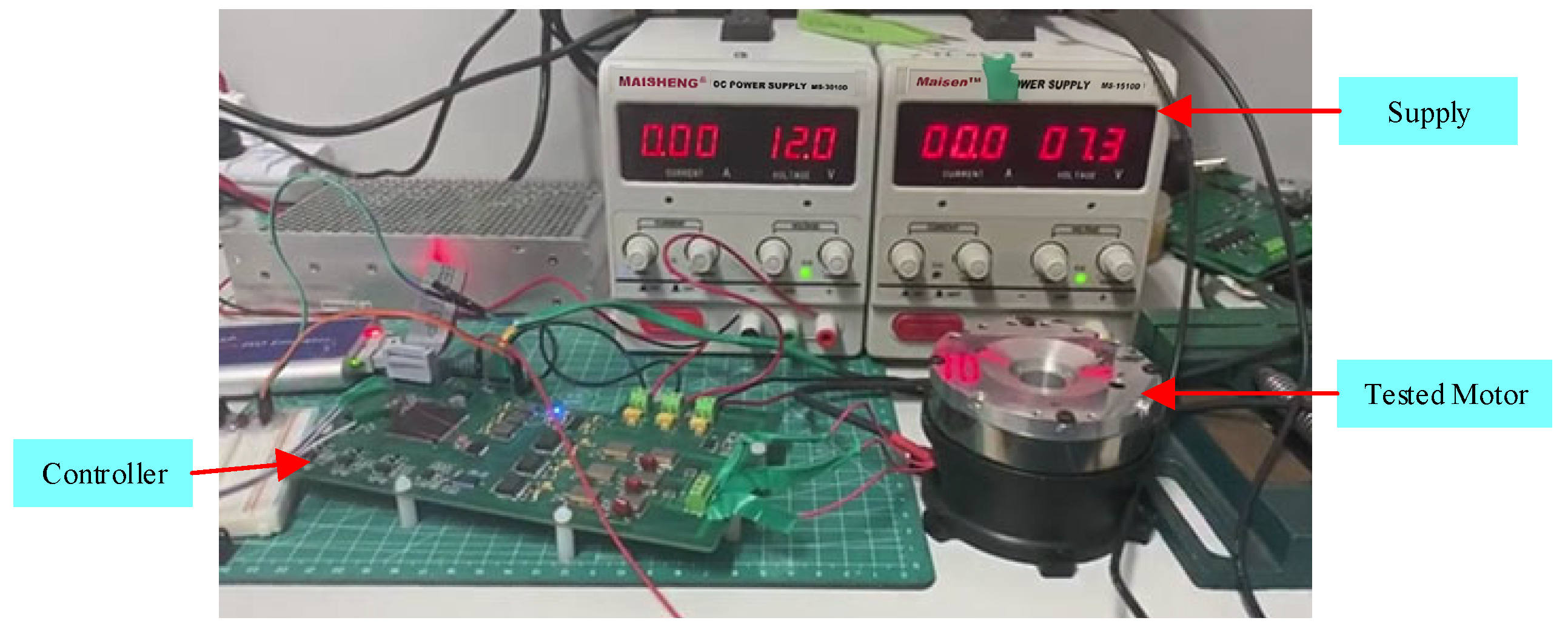
This paper presents a comprehensive analysis of low-speed external frame motors, focusing on the comparative performance of Halbach-type and olive-shaped magnet structures for CMG applications. The study optimizes rotor pole configurations to enhance electromagnetic performance, employing finite element analysis to assess magnetic field distribution, cogging torque, and torque pulsation under diverse operating conditions. Experimental validation through a custom-designed motor and control system verifies low-speed precision and stability, establishing the olive-shaped magnet structure as a premier, cost-effective solution for aerospace motor technology.
2. Motor Modeling
2.1. Design Requirements
The design and analysis of low-speed external frame motors with Halbach-type and olive-shaped magnet structures aim to maximize efficiency, reduce size, and improve torque stability for control moment gyroscope (CMG) applications in spacecraft. The Halbach-type configuration, pioneered by K. Halbach in 1979, arranges permanent magnets to create a sinusoidal magnetic field, making it highly suitable for external rotor permanent magnet synchronous motors (PMSMs). The olive-shaped magnet structure is adopted for its capacity to meet dimensional constraints, minimize torque pulsation, and deliver efficient low-speed performance under load [
22]. Comprehensive motor design specifications, as listed in
Table 1, include dimensions, torque, electrical properties, and operational limits to ensure optimal performance in aerospace CMG systems. This design emphasizes thermal management, electromagnetic interference (EMI) suppression, and torque smoothness. The olive-shaped magnet structure significantly enhances performance by reducing cogging torque, improving load-handling capability, and increasing system efficiency.
The motor’s continuous stall torque of 0.2 N·m and peak power loss of 20 W limit its suitability for heavy loads or prolonged operation. With a resistance of 1.8 ± 0.2 Ω and inductance ≤5 mH, it may exhibit delayed transient responses and increased power losses, rendering it ideal for light-duty, precision-control tasks in CMGs.
2.2. Modeling of Halbach-Type and Olive-Shaped Magnet Motors
The low-speed external frame motor incorporates an 18-slot stator and a 20-pole rotor with a centralized fractional-slot winding configuration, as illustrated in
Figure 1. This design minimizes winding end-turn length, thereby reducing the motor’s volume and weight. The Halbach-type magnetic structure consists of three permanent magnet blocks per pole, a central block with radial magnetization and two adjacent blocks magnetized at a 10° angle, as depicted in
Figure 1. This arrangement generates a sinusoidal magnetic field, enhancing motor efficiency by integrating radial and tangential magnetization components. The Halbach configuration optimizes air-gap flux density, increasing torque density and minimizing cogging torque. The fractional-slot winding promotes smoother load handling, significantly improving performance in low-speed, precision-driven applications such as CMGs.
Figure 2 presents a schematic of the permanent magnet array. The Halbach-type magnetization directs magnetic flux to one side of the rotor, enhancing torque output while reducing motor size and weight. This optimized electromagnetic configuration strengthens stator–rotor interactions, enabling a compact design with high torque density and lower energy losses, making it highly suitable for low-speed applications where efficiency and compactness are paramount.
The rotor also features an olive-shaped magnet structure, as shown in
Figure 3, with each pole comprising a single radially magnetized olive-shaped permanent magnet. This novel design optimizes air-gap magnetic field distribution, substantially reducing harmonic content, cogging torque, and harmonic-induced torque pulsation. As a result, the motor delivers smoother operation with minimal torque pulsation, significantly enhancing overall performance.
The olive-shaped magnet configuration effectively mitigates higher-order harmonics by suppressing undesirable harmonic amplitudes, ensuring that most harmonics are even-order. This way, they can be more easily eliminated, thereby reducing noise and vibration. The air-gap magnetic field arises from the combined effects of the stator armature reaction and the rotor’s permanent magnet magnetic potential, modulated by air-gap permeability. Harmonic analysis indicates that stator slotting influences the magnetic field’s spatial distribution but not its frequency. The electromagnetic force harmonics, primarily even-order, align with the greatest common divisor of the pole and slot numbers, simplifying their suppression. The 18-slot, 20-pole configuration, combined with Halbach-type and olive-shaped magnet structures, greatly enhances magnetic field distribution and harmonic suppression, producing a motor optimized for low-speed and high-torque applications with superior efficiency, stability, and minimal mechanical vibrations.
2.3. Mathematical Model of Halbach Magnet Orientation Distribution
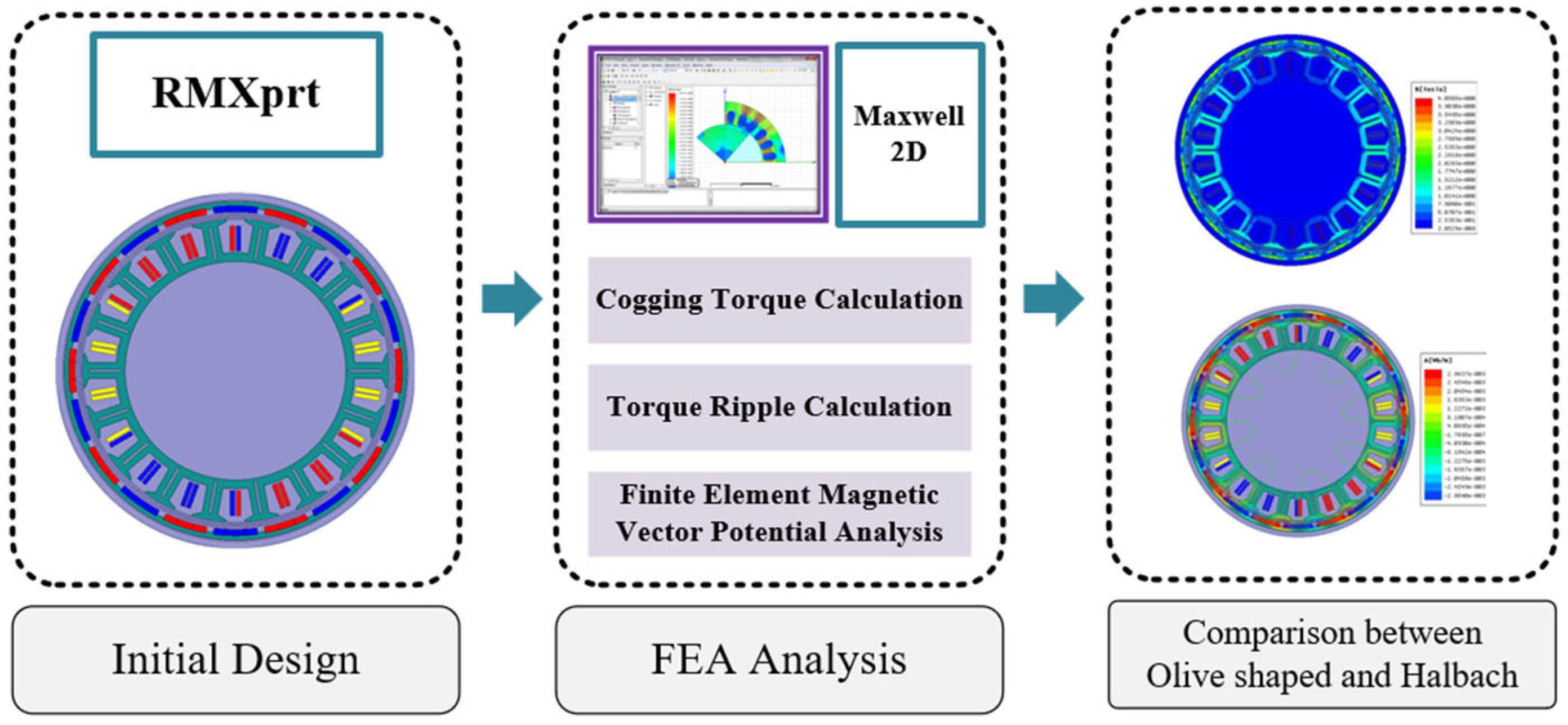
This study employed an integrated analytical–computational methodology for designing and evaluating low-speed external frame motors with Halbach-type and olive-shaped magnet topologies (
Figure 4). The framework systematically combines the initial geometry (18-slot stator, 20-pole rotor) and magnetization profiles derived from torque-speed requirements. Halbach arrays follow
where
M0 is the magnetization amplitude,
θ is the angular position, and
er and
eθ are radial and tangential unit vectors.
While olive-shaped magnets incorporate geometry-optimized phase modulation
where
φ(
θ) is a phase-shift function optimized via parameter sweeps to minimize harmonic distortions.
High-fidelity magnetostatic FEA (COMSOL) solves the following
where
μ0 is the permeability of free space,
A is the magnetic vector potential, and
M is the magnetization vector. Boundary conditions include ∇ ×
A = 0 at air-gap interfaces and
M(
θ) on rotor surfaces. Mesh convergence is achieved with residuals below 10
−5, using 0.05 mm elements in the air gap, 0.1 mm in teeth/slots, and 0.5 mm in back iron, ensuring numerical accuracy.
Torque ripple, a critical metric, is found in the following:
where
Tmax,
Tmin, and
Tavg are the maximum, minimum, and average torque values, respectively.
Cogging torque is quantified as
and field uniformity is evaluated across operational regimes (no-load/maximum torque/linked-shaft).
Above, Φ is the magnetic flux and ∂Φ/∂θ represents the flux variation with respect to angular position. Field uniformity is assessed to ensure stable operation. Both topologies are benchmarked under identical electromagnetic loading, with sensitivity analyses (offset angles: 0–15°; phase-shift functions) quantifying harmonic cancelation efficacy against industrial thresholds: torque ripple ∆
T < 1% and cogging torque
Tc < 3 mN·m.
This schematic outlines an electromagnetic design workflow utilizing RMXprt for initial motor design, incorporating Maxwell 2D simulations for cogging torque, torque ripple, and magnetic vector potential analysis. Subsequent finite element analysis (FEA) comparatively evaluates olive-shaped and Halbach array configurations to assess performance characteristics. The methodology integrates analytical and numerical approaches for comprehensive electromagnetic assessment.
3. Analysis and Comparison
3.1. Finite Element Analysis
To rigorously evaluate the electromagnetic performance of external rotor motors featuring Halbach-type and olive-shaped magnet structures, finite element analysis (FEA) was conducted using high-fidelity computational models. The analysis aims to quantify and compare key electromagnetic parameters under varying operational conditions, including no-load operation, maximum torque generation, and constant torque scenarios across a range of rotational speeds. Periodic boundary conditions were applied to exploit the motor’s 18-slot/20-pole symmetry, while a Dirichlet condition (magnetic flux parallel) constrained the solution domain’s outer boundary. Mesh refinement was optimized with 0.05 mm elements in the air gap, 0.1 mm in teeth/slots, and 0.5 mm in back iron, achieving convergence when torque ripple varied by <0.1% upon refinement. A virtual dynamometer maintained constant speeds during load simulations to evaluate torque characteristics. The finite element models incorporate precise material properties, boundary conditions, and mesh refinement strategies to ensure high accuracy in predicting motor performance.
This study systematically examined critical electromagnetic characteristics such as magnetic flux distribution, back electromotive force (EMF), cogging torque, torque ripple, and overall efficiency. A comparative assessment of the two motor topologies reveals that the olive-shaped magnet configuration exhibits superior electromagnetic performance due to its enhanced flux concentration, reduced torque ripple, and improved torque stability. In contrast, the Halbach-type magnet arrangement demonstrates certain limitations in field uniformity and torque consistency. Additionally, the olive-shaped magnet structure showcases greater optimization potential, offering a more efficient and stable solution for low-speed external frame motor applications. These findings provide significant insights into magnet structure refinement, contributing to the advancement of high-performance motor designs for precision engineering and industrial applications.
3.1.1. Analysis Under No-Load Conditions (Speed 30°/s)
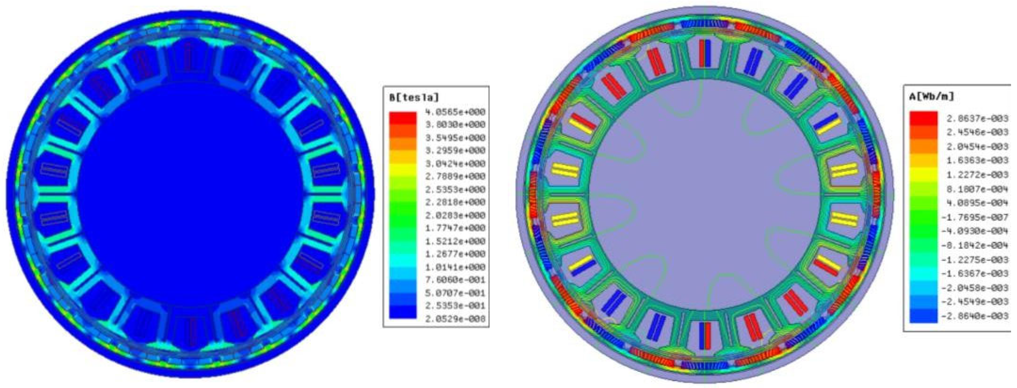
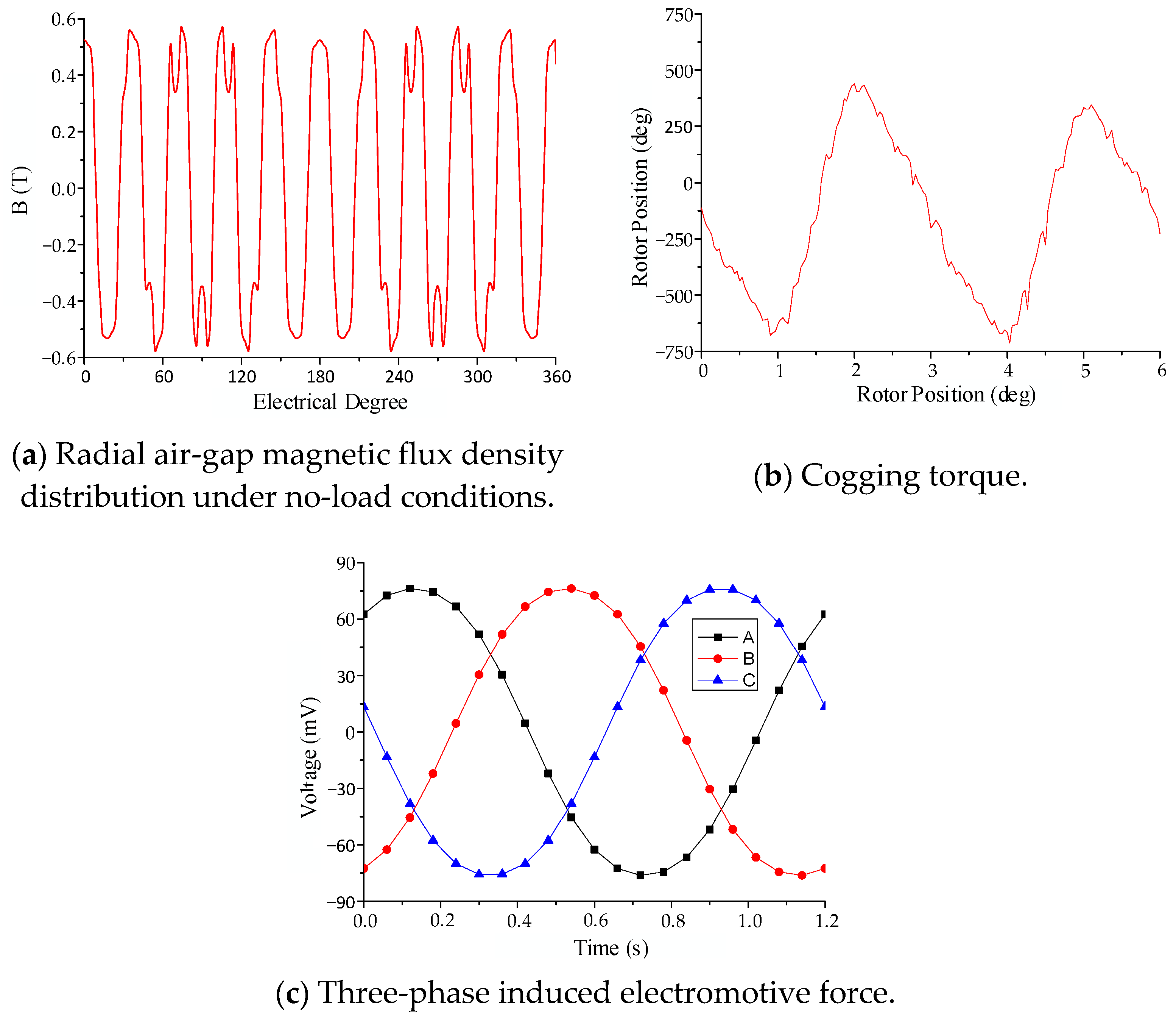
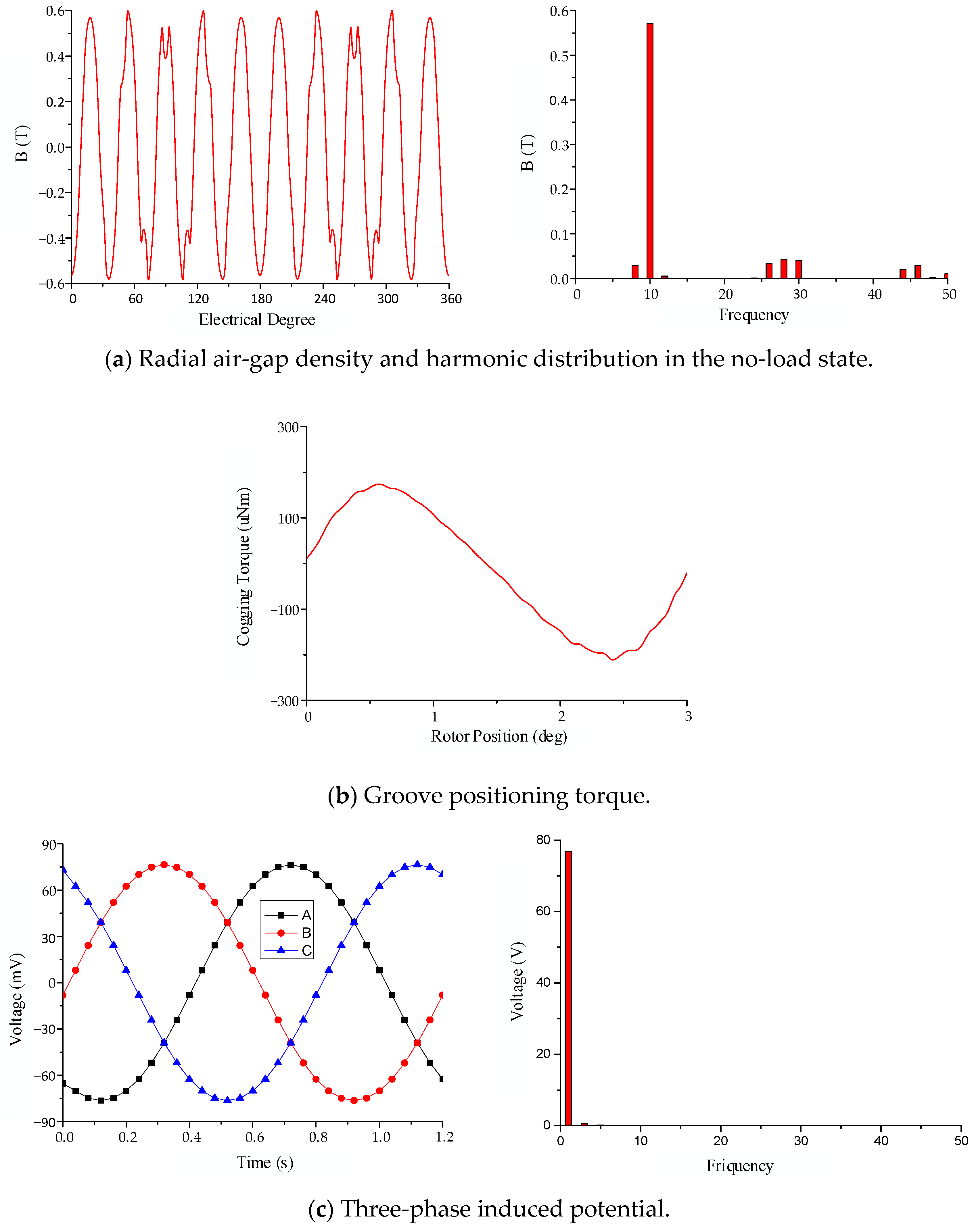
The electromagnetic performance of Halbach-type and olive-shaped magnet motors was rigorously analyzed under no-load conditions at a rotor speed of 30°/s. The magnetic flux density and flux line distributions were computed for both designs. For the Halbach-type motor, these parameters are depicted in
Figure 5, showcasing the radial magnetic flux density and three-phase back EMF. Cogging torque is presented in
Figure 6. The comparative analysis reveals distinct differences in magnetic field uniformity and torque ripple, with the olive-shaped magnet structure delivering superior flux concentration and smoother performance at low speeds.
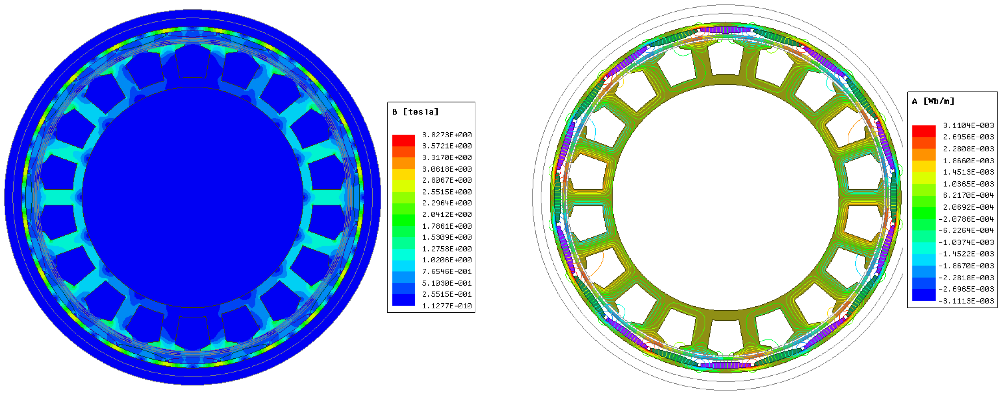
In contrast, the olive-shaped magnet motor, as shown in
Figure 7 and
Figure 8, demonstrates superior characteristics, with enhanced radial magnetic density distribution and improved cogging torque performance. These improvements are attributed to the optimized magnet arrangement, which results in a more uniform magnetic field and reduced torque ripple. Furthermore, the analysis reveals that the olive-shaped magnet motor exhibits lower energy losses and higher overall efficiency at low speeds, making it a more suitable choice for applications requiring precise and stable operation. These comparisons highlight the olive-shaped magnet motor’s better performance in design, efficiency, and operational stability under no-load conditions.
3.1.2. Analysis Under the Continuous Stall (1°/s) Condition
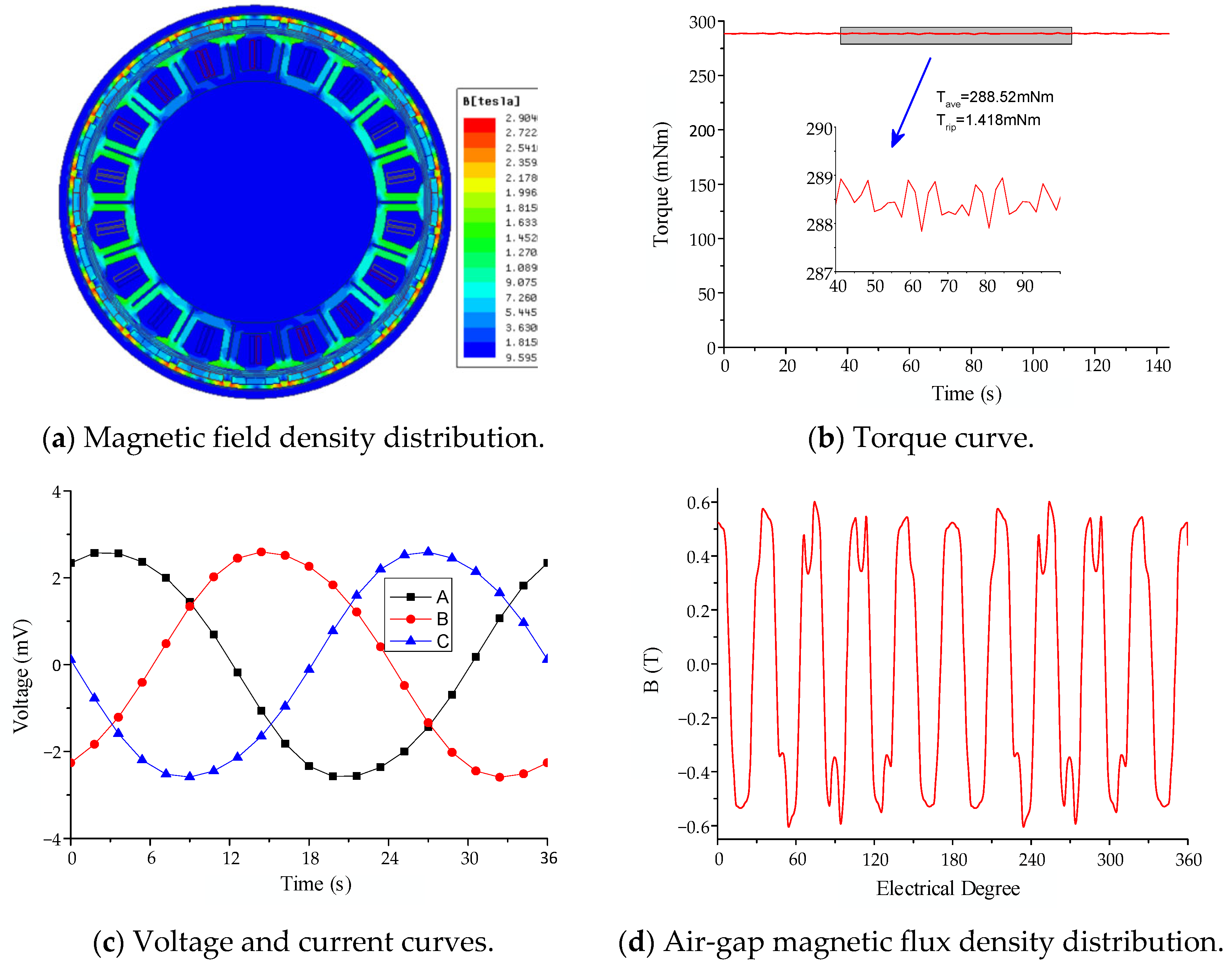
In the analysis of the Halbach-type motor under locked rotor conditions with three-phase sinusoidal currents, the motor’s magnetic flux distribution, torque characteristics, voltage–current relations, and radial air-gap magnetic field distribution were computed, as depicted in
Figure 9. The analysis also investigates the motor’s electromagnetic losses, efficiency, and thermal performance under continuous stall conditions, which are critical for optimizing motor design for prolonged operation in industrial applications.
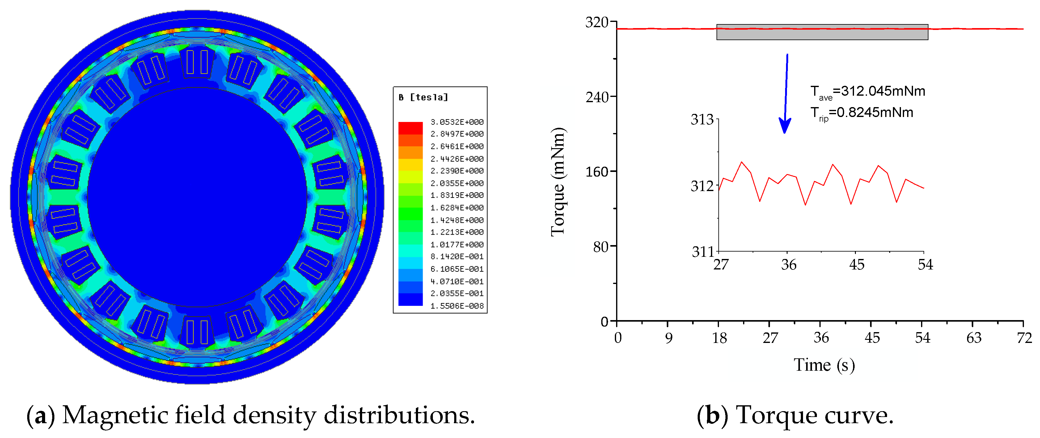
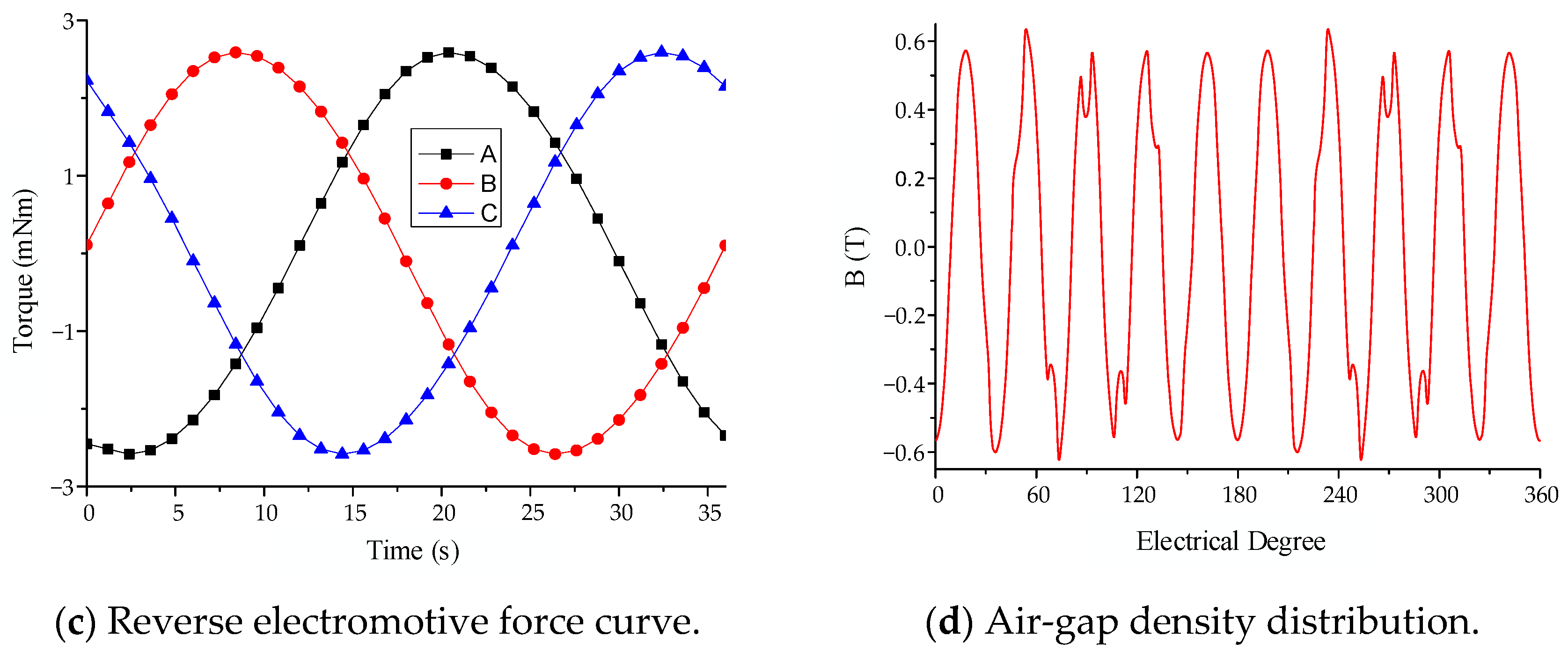
The olive-shaped magnet motor, operating at 1°/s, exhibited superior performance, with enhanced magnetic flux density, torque characteristics, and air-gap radial magnetic flux density waveform, as depicted in
Figure 10. It also demonstrated improved efficiency, reduced electromagnetic losses, and greater long-term reliability. Comparative analysis confirms that the olive-shaped magnet motor outperforms the Halbach-type motor under continuous stall conditions, offering significant advantages in flux concentration, torque smoothness, and overall stability, making it highly suitable for demanding industrial applications.
3.2. Torque and Its Fluctuation at Different Speeds: Analysis and Comparison of Halbach-Type and Olive-Shaped Magnet-Type Motors
Figure 11 depicts the relationship between motor output torque, torque pulsation, and rotational speed. For output torques exceeding 70 mN·m, torque pulsation remains below 1%, stabilizing at approximately 0.3% for torques above 200 mN·m, indicating robust performance at low speeds.
The olive-shaped magnet motor design delivers superior magnetic flux distribution compared to the Halbach-type motor, optimizing flux utilization. This results in smoother torque output with minimized pulsation. The olive-shaped motor achieves a peak torque of 0.312 N·m with a pulsation of 0.9 mN·m, maintaining an amplitude below 0.3% and demonstrating a 20% improvement compared to the Halbach-type motor’s pulsation of 1.15 mN·m.
The back EMF of the olive-shaped motor is nearly sinusoidal, in contrast to the Halbach-type motor, which shows greater distortion, leading to inefficiencies. Moreover, the air-gap magnetization in the olive-shaped motor remains stable under different loads with minimal distortion, ensuring consistent performance across diverse operational conditions. This stability greatly enhances its efficiency, particularly in low-speed operations where torque ripple and load fluctuations are most significant. The olive-shaped motor’s superior performance underscores its suitability for applications requiring smooth operation, high efficiency, and reliability.
Figure 10 further confirms the olive-shaped magnet motor’s superiority, illustrating reduced torque pulsation and magnetic harmonics, making it ideal for high-precision applications such as control moment gyroscope (CMG) systems. This optimized design delivers consistent and stable performance at low speeds, establishing it as the preferred choice for external frame motors requiring precision and reliability. The olive-shaped magnet motor surpasses the Halbach-type motor, providing enhanced torque smoothness, reduced pulsation, and more efficient load handling, which is optimal for low-speed, high-precision applications.
5. Conclusions
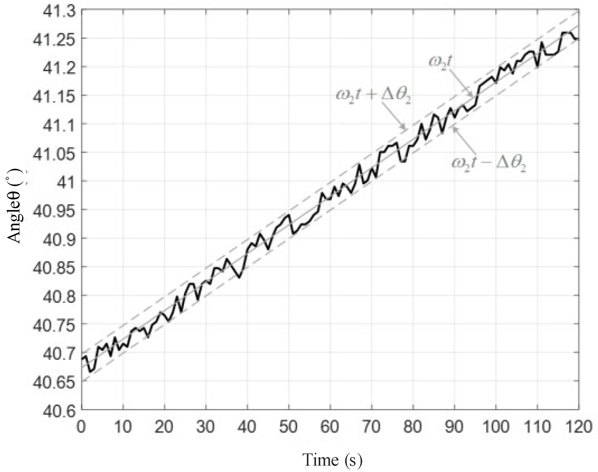
This study thoroughly investigated low-speed external frame motors with Halbach-type and olive-shaped magnet structures for control moment gyroscope (CMG) applications, fulfilling the reviewer’s request for a clear numerical summary and in-depth analysis. Finite element analysis (FEA) and experimental validation demonstrate that the olive-shaped magnet motor surpasses the Halbach-type configuration, achieving a peak torque of 0.312 N·m with a torque pulsation of 0.9 mN·m, demonstrating a 20% improvement compared to the Halbach-type’s pulsation of 1.15 mN·m, while maintaining pulsation below 0.3%. At ultra-low speeds of 0.05°/s and 0.005°/s, the olive-shaped motor sustains over 95% of the position curve within the error envelope, with a static error of ±0.1°/s at 0.5°/s, evidencing its exceptional precision and stability. The optimized magnetic field distribution minimizes cogging torque to 3 mN·m and ensures a highly sinusoidal back-electromotive force, enhancing efficiency compared to the Halbach-type’s less uniform flux and higher ripple, aligning with research on magnet geometry optimization. The olive-shaped design’s improved manufacturability addresses the Halbach-type’s complexity, offering cost-effective scalability for aerospace applications. Nevertheless, future research should explore thermal effects and material degradation to ensure long-term reliability. These results establish the olive-shaped magnet motor as a superior solution for high-precision, low-speed applications, contributing significantly to advancements in motor design and CMG performance.


