Abstract
In regions where electric vehicles (EVs) are widely adopted and charging stations (CSs) are being built in large numbers, CSs are becoming a critical load-side resource for low-inertia power systems. In this paper, a physics-data fusion enhanced frequency control strategy for multiple CSs is proposed. Firstly, the power grid frequency control architecture is improved, where CSs as multi-agent (MA) can participate in frequency response (FR). Besides, a physics-driven adaptive inertia for CS virtual synchronous generators (VSGs) is proposed to improve system dynamic FR characteristics. Building upon this, the physics-data fusion concept is introduced, wherein the MA-soft-actor-critic (MA-SAC) algorithm dynamically adjusts coordination coefficients with the consideration of CSs’ FR capabilities. To validate the proposed strategy, comparative case studies are conducted on the IEEE 39-node system. The simulation results demonstrate that compared to a single physics-driven method, the proposed control strategy exhibits enhanced adaptability and improved FR characteristics across various scenarios. Under intact MA communication conditions, the proposed strategy reduces the frequency disturbance index to 49.872% and the CS response power oscillation index to 79.542%; Even with MA communication impairments, the strategy maintains significant improvements, reducing these indexes to 48.897% and 86.733% respectively.
1. Introduction
Electric vehicles (EVs) have gradually replaced traditional fuel-powered vehicles, emerging as a crucial mode of transportation [1,2,3]. Besides, the rapid development of vehicle-to-grid (V2G) charging piles enables EVs can function as a critical load-side resource to provide frequency response (FR) [4,5].
Meanwhile, with the large-scale access to renewable energy sources from sustainable energy systems [6], the inertia of the new power system is declining. Therefore, the power system’s frequency is easier to rapidly change in response to disturbances, leading to significant safety risks [7]. Therefore, virtual synchronous generators (VSGs) have become a matter of great concern. VSG can provide inertia support to the new power system, effectively slowing down the rate of frequency change [8,9].
Given the above context, the application of inertia control strategies within CSs to enhance FR performance has emerged as a critical research direction in the energy field [10,11]. The traditional VSG control strategy with constant parameters can provide inertia to the system nodes but loses part of the dynamic regulation ability [12]. Therefore, many scholars have researched in the field of VSG inertia adaptive adjustment. Ref. [13] analyzed the correlation between frequency change and inertia coefficient and proposed a VSG control strategy with adaptive virtual inertia. Refs. [14,15] applied a fuzzy controller to the VSG control strategy to realize adaptive virtual inertia. However, these control strategies only focus on improving frequency dynamic characteristics under a single VSG. The FR capability of an individual CS is insufficient to improve the FR effect. Additionally, for CSs participating in FR, inertia adjustments in the aforementioned strategies do not consider the variations and differences in different CSs’ FR capabilities.
The multi-VSG dynamic characteristics interact with each other, causing frequency and CS response power oscillations of each node [16,17], which seriously depletes EV battery usage life. In recent years, the research about multi-VSG control can be divided into two types: physics-driven and data-driven.
For physics-driven methods, some scholars modified the VSG control strategy with adaptive control, fuzzy control, and optimization algorithms. Ref. [18] used a particle swarm optimization algorithm to optimize VSGs’ control parameters. However, the optimized parameters cannot be changed in real time. Ref. [19] proposed a cooperative virtual inertia control strategy for multiple energy storage stations (ESSs) to coordinate state of charge (SOC) balance and inertia enhancement. Ref. [20] analyzed the relationship between frequency and inertia and proposed a multi-CS control strategy based on adaptive virtual inertia. However, the adaptive inertia in the aforementioned single physics-driven methods relies solely on fixed equations and constant coordination coefficients for CS VSGs. This diminishes the accuracy of inertia adjustments, affecting frequency control performance and adaptability under various FR scenes, particularly in situations involving communication interruptions.
Therefore, for the design of an adaptive VSG control strategy, the deep reinforcement learning (DRL) algorithm which does not depend on specific models has received widespread attention in recent years [21,22]. DRL can achieve effective data accumulation through interaction with the environment to evolve control effects continuously in the training process. It can be divided into two categories. The first category is the value-based method, such as deep Q-network [23]. However, the deep Q-network action space is discrete. When deep Q-network is applied in inertia control, the virtual inertia changing value is discretized, influencing the system FR dynamic performance. The second type is the policy gradient method [24], which is suitable for continuous high-dimensional action space. Ref. [25] took the active power output, angular frequency, and its derivatives as observations, and transformed the optimal VSG adaptive control problem into a deep deterministic policy gradient problem. However, the action selection of deep deterministic policy gradient, as a deterministic strategy algorithm, is limited [26]. Ref. [27] proposed a load frequency control method based on proximal policy optimization to optimize the balance between generation cost and frequency stability in an isolated microgrid. However, proximal policy optimization, as an on-policy algorithm, depends on sample size and its effectiveness.
The soft actor-critic (SAC) algorithm not only introduces action entropy to let action output be dispersed without missing useful actions in the training process but also applies an experience playback pool to enhance sample utilization. Therefore, Ref. [28] introduced SAC to train an agent based on the active power and frequency as state input to output virtual inertia adjustment actions for the optimal FR. However, the above literatures only use a single agent to take a VSG as a single control object. When several CSs are connected to the power system, the training time and dimension under a centralized control architecture will increase exponentially [29]. The multiagent-DRL (MA-DRL) method has good expansibility, and can effectively solve multiple control objects problem through decentralized implementation. Ref. [30] proposed a distributed dynamic inertial droop control strategy based on MA-DRL for multiple ESSs. However, this single physics-driven method focuses on directly adjusting inertia for ESSs and is not suitable for CSs. Firstly, due to the varying EV users’ charging demands, CSs’ FR capabilities vary frequently compared to those of ESSs. Additionally, unlike ESS batteries participating in FR, the service life of EV batteries is more susceptible to degradation from frequent charge and discharge cycles. Consequently, the diversity of CS FR scenes complicates the training environment, which negatively impacts the learning efficiency of single data-driven methods that lack a priori knowledge.
Therefore, unlike previous studies that either rely solely on fixed equations under a single physics-driven method, diminishing the accuracy of inertia adjustments or ignore the complexity of FR scenes involving CS participation, which impacts the learning efficiency of a single data-driven method, this paper proposes a physics-data fusion enhanced VSG control strategy for multiple CSs active FR. The main contributions of this paper are drawn as follows:
- (1)
- This paper incorporates a power grid frequency control framework with multiple CS VSGs participation based on physics-data fusion driven. Through MA communication of this framework, the application basic of the reinforcement learning method in CS VSG control is constructed, which considers the variations and differences in CS FR capabilities.
- (2)
- The relationship between the angular velocity changes of multiple CS VSGs and their inertia are integrated into the data-driven method as prior knowledge. The agent learning efficiency, interpretability for FR effect improvement, and generalization for unknown scenes are enhanced under the power grid frequency control framework with multiple CS VSGs participation.
- (3)
- The proposed control strategy utilizes the MA-SAC algorithm to dynamically adjust the coordination coefficients between CS VSGs. The MA-SAC achieves the cooperative control idea of “centralized training and decentralized execution” to improve adaptability under various FR scenes, including situations with communication interruptions.
2. Power Grid Frequency Control Architecture with Distributed CSs Participation
When power disturbance occurs, the energy control centers (ECCs) in the CSs can change the charging power of EVs through V2G charging piles. To achieve the above process, it is necessary to incorporate multiple CSs into a power grid frequency control framework.
2.1. Frequency Control Architecture of Power Grid with the CS Participation
In recent years, many scholars have researched on CS FR capability evaluation method [10,31] and V2G response model [19,32], making CSs a vital frequency regulation resource in the power grid frequency control architecture. Based on the EV users’ charging demand and EV message, the boundary of the CS response power , including CS equivalent power generation capability Δ and CS equivalent load capability Δ can be aggregated by the CS FR capability evaluation method. Furthermore, based on the frequency situation, the CS response power can be distributed among EVs in the CS by the V2G response model.
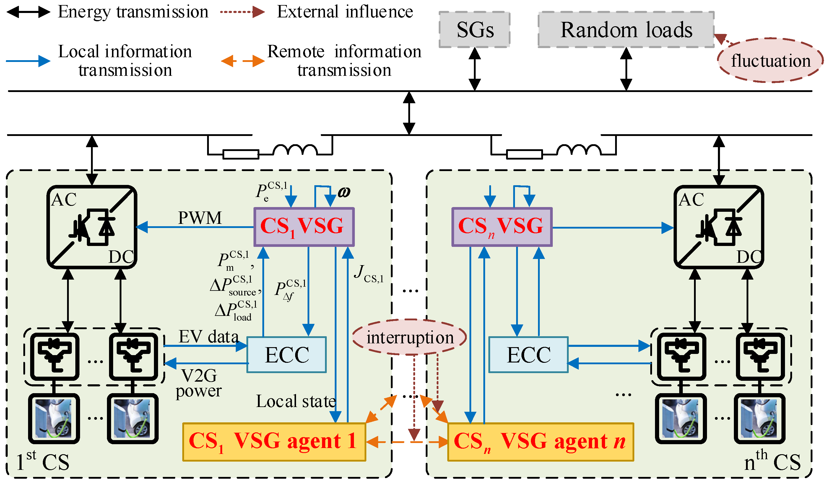
To further improve the power grid frequency control architecture with CS participation based on the above research, this paper focuses on adaptive inertia design for CS VSG. CS participation in frequency response control architecture in this paper is shown in Figure 1, where each CS is equipped with an ECC, a CS VSG controller, and a CS VSG agent. ECC can evaluate each EV’s FR capability based on EV users’ charging demands received from charging piles. Then CS FR capability including CS equivalent power generation capability Δ and equivalent load capability Δ can be aggregated. Based on Δ, Δ, rotor angular velocity ω, CS VSG electromagnetic power received from the corresponding node, and original charging power plan , CS VSGs can respectively output CS response power to the ECC and the PWM signal to CS grid-connected inverter to provide inertia for the power system. Based on , the ECCs control V2G charging piles to adjust EVs’ charging plans.
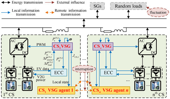
Figure 1.
CS participation in frequency response control architecture.
2.2. Information Interaction Modeling for Distributed CSs
Based on graph theory knowledge, the communication topology graph of an MA system composed of n agents can be represented by directed graph G = (V, E, A), where V = (V1, V2, …, Vn) is a node set; E ⊆ V × V is an edge set; communication topology A = [bij]n×n is an adjacent matrix, and diagonal elements bii = 0, i = 1, 2, …, n. When the directed edge Eij = (Vi, Vj) ∈ E, bij = 1; otherwise, bij = 0.
In the context of graph theory, a CS equipped with a VSG agent can be modeled as a node within a network [20,30]. Under 5G communication technology, communication delay can be ignored when some CSs’ communication distance is within a certain range [20]. This technological advantage enables CS VSG agents can exchange information.
Assuming that CSi VSG agent i can receive information from CSj VSG agent j, CSj VSG agent j is defined as an adjacent agent (AAG) of CSi VSG agent i, and CSi VSG agent i is defined as the leading agent (LAG) of CSj VSG agent j. If this communication mode is two-way, CSi VSG agent i and j are an AAG and a LAG to each other, bij = bji = 1. When the communication channel between CSi VSG agent i and j is suddenly interrupted, bij and bji change from 1 to 0.
Based on the above background knowledge, the adjustment process of the LAG to the inertia of the local CS VSG can be described in Figure 2. In Figure 2, based on the communication topology A, CS VSG agents can exchange state information. Then, according to the state information received from local CS VSG and AAGs, LAG can reasonably adjust local CS VSG’s inertia to enhance the dynamic adjustment ability of the power system. In the following sections, the relationship between inertia adjustment and state message is specified.
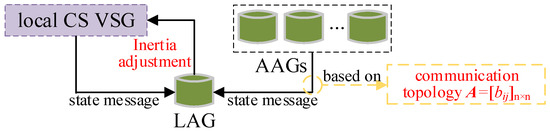
Figure 2.
The adjustment process of the LAG to the inertia of the local CS VSG.
3. Adaptive CS VSGs Control Strategy
VSG control can simulate synchronous generator (SG) inertia characteristics and act on CS grid-connected inverter to provide inertia support for power system nodes to improve FR characteristics. Moreover, adaptive inertia design can enhance the system’s dynamic response performance.
3.1. The Basic Principle of GFM VSG
The grid-connected characteristic of the converter applied VSG technology is determined by its control mode, based on which, it is generally divided into two categories: grid-following (GFL) VSG and grid-forming (GFM) VSG [33]. The converter synchronization mode under GFL VSG is to measure the parallel point’s frequency by a phase-locked loop and adjust the output power to follow the power grid. Therefore, GFL VSG essentially shows current source characteristics, so there is a certain time delay in the control mechanism. For GFM VSG, the electric potential frequency is not determined by power grid frequency, but by active power control loop to realize the synchronization with the power grid. Therefore, GFM VSG shows the voltage source characteristics to construct frequency independently. Its theoretical time delay is almost zero, so GFM VSG is more suitable for CS to participate in FR.
The active power-frequency GFM VSG control equations are listed as follows:
where J is virtual inertia; D is damping coefficient; ω is rotor angular velocity; ω0 is synchronous rotor angular velocity; Pe is electromagnetic power; Pm is prime mover power; PΔf is response power; Pm and PΔf form active power instruction Pref.
3.2. A Primary FR Controller Considering CS FR Capability
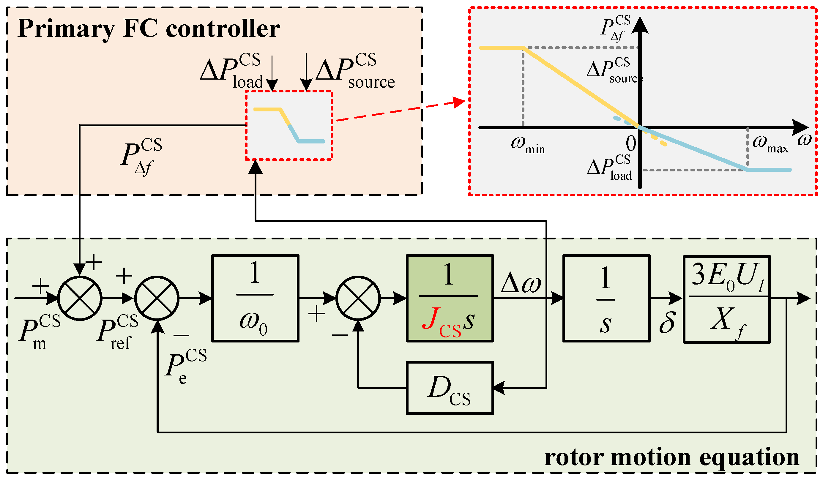
GFM VSG can be applied in CS to form CS VSG, and a primary FR controller considering CS FR capability is designed to apply in CS VSG, which is shown in Figure 3. In Figure 3, JCS and DCS are respectively CS VSG virtual inertia and damping coefficient; composed of and is CS VSG active power instruction transmitted to ECC to adjust charging plans; E0 and Ul are CS VSG no-load electric potential and output voltage; Xf is filter reactance; s is Laplace transform operator.
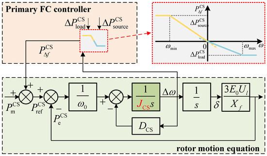
Figure 3.
The CS VSG control block diagram based on CS FR capability.
Besides, the proposed primary FR controller can adaptively adjust the droop coefficient based on CS FR capability. is bound by Δ and Δ; Δωmax and Δωmin are respectively the corresponding angular velocity offset boundary of ΔPCS source and Δ. Angular velocity offset Δω = ω−ω0. The equations of is established as follows:
where KΔf is the droop coefficient of CS response power; fn is rated frequency; Δfmax and Δfmin are the corresponding frequency offset boundary of Δ/Δ, respectively 0.2 Hz/−0.2 Hz. When Δω is between ωmin and ωmax, CS provides appropriate between Δ and Δ; when Δω exceeds the boundary of ωmin or ωmax, CS provides Δ or Δ to restrain frequency sudden change to reduce maximum frequency offset and reserve time for the secondary FR.
3.3. Physics-Driven Adaptive Inertia
When power disturbance happens, inertia differences lead to the system node dynamic FR difference, including frequency oscillation and CS response power oscillation. Therefore, this paper designs a physics-driven adaptive inertia control strategy.
Based on the Mason equation, Figure 3, and , it can be divided into two cases to analyze the second-order transfer function of CS VSG electromagnetic power by using the small signal model.
Case 1: when Δ ≤ ≤ Δ, that is Δωmin ≤ Δω ≤ Δωmax, the transfer function between and is as follows:
Case 2: when > Δ or < Δ, that is Δω > Δωmax or Δω < Δωmin, the transfer function of and is as follows:
When Δω < Δωmin, = + Δ; when Δω > Δωmax, = + Δ. It can be seen that Equations (6) and (7) are typical second-order transfer functions. When the error band is ±2%, the natural oscillation angular frequency ωn, damping ratio ξ, the overshoot σ%, and the adjustment time ts are obtained in Equations (8) and (9).
where D’ CS is CS VSG equivalent damping coefficient, which is divided into two cases, as shown in Equation (10). According to Equations (8) and (9), when JCS increases, ωn decreases, ξ decreases, σ% increases, and ts increases, which means the larger JCS can reduce the dynamic response oscillation for a single CS VSG.
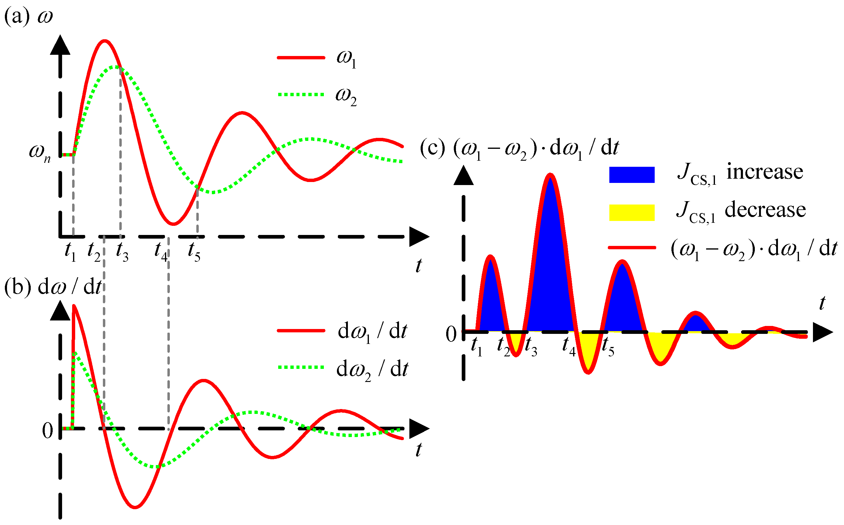
For multiple CS VSGs, the multi-VSG angular velocity oscillation curve is shown in Figure 4, taking CS1 VSG and CS2 VSG as examples to analyze JCS,1 adjustment. The curve can be divided into four intervals: (1) t1~t2, (2) t2~t3, (3) t3~t4, (4) t4~t5. In interval (1), if ω1 − ω2 > 0, dω1/dt > 0, and (ω1 − ω2)·dω1/dt > 0, JCS,1 should increase to slow down the ω1 increase and decrease ω1-ω2; in interval (2), if ω1 − ω2 > 0, dω1/dt < 0, and (ω1 − ω2)·dω1/dt < 0, JCS,1 should decrease to speed up the ω1 recovery and decrease ω1 − ω2. Similarly, JCS,1 increases and decreases respectively in intervals (3) and (4). Besides, the change of JCS,2 should be on the contrary compared with JCS,1.
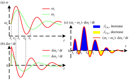
Figure 4.
Multi-VSG angular velocity oscillation curve. (a) CS VSGs’ rotor angular velocity. (b) CS VSGs’ rotor angular velocity rate of change. and (c) The product of the rotor angular velocity deviation and rate of change for CS1 VSG.
The above content only considers two CS VSGs. In multiple CS VSGs, any CS VSG inertia adjustment needs to consider the comprehensive influence of its AAGs. So its adaptive equation and CS VSGs’ coordination matrix K are established as follows:
where JCS,i,0 is CSi VSG initial virtual inertia; ki,j is coordination coefficient, respecting the influence degree of the CSj VSG on CSi VSG’s inertia; Ci is the total number of AAGs for CSi VSG agent i; Zi,j is the serial number of jth AAG of CSi VSG agent i.
4. CS VSGs Control Strategy Based on Physics-Data Fusion Model
The establishment equation of adaptive inertia in Section 3 is not complete. It equates the influence degrees of AAGs to LAGs’ inertia. Therefore, it is necessary to introduce a data-driven method to adjust coordination coefficients, enhancing adaptability to reduce frequency oscillation and CS response power oscillation.
4.1. Physics-Data Fusion Modeling
The physics-driven adaptive inertia has rigidity based on mechanism analysis, but the model construction is too idealized. It is impossible to distinguish the difference in AAGs’ influence on LAGs, reducing inertia adjustment accuracy. Therefore, it is difficult to reduce frequency oscillation and CS response power oscillation. The data-driven model is flexible based on experience playback, which is suitable for complex scenes. However, in the scene where CSs participate in FR, the diversity of CS FR capabilities, communication situation, and power disturbances would lead to low training efficiency when lacking a priori analysis, making actions to adjust virtual inertia confusing.
Given the respective limitations of a physics-driven method and a data-driven method, a physics-data fusion model that integrates mechanistic rules with experience playback can be more effectively applied to CS participation in frequency response control architecture. By applying reinforcement learning to optimize coordination coefficients within the physics-driven adaptive CS VSG inertia, this approach not only enhances the accuracy of inertia adjustments by distinguishing the differential impacts of AAGs on LAGs but also improves MA training efficiency through the incorporation of a priori knowledge.
4.2. SAC Basic Principles
This paper uses the MA-SAC to achieve the cooperative control idea of “centralized training and decentralized execution”, respectively adjusting coordination coefficients between CS VSGs. The SAC discount cumulative reward function M is as follows:
where πβ is agent action strategy, reflecting the probability distribution of agent action selection; st and at are respectively the state and action taken by the agent at t; E[·] is the mathematical expectation; (st, at)~ρπ represents the distribution of trajectories (st, at) under the strategy π; r(st, at) is the reward value based on at and st; α is a regularized entropy parameter, determining the entropy importance and the strategy exploratory. H(πβ(|st)) is action entropy of strategy π under state st; β is the network parameter of πβ.
The SAC actor network is responsible for modeling the action strategy πβ, and the critic network evaluates the strategy by Q-value function Qθ(st,at), defined as follows:
where Qθ(st,at) is the sum of the expected discount reward and the expected action entropy from the state-action (st, at) to the end; e is the reward discount factor; Est+1~ρπ represents the sum of the expected values of all states st+1 under the trajectory ρπ.
The SAC algorithm consists of three neural networks, that is actor network, critic network, and target critic network. Their parameters are respectively updated as follows:
where Mπ(β) and MQ(θ) are respectively loss functions with parameters β and θ as the independent variable; D is the experience playback pool; τ is the update coefficient.
4.3. Adaptive Virtual Inertia Modified by Physics-Data Fusion
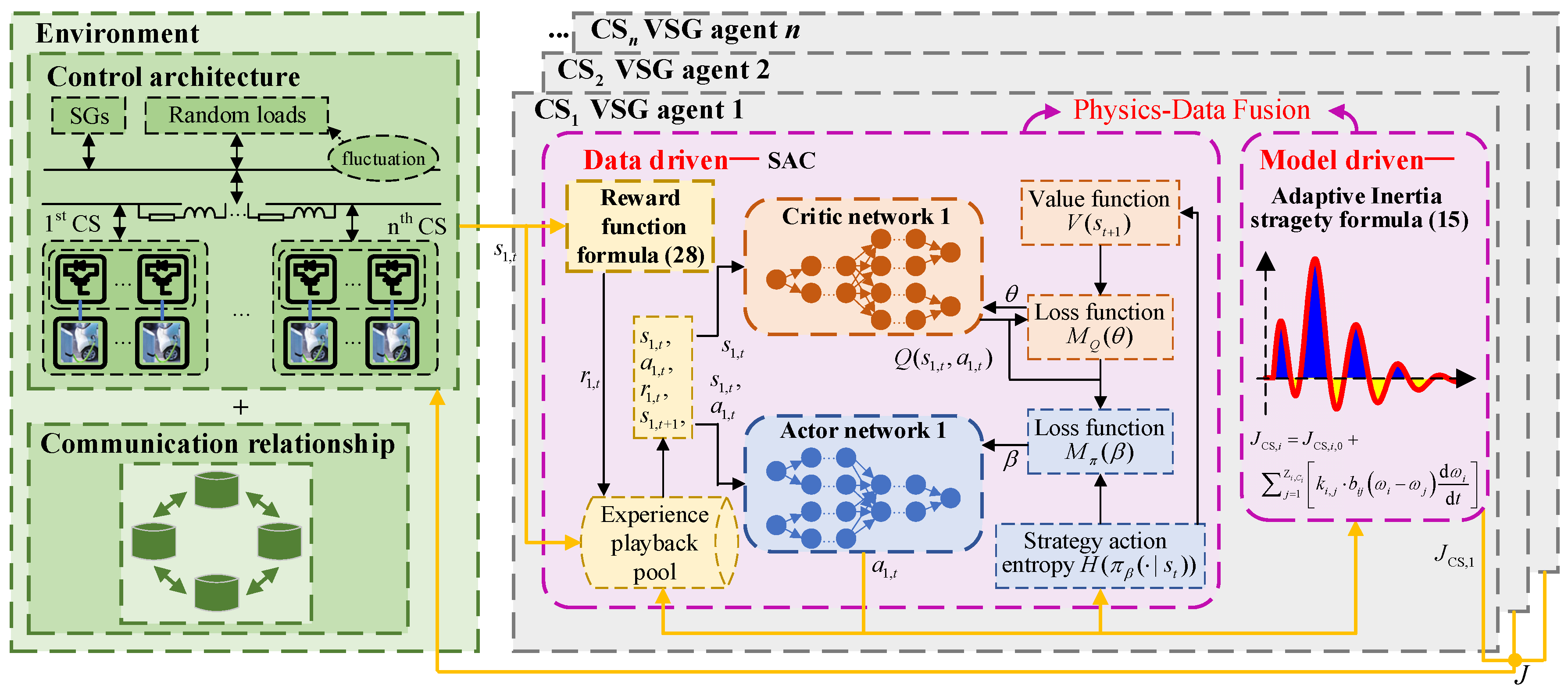
The power grid frequency control framework with multiple CS participation based on physics-data fusion driven is shown in Figure 5, including environment and CS VSG agents. The former includes the power grid frequency control architecture with CS participation and CSs’ communication topology. The latter can interact with the environment and obtain information from AAGs based on the communication topology. si,t, ai,t, and ri,t, are respectively defined below:

Figure 5.
Power grid frequency control framework with multiple CS VSGs participation based on physics-data fusion driven.
- (1)
- state:
- (2)
- action:
- (3)
- reward:
During the training process, by the interaction with the environment, MA can gradually reasonably adjust corresponding coordination coefficients with consideration of CS FR capabilities to improve inertia adjustment accuracy. Then the rewards are gradually maximized, so different nodes’ frequency oscillation is restrained. Besides, restraining the frequency oscillation can also reduce the response power oscillation, preventing EVs in the CS from switching the states frequently to protect EV battery service life.
4.4. Assessment Index
To compare the control effect with other control strategies, some assessment indexes are designed as follows.
where Ri is the frequency offset square sum of CSi VSG node and other CS VSGs nodes; Vi is the sum of CSi response power oscillation absolute value; Rall/Vall is the sum of Ri/Vi (i = 1, 2, …, n); Δfi(t) is the frequency offset of CSi VSG node relative to the rated frequency at the time t; t0 is simulation start time; t1 is simulation end time; is CSi VSG response power at the time t; Δt is the interval time for CS response power comparison. When different control strategies are applied in CSs, the smaller Ri or Rall is, the smaller different nodes’ frequency offsets are; the smaller Vi or Vall is, the less frequently the EV status is switched and the less EV battery loss is.
5. Results and Discussion
The effectiveness of the proposed strategy in this paper is verified by the following simulation. Section 5.1 gives the simulation scene; Section 5.2 gives the MA training situation. Section 5.3 compares the proposed control strategy with traditional CS VSGs and adaptive CS VSGs control strategy.
5.1. Simulation Scene
To verify the proposed strategy, four CS VSGs are used to replace the SGs at nodes 31, 33, 36, and 39 in the IEEE 39-node system. The four CS VSGs’ initial inertia information and communication topology are shown in Table 1. The IEEE 39-node system after CS VSGs replacement is shown in Figure 6, where 1−39 represent the network nodes.

Table 1.
CS VSGs message.
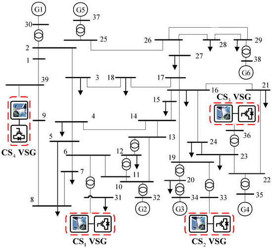
Figure 6.
IEEE 39-node system after CS VSGs replacement.
Besides, disturbance load, communication topology, and CSs’ FR capabilities should be considered to establish random scenes: (1) Load disturbance: load disturbance ranging from −1 MW to 1 MW is randomly generated in load nodes; (2) Communication topology: the communication between CS2 VSG agent and CS3 VSG agent is weak, in which there is a 10% probability of interruption, that is b2,3 and b3,2 change from 1 to 0; (3) CSs’ FR capabilities: 24 situations are set to simulate four CSs’ FR capabilities’ difference and variability for every hour of one day. Then 200 groups of scenes are randomly generated, and the training set and test set are divided at the proportion of 3:1.
Additionally, the hyperparameter settings for each CS VSG agent are the same, as shown in Table 2. The software running the simulation is MATLAB/Simulink 2023a, which is configured on a computer with a 13th Gen Intel (R) Core (TM) i9-13900F CPU (32 GB).
Table 2.
SAC parameters.
5.2. The MA Training Process
The value range of each parameter in the action ai,t is set as [0, 6 × 10⁵], and the training set is cycled for four CS VSG agents’ training. The four agents’ reward training curves under the proposed control strategy are shown in Figure 7. The dark green curves represent the average cumulative reward value of nearly 150 training episodes, and the light green curves represent the cumulative reward value in each episode. Besides, to verify the proposed control strategy with prior knowledge has better learning efficiency, the four agents’ reward training curves under a single data-driven method are shown in Figure 8. The SAC parameters of the proposed strategy and a single data-driven method are the same.
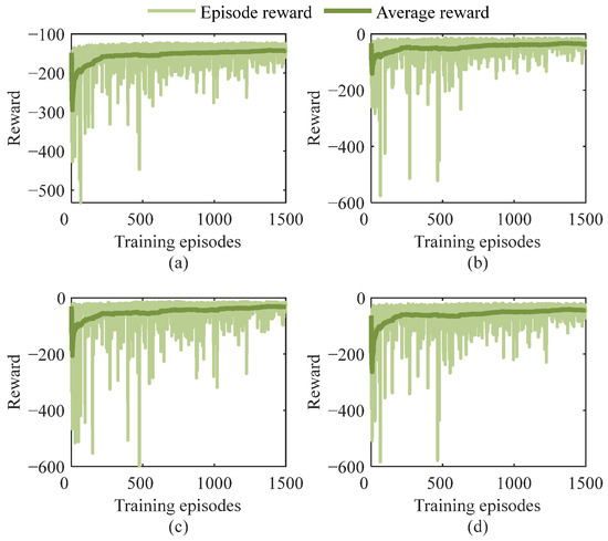
Figure 7.
Four CS VSG agents’ reward training curves under the proposed strategy. (a) CS1 VSG agent 1. (b) CS2 VSG agent 2. (c) CS3 VSG agent 3. and (d) CS4 VSG agent 4.
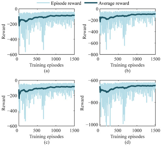
Figure 8.
Four CS VSG agents’ reward training curves under a single data-driven method. (a) CS1 VSG agent 1. (b) CS2 VSG agent 2. (c) CS3 VSG agent 3. and (d) CS4 VSG agent 4.
In Figure 7, for the proposed control strategy, CS VSGs’ coordination coefficient adjustments are disordered during the first 500 training episodes, leading to inertia adjustment disorder, which makes the reward value small. With the MA-SAC training, CS VSGs’ coordination coefficient adjustments gradually tend to be reasonable, leading the reward value to increase gradually, and the value is stable after 1200 training episodes. In Figure 8, for a single data-driven method, inertia adjustments are still disordered during the first 750 training episodes and the reward value is not stable after 1500 training episodes.
Therefore, the above training results show that for the proposed control strategy, the CS VSG agents can not only achieve effective learning but also have better learning efficiency due to evolution interpretability in the prior knowledge under data-driven. Meanwhile, the power grid frequency control framework with multiple CS VSGs participation based on physics-data fusion driven proposed in this paper provides an application basic for the reinforcement learning method in CS VSG control.
5.3. Control Effect of the Proposed Strategy
The proposed strategy’s control is compared with traditional CS VSGs and adaptive CS VSGs control strategy. The CSs’ initial inertia and communication topology for these control strategies are shown in Table 1. The inertia of traditional CS VSGs control strategy is constant. Adaptive CS VSGs control strategy is established based on Section 3.3, and coordination coefficients are regarded as consistent, setting to 2 × 10⁵.
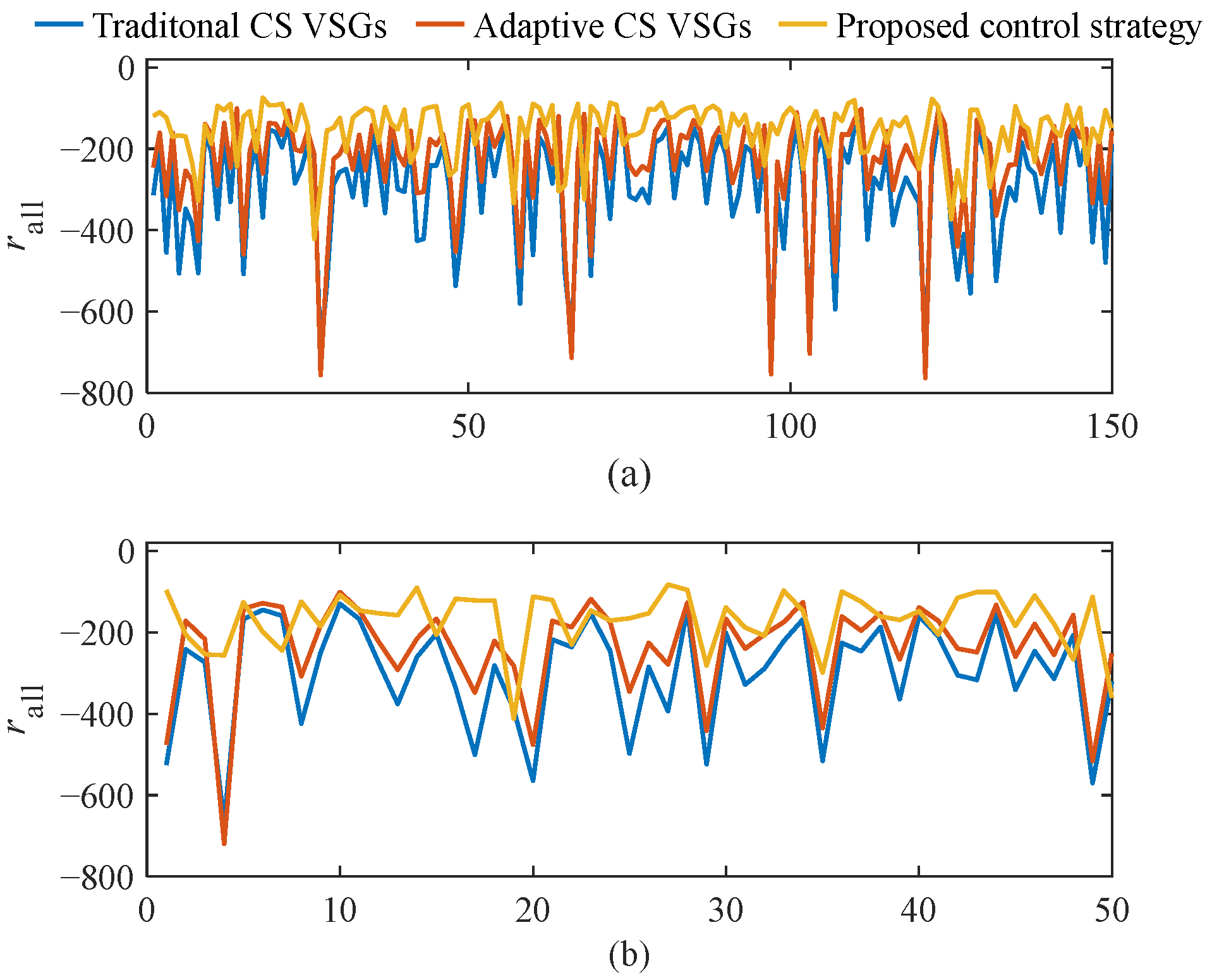
Firstly, 150 training scenes and 50 testing scenes are applied to the above three control strategies, their each scene’s cumulative reward is compared as shown in Figure 9. In Figure 9a, for the training set, the average rall of traditional CS VSGs control strategy, adaptive CS VSGs control strategy, and the proposed strategy are respectively −292.67, −236.04, and −154.26. In Figure 9b, for the testing set, the average rall of three strategies are respectively −298.43, −239.08, and −168.00. So average rall of the proposed strategy are respectively 65.353% and 70.269% of this of the adaptive CS VSGs control strategy for the training set and the testing set, meaning the proposed strategy has better adaptability under various FR scenes and generalization for unknown scenes. This is because the proposed strategy utilizes MA-SAC to adjust coordination coefficients with consideration of CS FR capability to achieve more accurate inertia adjustment.
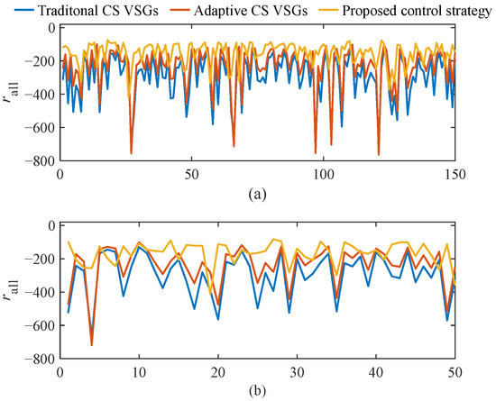
Figure 9.
Cumulative rewards comparison between the training set and test set. (a) Training set. and (b) Testing set.
To specifically reflect the proposed strategy’s validity in improving system FR effect and adaptability under different FR scenes, this paper constructs five cases. The load of 100 MW suddenly increases at node 25, and Δ of CS1, CS2, CS3, and CS4 are respectively 3.33 MW, 5.38 MW, 1.90 MW, and 5.41 MW. The control strategy applied in CS grid-connected inverters and communication topology for five cases are respectively as follows:
Case 1 applies traditional CS VSGs and the communication is intact as shown in Table 1; Case 2 applies adaptive CS VSGs and the communication is intact as shown in Table 1; Case 3 applies the proposed control strategy and the communication is intact as shown in Table 1; Case 4 applies adaptive CS VSGs and the communication is shown in Table 1 with the exception that the communication between CS2 VSG agent 2 and CS3 VSG agent 3 is interrupted; Case 5: applies the proposed control strategy and the communication is shown in Table 1 with the exception that the communication between CS2 VSG agent 2 and CS3 VSG agent 3 is interrupted.
5.3.1. Intact Communication
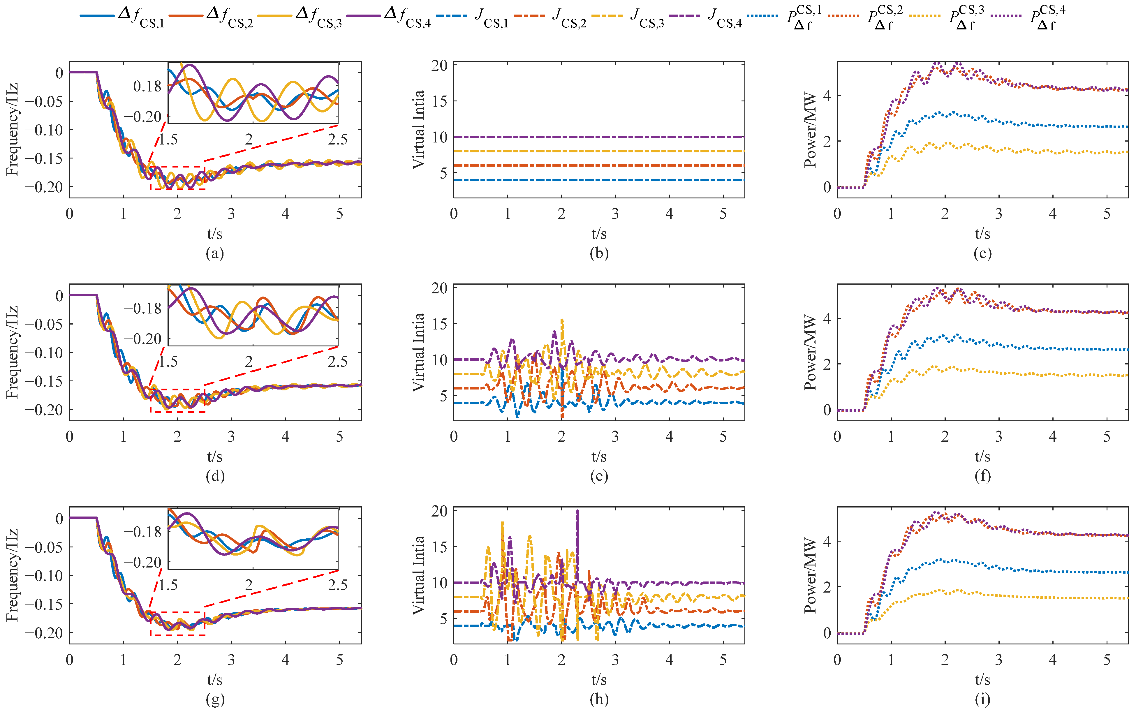
To verify the proposed control strategy can reduce different nodes’ frequency differences and CS response power oscillation, frequency, inertia, and CS response power for Case 1, Case 2, and Case 3 are shown in Figure 10.
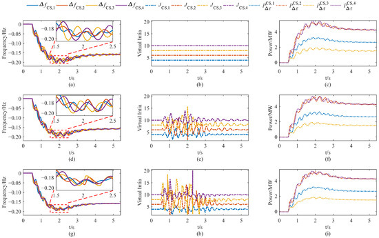
Figure 10.
Power system frequency, inertia, and CS response power for Cases 1–3. (a) Frequency under Case 1. (b) Virtual inertia under Case 1. (c) Response power under Case 1. (d) Frequency under Case 2. (e) Virtual inertia under Case 2. (f) Response power under Case 2. (g) Frequency under Case 3. (h) Virtual inertia under Case 3. and (i) Response power under Case 3.
Firstly, from the two red boxes in Figure 10a,d, it can be seen that the frequency offset between different nodes under the adaptive CS VSGs control strategy is less than that of the traditional CS VSGs control strategy. This is because adaptive CS VSGs can adaptively adjust CS VSGs’ inertia based on angular velocity offset and its change rate from its own CS VSG and its AAGs to suppress angular velocity difference, which can be seen in Figure 10e.
Moreover, from the two red boxes in Figure 10d,g, it can be seen that the frequency offset between different nodes under the proposed control strategy is less than that of the adaptive CS VSGs control strategy by further adjusting CS VSGs’ coordination coefficients. Meanwhile, in Figure 10c,f,i, CS response power oscillation of the proposed strategy is the weakest, preventing EVs in the CSs from switching charge state frequently, protecting EV battery service life.
5.3.2. Damaged Communication
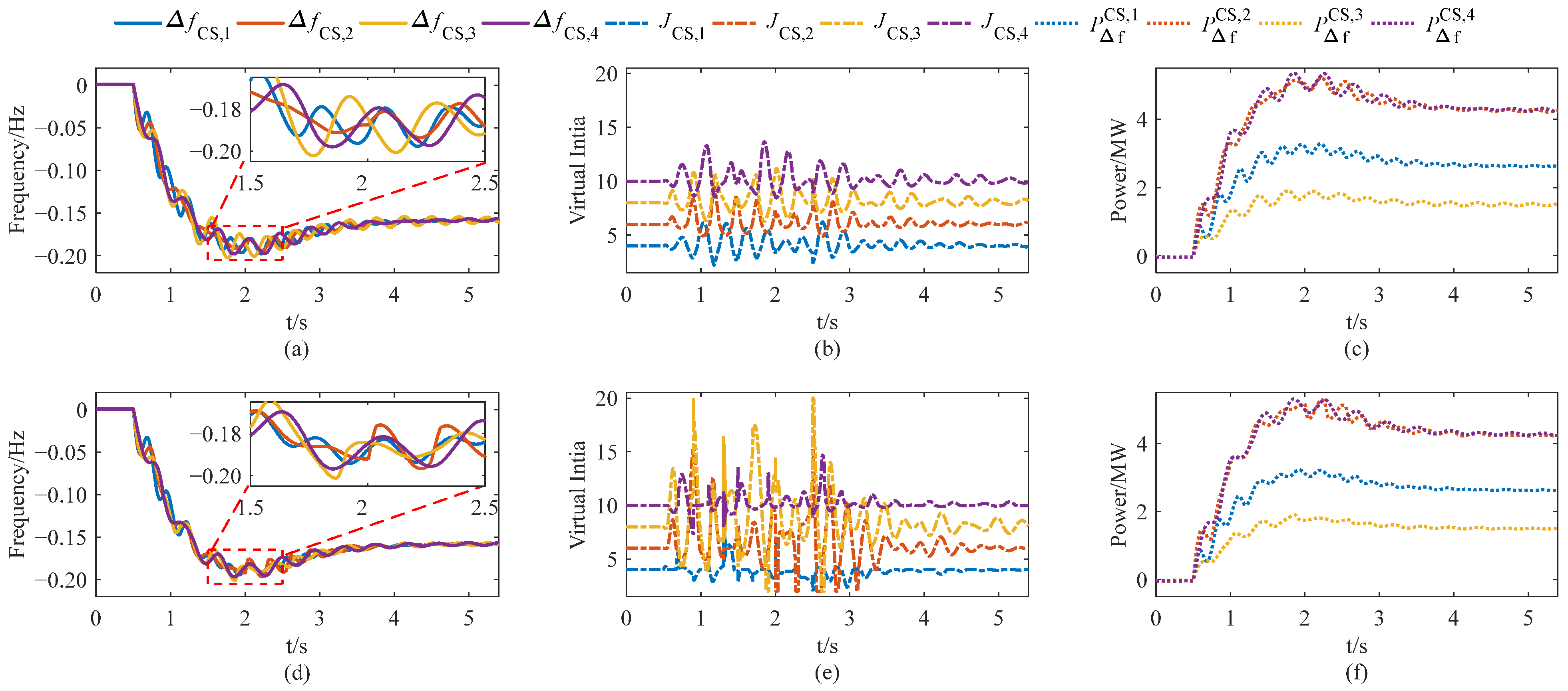
To verify the proposed control strategy’s adaptability under a communication interruption. This paper considers Case 4 and Case 5, in which the communication between CS2 VSG agent 2 and CS3 VSG agent 3 is interrupted. Frequency, inertia, and CS response power for Case 4 and Case 5 are shown in Figure 11.

Figure 11.
Power system frequency, inertia, and CS response power for Cases 4 and 5. (a) Frequency under Case 4. (b) Virtual inertia under Case 4. (c) Response power under Case 4. (d) Frequency under Case 5. (e) Virtual inertia under Case 5. and (f) Response power under Case 5.
Firstly, comparing with Figure 10d Case 2 and Figure 11b Case 4 which both apply adaptive CS VSGs, it can be seen that influenced by the communication interruption, inertia adjustment of CS2 VSG and CS3 VSG in Case 4 is reduced. Besides, comparing Figure 10h Case 3 and Figure 11e Case 5 which both apply the proposed control strategy, it can be seen communication interruption influence still exists but is reduced. Because the proposed control strategy can adjust coordination coefficient k21 and k34 respectively to realize compensation.
5.3.3. Assessment Index Comparison Under Different Cases
To further explain the proposed control strategy’s adaptability during a communication interruption, Table 3 shows the assessment index results in Cases 1–5.
Table 3.
Assessment Index Comparisons of Different Cases.
Firstly, for traditional CS VSGs, no matter whether the communication is interrupted or intact, there is no difference in the control effect. Because traditional CS VSGs’ inertia is constant, leading to the weak dynamic adjustment that Rall and Vall are respectively 49.322 Hz2·s and 35.503 MW·s, relatively large.
Besides, the adaptive CS VSGs control strategy is seriously affected by communication interruption. Rall under Case 4 increases obviously by 8.996% to 41.763 Hz2·s, compared with 38.316 Hz2·s under Case 2. Even Vall of adaptive CS VSGs control strategy under Case 4 increases by 1.023% to 35.870 MW·s compared with 35.503 MW·s of traditional CS VSGs under Case 1. This is because the adaptive CS VSGs control strategy under a single physics-driven method relies solely on fixed equations with constant coordination coefficients for CS VSGs, diminishing the accuracy of inertia adjustments and adaptability under different FR scenes.
Meanwhile, the proposed control strategy is also affected by communication interruption, but not serious. Rall under Case 5 increases slightly by 6.866% to 20.421 Hz2·s compared with 19.109 Hz2·s under Case 3. Vall of the proposed control strategy under Case 5 is 31.111 MW·s, only 87.629% of Vall under Case 1. This is because the proposed control strategy has physics-data fusion modeling advantages by adjusting the coordination coefficients, alleviating the communication interruption influence.
Finally, when the communication is intact, Rall and Vall under Case 4 are respectively 49.872% and 79.542% of those under Case 2; when the communication between CS2 VSG agent 2 and CS3 VSG agent 3 is interrupted, Rall and Vall under Case 5 are still respectively 48.897% and 86.733% of those under Case 3. These show that the proposed control strategy has strong adaptability under various FR scenes, including situations with communication interruptions, which can effectively improve the system’s dynamic FR characteristics, that is reducing CS response power oscillation and frequency offset of different nodes.
6. Conclusions
For sustainable development, this paper proposes a physics-data fusion enhanced VSG control strategy for multiple CSs active FR to improve the power system FR characteristics. Firstly, the frequency control architecture with the participation of distributed CSs is constructed as an application basic of the reinforcement learning method in CS VSG control. Besides, the GFM VSG control is applied to the CS grid-connected inverter to form CS VSG with the primary FR controller considering CS FR capability. Then, based on the multiple CS VSGs angular velocity curves, an adaptive CS VSGs inertia is designed as a priori knowledge to enhance interpretability for FR effect improvement and learning efficiency for MA-SAC. Moreover, MA-SAC is used to further modify adaptive CS VSGs by adjusting coordination coefficients with consideration of CS FR capabilities, enhancing inertia adjustment accuracy. Finally, the proposed strategy is verified in the IEEE 39-node system compared with traditional CS VSGs and adaptive CS VSGs. The simulation results show that the proposed strategy has stronger adaptability under different scenes and improves the system’s dynamic FR characteristics; when the MA communication is intact, the frequency disturbance index and the CS response power oscillation index of the proposed control strategy are respectively reduced to 49.872% and 79.542% of the adaptive inertia under a single physics-driven method; when the communication is damaged, these two assessment indexes are still respectively reduced to 48.897% and 86.733%. Future work will focus on implementing this proposed control strategy in engineering practice and collaborating with industry partners to evaluate its performance in different operational environments.
Author Contributions
Conceptualization, L.D.; methodology, L.D., S.K., G.I.R., P.F. and X.S.; software, L.D., S.K., G.I.R., P.F. and X.S.; validation, L.D., S.K., G.I.R., P.F. and X.S.; formal analysis, L.D., S.K. and G.I.R.; investigation, L.D., S.K. and G.I.R.; data curation, L.D.; writing—original draft preparation, L.D.; writing—review and editing, L.D.; visualization, L.D.; supervision, L.D.; funding acquisition, L.D., S.K. and G.I.R. All authors have read and agreed to the published version of the manuscript.
Funding
This research was funded by National Natural Science Foundation of China, No. 51977154.
Data Availability Statement
The original contributions presented in this study are included in the article. Further inquiries can be directed to the corresponding authors.
Conflicts of Interest
The authors declare no conflicts of interest.
Abbreviations
The following abbreviations are used in this manuscript:
| EV | electric vehicle |
| V2G | vehicle-to-grid |
| CS | charging station |
| VSG | virtual synchronous generator |
| SG | synchronous generator |
| FR | frequency response |
| ESS | energy storage station |
| SOC | state of charge |
| MA-DRL | multiagent-deep reinforcement learning |
| MA-SAC | multiagent-soft actor-critic |
| GFM | grid-forming |
| GFL | grid-following |
| ECC | energy control center |
| AAG | adjacent agent |
| LAG | leading agent |
References
- Cai, S.; Matsuhashi, R. Optimal dispatching control of EV aggregators for load frequency control with high efficiency of EV utilization. Appl. Energy 2022, 319, 119233. [Google Scholar] [CrossRef]
- Zhao, A.P.; Li, S.; Li, Z.; Wang, Z.; Fei, X.; Hu, Z.; Alhazmi, M.; Yan, X.; Wu, C.; Lu, S.; et al. Electric Vehicle Charging Planning: A Complex Systems Perspective. IEEE Trans. Smart Grid 2025, 16, 754–772. [Google Scholar] [CrossRef]
- Choumal, A.; Rizwan, M.; Jha, S. Big data analytics for photovoltaic and electric vehicle management in sustainable grid integration. J. Renew. Sustain. Energy 2025, 17, 016102. [Google Scholar] [CrossRef]
- Ke, S.; Ding, L.; Tian, J.; Shen, J.; Fan, P.; Liu, X.; Chung, C.Y. Feedback inertia control and energy-based inertia estimation for frequency response enhancement in V2G-enabled charging stations. J. Power Sources 2025, 647, 237123. [Google Scholar] [CrossRef]
- Shafiei, M.; Ghasemi-Marzbali, A. Fast-charging station for electric vehicles, challenges and issues: A comprehensive review. J. Energy Storage 2022, 49, 104136. [Google Scholar] [CrossRef]
- Chen, Y.; Mazhari, S.M.; Chung, C.Y.; Faried, S.O.; Pal, B.C. Rotor Angle Stability Prediction of Power Systems With High Wind Power Penetration Using a Stability Index Vector. IEEE Trans. Power Syst. 2020, 35, 4632–4643. [Google Scholar] [CrossRef]
- He, K.; Tang, Y.; Hu, M.; Guo, L. Sub-synchronous oscillation suppression strategy for virtual synchronous generators based on dual-loop sliding mode control. Sustain. Energy Technol. Assess. 2021, 65, 103794. [Google Scholar] [CrossRef]
- Sockeel, N.; Gafford, J.; Papari, B.; Mazzola, M. Virtual inertia emulator-based model predictive control for grid frequency regulation considering high penetration of in-verter-based energy storage system. IEEE Trans. Sustain. Energy 2020, 11, 2932–2939. [Google Scholar] [CrossRef]
- Xu, X.; Li, K.; Wang, F.; Mi, Z.; Jia, Y.; Wei, W.; Jing, Y. Evaluating multi-time scale response capability of EV aggregator considering users’ willingness. IEEE Trans. Ind. Appl. 2021, 57, 3366–3376. [Google Scholar] [CrossRef]
- Ding, L.; Ke, S.; Yang, J.; Shi, X.; Fan, P.; Crisostomi, E. A heuristic-fuzzy improved virtual synchronous generator control strategy for charging station frequency regulation. J. Energy Storage 2024, 99, 113411. [Google Scholar] [CrossRef]
- Phurailatpam, C.; Rather, Z.H.; Bahrani, B.; Doolla, S. Measurement-Based Estimation of Inertia in AC Microgrids. IEEE Trans. Sustain. Energy 2020, 11, 1975–1984. [Google Scholar] [CrossRef]
- Liu, C.; Fang, J. Analysis and design of inertia for grid-tied electric vehicle chargers operating as virtual synchronous machines. Appl. Sci. 2022, 12, 2194. [Google Scholar] [CrossRef]
- Adaptive virtual synchronous generator considering converter and storage capacity limits. CSEE J. Power Energy Syst. 2022, 8, 580–590. [CrossRef]
- Karimi, A.; Khayat, Y.; Naderi, M.; Dragicevic, T.; Mirzaei, R.; Blaabjerg, F.; Bevrani, H. Inertia response improvement in AC microgrids: A fuzzy-based virtual synchronous generator control. IEEE Trans. Power Electron. 2020, 35, 4321–4331. [Google Scholar] [CrossRef]
- Kumar, A.W.; Mufti, M.U.D.; Zargar, M.Y. Fuzzy based virtual inertia emulation in a multi-area wind penetrated power system using adaptive predictive control based flywheel storage. Sustain. Energy Technol. Assess. 2022, 53, 102515. [Google Scholar] [CrossRef]
- Prabhakar, K.; Jain, S.K.; Padhy, P.K. Inertia estimation in modern power system: A comprehensive review. Electr. Power Syst. Res. 2022, 211, 108222. [Google Scholar] [CrossRef]
- Zeng, F.; Zhang, J.; Zhou, Y.; Qu, S. Online Identification of Inertia Distribution in Normal Operating Power. IEEE Trans. Power Syst. 2020, 35, 3301–3304. [Google Scholar] [CrossRef]
- Pournazarian, B.; Sangrody, R.; Lehtonen, M.; Gharehpetian, G.B.; Pouresmaeil, E. Simultaneous optimization of virtual synchronous generators parameters and virtual impedances in islanded microgrids. IEEE Trans. Smart Grid 2022, 13, 4202–4217. [Google Scholar] [CrossRef]
- Lin, G.; Liu, J.; Zhou, Y.; Li, Y.; Rehtanz, C.; Wang, S.; Wang, P.; Zuo, W. An inertia-emulation-based cooperative control strategy and parameters design for multi-parallel energy storage system in islanded DC microgrids. IET Gener. Transm. Distrib. 2022, 16, 4370–4385. [Google Scholar] [CrossRef]
- Ke, S.; Yang, J.; Lu, Z.; Fan, P.; Peng, X.; Chen, L.; Qian, B.; Zhang, F. Consistency collaboration control strategy based on adaptive virtual inertia in multiple charging stations. IEEE Trans. Energy Convers. 2024, 39, 896–913. [Google Scholar] [CrossRef]
- Singh, A.R.; Raju, D.K.; Raghav, L.P.; Kumar, R.S. State-of-the-art review on energy management and control of networked microgrids. Sustain. Energy Technol. Assess. 2023, 57, 103248. [Google Scholar] [CrossRef]
- Liu, X.; Wang, Y.; Zhang, K.; Li, W. Energy Management Strategy Based on Deep Reinforcement Learning and Speed Prediction for Power-Split Hybrid Electric Vehicle with Multidimensional Continuous Control. Energy Technol. 2023, 11, 2300231. [Google Scholar] [CrossRef]
- Din, N.M.U.; Assad, A.; Sabha, S.U.; Rasool, M. Optimizing deep reinforcement learning in data-scarce domains: A cross-domain evaluation of double DQN and dueling DQN. Int. J. Syst. Assur. Eng. Manag. 2024. [Google Scholar] [CrossRef]
- Xie, J.; Sun, W. Distributional Deep Reinforcement Learning-Based Emergency Frequency Control. IEEE Trans. Power Syst. 2022, 37, 2720–2730. [Google Scholar] [CrossRef]
- Li, Y.; Gao, W.; Yan, W.; Huang, S.; Wang, R.; Gevorgian, V.; Gao, D. Data-driven optimal control strategy for virtual synchronous generator via deep reinforcement learning approach. J. Mod. Power Syst. Clean Energy 2021, 9, 919–929. [Google Scholar] [CrossRef]
- Fan, P.; Ke, S.; Yang, J.; Li, R.; Li, Y.; Yang, S.; Liang, J.; Fan, H.; Li, T. A load frequency coordinated control strategy for multimicrogrids with V2G based on improved MA-DDPG. Int. J. Electr. Power Energy Syst. 2023, 146, 108765. [Google Scholar] [CrossRef]
- Wang, H.T.F.; Zhang, Z.C.; Wang, Q.X. Generating adversarial deep reinforcement learning -based frequency control of Island City microgrid considering generalization of scenarios. Front. Energy Res. 2024, 12, 1377465. [Google Scholar] [CrossRef]
- Haarnoja, T.; Zhou, A.; Abbeel, P.; Levine, S. Soft actor-critic: Off-policy maximum entropy deep reinforcement learning with a stochastic actor. J. Mod. Power Syst. Clean Energy 2018, 80, 919–929. [Google Scholar] [CrossRef]
- Xie, L.L.; Li, Y.; Fan, P.; Wan, L.; Zhang, K.; Yang, J. Research on load frequency control of multi-microgrids in an isolated system based on the multi-agent soft actor-critic algorithm. IET Renew. Power Gener. 2024, 18, 1230–1246. [Google Scholar] [CrossRef]
- Yang, Q.; Yan, L.; Chen, X.; Chen, Y.; Wen, J. A Distributed Dynamic Inertia-Droop Control Strategy Based on Multi-Agent Deep Reinforcement Learning for Multiple Paralleled VSGs. IEEE Trans. Power Syst. 2023, 38, 5598–5612. [Google Scholar] [CrossRef]
- Ke, S.; Yang, J.; Chen, L.; Fan, P.; Shi, X.; Li, G.; Wu, F. A frequency control strategy for EV stations based on MPC-VSG in islanded microgrids. IEEE Trans. Ind. Inform. 2024, 20, 1819–1831. [Google Scholar] [CrossRef]
- Fan, P.; Yang, J.; Ke, S.; Wen, Y.; Liu, X.; Ding, L.; Ullah, T. A multilayer voltage intelligent control strategy for distribution networks with V2G and power energy Production-Consumption units. Int. J. Electr. Power Energy Syst. 2024, 159, 110055. [Google Scholar] [CrossRef]
- Ke, S.; Ding, L.; Shi, X.; Fan, P.; Wang, H.; Chen, L.; Yang, J.; Chung, C.Y. Response Characteristics and Regulation Feasibility of DC Charging Station Controlled by GFM/GFL Virtual Inertia for Grid Frequency Stability. IEEE Trans. Transp. Electrif. 2025, 11, 7743–7758. [Google Scholar] [CrossRef]


Disclaimer/Publisher’s Note: The statements, opinions and data contained in all publications are solely those of the individual author(s) and contributor(s) and not of MDPI and/or the editor(s). MDPI and/or the editor(s) disclaim responsibility for any injury to people or property resulting from any ideas, methods, instructions or products referred to in the content. |
© 2025 by the authors. Published by MDPI on behalf of the World Electric Vehicle Association. Licensee MDPI, Basel, Switzerland. This article is an open access article distributed under the terms and conditions of the Creative Commons Attribution (CC BY) license (https://creativecommons.org/licenses/by/4.0/).