Article

Design of an Unequal-Teeth Stator Structure for a Low-Vibration Noise Permanent Magnet Synchronous Machine Considering Teeth Modulation

1
School of Electrical Engineering, Tiangong University, Tianjin 300387, China
2
Zhejiang University Advanced Electrical Equipment Innovation Center, Hangzhou 311106, China
3
Vitesco Technologies, Tianjin 300457, China
*
Author to whom correspondence should be addressed.
World Electr. Veh. J. 2025, 16(7), 339; https://doi.org/10.3390/wevj16070339
Submission received: 27 April 2025 / Revised: 13 June 2025 / Accepted: 16 June 2025 / Published: 20 June 2025

Abstract

To address the high vibration and noise in fractional-slot concentrated-winding permanent magnet synchronous machines for electric vehicles, this study focuses on a 30-pole, 36-slot fractional-slot concentrated-winding permanent magnet synchronous machine. These issues are mainly caused by the modulation of high-order radial electromagnetic forces into low-order radial electromagnetic forces, known as the teeth modulation effect. The characteristics of radial electromagnetic forces are analyzed using the Maxwell stress tensor method, and the modulation process is examined. A novel unequal-teeth stator structure is proposed to reduce vibration and noise. Finite element simulations are performed to investigate how this structure affects the amplitude of modulated low-order radial electromagnetic forces. The optimal ratio of the unequal-teeth design is identified to effectively suppress the modulation effect. Simulation results indicate that an appropriately chosen unequal-teeth proportion leads to significant improvements in the machine’s vibration and noise performance across various operating conditions, providing a preliminary validation of the feasibility and effectiveness of the proposed unequal-teeth design methodology.

1. Introduction

Permanent magnet synchronous machines (PMSMs) are extensively utilized in the drive systems of electric vehicles (EVs) owing to their advantages, including a simple structure, compact size, lightweight design, high power density, and superior efficiency, thereby playing a crucial role in the transportation sector [1,2]. Nevertheless, with the growing adoption of fractional-slot concentrated-winding permanent magnet synchronous machines (FSCW-PMSMs) in electric vehicles, vibration and noise issues arising during operation have become increasingly significant. Machines induce vibration and acoustic emissions that not only compromise the overall performance of the vehicles but also constitute key indicators for evaluating the comfort level of electric vehicles [3,4].
At present, both domestic and international scholars have conducted detailed and classical mathematical modeling analyses of the electromagnetic field in fractional-slot concentrated-winding permanent magnet synchronous machines. Reference [5] systematically establishes an analytical model of the open-circuit air-gap magnetic field for surface-mounted permanent magnet machines, based on a two-dimensional polar coordinate system. The analytical results are well validated by finite element analysis, providing a solid theoretical foundation for further studies under complex operating conditions. Subsequently, Reference [6] presents a pioneering analytical study on the armature reaction field generated by three-phase stator windings, considering the actual winding distribution and harmonic components of the current waveform. Taking into account the significant modulation effect of stator slotting on the air-gap magnetic field in real machines, Reference [7] proposes a modeling approach to characterize the influence of stator slotting on the rotor magnetic field distribution in surface-mounted machines, using a two-dimensional relative permeability function. Finally, based on accurate analytical models of the open-circuit field, armature reaction field, and slotting effect, Reference [8] applies the principle of linear superposition to predict the instantaneous air-gap magnetic field distribution in brushless DC machines under arbitrary load conditions. In addition, a number of studies have analyzed the electromagnetic vibration sources in FSCW-PMSMs and concluded that the primary cause of electromagnetic vibration and noise in these machines is the radial electromagnetic forces (REFs) [9,10,11]. Reference [12] explored the electromagnetic vibration noise characteristics of FSCW-PMSMs via finite element simulation, indicating that low-order REF is a critical factor contributing to the vibration and noise of FSCW-PMSMs. In order to suppress the vibration and noise of the machine, several noise reduction methods have been proposed. Reference [13] proposes a fast segmented skew calculation method based on reduced-order models, enabling efficient evaluation of vibration and noise improvements across the entire operating range of the machine. Reference [14] investigates the performance of traditional rotor skewing techniques and a novel asymmetric pole design in improving machine vibration and noise characteristics while maintaining machine performance, and optimizes vibration and noise using a multi-objective genetic algorithm. Reference [15] establishes a numerical model for harmonic current injection and experimentally verifies its significant effectiveness in suppressing vibration noise at specific orders, providing a new approach for improving machine vibration and noise. Meanwhile, active vibration control techniques are also necessary. Reference [16] proposes a rubber electromagnetic hybrid active–passive vibration isolator applied to ship machine propulsion systems. By using a linear electromagnetic actuator combined with the Fx-LMS (filtered-x least mean square) control algorithm, it effectively suppresses low-frequency line spectrum vibrations, demonstrating the potential for integrating active and passive isolation for heavy-duty equipment. Reference [17] addresses suspension vibration in hub machines by designing a self-powered electromagnetic vibration suppression and absorption system, which integrates a magnetorheological damper and a linear machine acting as a dynamic absorber, effectively reducing vibrations. Reference [18] innovatively introduces a sliding electromagnetic hybrid bearing method for ship machines, employing parallel electromagnetic bearings and the Fx-LMS control algorithm to actively control machine foot vibrations, providing a new approach for machine vibration reduction.
Traditional analytical methods generally suggest that the influence of low-order REFs on machine vibration and noise is more pronounced, while high-order REFs are often overlooked. However, recent studies have demonstrated that in FSCW-PMSMs, high-order REFs can excite low-order electromagnetic vibration, a phenomenon referred to as the teeth modulation effect. Reference [19] investigated how high-order REFs can induce relatively significant low-order electromagnetic vibration noise, which diminishes with increasing load levels in FSCW-PMSMs, thereby providing insights for the accurate prediction of electromagnetic vibration noise in such machines. Reference [20] utilized the teeth modulation effect to elucidate the generation of low-order vibration noise in FSCW-PMSMs under no-load conditions. Reference [21] developed a concise yet effective analytical model to explain the impact of teeth modulation in machines, laying the groundwork for optimizing machines’ vibration performance. Reference [22] explored the relationship between the teeth modulation effect and the air gap, incorporating tangential electromagnetic forces into the analysis, which enhanced the precision of vibration and noise assessments in FSCW-PMSMs. Reference [23] further examined the teeth modulation effect of REFs and extended its application to integer slot machines, analyzing the modulation effect of 0-order REF in the 6-pole, 36-slot machine. The results indicate that the stator-slot-order REF is the primary source of the zero-order vibration and noise in integer slot permanent magnet synchronous machines. Reference [24] represented the transfer process of REFs from the teeth top to the stator yoke using a transfer function, validating the teeth modulation effect of FSCW-PMSMs through finite element simulation and experimental analyses. Reference [25] optimized the vibration noise of surface-mounted integral-slot machines. It is proposed that, considering the teeth modulation effect, methods such as adding auxiliary slots in the stator are used to reduce the vibration noise of integral-slot permanent magnet synchronous machines. Reference [26] revealed that the teeth modulation effect in FSCW-PMSMs could lead to increased vibration noise when machines are designed with bread-shaped magnets, suggesting that this issue should be avoided whenever possible. Reference [27] analyzes the influence of the position of stator auxiliary teeth on the REFs and vibration of FSCW-PMSMs. An analytical model for calculating the REFs’ density at the auxiliary teeth positions is established, which weakens the modulation effect of high-order REFs and suppresses the vibration of the FSCW-PMSMs.
In fractional-slot concentrated-winding permanent magnet synchronous machines, the teeth modulation effect poses a significant challenge to vibration and noise performance. Traditional pole–slot combination optimization aims to alter the spatial orders of radial electromagnetic forces. However, as discussed in this paper, even with optimized pole–slot combinations, the modulation of high-order radial electromagnetic forces into low-order radial electromagnetic forces due to the teeth modulation effect may still persist—these modulated low-order radial electromagnetic forces being a primary source of vibration and noise. Conventional design strategies that rely solely on pole–slot combination optimization often fail to effectively suppress these modulated components, making further adjustments to pole–slot configurations only marginally beneficial. Moreover, since pole–slot combinations are typically fixed in many applications, alternative design approaches are needed to address the remaining vibration and noise issues. At present, few methods specifically target the reduction of teeth modulation effects in FSCW-PMSMs. To address this issue, this paper proposes an unequal-teeth stator structure as a complementary and enhanced approach rather than a replacement for traditional pole–slot optimization. By adjusting the spatial angle ratios between adjacent stator teeth, the proposed method effectively reduces the modulation of high-order radial electromagnetic forces, thereby improving the machine’s vibration and noise performance. This approach provides a novel design strategy for further enhancing electromagnetic performance based on given or optimized pole–slot combinations.

2. Radial Electromagnetic Forces and Teeth Modulation Effect

The vibration and noise in FSCW-PMSMs are primarily attributed to the low-order REFs. Based on Maxwell’s stress tensor method, it can be deduced that:
P r ( θ , t ) = b r 2 ( θ , t ) b t 2 ( θ , t ) 2 μ 0 b r 2 ( θ , t ) 2 μ 0
where Pr represents the radial electromagnetic force density, br and bt represent the radial and tangential magnetic flux densities, respectively, and μ0 is the magnetic permeability of free space.
The radial air-gap magnetic flux density is established through the superposition of the permanent magnet field and the armature reaction field. The mathematical representation of the resultant field can be expressed as follows:
b r ( θ , t ) = [ f P M ( θ , t ) + f A R M ( θ , t ) ] × Λ s ( θ )
where fPM(θ,t) represents the magnetomotive force (MMF) generated by the permanent magnets, fARM(θ,t) represents the armature (MMF), and Λs represents the air-gap permeance.
In Table 1, μp represents the harmonic order of the permanent magnet magnetomotive force (MMF); μ = 2m + 1 (m = 0, 1, 2, …); k is a positive integer (k = 0, 1, 2, …); Z is the number of stator slots; f is the electrical frequency, defined as f = np/60; Sν indicates the rotation direction of the ν-th harmonic component of the armature magnetic field, where “1” represents forward rotation and “−1” represents reverse rotation; α is the number of unit motors; and να is the harmonic order of the armature MMF.
Because the magnetic permeability of the stator core in permanent magnet synchronous machines is significantly higher than that of the air at the stator slot opening, the continuously distributed REFs in the air gap transform into a discrete form during their transmission through the stator teeth. This transformation leads to the modulation of higher-order REFs with low-order REFs, a phenomenon referred to as the teeth modulation effect. Under the influence of teeth modulation, the modulation of REFs can be mathematically expressed as follows [17]:
P r ( θ , t ) = P m cos [ ν r ± k Z θ 2 π f v r t ] ν r > Z 2 P r ( θ , t ) = P m cos ( ν r θ 2 π f v r t ) ν r < Z 2
where Pm is the amplitude of the REFs, νr is the spatial order, and fνr is the electrical frequency of the corresponding harmonic component.
When the spatial order of the REFs exceeds half the number of stator slots, the νr-order REFs will generate low-order REFs of ∣νrkZ∣-order through modulation, where k is an integer. The mathematical expression of this modulation is given in Equation (3).
For the 30-pole, 36-slot FSCW-PMSM investigated in this study, the (30, 2f)-order REF is primarily generated by the fundamental component of the permanent magnet (PM) field, while the (60, 2f)-order REF arises from the interaction between the PM field’s fundamental and third harmonic components. Due to the teeth modulation effect, the spatial (30, 2f)-order REF is modulated by the stator teeth into a low-order (6, 2f)-order REF. This modulated force has a significant impact on the vibration and noise performance of the machine. The modulation process is illustrated in Figure 1.
The main parameters of the machine studied in this paper for electric vehicles are shown in Table 2, and its finite element model is illustrated in Figure 2, while the schematic diagram of the rotor permanent magnets and stator slots is presented in Figure 3.

3. Novel Unequal-Teeth Stator Structure Design Method for Electromagnetic Vibration and Noise Suppression

The previous section analyzes the teeth modulation effect in FSCW-PMSMs. To mitigate its impact on machine vibration and noise, this section proposes a design methodology for an unequal-teeth stator structure aimed at reducing vibration and noise.

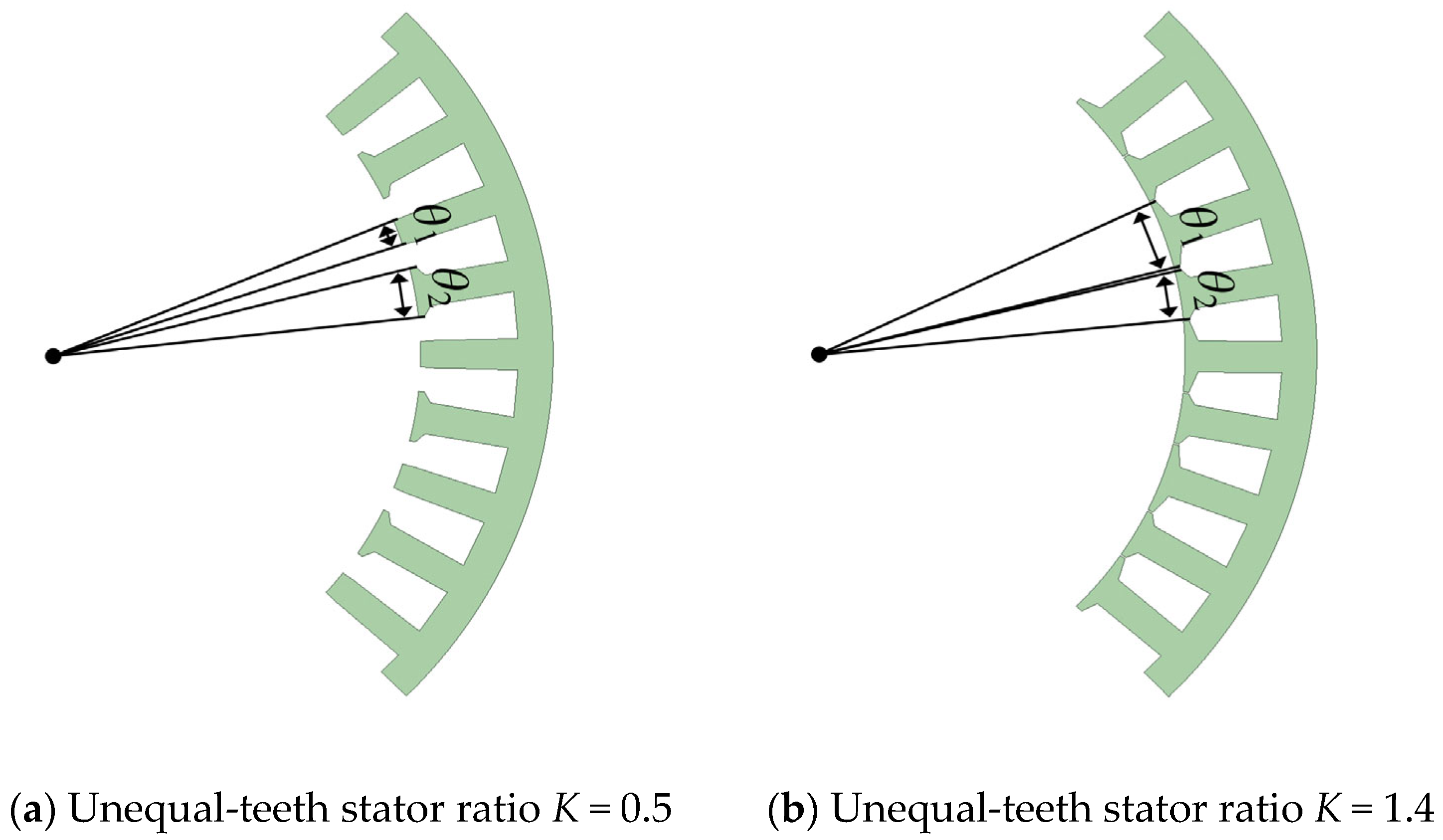
3.1. Design of Unequal-Teeth Stator Structure in FSCW-PMSMs

Based on the principle of the teeth modulation effect, the modulation of high-order radial electromagnetic forces (REFs) is related to the stator teeth. By optimizing the stator teeth, the air-gap flux density can be altered, and the modulation effect of the REFs can be weakened, thus reducing the vibration and noise levels in FSCW-PMSMs.
An unequal-teeth stator structure that reduces vibration and noise is proposed, as shown in Figure 4. Since the stator teeth dimensions of each FSCW-PMSM vary, in order to apply the proposed low-vibration noise-reducing unequal-teeth stator design to different FSCW-PMSMs, θ1 is defined as the mechanical angle occupied by the optimized stator teeth in space, and θ2 as the mechanical angle occupied by the conventional stator teeth. The unequal-teeth stator structure is characterized by the ratio K = θ1/θ2.
This study investigates the relationship between the modulation of the (6, 2f)-order REF and the ratio K, where K is the ratio of the mechanical angles θ1 of the stator teeth, ranging from 0.5 to 1.4. A small value of K increases the air gap length, which negatively impacts the torque output. On the other hand, a large value of K leads to the stator slot opening approaching 0 mm, causing significant magnetic leakage and adversely affecting the machine’s average torque output, as shown in Figure 5.
The teeth width variations in the proposed unequal-teeth stator structure are a result of meticulous optimization, not arbitrary modifications. Modern manufacturing processes, including precision stamping and die making, can implement these specific geometries with controlled impacts on cost and efficiency. While the direct manufacturing cost of the machine might see a slight increase, the unequal-teeth stator structure design offers significant advantages by reducing system vibration and noise. This is achieved by weakening the radial electromagnetic forces—the primary source of machine vibration and noise—thus minimizing the need for expensive external control treatments. Moreover, the pronounced reduction in vibration and noise directly improves long-term operational reliability by lessening wear and fatigue on components like bearings and connectors, and, consequently, reducing maintenance.
Finite element simulations are conducted for FSCW-PMSM with different K values to observe the variation in the modulated (6, 2f)-order REF amplitude under rated operating conditions, as shown in Figure 6. From the trend observed in Figure 6, it can be seen that the amplitude of the modulated (6, 2f)-order REF decreases gradually from K = 0.5 to K = 1.2. However, when K > 1.2, the modulated (6, 2f)-order REF amplitude starts to increase. The unequal-teeth stator structure design with K = 1.2, under rated operating conditions, results in the minimum amplitude of the modulated (6, 2f)-order REF. When K = 1.2, this non-uniform arrangement of stator teeth effectively weakens the amplitude of the low-order radial electromagnetic forces originally generated by the modulation of high-order radial electromagnetic forces through the teeth.
As observed in Figure 7, the impact of the unequal-teeth stator structure on the average torque of the machine is evident. When the ratio K is in the range of 0.5 to 1.0, the average torque of the machine gradually increases, indicating that a moderate increase in K is beneficial for enhancing torque output. However, as K exceeds 1.0, the average torque begins to decrease, suggesting that an excessively large K value adversely affects the average torque, thereby reducing the machine’s torque output capability. When the K value is either too small or too large, it may increase leakage flux or alter the magnetic circuit’s saturation state, thereby affecting the amplitude of the fundamental air-gap flux density and, consequently, impacting the average torque.
Meanwhile, as shown in Figure 8, the unequal-teeth stator structure also has a noticeable impact on the torque ripple characteristics of the machine. As the K value increases from 0.5 to 1.2, the torque ripple gradually decreases, indicating that the unequal-teeth stator structure within this range helps improve torque stability and reduce operational fluctuations. However, when K exceeds 1.2, the torque ripple starts to increase again, suggesting that an excessively large K value may lead to magnetic field imbalances, thereby increasing torque output instability.
To investigate the effect of the unequal-teeth stator structure at different K values on the modulated (6, 2f)-order REF amplitude, the optimal unequal-teeth stator structure is selected. Based on the data from finite element simulations, as shown in Table 3, the unequal-teeth stator structure with K = 1.2 results in the minimum amplitude of the modulated (6, 2f)-order REF, while also achieving relatively high average torque and smaller torque ripple. Therefore, the unequal-teeth stator structure with K = 1.2 is chosen as the optimal solution for reducing vibration and noise in the machine.
Considering manufacturing processes enhances the practical engineering value of this study. Since low-order radial electromagnetic force is the dominant source of vibration and noise in machines, the variation in (6, 2f) radial electromagnetic force amplitude is prioritized when determining the manufacturing tolerance range, alongside the overall electromagnetic performance, as illustrated in Figure 9 and Figure 10, under rated operating conditions. Taking the (6, 2f) radial electromagnetic force amplitude of the unequal-teeth stator structure with K = 1.2 as the reference, the allowable variation in (6, 2f) radial electromagnetic force amplitude is limited to within 5%, and the torque reduction must not exceed 5% of the average torque of the conventional stator structure, as illustrated in Figure 9 and Figure 10. Based on these two criteria, the manufacturing tolerance range for K is determined to be between 1.15 and 1.3, as shown in Table 4.

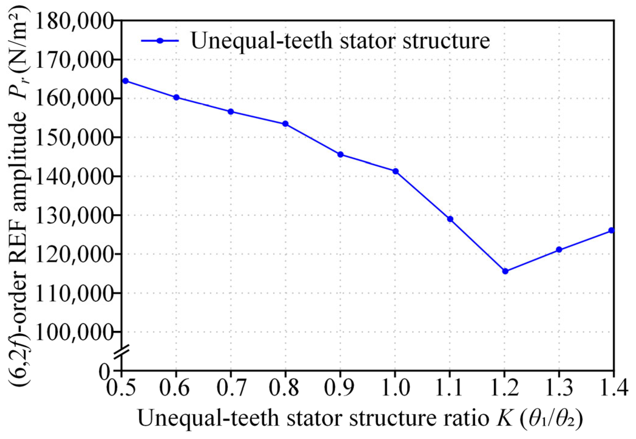
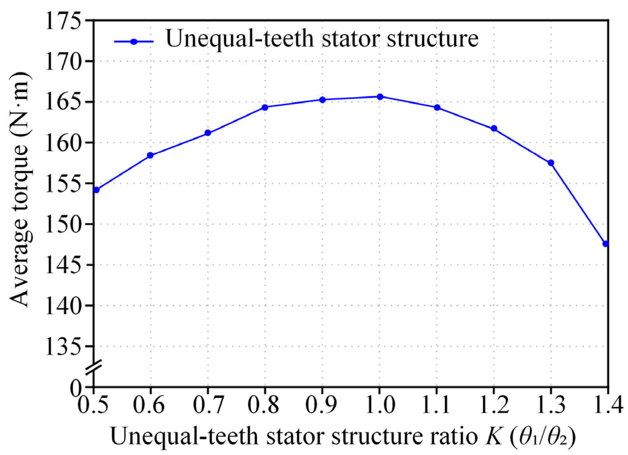
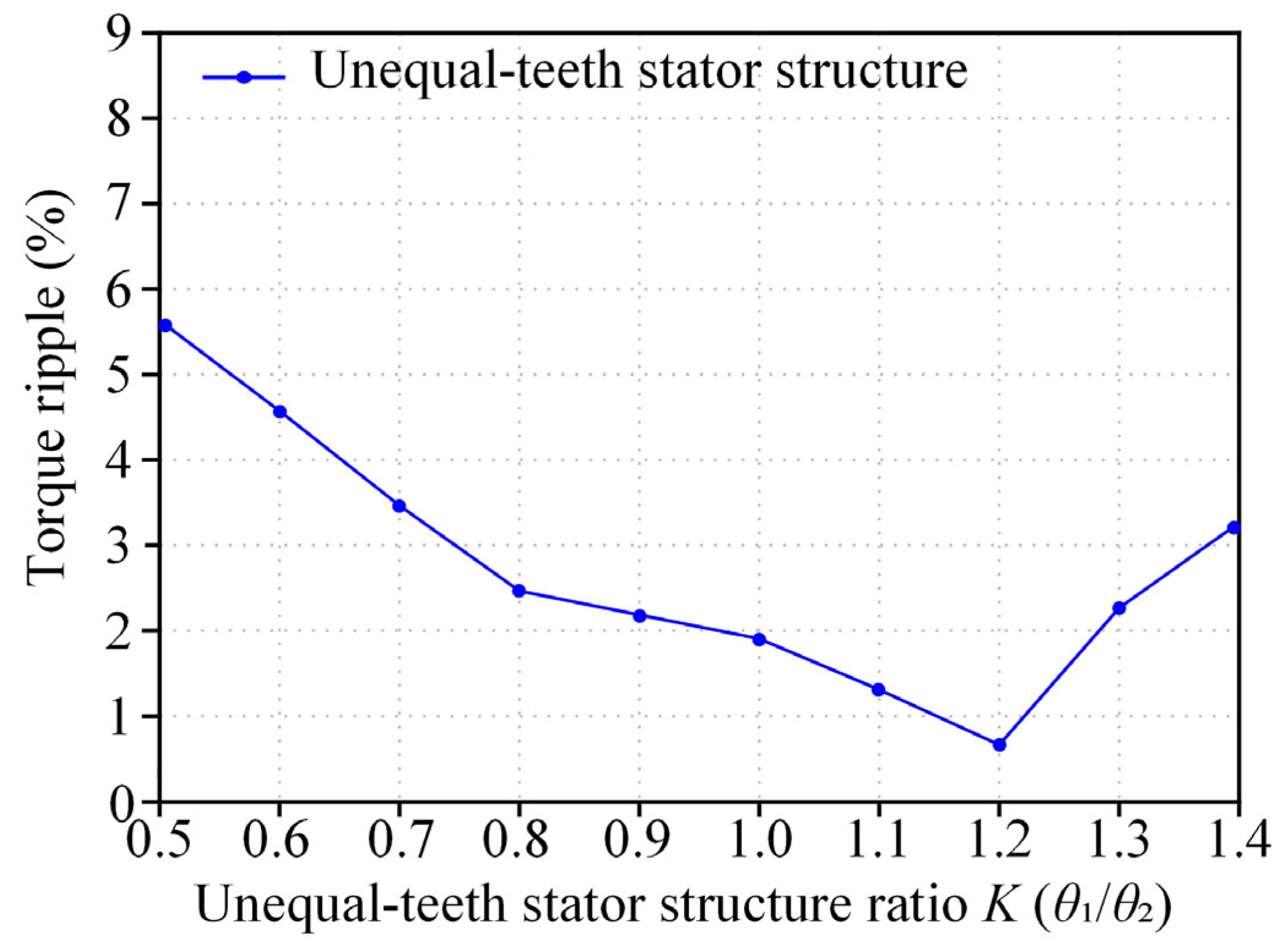
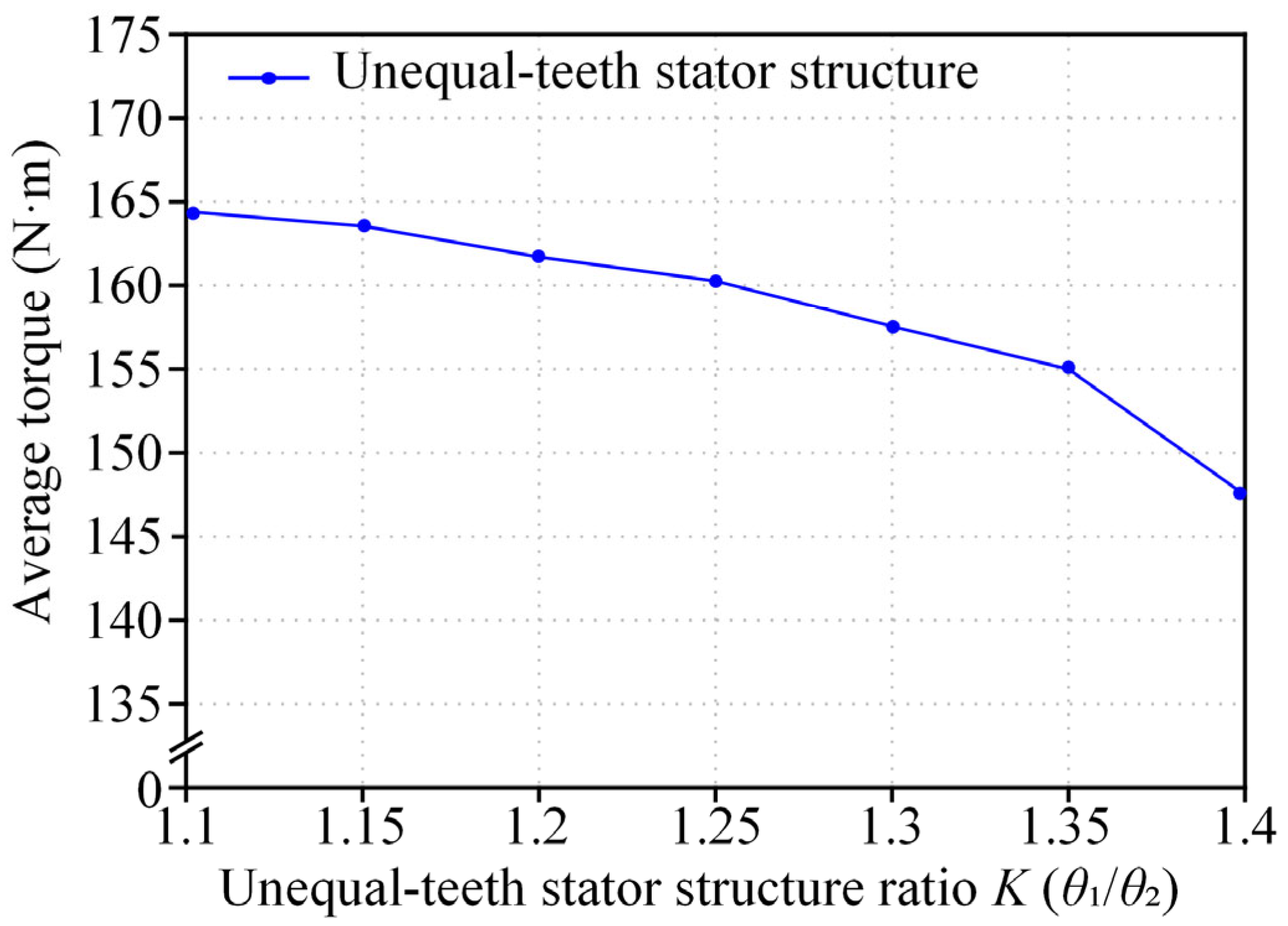
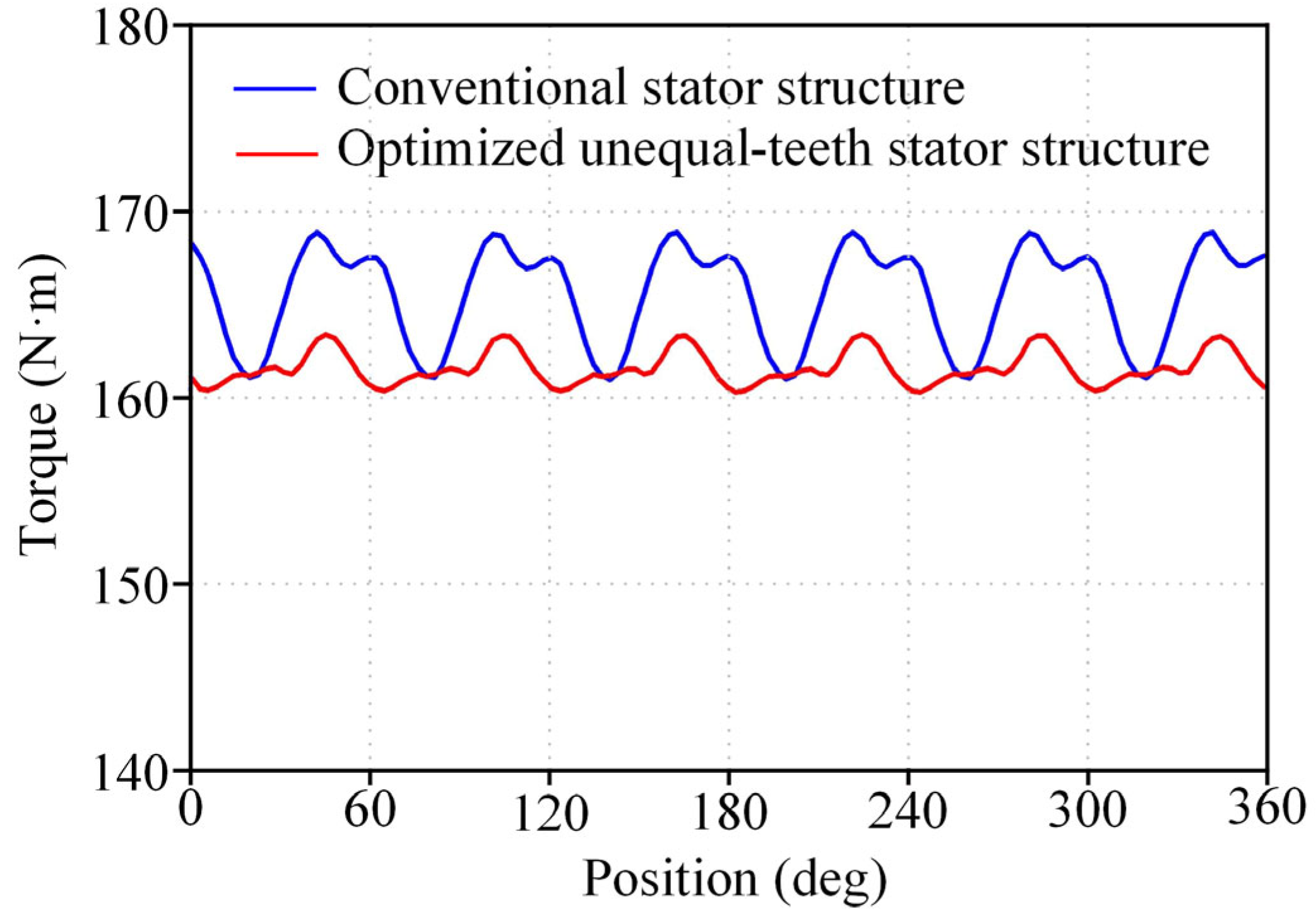
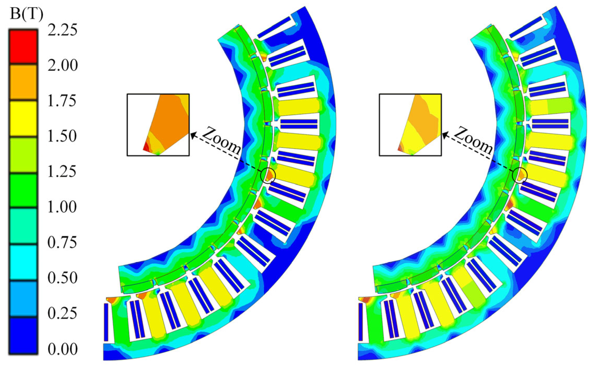
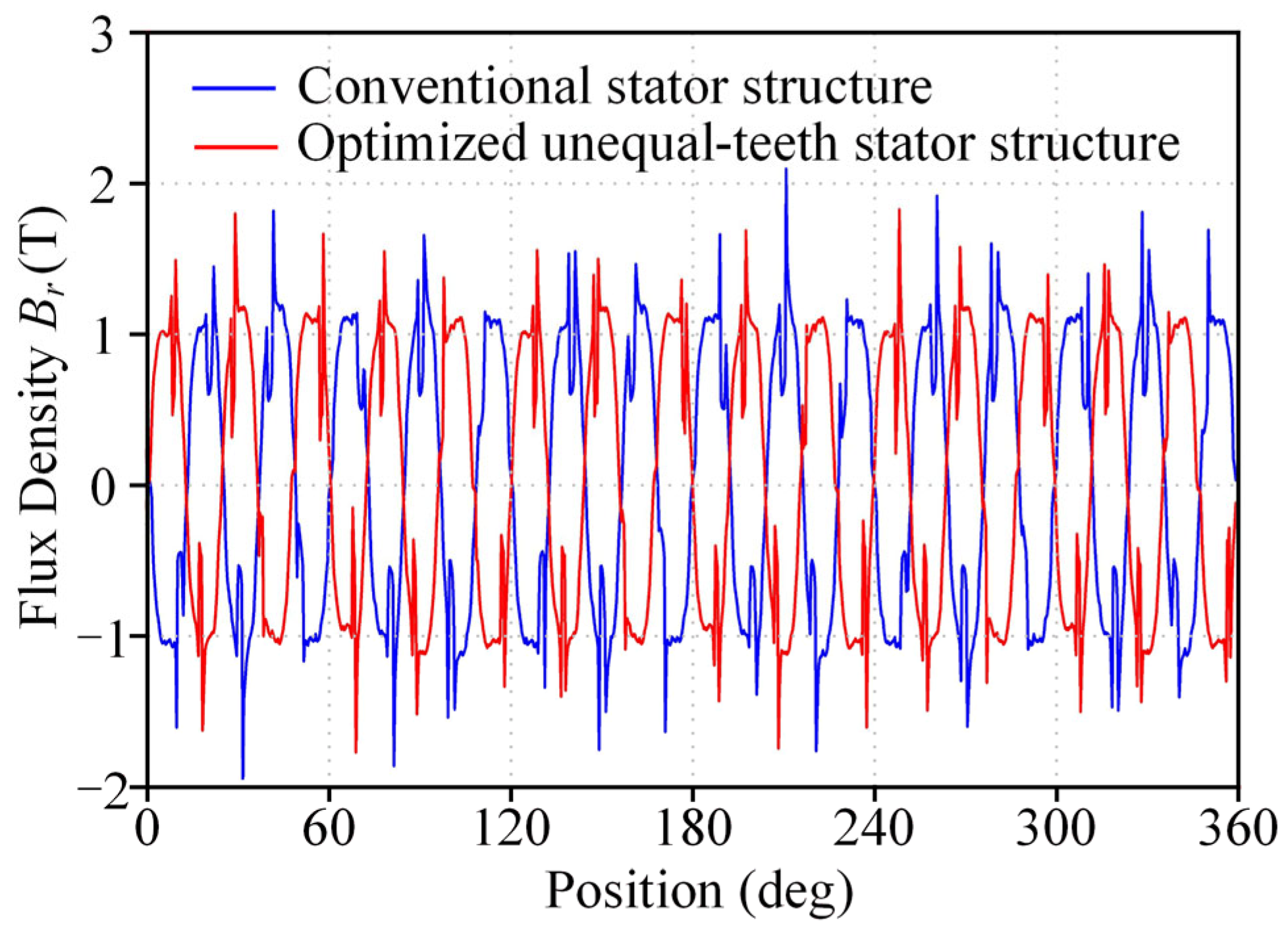
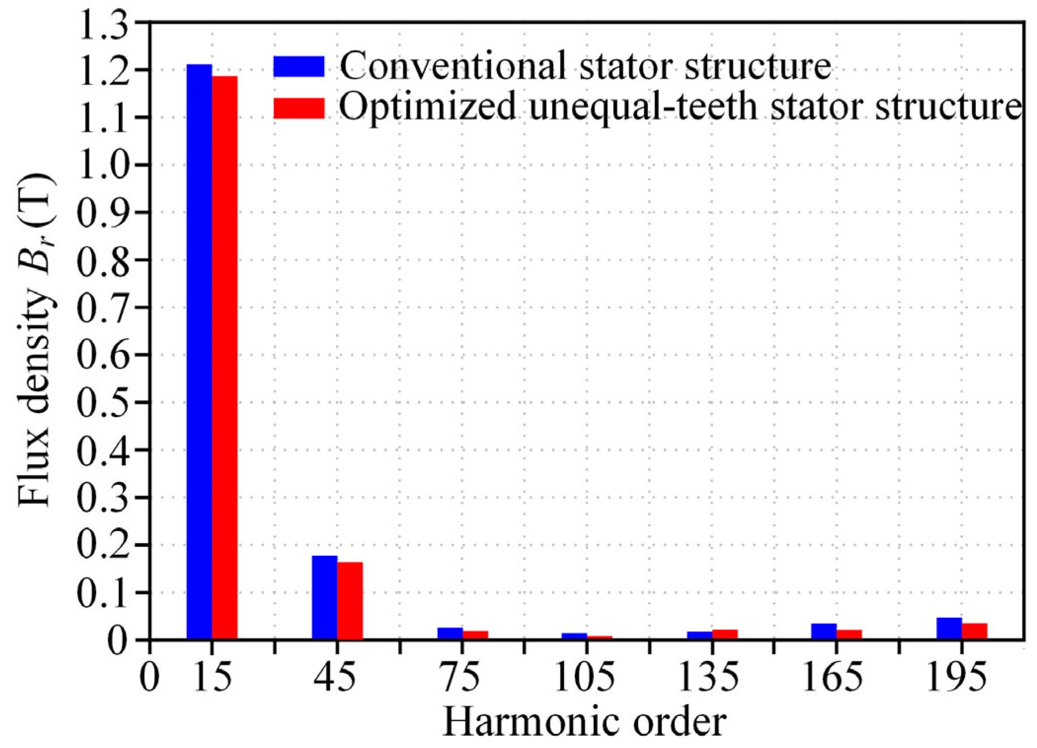
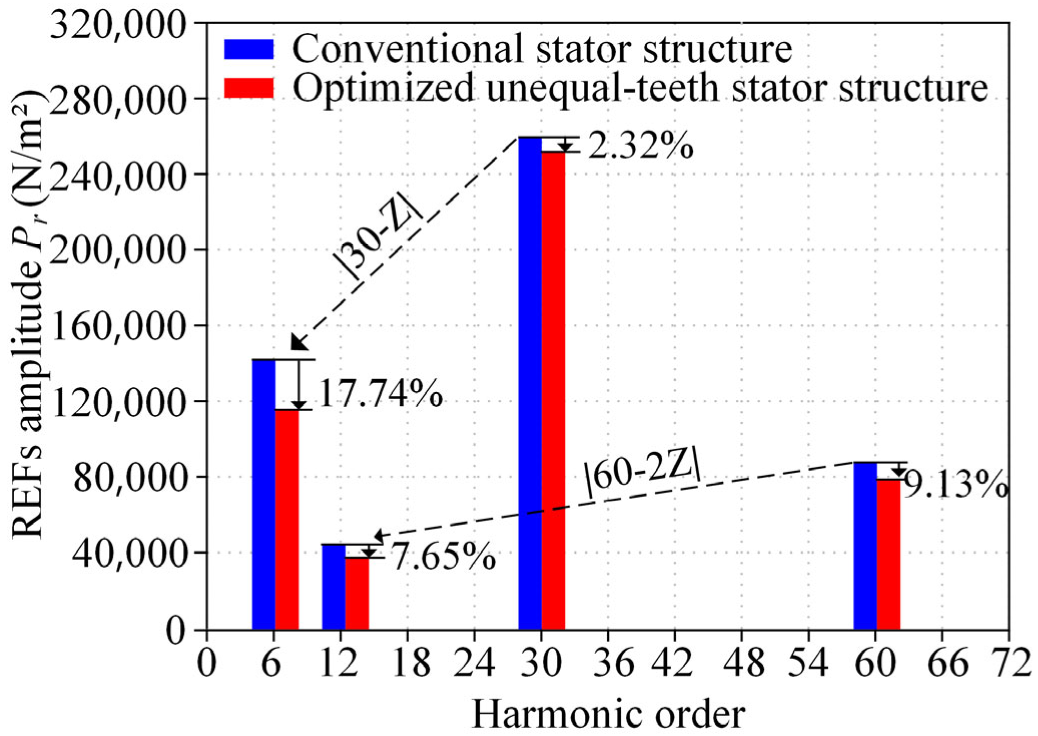
3.2. Electromagnetic Performance Analysis of an FSCW-PMSM with the Optimized Unequal-Teeth Stator Structure Under Rated Operating Conditions

Based on the unequal-teeth stator structure optimization scheme obtained in the previous section (with K = 1.2), this section analyzes the electromagnetic performance of the optimized unequal-teeth stator structure.
The average torque of the conventional stator structure and the optimized unequal-teeth stator structure is shown in Figure 11. The stator slot opening of the optimized unequal-teeth stator structure is reduced, which increases magnetic leakage and leads to a slight decrease in the average electromagnetic torque. Compared to the conventional stator structure, the average torque of the optimized unequal-teeth stator structure is reduced by 3.2 N, corresponding to a decrease of 1.94%. The average torque reduction is within 5%, with a torque ripple of 0.77%, which meets the design requirements of the machine.
Compared to the conventional stator structure, the flux density in the optimized unequal-teeth stator structure is slightly reduced. This is because the stator teeth’s cross-sectional area increases in the machine with the optimized unequal-teeth stator structure, which improves the saturation level at the stator teeth compared to the conventional stator structure. As a result, the flux density decreases to some extent, and therefore, the reduction in average torque is not significant, as shown in Figure 12.
Compared to the conventional stator structure, the radial magnetic flux density amplitude of the optimized unequal-teeth stator structure shows a certain decrease. By performing a Fourier decomposition on the radial magnetic flux density, it is clearly observed that the optimized unequal-teeth stator structure with K = 1.2 weakens the fundamental and third harmonic components of the air-gap radial magnetic flux density. The higher-order harmonics, due to their smaller amplitudes, have a lesser effect on the REFs’ amplitude, as shown in Figure 13 and Figure 14.
Compared to the conventional stator structure, the (30, 2f)-order REF amplitude of the machine with the optimized unequal-teeth stator structure decreases by 2.32%. The (30, 2f)-order REF, modulated by one time the number of stator teeth, results in a 17.74% decrease in the (6, 2f)-order REF amplitude. The (60, 4f)-order REF amplitude decreases by 9.13%, and the (12, 4f)-order REF modulated by two times the number of stator teeth decreases by 7.65%, as shown in Figure 15 and Table 5.
The modulation of high-order radial electromagnetic forces (REFs) into low-order REFs due to the teeth modulation effect is a major cause of elevated vibration and noise in the machine. As REFs are transmitted from the air gap to the stator teeth, high-order components are modulated into low-order components. Since the vibration acceleration of the machine is inversely proportional to the fourth power of the spatial order of the REF, high-order REFs are neglected, and the focus is placed on the impact of low-order REFs on vibration and noise.

4. Modal and Vibration Noise Analysis of the Machine with Optimized Unequal-Teeth Stator Structure

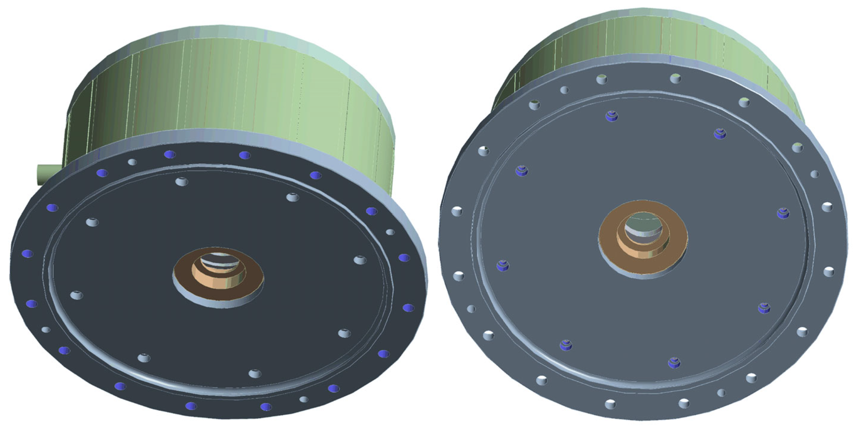
4.1. Boundary Conditions Setup for Finite Element Simulation

To analyze the vibration and noise characteristics of the machine with the optimized unequal-teeth stator structure, a coupled simulation using Maxwell (2021) and Workbench (2021) is conducted. The simulation procedure for vibration and noise analysis is illustrated in Figure 16. Firstly, the radial electromagnetic forces (REFs) calculated in Maxwell are imported as an excitation into the Harmonic Response module for further analysis. Material properties are assigned to the stator and housing of the machine, and the machine’s fixed constraints under actual operating conditions are simulated to calculate the vibration response on the surface of the machine housing. Subsequently, a cylindrical acoustic domain with a radius of 1 m (air medium) is established. The vibration response on the machine housing surface is then used as the excitation input for the Harmonic Acoustics module to compute the radiated noise from the housing surface.
A 3D finite element model is established, as shown in Figure 17. The 3D model of the machine includes detailed components such as the upper end cap, lower end cap, housing, flange, and stator core. The materials and their properties for each component are listed in Table 6.
The boundary conditions for the finite element simulation of machine vibration and noise mainly include: the fixed connection between the machine flange and the dynamometer; the fixation between the lower end cap and the machine flange; and the bonded contact between the stator core and the housing, ensuring no relative motion between them, as illustrated in Figure 18 and Figure 19.
Subsequently, a 3D acoustic domain model is established, with the outermost surface of the acoustic domain set as a radiation boundary. This allows sound waves to propagate outward without reflection, enabling accurate analysis of sound radiation characteristics within a limited computational domain, as illustrated in Figure 20.
The upper and lower end caps of both stator structures are meshed with tetrahedral elements sized at 10 mm; the housing is meshed with tetrahedral elements sized at 8 mm; the flange is meshed with tetrahedral elements sized at 15 mm; and the stator core is meshed with multizone elements sized at 4 mm. Meanwhile, the stator teeth surfaces subjected to radial electromagnetic forces are refined with a mesh size of 2 mm. The average mesh quality exceeds 0.7, ensuring good simulation accuracy, as shown in Table 7 and Table 8.

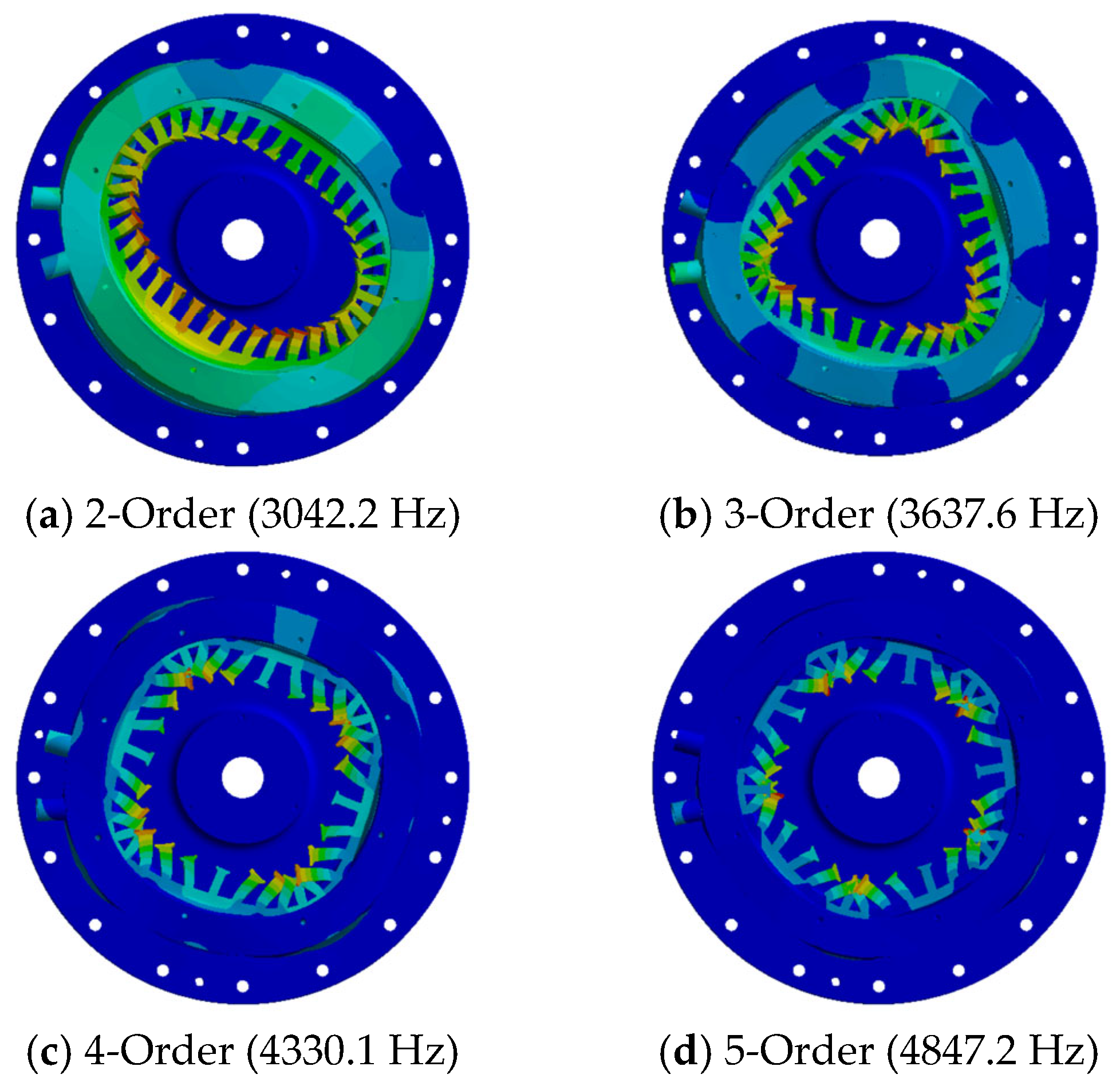
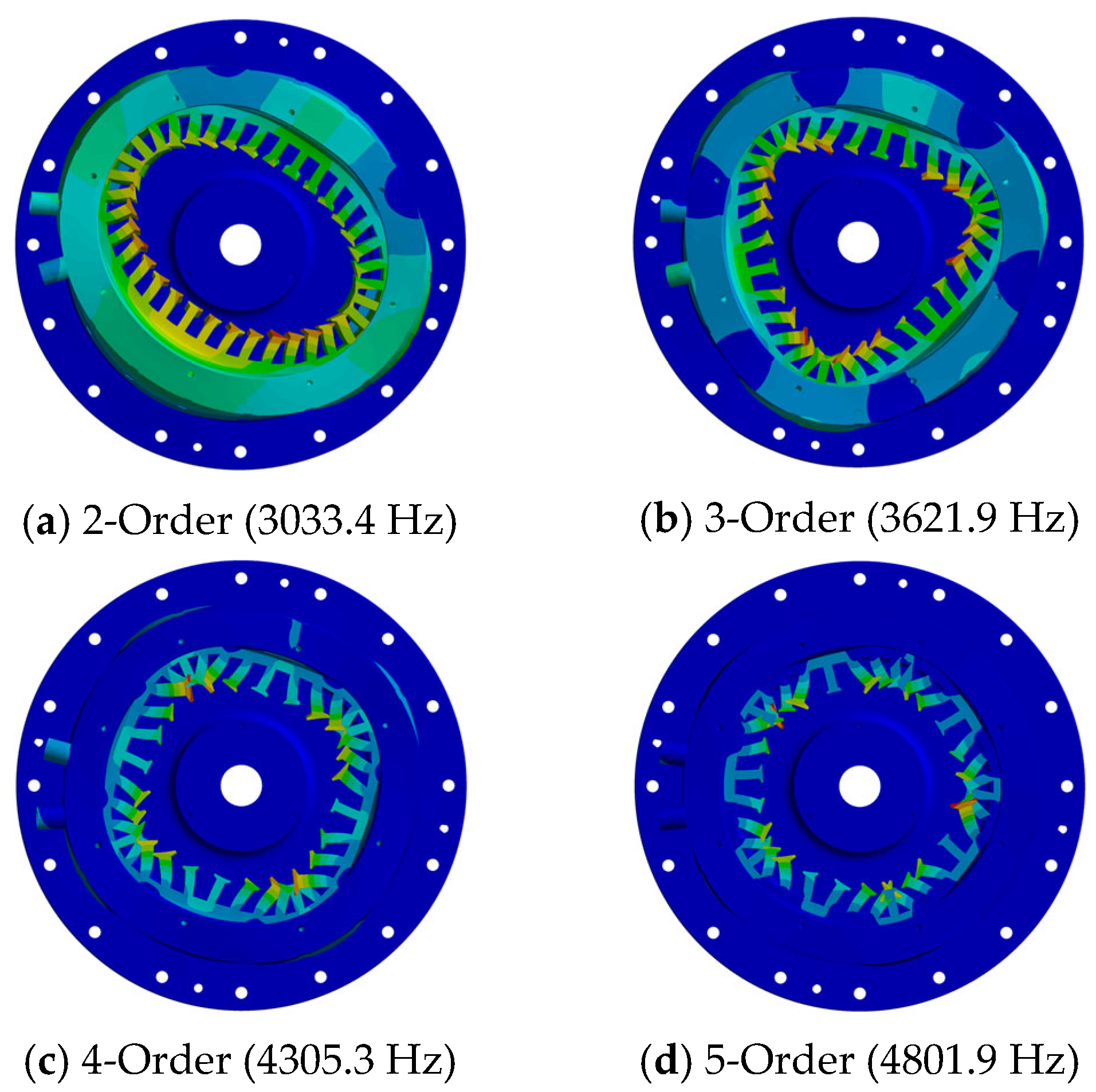
4.2. Modal Analysis of the Optimized Unequal-Teeth Stator Structure

Modal analysis of permanent magnet machines serves as a preliminary approach for evaluating vibration behavior, enabling the identification of structural resonance. When the spatial order and frequency of the radial electromagnetic forces in a permanent magnet synchronous machine are close to coinciding with the modal order and natural frequency of the machine structure, resonance may occur, resulting in significant vibration and noise. With the structural modification introduced by the optimized unequal-teeth stator design, the modal characteristics of the machine are also altered. To avoid resonance, it is essential to accurately determine the vibration modes and corresponding natural frequencies.
Conventional analytical methods typically approximate the stator core as a slotted, hollow cylindrical structure; however, due to the complexity of the actual stator geometry and the difficulty in applying realistic boundary conditions, such methods have limited accuracy. Therefore, this study employs a finite element simulation approach to analyze and compare the modal characteristics of both the conventional stator structure and the optimized unequal-teeth stator structure.
Through modal analysis of the optimized unequal-teeth stator structure, the mode shapes and natural frequencies of both the conventional stator structure and the optimized design are obtained, as illustrated in Figure 21 and Figure 22.
The results indicate that, for both structures, the modal shapes and frequencies differ significantly from the spatial orders and frequencies of the REFs, and thus resonance does not occur. Based on this analysis, the design of the unequal-teeth stator structure with K = 1.2 is deemed reasonable, as it not only meets the performance requirements of the machine but also prevents resonance, thereby ensuring stable operation.

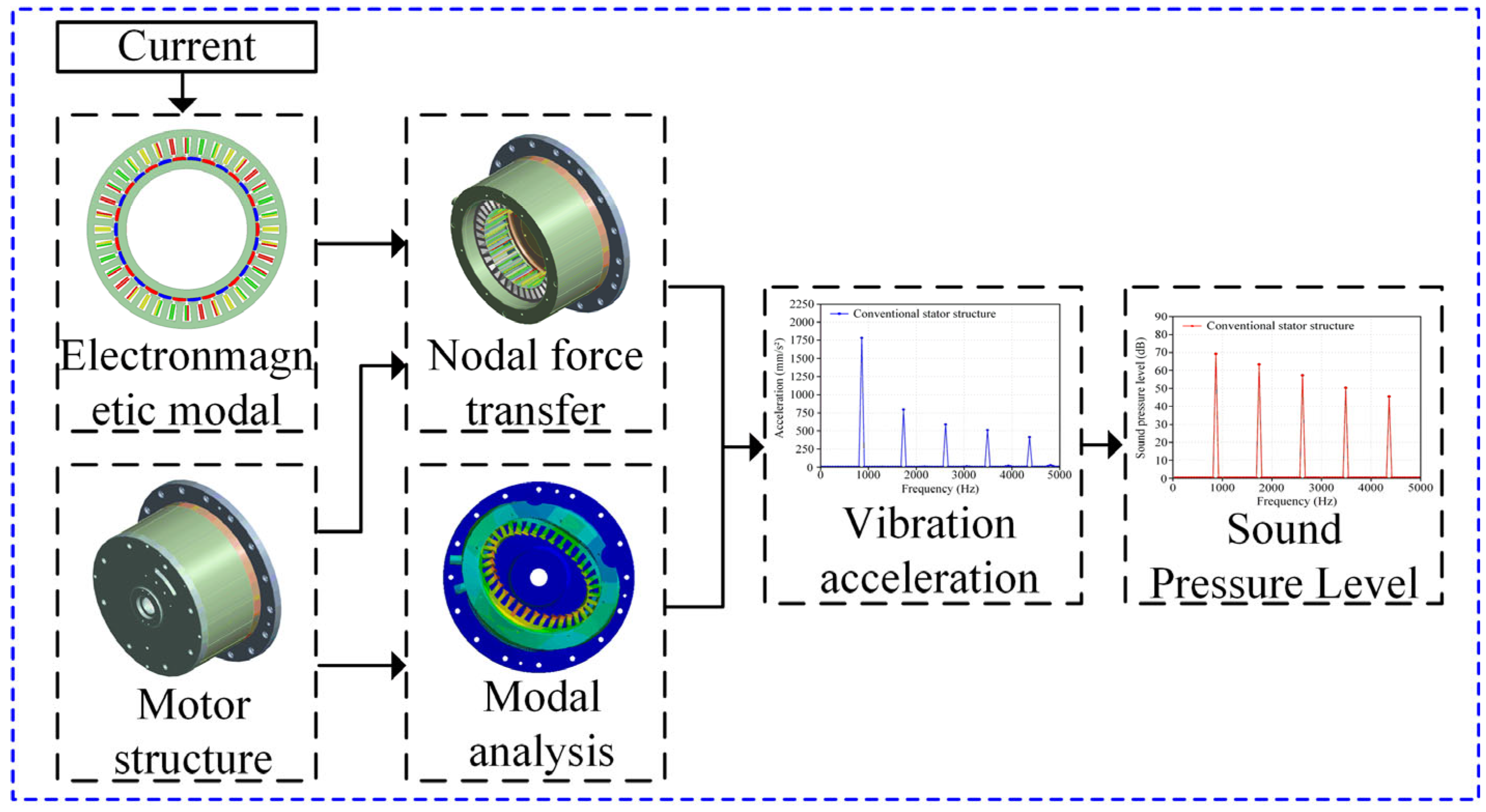
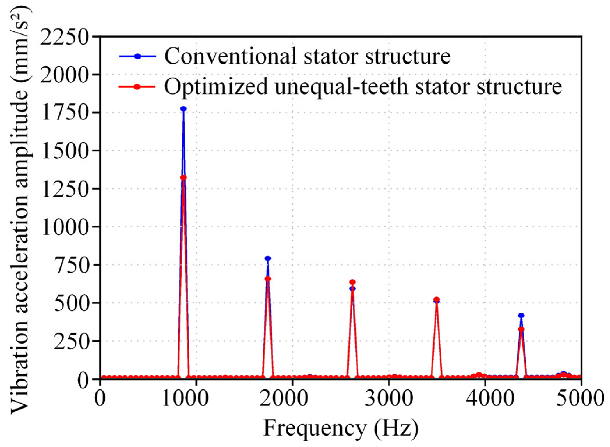
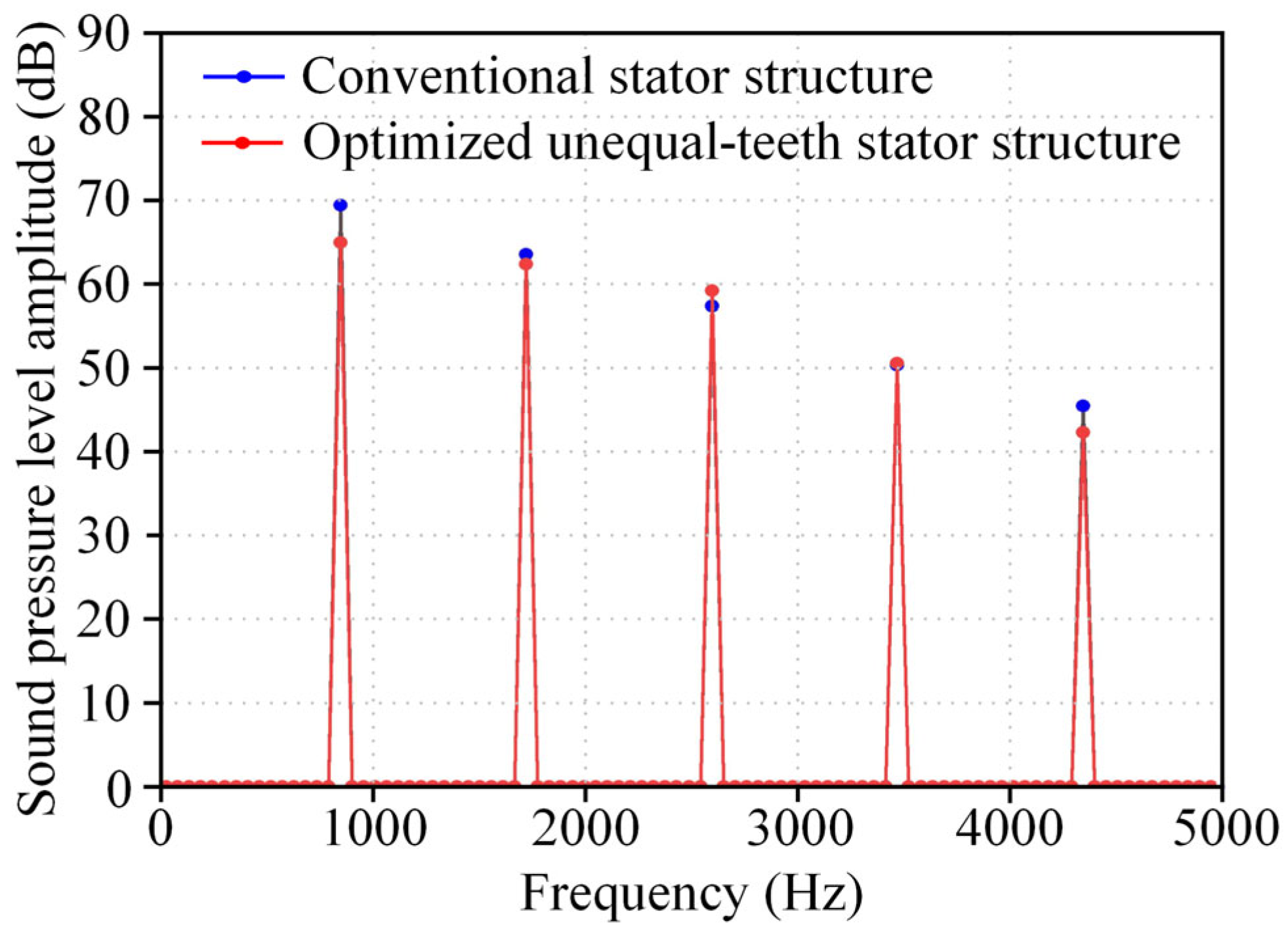
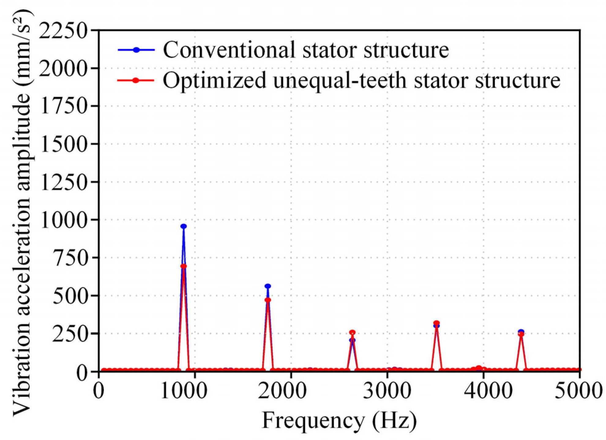
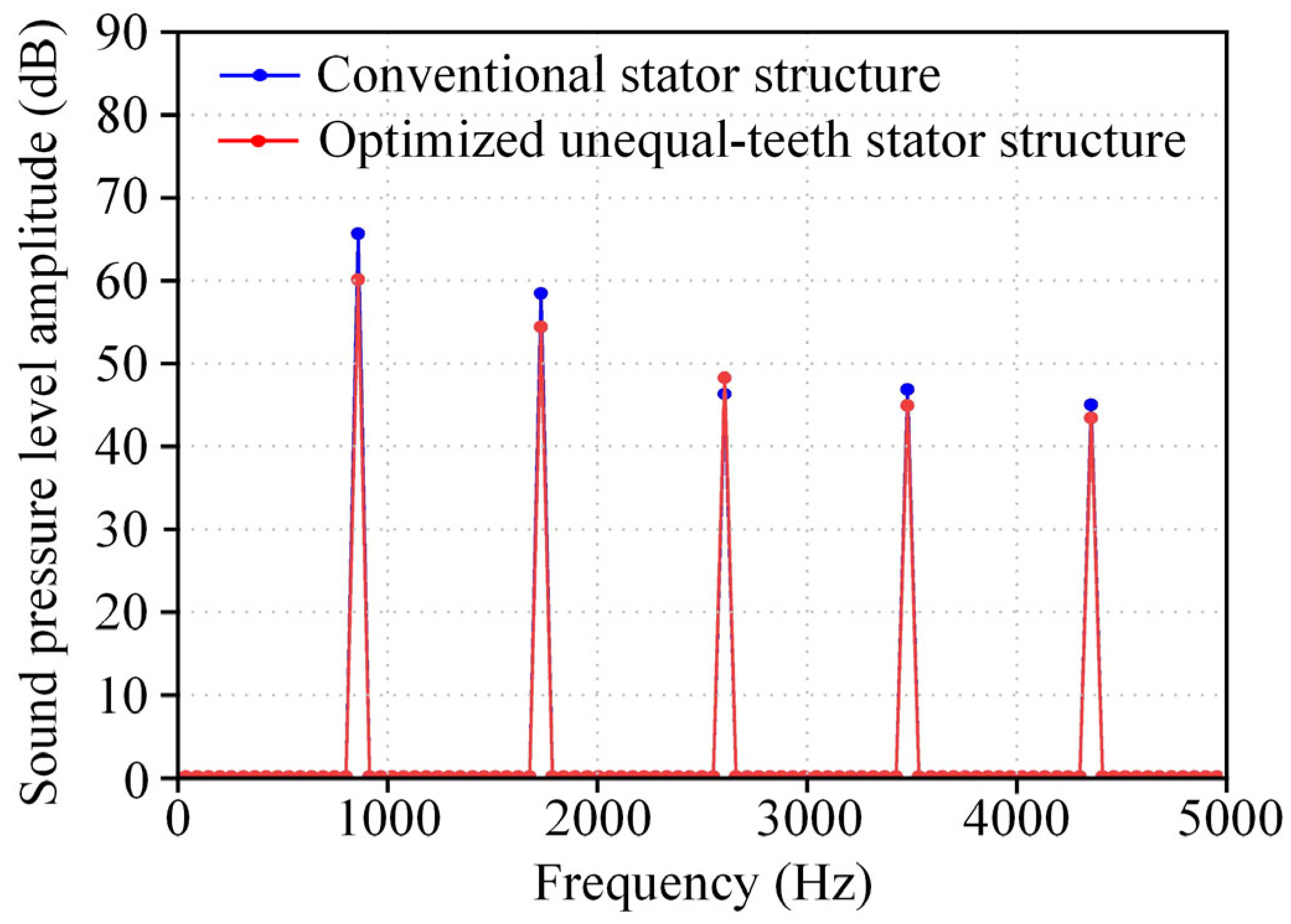
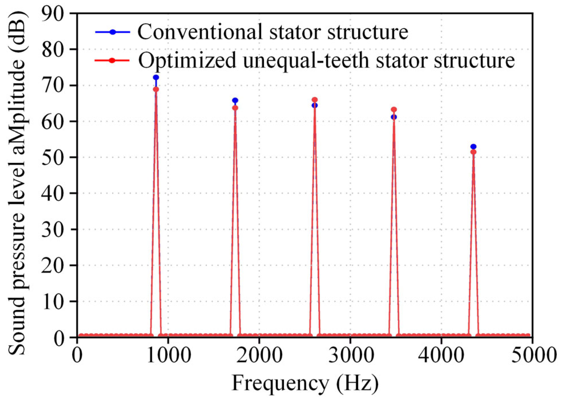
4.3. Vibration and Noise Analysis of the Optimized Unequal-Teeth Stator Structure

Through finite element harmonic response analysis of the machine vibrations, it is observed that the radial electromagnetic force (REF) at 2f results in a deformation with a 6-order mode shape, as shown in Figure 23. This verifies that the (30, 2f)-order REF of the machine, after modulation by the stator teeth, generates a (6, 2f)-order REF, which plays a decisive role in the vibration and noise of the machine.
The machine vibration and noise performance are analyzed under rated operating conditions at a speed of 1750 rpm and a load torque of 165 N·m. The vibration acceleration spectrum curves for both the conventional stator structure and the optimized unequal-teeth stator structure are calculated under rated operating conditions. At 2f, the vibration acceleration of the optimized unequal-teeth stator structure decreases by 447.70 mm/s2, as shown in Figure 24.
Further calculations of the electromagnetic noise sound pressure level (SPL) radiated from the machine housing surface under rated operating conditions show that the optimized unequal-teeth stator structure results in a 4.49 dB reduction in SPL at 2f compared with the conventional stator structure, as illustrated in Figure 25.
Under rated operating conditions, the vibration and noise performance improvements of the optimized unequal-teeth stator structure compared with the conventional stator structure, along with detailed numerical results, are presented in Table 9.
The machine vibration and noise performance is given under no-load conditions at a speed of 1750 rpm.
The vibration acceleration spectrum curves for both the conventional stator structure and the optimized unequal-teeth stator structure are calculated under no-load operating conditions. The vibration acceleration of the optimized unequal-teeth stator structure decreases by 267.39 mm/s2 at 2f, as shown in Figure 26.
Further calculations of the electromagnetic noise sound pressure level (SPL) radiating from the machine housing surface under no-load operating conditions show that, compared with the conventional stator structure, the optimized unequal-teeth stator structure results in a 5.58 dB reduction in SPL at 2f, as illustrated in Figure 27.
Under no-load operating conditions, the vibration and noise performance improvements of the optimized unequal-teeth stator structure compared with the conventional stator structure, along with detailed numerical results, are presented in Table 10.
The machine vibration and noise performance are taken under peak torque conditions at a speed of 1750 rpm and a load torque of 360 N·m. The vibration acceleration spectrum curves for both the conventional stator structure and the optimized unequal-teeth stator structure are calculated under peak torque operating conditions. The vibration acceleration of the optimized unequal-teeth stator structure decreases at 2f by 579.76 mm/s2, as shown in Figure 28.
Further calculations of the electromagnetic noise sound pressure level (SPL) radiating from the machine housing surface under peak torque operating conditions show that the optimized unequal-teeth stator structure reduces the SPL at 2f by 3.44 dB compared with the conventional stator structure, as illustrated in Figure 29.
Under peak torque operating conditions, the vibration and noise performance improvements of the optimized unequal-teeth stator structure compared with the conventional stator structure, along with detailed numerical results, are presented in Table 11.
The above results indicate that the optimized unequal-teeth stator structure effectively mitigates the vibration and noise of the machine, improving its overall vibration and acoustic performance. The reduction in vibration noise at 2f in the machine with the optimized unequal-teeth stator structure can be attributed to two main factors: first, the optimized structure alters the air-gap flux density amplitude, leading to a decrease in the (30, 2f)-order REF amplitude; second, it weakens the amplitude of the modulated (6, 2f)-order REF. These two effects work together to reduce the vibration and noise of the machine.

5. Conclusions

To address the issue of high vibration and noise in FSCW-PMSMs due to teeth modulation effects, this paper investigates the impact of teeth modulation on radial electromagnetic forces (REFs). Finite element simulations are conducted to validate the effect of teeth modulation on machine vibration noise. A novel low-vibration noise unequal-teeth stator structure design method is proposed, where the optimal ratio (K value) of adjacent unequal-teeth stator structures is selected to weaken the teeth modulation effect, thereby reducing machine vibration noise. The results show the following:
  • This paper proposes a novel low-vibration noise stator structure design methodology. To address variations in machine dimensions, a relative ratio parameter K for the unequal-teeth stator structure is introduced. Finite element simulations are employed to investigate how different stator tooth ratios affect the amplitude of modulated low-order radial electromagnetic forces. By selecting an appropriate unequal-teeth stator ratio, the vibration and noise of the machine can be effectively reduced, demonstrating the potential for broader application in other fractional-slot permanent magnet synchronous machines.
  • The proposed method is evaluated under rated, no-load, and peak torque operating conditions. The optimized unequal-teeth stator structure shows a significant reduction in vibration and noise performance. Compared to the conventional stator structure, the optimized unequal-teeth stator structure reduces vibration acceleration by 25.53% and sound pressure level by 6.44% under rated conditions; by 27.88% and 8.50%, respectively, under no-load conditions; and by 21.77% and 4.74%, respectively, under peak torque conditions.
The finite element simulation analysis presented in this paper offers encouraging initial evidence that the proposed unequal-teeth stator structure can effectively mitigate vibration and noise by suppressing the teeth modulation effect. Despite the promising results, the current study lacks a comprehensive analytical model to quantitatively elucidate how the unequal-teeth stator structure influences teeth modulation effects, accurately predict the variations in high-order radial electromagnetic forces under different K values, and explain how these variations contribute to the suppression of low-order radial electromagnetic forces. Developing such a model remains a critical direction for future research. Meanwhile, subsequent work will focus on the fabrication of prototypes for both the conventional and optimized unequal-teeth stator structures, accompanied by thorough experimental investigations into their vibration and noise characteristics, with consideration of factors such as temperature fluctuations, manufacturing tolerances, and vibration and noise behavior across the full speed range, as well as simulation uncertainties and confidence intervals, to better simulate actual working conditions.

Author Contributions

Conceptualization, L.G.; methodology, L.G., X.L., H.Z., and T.Z.; software, H.Z.; validation, H.Z. and X.L.; formal analysis, H.Z. and T.Z.; investigation, X.L., H.Z., L.G., and H.W.; resources, L.G.; data curation, H.W.; writing—original draft, H.Z.; writing—review and editing, X.L., H.Z., L.G., and T.Z.; visualization, L.G.; supervision, L.G.; project administration, Z.L.; funding acquisition, L.G. All authors have read and agreed to the published version of the manuscript.

Funding

This work was supported by the National Key R&D Program of China (2023YFB2504300), and we greatly appreciate the support from the Program.

Data Availability Statement

The data presented in this study are available in the article.

Conflicts of Interest

Author T.Z. is employed by Vitesco Technologies. The authors declare no conflicts of interest.

References

  1. Zakri, K.W.; Sarwono, R.S.J.; Santosa, S.P.; Soelami, F.X.N. Modeling and Validation of Acoustic Comfort for Electric Vehicle Using Hybrid Approach Based on Soundscape and Psychoacoustic Methods. World Electr. Veh. J. 2025, 16, 64. [Google Scholar] [CrossRef]
  2. Dong, J.; Yin, H.; Li, G.; Wang, X.; Luo, M. The Multiphysics Analysis and Suppression Method for the Electromagnetic Noise of Permanent-Magnet Motors Used in Electric Vehicle. World Electr. Veh. J. 2025, 16, 136. [Google Scholar] [CrossRef]
  3. Wang, J.; Patel, V.I.; Wang, W. Fractional-Slot Permanent Magnet Brushless Machines with Low Space Harmonic Contents. IEEE Trans. Magn. 2013, 50, 1–9. [Google Scholar] [CrossRef]
  4. Fang, Y.; Zhang, T. Vibroacoustic Characterization of a Permanent Magnet Synchronous Motor Powertrain for Electric Vehicles. IEEE Trans. Energy Convers. 2017, 33, 272–280. [Google Scholar] [CrossRef]
  5. Zhu, Z.Q.; Howe, D.; Bolte, E.; Ackermann, B. Instantaneous magnetic field distribution in brushless permanent magnet DC motors. I. Open-circuit field. IEEE Trans. Magn. 1993, 29, 124–135. [Google Scholar] [CrossRef]
  6. Zhu, Z.; Howe, D. Instantaneous magnetic field distribution in brushless permanent magnet DC motors. II. Armature-reaction field. IEEE Trans. Magn. 1993, 29, 136–142. [Google Scholar] [CrossRef]
  7. Zhu, Z.; Howe, D. Instantaneous magnetic field distribution in brushless permanent magnet DC motors. III. Effect of stator slotting. IEEE Trans. Magn. 1993, 29, 143–151. [Google Scholar] [CrossRef]
  8. Zhu, Z.; Howe, D. Instantaneous magnetic field distribution in permanent magnet brushless DC motors. IV. Magnetic field on load. IEEE Trans. Magn. 1993, 29, 152–158. [Google Scholar] [CrossRef]
  9. Yang, H.; Chen, Y. Influence of Radial Force Harmonics With Low Mode Number on Electromagnetic Vibration of PMSM. IEEE Trans. Energy Convers. 2013, 29, 38–45. [Google Scholar] [CrossRef]
  10. Zhu, Z.Q.; Xia, Z.P.; Wu, L.J.; Jewell, G.W. Analytical Modeling and Finite-Element Computation of Radial Vibration Force in Fractional-Slot Permanent-Magnet Brushless Machines. IEEE Trans. Ind. Appl. 2010, 46, 1908–1918. [Google Scholar] [CrossRef]
  11. Dajaku, G.; Xie, W.; Gerling, D. Reduction of Low Space Harmonics for the Fractional Slot Concentrated Windings Using a Novel Stator Design. IEEE Trans. Magn. 2013, 50, 1–12. [Google Scholar] [CrossRef]
  12. Zhu, X.; Lee, C.H.T.; Chan, C.C.; Xu, L.; Zhao, W. Overview of Flux-Modulation Machines Based on Flux-Modulation Principle: Topology, Theory, and Development Prospects. IEEE Trans. Transp. Electrif. 2020, 6, 612–624. [Google Scholar] [CrossRef]
  13. Bertoncello, T.; Franceschini, G.; Raghuraman, B.; Diana, M.; Lidbeck, A. Unsymmetrical Pole Design vs Skewing for improving NVH Characteristics and Performance of High Speed PMSM Electric Machines. In Proceedings of the IECON 2022—48th Annual Conference of the IEEE Industrial Electronics Society, Brussels, Belgium, 17–20 October 2022; pp. 1–6. [Google Scholar]
  14. Ciceo, S.; Raia, R.; Paduraru, F.; Sugiura, K. Fast and Accurate Radial-Flux PMSM Step-Skewing Computation Methodology for NVH Improvements Across the Machine Full Operation Range. In Proceedings of the 2024 27th International Conference on Electrical Machines and Systems (ICEMS), Fukuoka, Japan, 26–29 November 2024; pp. 1–6. [Google Scholar]
  15. Soresini, F.; Barri, D.; Ballo, F.; Gobbi, M. Numerical modeling of PMSM noise reduction by harmonic current injection. IEEE Access 2025, 13, 60245–60257. [Google Scholar] [CrossRef]
  16. Ren, M.; Xie, X.; Huang, Z.; Zhang, Z. Novel rubber-electromagnetic composite active/passive vibration isolator. J. Vib. Shock 2021, 40, 32–37. [Google Scholar]
  17. Wang, R.; Jiang, Y.; Ding, R.; Liu, W.; Meng, X.; Sun, Z. Design and experimental verification of self-powered electromagnetic vibration suppression and absorption system for in-wheel motor electric vehicles. J. Vib. Control 2021, 28, 2544–2555. [Google Scholar] [CrossRef]
  18. Li, Y.; Su, Z. Active vibration reduction technology of marine motor based on sliding-electromagnetic composite bearing. Ship Sci. Technol. 2023, 45, 114–119. [Google Scholar] [CrossRef]
  19. Hong, J.; Wang, S.; Sun, Y.; Sun, X.; Cao, H. The Influence of High-Order Force on Electromagnetic Vibration of Permanent Magnet Synchronous Motors. Trans. China Electrotech. Soc. 2022, 37, 2446–2458. [Google Scholar]
  20. Fang, H.; Li, D.; Qu, R.; Yan, P. Modulation Effect of Slotted Structure on Vibration Response in Electrical Machines. IEEE Trans. Ind. Electron. 2018, 66, 2998–3007. [Google Scholar] [CrossRef]
  21. Liang, W.; Wang, J.; Luk, P.C.-K.; Fei, W. Analytical Study of Stator Tooth Modulation on Electromagnetic Radial Force in Permanent Magnet Synchronous Machines. IEEE Trans. Ind. Electron. 2020, 68, 11731–11739. [Google Scholar] [CrossRef]
  22. Pile, R.; Le Menach, Y.; Le Besnerais, J.; Parent, G. Study of the Combined Effects of the Air-Gap Transfer for Maxwell Tensor and the Tooth Mechanical Modulation in Electrical Machines. IEEE Trans. Magn. 2019, 56, 1–4. [Google Scholar] [CrossRef]
  23. Wang, S.; Hong, J.; Sun, Y.; Cao, H. Analysis of Zeroth-Mode Slot Frequency Vibration of Integer Slot Permanent-Magnet Synchronous Motors. IEEE Trans. Ind. Electron. 2019, 67, 2954–2964. [Google Scholar] [CrossRef]
  24. Wang, S.; Hong, J.; Sun, Y.; Cao, H. Mechanical and Magnetic Pivot Roles of Tooth in Vibration of Electrical Machines. IEEE Trans. Energy Convers. 2020, 36, 139–148. [Google Scholar] [CrossRef]
  25. Zhu, S.; Zhao, W.; Ji, J.; Liu, G.; Lee, C.H.T. Design to reduce electromagnetic vibration in integral-slot SPM machine considering force modulation effect. Sci. China Technol. Sci. 2022, 65, 1867–1877. [Google Scholar] [CrossRef]
  26. Zhu, S.; Zhao, W.; Ji, J.; Liu, G.; Mao, Y.; Liu, T. Investigation of Bread-Loaf Magnet on Vibration Performance in FSCW PMSM Considering Force Modulation Effect. IEEE Trans. Transp. Electrif. 2020, 7, 1379–1389. [Google Scholar] [CrossRef]
  27. Wang, K.; Guo, Y.; Sun, H.; Zhu, S.; Liu, C. Mitigation of Radial Force for Permanent Magnet Machines With Shifted Notch on Stator Teeth. IEEE Trans. Energy Convers. 2023, 39, 1121–1131. [Google Scholar] [CrossRef]
Figure 1. Teeth modulation effect.
Wevj 16 00339 g001
Figure 2. Finite element modeling of the machine.
Wevj 16 00339 g002
Figure 3. Detailed parameters of the machine permanent magnet and stator.
Wevj 16 00339 g003
Figure 4. Schematic diagram of variables for low-vibration noise unequal-teeth design.
Wevj 16 00339 g004
Figure 5. Design of low-vibration noise unequal-teeth stator structure for (a) K = 0.5 and (b) K = 1.4.
Wevj 16 00339 g005
Figure 6. Variation in (6, 2f)-order REF amplitude under unequal-teeth stator structure with K value.
Wevj 16 00339 g006
Figure 7. Variation in average torque under unequal-teeth stator structure with K value.
Wevj 16 00339 g007
Figure 8. Variation in torque ripple under unequal-teeth stator structure with K value.
Wevj 16 00339 g008
Figure 9. Variation in (6, 2f)-order REF amplitude under unequal-teeth stator structure with K value (machine manufacturing tolerance).
Wevj 16 00339 g009
Figure 10. Variation in average torque under unequal-teeth stator structure with K value (machine manufacturing tolerance).
Wevj 16 00339 g010
Figure 11. Torque comparison between the conventional stator structure and the optimized unequal-teeth stator structure.
Wevj 16 00339 g011
Figure 12. Comparison of flux density cloud diagrams between the conventional stator structure and the optimized unequal-teeth stator structure.
Wevj 16 00339 g012
Figure 13. Comparison of radial magnetic flux density between the conventional stator structure and the optimized unequal-teeth stator structure.
Wevj 16 00339 g013
Figure 14. Comparison of radial magnetic flux density Fourier decomposition harmonic amplitude between the conventional stator structure and the optimized unequal-teeth stator structure.
Wevj 16 00339 g014
Figure 15. Comparison of REFs’ amplitude between the conventional stator structure and the optimized unequal-teeth stator structure.
Wevj 16 00339 g015
Figure 16. Finite element simulation procedure for machine vibration and noise.
Wevj 16 00339 g016
Figure 17. The 3D finite element model of the machine stator system.
Wevj 16 00339 g017
Figure 18. Machine flange fixed constraint and fixed connection between flange and lower end cap.
Wevj 16 00339 g018
Figure 19. Fixed contact method between the machine stator core and the housing.
Wevj 16 00339 g019
Figure 20. The 3D acoustic domain modeling and radiation boundary setup.
Wevj 16 00339 g020
Figure 21. Natural frequency of conventional stator structure.
Wevj 16 00339 g021
Figure 22. Natural frequency of optimized unequal-teeth stator structure.
Wevj 16 00339 g022
Figure 23. Stator vibration mode at 2f of the optimized unequal-teeth stator structure.
Wevj 16 00339 g023
Figure 24. Comparison of acceleration amplitude between the conventional stator structure and the optimized unequal-teeth stator structure (rated operating condition).
Wevj 16 00339 g024
Figure 25. Comparison of sound pressure level between the conventional stator structure and the optimized unequal-teeth stator structure (rated operating condition).
Wevj 16 00339 g025
Figure 26. Comparison of acceleration amplitude between the conventional stator structure and the optimized unequal-teeth stator structure (no-load operating condition).
Wevj 16 00339 g026
Figure 27. Comparison of sound pressure level between the conventional stator structure and the optimized unequal-teeth stator structure (no-load operating condition).
Wevj 16 00339 g027
Figure 28. Comparison of acceleration amplitude between the conventional stator structure and the optimized unequal-teeth stator structure (peak torque operating condition).
Wevj 16 00339 g028
Figure 29. Comparison of sound pressure level between the conventional stator structure and the optimized unequal-teeth stator structure (peak torque operating condition).
Wevj 16 00339 g029
Table 1. The source of radial electromagnetic forces under load.
SourceSpatial Order νrFrequency fνr
The magnetic field of a permanent magnet(μ1 ± μ2)p(μ1 ± μ2)f
The permanent magnet interacts with the stator slots(μ1 ± μ2)p ± kZ(μ1 ± μ2)f
(μ1 ± μ2)p ± (k1 ± k2)Z(μ1 ± μ2)f
The permanent magnet interacts with the magnetic field of the armature(μp ± να)(μ ± Sν)f
The interaction between permanent magnets, armature fields, and stator slots(μp ± να) ± kZ(μ ± Sν)f
(μp ± να) ± (k1 ± k2)Z(μ ± Sν)f
The armature field(ν1 ± ν2)α(Sν1 ± Sν2)f
The armature field interacts with the stator slots(ν1 ± ν2)α ± kZ(Sν1 ± Sν2)f
(ν1 ± ν2)α ± (k1 ± k2)Z(Sν1 ± Sν2)f
Table 2. Main parameters of the machine.
ParameterValue
Pole pairs number15
Slot number36
Stator out diameter (mm)310
Stator inner diameter (mm)228
Rotor out diameter (mm)223
Air gap (mm)1
PM thickness (mm)5.5
Pole arc coefficient α0.9
Eccentricity distance Rr (mm)50
Stator slot opening height h01 (mm)1.8
Stator slot body height h12 (mm)26
Stator slot opening width b01 (mm)3.8
Stator slot body height b1 (mm)10.6
Rated torque (N·m)165
Rated speed (r/min)1750
Rated power (KW)30
Table 3. (6, 2f)-order REF amplitude of low-vibration noise unequal-teeth stator structure design.
K(6, 2f)-Order REF (N/m2) Torque (N·m)Torque Ripple (%)
0.5164,705.54154.155.54
0.6160,996.83158.574.66
0.7157,336.95161.583.40
0.8154,140.16164.432.38
0.9146,414.84165.122.16
1.0141,477.16165.311.94
1.1129,817.72164.411.31
1.2116,382.27162.110.77
1.3121,044.63157.612.27
1.4126,169.52148.203.12
Table 4. (6, 2f)-order REF amplitude of low-vibration noise unequal-teeth stator structure design (machine manufacturing tolerance).
K(6, 2f)-Order REF (N/m2) Torque (N·m)
1.1129,817.72164.41
1.15123,854.50163.50
1.2116,382.27162.11
1.25118,840.68160.65
1.3121,044.63157.61
1.35123,901.79155.03
1.4126,169.52148.20
Table 5. REFs’ amplitude table for the conventional stator structure and the optimized unequal-teeth stator structure.
Spatial OrderREFs of Conventional Stator Structure (N/m2)REFs of Optimized
Unequal-Teeth Stator
Structure (N/m2)
Reduction (%)
(6, 2f)-Order141,477.16116,382.2717.74
(12, 4f)-Order41,206.7638,054.587.65
(30, 2f)-Order256,529.34250,584.832.32
(60, 4f)-Order87,729.9379,719.969.13
Table 6. Detailed material parameters of main machine components.
ComponentMaterialsDensity (Kg/m3)Young’s Modulus (Pa)Poisson’s Ratio
Upper and lower end capsAluminum alloy27007 × 10100.33
HousingAluminum alloy27007 × 10100.33
FlangeCarbon steel78902.09 × 10110.269
Stator coreSilicon steel76001.6 × 10110.3
Table 7. The conventional stator structure mesh partitioning details.
ComponentMeshing MethodElement Size (mm)Number of NodesNumber of
Elements
Mesh Quality
Upper and lower end capsTetrahedrons10735,712308,9640.742
HousingTetrahedrons8
FlangeTetrahedrons15
Stator coreMultizone4
Stator teeth
Surface
Multizone2
Table 8. The optimized unequal-teeth stator structure mesh partitioning details.
ComponentMeshing MethodElement Size (mm)Number of NodesNumber of
Elements
Mesh Quality
Upper and lower end capsTetrahedrons10749,869308,4900.744
HousingTetrahedrons8
FlangeTetrahedrons15
Stator coreMultizone4
Stator teeth
Surface
Multizone2
Table 9. Machine vibration and noise performance under rated operating conditions.
Machine TypeConventional Stator StructureOptimized
Unequal-Teeth
Stator Structure
Reduction Percentage (%)
Performance
Vibration acceleration amplitude (mm/s2)1753.401305.7025.53
Sound pressure level (dB)69.7065.316.44
Table 10. Machine vibration and noise performance under no-load operating conditions.
Machine TypeConventional Stator StructureOptimized
Unequal-Teeth
Stator Structure
Reduction Percentage (%)
Performance
Vibration acceleration amplitude (mm/s2)959.07691.6827.88
Sound pressure level (dB)65.8860.308.50
Table 11. Machine vibration and noise performance under peak torque operating conditions.
Machine TypeConventional Stator StructureOptimized
Unequal-Teeth
Stator Structure
Reduction Percentage (%)
Performance
Vibration acceleration amplitude (mm/s2)2663.502083.7421.77
Sound pressure level (dB)72.6069.164.74
Disclaimer/Publisher’s Note: The statements, opinions and data contained in all publications are solely those of the individual author(s) and contributor(s) and not of MDPI and/or the editor(s). MDPI and/or the editor(s) disclaim responsibility for any injury to people or property resulting from any ideas, methods, instructions or products referred to in the content.

