1. Introduction
The permanent magnet synchronous motor (PMSM) has gained widespread attention as a reliable electric drive system. The motor offers advantages such as high power density, high efficiency, and low maintenance, making it a preferred alternative in various sectors, including home appliances, medical equipment, transportation, robotics, and aviation [
1]. The electric drive system comprises electrical motors and their controllers, which directly affect the dynamic performance of motor drive applications [
2]. To achieve high-performance PMSM drive systems, the vector control method is commonly applied. This method requires precise rotor position and motor speed information [
3]. Typically, mechanical sensors such as encoders are used to detect the rotor position. However, the use of encoders not only increases volume, wiring complexity, and production costs but also reduces system reliability. One of the most critical challenges of incremental encoder-based position detection occurs during start-up conditions and at low speeds. Under these conditions, mechanical noise and movement limitations influence the incremental sampling rate, leading to inaccurate rotor position information. Therefore, research on position sensorless control has attracted significant attention in recent decades [
4,
5].
In general, position sensorless control methods can be categorized into two main approaches: fundamental model-based observers and magnetic saliency-based methods. The first approach, fundamental model-based observers, is employed by estimating the motor’s Back-EMF using techniques such as the Sliding Mode Observer (SMO) [
6,
7], Extended Kalman Filter (EKF) [
8,
9], and others. This method performs well when the motor operates at medium to high speeds, where the Back-EMF can be clearly observed to obtain rotor position information [
10]. However, at low speeds, the Back-EMF becomes too small due to the voltage drop across the stator resistance, making it difficult to observe. Consequently, this method may not perform well and can even fail [
11]. To enable sensorless PMSM control over an extended speed range, adaptive filters have been introduced in the sensorless control strategy. However, these filters face an inherent trade-off between low-frequency attenuation and passband bandwidth. A wider bandwidth ensures fast dynamic response, but it compromises low-frequency attenuation, allowing DC components to leak through and cause estimation offsets [
12]. The second approach, the magnetic saliency-based method, utilizes the high-frequency (HF) injection technique, which has been developed for motor operation from standstill to low speeds [
13]. Based on the injection technique used, this method can be classified into two types: rotating injection [
14,
15] and pulsating injection [
16,
17]. Due to its higher accuracy in rotor position estimation and lower sensitivity to inverter nonlinearity, HF pulsating injection is preferred over HF rotating injection [
18]. In its implementation, the HF pulsating injection technique consists of three main stages to obtain rotor position information: HF voltage injection, position error signal extraction, and rotor position estimation [
19]. The injected HF voltage is usually fixed to establish the estimated rotating reference frame, while the modulated signal is employed to extract the position error signal, which contains essential information related to the difference between the actual and estimated rotor positions. Furthermore, rotor position estimation is performed through a proportional–integral (PI) control loop to obtain accurate position information. Therefore, the performance of rotor position error information extraction and rotor position estimation has a direct impact on the overall implementation of position sensorless control systems.
In order to provide a responsive approach for obtaining accurate position error information under dynamic conditions, an improved position error signal extraction system is required in real-time motor control applications. Generally, a low-pass filter (LPF) is used to extract the rotor position error signal, which is processed through a band-pass filter (BPF) and demodulated via heterodyne techniques [
20,
21]. However, the accuracy of the LPF under dynamic conditions depends on the filter order and bandwidth, leading to long convergence times and potential timing mismatches in the rotor position estimation process. To eliminate filters, square-wave injection is presented [
22,
23], enabling rotor position extraction without LPF. Nevertheless, higher audible noise is not only undesirable in industrial applications but also affects the speed information used as feedback in the control process. Instead of eliminating audible noise, Ref. [
24] utilized this noise for sensorless control by replacing position sensors with a microphone to capture motor behavior related to rotor position during injection, enabling estimated rotor position through complex signal processing. A direct extraction method in the stationary reference frame, as discussed in Ref. [
25], eliminates the BPF by leveraging HF αβ currents in the estimation process to obtain rotor position information. Nonetheless, inverter nonlinearity should be considered to maintain estimation accuracy. A Notch Filter (NF) is used in the amplitude observer of the injected HF current modulation, replacing both BPF and LPF, as seen in Ref. [
26]. However, its narrow bandwidth requires precise tuning to the target harmonic. Under varying conditions, such as parameter changes or inverter noise, mismatched NF parameters may degrade estimation performance. In Refs. [
27,
28], a Second-Order Generalized Integrator (SOGI) is presented, which reduces filter dependency but introduces multiple integration stages, affecting the dynamic response. Meanwhile, the Sliding Discrete Fourier Transform (SDFT) for extracting the rotor position error is explained in Ref. [
29]. In addition to increasing the computational burden, additional processing is required before integration into the PI-based rotor position estimation.
By adopting a data-smoothing technique commonly used in forecasting systems to analyze fluctuations and respond rapidly to data variations for more accurate results [
30], the exponential moving average (EMA) is utilized in the modulation process of the rotor position error signal extraction system. The smoothing factor (α) is designed to have an adaptive response by weighting the most recent data in response to changes while maintaining effectiveness in smoothing the acquired data. This is intended to maintain the accuracy of rotor position estimation during dynamic conditions. In addition, unlike other rotor position error information extraction systems that utilize some filters, multiple integral functions, and complex signal processing, which increase the computational load, EMA offers a lightweight system because its calculation method only uses a moving average of data while prioritizing the most recent data. Therefore, EMA can be used as an alternative to filter-based data-processing methods with a lower computational burden. Its responsiveness in handling data changes becomes an advantage in obtaining more accurate data during rapid changes, addressing common issues that arise from dependence on filter performance. In the HFI technique, the rotor position information is contained in the quadrature current signal including HF components. In this study, EMA is proposed to process the quadrature current signal carrying the rotor position information. Then, the heterodyne synchronous modulation method is applied to extract the AC and DC components. Finally, EMA is used to pass the DC component carrying the rotor position error information. This information is then used in the observer tracking loop control system to obtain a more accurate rotor position estimate, even under dynamic conditions. Therefore, the main contributions of this study are as follows:
A simplified filter structure is proposed for extracting rotor position error signals, effectively reducing system complexity.
The influence of signal-to-noise ratio (SNR) on the sensorless control system is minimized to maintain robust control performance, particularly under low-speed operating conditions.
A responsive signal extraction method is introduced to enable accurate rotor position estimation during dynamic conditions.
The accuracy of rotor position estimation in real-time sensorless control systems is significantly improved, even under varying dynamic scenarios.
A lightweight implementation is achieved to reduce DSP resource utilization on FPGA hardware, thereby improving computational efficiency for real-time control.
The rest of this article is organized as follows. The HF injection for PMSM position sensorless control is explained in
Section 2. In
Section 3, the improved tracking loop control systems with the position error information extraction method based on EMA for sensorless implementation is discussed. To demonstrate the performance of the proposed strategies, analysis and verification using experimental systems are presented in
Section 4. Finally,
Section 5 concludes this article.
2. Analysis of High-Frequency Pulsating Injection Technique for Position Sensorless PMSM
The basics of dynamic equations for a PMSM are represented in the d–q rotating frame, which is expressed in the following mathematical model [
3]:
where
, and
represent the stator voltages and currents in the d–q axis, as well as the motor resistance and inductances in the d–q axis, respectively. Meanwhile
p,
and
represent the differential operator, the rotational speed of the motor, and the permanent linkage of the motor, respectively.
The sensorless strategy using high-frequency injection operates in the low-speed region, and the Back-EMF and cross-coupling effects as correlated in Equation (1) can be neglected. Therefore, the equation for the PMSM can be simplified as follows:
During the frequency injection signal, the injected frequency is higher than the motor frequency itself and the voltage drop across the stator resistance. Consequently, the PMSM equation is equivalent to the pure inductance model, which can be expressed as follows:
where
and
represent the stator voltages and currents in the d–q axis of the high frequency, respectively. Although this condition may seem like an inductive circuit that could potentially cause a temperature increase, resulting in changes to the inductance parameters, it does not affect the accuracy of the rotor position estimation in this study because the estimation does not rely on those parameter values.
Furthermore, when a HF pulsating voltage signal is injected into the d-axis of the estimated synchronous reference frame in Equation (4), the resulting current response can be analyzed to estimate the rotor position.
where
and
represent the amplitude and frequency of the injected voltage, respectively. By applying the rotational matrix in Equation (5) to the estimated synchronous reference frame, the current response in the estimated d–q axis can be expressed as follows:
To reflect the effect of the injected pulsating voltage in the synchronous reference frame, the voltage response in the actual d–q axis after HF signal injection can be obtained by rewriting Equation (3) as follows:
The current response of the estimated d–q axis can be obtained by substituting Equation (3) into Equation (6), as follows:
Then, by substituting Equation (7) into Equation (8), when the HF signal is injected into the estimated d-axis, the position information can be derived from the induced current signal, as expressed in the following equation.
where
and
are expressed, as seen in the equation below:
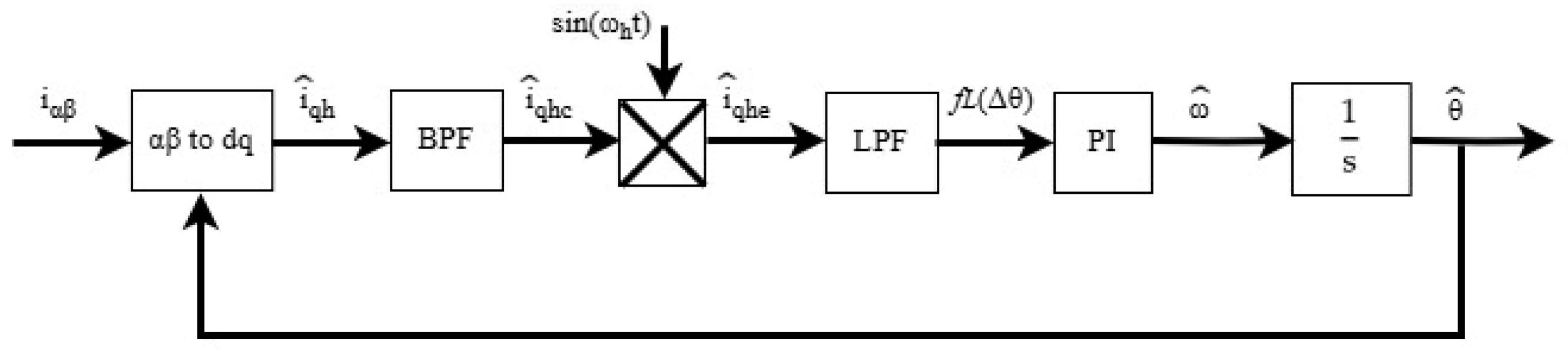
In general, the estimation process in the HF injection technique using the tracking loop control system is illustrated in
Figure 1. A BPF is used to extract the HF carrier quadrature current
, which contains rotor position information, as shown in Equation (9). This equation may face sensitivity challenges when
is small. So far, providing a clear and undistorted rotor position error signal has been useful for accurately capturing the amplitude, thereby maintaining estimation accuracy.
Then, the synchronous demodulation process is applied by multiplying sin
). After the signal modulation process, secondary harmonics, consisting of AC and DC components, appear in the resulting current. Thus, the HF quadrature current after the modulation process
can be expressed as follows:
The BPF was designed using a second-order filter, where
is the damping ratio and the natural frequency
is
and
, which can be expressed as follows:
Then, LPF is used to filter out the AC component, allowing for the signal position error information
to be extracted using the following equation:
Typically, the LPF is developed using either a first-order or second-order filter, which are expressed in Equation (14) and Equation (15), respectively.
Finally, when
is regulated to zero by the PI controller, the actual reference frame aligns with the estimated synchronous reference frame, indicating that the estimated rotor position matches the actual rotor position. This is the working principle of the HF injection technique.
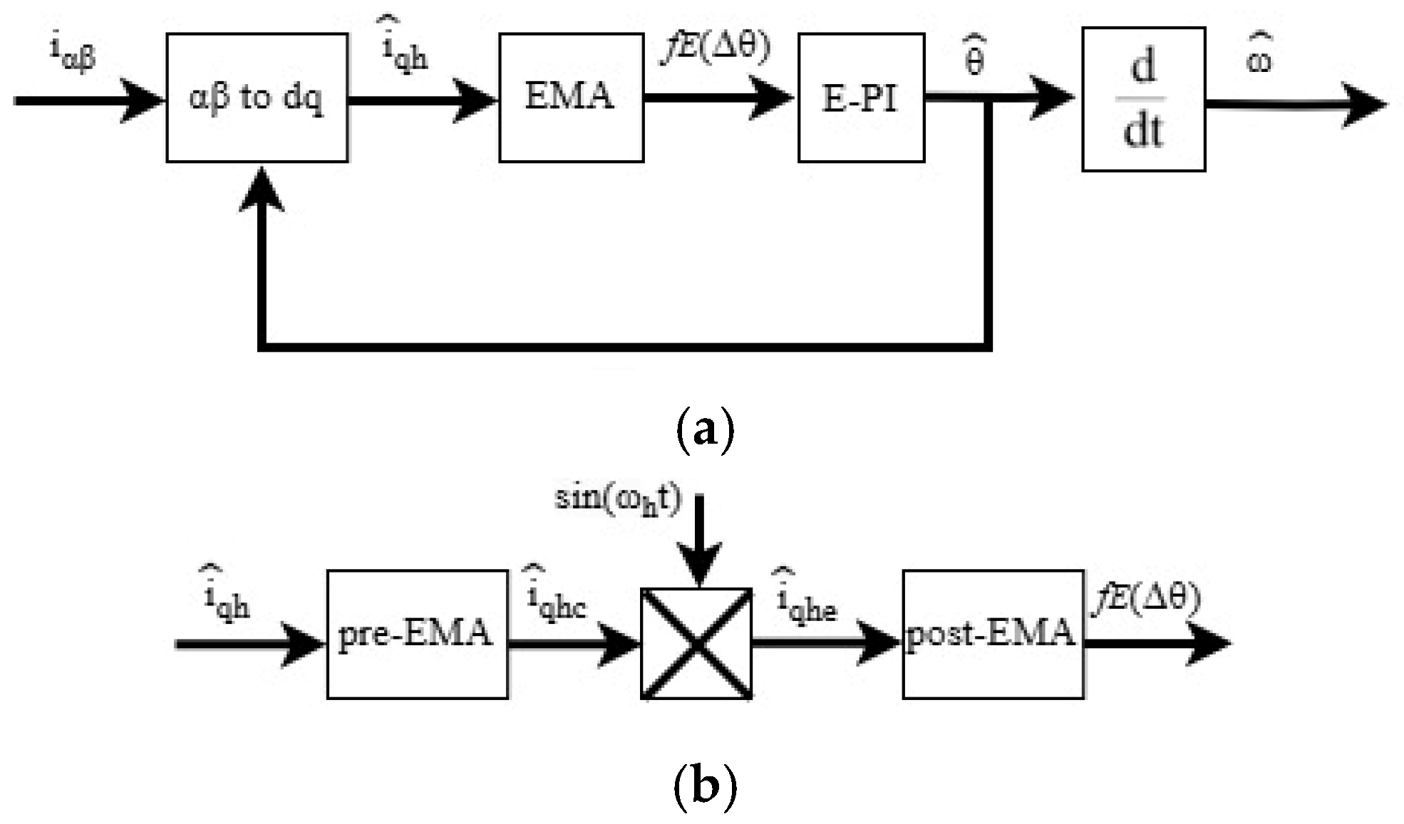
3. Proposed Implementation of Tracking Loop Control Systems for Sensorless PMSM Using the HF Injection Technique
This section presents an improvement in the extraction scheme in the tracking loop control system to estimate rotor position and motor speed. The tracking loop control system consists of two main parts: modulation signal processing, which extracts rotor position estimation error, and the PI regulator, which serves as an observer to estimate the rotor position. These components are discussed in detail throughout this section.
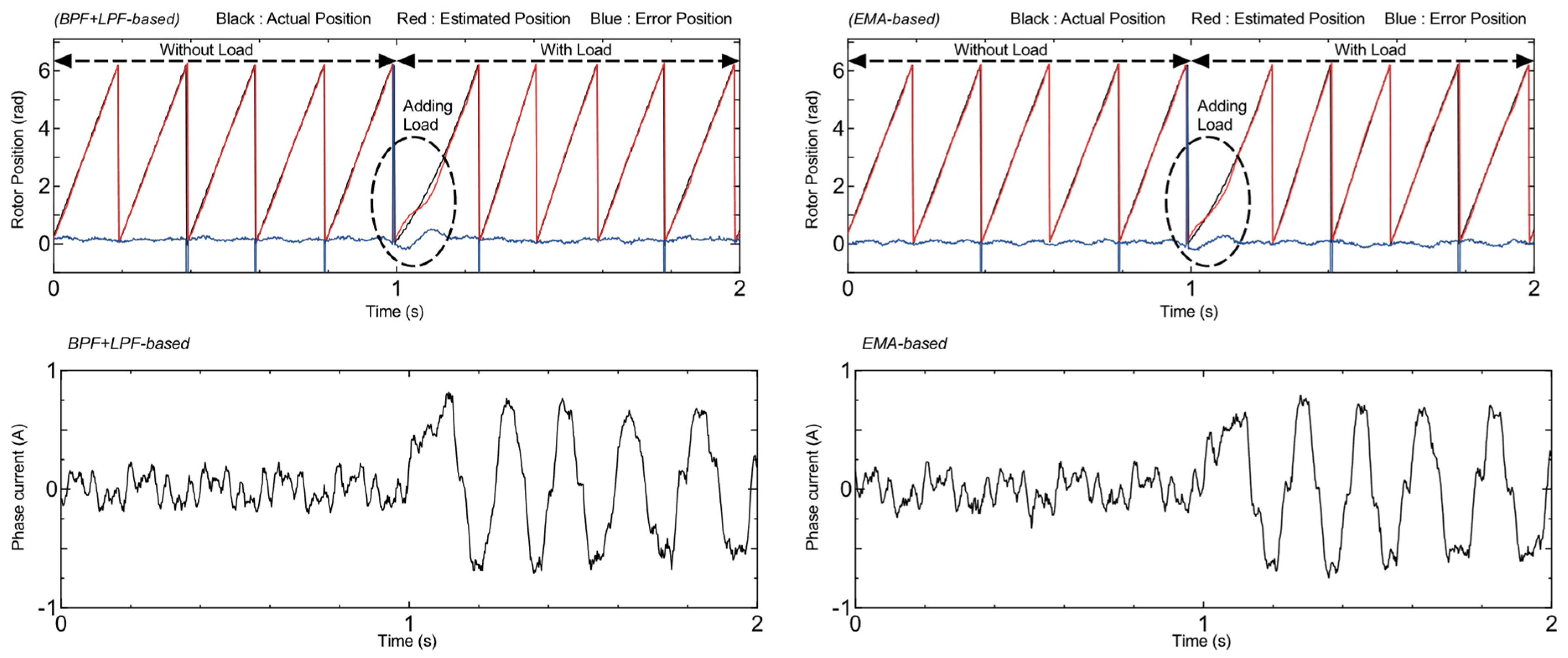
The rapid extraction of rotor position error information during dynamic changes has a positive impact on the tracking loop control system, enabling the control system to respond quickly and estimate the rotor position more accurately. In this extraction scheme, filter performance also plays a critical role in the demodulation process. Conventional signal demodulation techniques typically rely on a BPF and LPF, which may potentially narrow the bandwidth of sensorless PMSM control systems. In addition, the use of a low-order BPF can degrade the signal-to-noise ratio (SNR) of high-frequency signals, leading to unstable rotor position estimation. Conversely, a high-order BPF tends to deteriorate the dynamic response, especially during sudden changes such as speed variations, direction reversals, or abrupt load additions. Meanwhile, the design of the LPF also faces two conflicting demands. First, a wide bandwidth is required to enhance the system’s ability to respond quickly to dynamic changes. Second, the bandwidth needs to be narrowed to suppress high-frequency harmonic components. This contradiction creates a technical dilemma in the design of the demodulation system for the extraction scheme.
To address these challenges, this paper proposes an alternative demodulation technique that is more effective and can serve as a replacement for the conventional combination of BPF and LPF. The EMA is proposed due to its high responsiveness to dynamic changes and superior computational efficiency. EMA continuously updates values based on recent data by assigning greater weight to newer samples, thereby improving the system’s responsiveness to changing conditions without depending on filter level order, bandwidth, and SNR. Moreover, since EMA performs simple weighted averaging on recent data, this method significantly reduces the complexity and computational burden in digital signal processing. The transfer function of EMA in the continuous domain can be expressed as follows:
Interestingly, the EMA model resembles the LPF, as shown in Equation (14). However, the main difference between the two approaches lies in the method of determining their coefficients: the LPF operates based on a specified cut-off frequency, with coefficients chosen according to the frequency attenuation characteristics; whereas the EMA calculates a weighted average of the input signal, where the weight of the most recent data is greater, and the weight of the previous data decreases exponentially. The smoothing factor α determines the relative weighting between the most recent and previous data, which can be obtained from the number of samples in a time window based on the frequency characteristics of the signal to be passed. Therefore, in hardware implementation, the EMA offers a simpler structure, where the value of α can be directly determined using equations in the discrete-time system, as follows:
where
is the number of samples used to calculate the average with a window length determined based on the time–frequency of the data
is chosen according to the characteristic frequency of the signal to be passed so that
,
is the sampling time. Therefore, the EMA in the discrete domain can be expressed as:
In this proposed scheme, the demodulation technique for the tracking loop control system is implemented using multiple EMA stages, as illustrated in
Figure 2. The first EMA, referred to as the pre-EMA stage, is designed to set the upper and lower limit functions instead of the BPF, as expressed in Equation (19). This approach serves as a replacement for the conventional BPF, aiming to achieve improved dynamic response without depending on the filter order level or SNR.
where
and
represent the pre-EMA signals used to set the lower and upper limits of the filtered signal, respectively. Meanwhile,
denotes the high-frequency quadrature current that carries rotor position information to be modulated. The parameters
and
are the smoothing factor settings for the lower and upper limits, respectively. For instance, if the window length is set to 0.002 s, the resulting characteristic frequency of the window length is
500 Hz. According to Equation (17), the α value can then be calculated for this frequency to ensure that signals below this threshold are effectively attenuated.
In this study, the injected HF signal is set to 1 kHz. The demodulation technique is performed by modulating the HF quadrature current, which carries rotor position information due to the frequency injection. Therefore, the pre-EMA system is designed to pass signals in a frequency range around the injection frequency, with the lower limit set at 900 Hz and the upper limit set at 1.1 kHz. Since
is the EMA for the lower limit, which is obtained by subtracting between the input signal and the reduced signal, the reduced signal must be in the 100 Hz range to obtain signals around 900 Hz. Thus, when the sampling time is set to 0.0001 s, the window length for the lower limit can be set to 0.01 s, giving an
value of 0.019 to obtain the desired lower limit. Meanwhile,
is the EMA used to define the upper limit of the passed signal. Since this stage processes the output of the lower-limit EMA and passes signals below 1.1 kHz, the window length can be set to 0.0009 s. Based on this value,
can be set to 0.198, effectively passing signals in this upper frequency range. Consequently, the HF quadrature current signal passed through the pre-EMA stage can be utilized for the synchronous demodulation process. As a result, Equation (11) can be rewritten as follows:
Since the rotor position error contains both AC and DC components resulting from the synchronous demodulation process, the second-stage EMA, referred to as the post-EMA, is applied to suppress the AC component as a replacement for the conventional LPF. Accordingly, the rotor position estimation error can be expressed by rewriting Equation (13) as follows:
In this case, the AC component introduces a specific frequency into the rotor position error. To eliminate this component, the window length can be set to the lower limit at 50 Hz, which corresponds to a window length of 0.02 s, resulting in a post-EMA smoothing factor
of 0.001. Accordingly, the post-EMA is employed to extract the DC component by calculating the average values within the defined window length. Thus, rotor position information can be expressed by rewriting Equation (21) as follows:
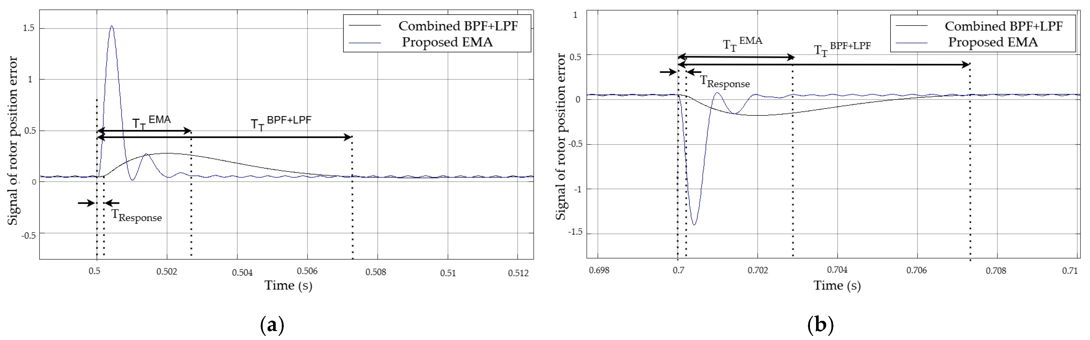
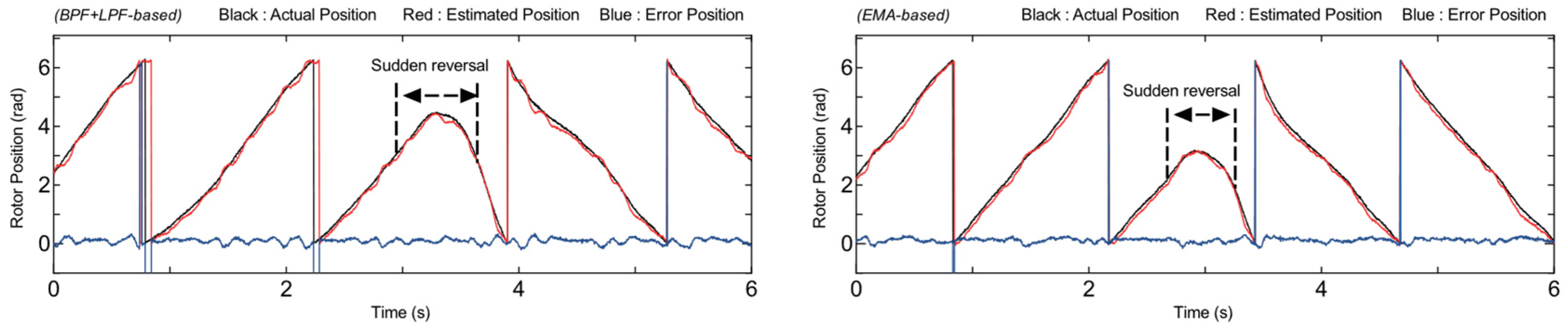
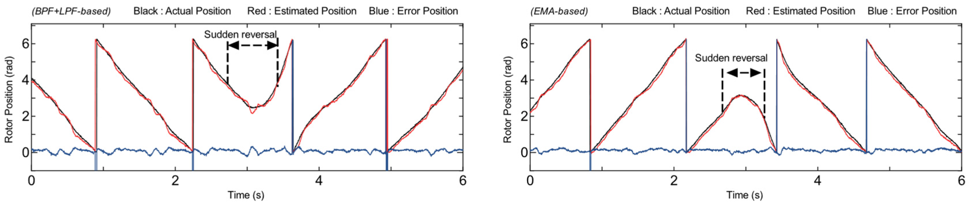
Furthermore, to observe the responsiveness of the proposed system under dynamic conditions that require quick adaptation to input signal changes, a simulation is conducted using a suddenly changed input signal to compare the performance of both extraction systems, as shown in
Figure 3.
The input signal, representing the quadrature current component in the high-frequency (HF) frame, is set to
within the time interval
. It is then changed to
during the interval
and returns to the initial signal in the interval
. Here, 1000 Hz is the injection frequency, while 20,000 Hz represents the switching frequency.
Figure 3a shows that the input signal changes at t = 0.5 s. The conventional system requires a response time (T
Response) of approximately 0.25 ms and a transient time (T
T) of about 7 ms to reach stability. This response needs to be shortened to maintain accurate rotor position estimation under dynamic conditions. In contrast, the proposed system demonstrates a faster response, with a T
Response less than 0.125 ms and a T
T of only 3 ms, indicating a significant improvement despite a slight overshoot during the transition. Subsequently, at t = 0.7 s, the system is changed while in a steady-state condition, as shown in
Figure 3b. The proposed system exhibits a faster response with T
Response and did not exceed 0.2 ms, compared to 0.35 ms in the conventional system. The transient time T
T2 also has a shorter time, at 2.8 ms compared to 7.5 ms in the conventional system. The statistical analysis shows that the standard deviation of the T
T is below 0.15 ms, confirming the consistency of the system’s faster dynamic performance. In this case, EMA is not exactly a filter that suppresses the signal, but rather a signal-smoothing technique that assigns greater weight to more recent data within a defined window length. Although the EMA output still contains slight ripples, these are eliminated in the appropriate control loop systems through parameter design that considers the cut-off frequency. Therefore, rotor position information can still be extracted quickly and accurately under dynamic conditions.
As a further process within the tracking loop control system, a PI controller with extended integration (E-PI) is adopted, where the rotor position error information is used as input to obtain the rotor position estimate
, which can be expressed by the following equation:
where
are the proportional coefficient, integral coefficient, cut-off frequency of the extraction scheme, and angular margin, respectively.
In contrast to conventional methods, the rotor position estimation in Equation (23) is performed earlier to avoid potential noise that may arise when the estimated motor speed is used as feedback in the speed control system, particularly at low speeds. In addition, to ensure that the estimated theta quickly reaches a stable condition and remains unaffected by noise in the estimated motor speed, this approach is expected to provide better performance in rotor position estimation, even under low-speed dynamic conditions. Therefore, the rotor position can be derived by a differential equation to obtain the motor speed. Then, an LPF is employed to reduce noise introduced during the differentiation process, so that the expression of the estimated motor speed, which is represented as the estimated rotor omega
, can be expressed in Equation (25). Thus, the obtained estimated rotor position and motor speed information can be used to implement real-time PMSM control without a position sensor.
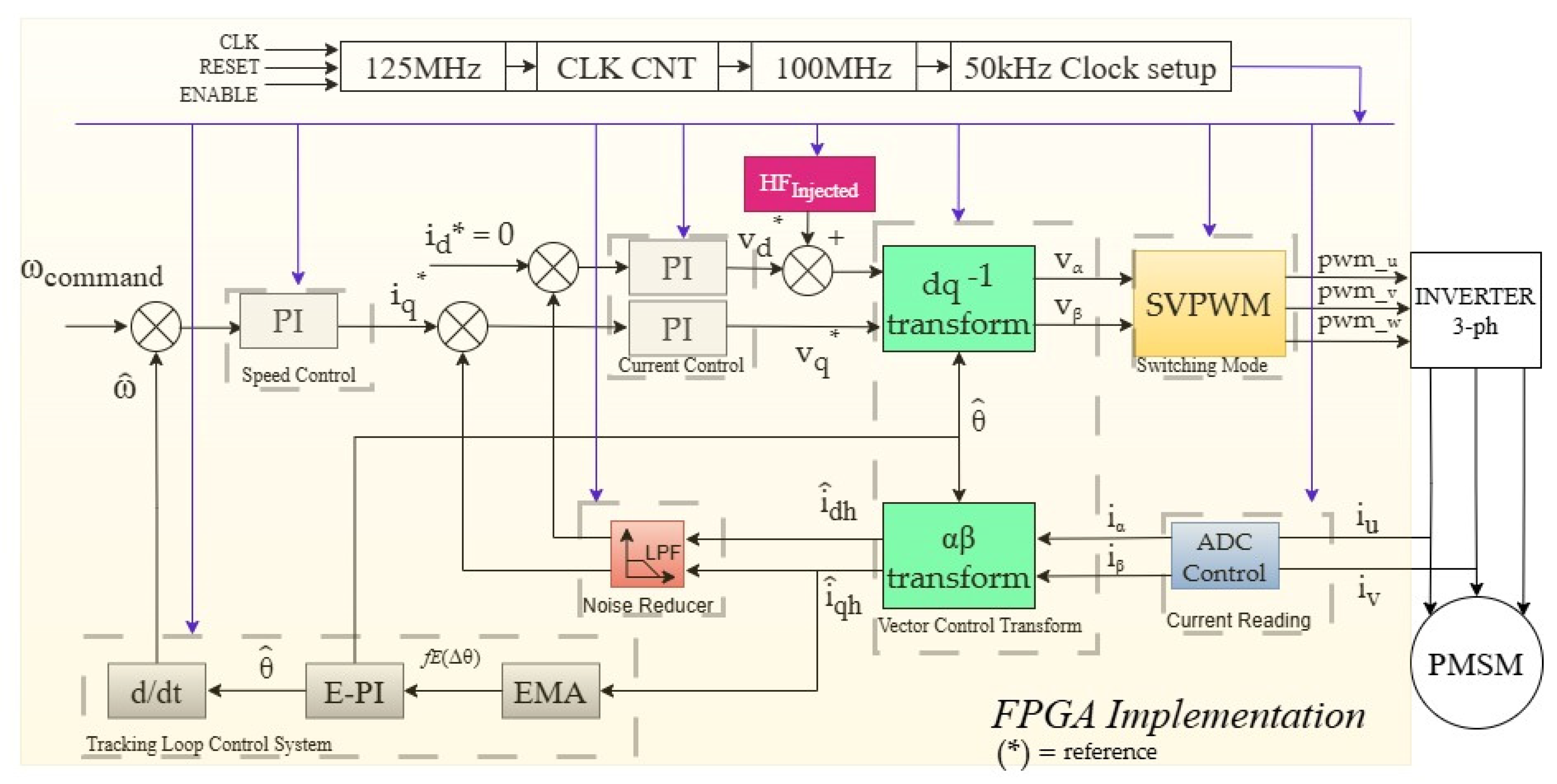
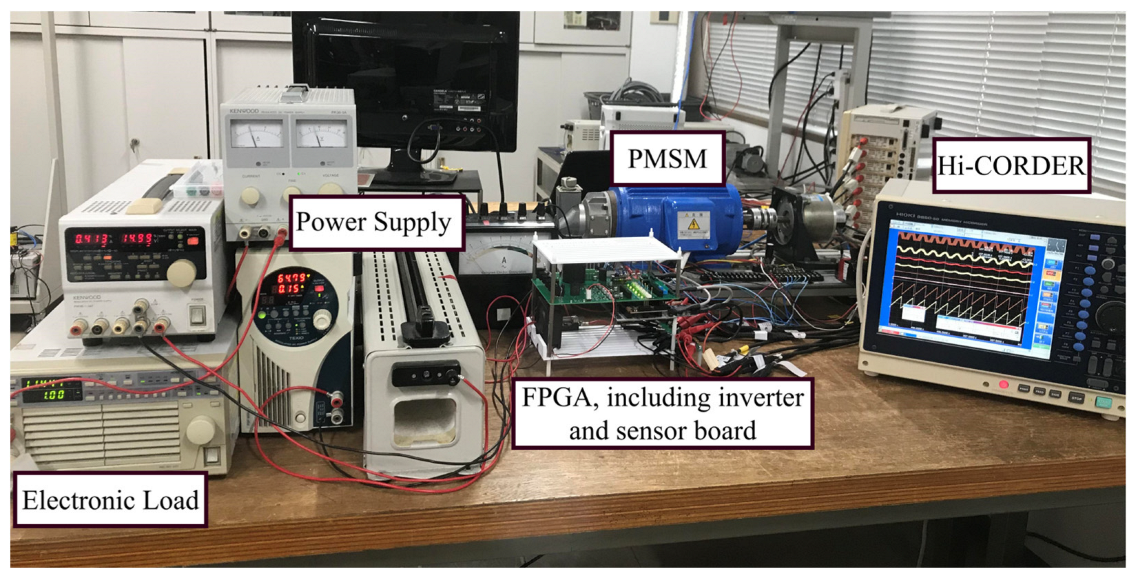
In order to realize the proposed sensorless scheme, an FPGA is selected. Due to its capability in hardware control implementation, which enables parallel processing and fast execution, a wider control-loop bandwidth can be achieved. This is beneficial for minimizing delays that may occur in the sensorless control process, such as ADC control, vector control, the estimation process, and filtering, as shown in
Figure 4.
On the other hand, to observe the efficiency of resource utilization in real-time motor control implementation using FPGA, a system-processing comparison is presented in the FPGA utilization resources between the conventional system and the proposed system, as shown in
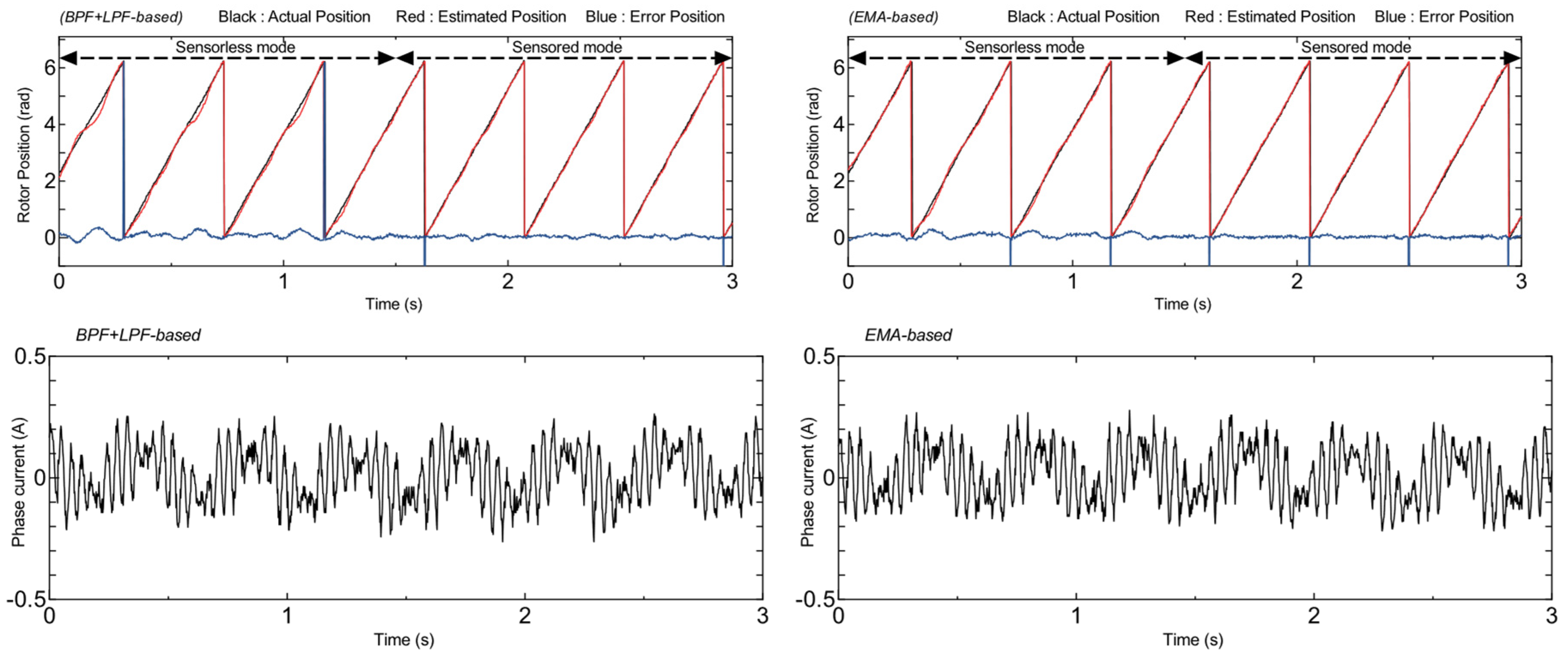
Table 1. According to this, the system using EMA shows a reduction of DSP and LUT utilization, indicating a computational system with a lighter workload. This proves that the proposed system has better efficiency in implementing real-time motor control compared to conventional systems using BPF and LPF while providing better responsiveness under dynamic conditions to improve the performance of the sensorless control technique.
Furthermore, the detailed parameters used in hardware implementation are presented in
Table 2, where the value of α is determined based on the window length. This window length can be calculated according to the frequency characteristics of the signal to be passed, as described in Equation (17). Meanwhile, the proportional and integral constants used in the E-PI controller for the tracking loop estimation process are not tuned empirically. Instead, they are analytically derived based on the cutoff frequency and the angular margin, as shown in Equation (24). These analytical formulations eliminate the need for manual parameter adjustment, thereby improving the reproducibility of the implementation in real-time sensorless control systems.


