Article

Multi-Parameter Optimization of Angle Transmission Ratio of Steer-by-Wire Vehicle

School of Automotive and Traffic Engineering, Jiangsu University, Zhenjiang 212013, China
*
Author to whom correspondence should be addressed.
World Electr. Veh. J. 2025, 16(6), 317; https://doi.org/10.3390/wevj16060317
Submission received: 24 April 2025 / Revised: 28 May 2025 / Accepted: 29 May 2025 / Published: 8 June 2025

Abstract

:
Aiming at the problem of the insufficient stability of the unified model of steering angle transmission ratio at high speeds, we introduce a novel control strategy that integrates the yaw rate gain, lateral acceleration gain, vehicle speed and steering wheel angle, achieving great improvements in a simulation. The new control strategy uses a genetic algorithm to optimize the yaw rate and lateral acceleration gain values at different speeds, and the two are weighted. The ideal variable-angle transmission ratio control strategy is designed by using the unified model of steering angle transmission ratio at different speed intervals. The simulation results show that the strategy reduces the steering wheel angle peak by 67.12% compared with the fixed-angle transmission at low speeds. Compared with the unified model of steering angle transmission ratio at high speeds, the peak values of the yaw rate, the lateral acceleration and sideslip angle of the vehicle are reduced by 7%, 5.67% and 11.67%, respectively, which effectively improves the steering stability of the vehicle.

1. Introduction

The traditional vehicle steering angle transmission ratio has a limited range of variation during the steering process, and even remains constant [1], which makes it difficult for the vehicle to take into account the steering portability under low-speed conditions and the steering stability under high-speed conditions; it cannot achieve an ideal handling performance [2]. In contrast, steer-by-wire vehicles eliminate mechanically connected components, thereby greatly increasing the design flexibility of the steering angle transmission ratio [3].
In recent years, many achievements have been made in the research of variable-angle transmission ratio design. Kou [4] considered the yaw rate gain, lateral acceleration gain and vehicle speed to design the variable-angle transmission ratio. A neural network was used to select the gain value, and a fixed weight was used to design the yaw rate gain and lateral acceleration gain. The results show that the vehicle handling stability can be improved. Lin et al. [5] used fuzzy neural network technology to design the variable-angle transmission ratio considering vehicle speed, steering wheel angle and yaw rate gain, which significantly reduced the driver’s operating burden and improved the vehicle’s handling stability. Liu et al. [6] used particle swarm optimization to optimize the yaw rate gain value and considered the steering wheel angle and yaw rate gain to design the variable-angle transmission ratio. The simulation proved that the vehicle’s path-following ability and stability were improved. Xu [7] designed a variable-angle transmission ratio considering yaw rate gain, vehicle speed and steering wheel angle and dynamically selected it by a fuzzy algorithm to make the steering more flexible. Feng [8] considered the yaw rate gain, lateral acceleration gain and vehicle speed to design the variable-angle transmission ratio, so as to realize the accurate control of the angle transmission ratio when a vehicle is running. Zhang [9] proposed a unified model of the steering angle transmission ratio, which considers yaw rate gain, vehicle speed and steering wheel angle to design a variable-angle transmission ratio. Based on the yaw rate gain, a steering variable-angle transmission ratio suitable for different speed regions was designed. The simulation results showed that the strategy can achieve more accurate variable-angle transmission ratio control.
It can be seen that the yaw rate gain, lateral acceleration gain, vehicle speed and steering wheel angle all have an impact on the design of the variable-angle transmission ratio. Aiming at the problem of the insufficient stability of the unified model of steering angle transmission ratio at high speeds in reference [9], we introduce a new variable-angle transmission ratio control strategy, which integrates yaw rate gain, lateral acceleration gain, vehicle speed and steering wheel angle. The new control strategy uses a genetic algorithm to optimize the yaw rate and lateral acceleration gain values at different speeds, and the two are weighted. The ideal variable-angle transmission ratio control strategy is designed by using the unified model of steering angle transmission ratio at different speed intervals.

2. Steer-by-Wire Vehicle Model

The construction of the model is the basis for the design of the variable-angle transmission ratio control strategy, which provides a theoretical basis and simulation platform for the subsequent parameter optimization and variable-angle transmission ratio design.

2.1. Differential Formula of Steer-by-Wire System

Before building the steer-by-wire system model, it is necessary to build a physical model [10]. The steer-by-wire system model is mainly composed of a steering execution motor model and rack and pinion model [11]. Reduced-order modeling technology [12] is used to model the steer-by-wire system.
(1) The dynamic formula of the steering execution motor is as follows [8]:
T f m = J f m θ f m ¨ + B f m θ f m . + K f c ( θ f m / g f m x r / r p ) g f m .
where T f m is the electromagnetic torque of the motor in the steering system; J f m is the motor moment of inertia; θ f m is the motor rotation angle; B f m is the damping of the motor; K f c is the torsional stiffness of the motor; g f m is the motor reduction ratio; x r is the gear movement stroke; and r p is the radius of the pinion.
The electric potential balance formula of the steering execution motor is as follows [8]:
U f a = R f a I f a + L f a I f a . + K f e θ f m ; . T f m = K f t I f a .
where U f a is the motor voltage; R f a is the motor resistance; I f a is the motor current; L f a is the motor inductance; K f e is the back electromotive force of the motor; and K f t is the motor electromagnetic torque coefficient.
(2) The dynamic formula of the rack and pinion is as follows [8]:
M r x r ¨ + B r x r . + T f l l f l + T f r l f r = K f c ( θ f m / g f m x r / r p ) r p .
where M r is the weight of the gear rack of the steering gear; B r is the gear rack damping of the steering gear; T f l , T f r represent the rotational torque of the main pin of the front wheel of the steering gear; and l f l , l f r represent the length of the steering rocker arm of the front wheel of the steering gear.

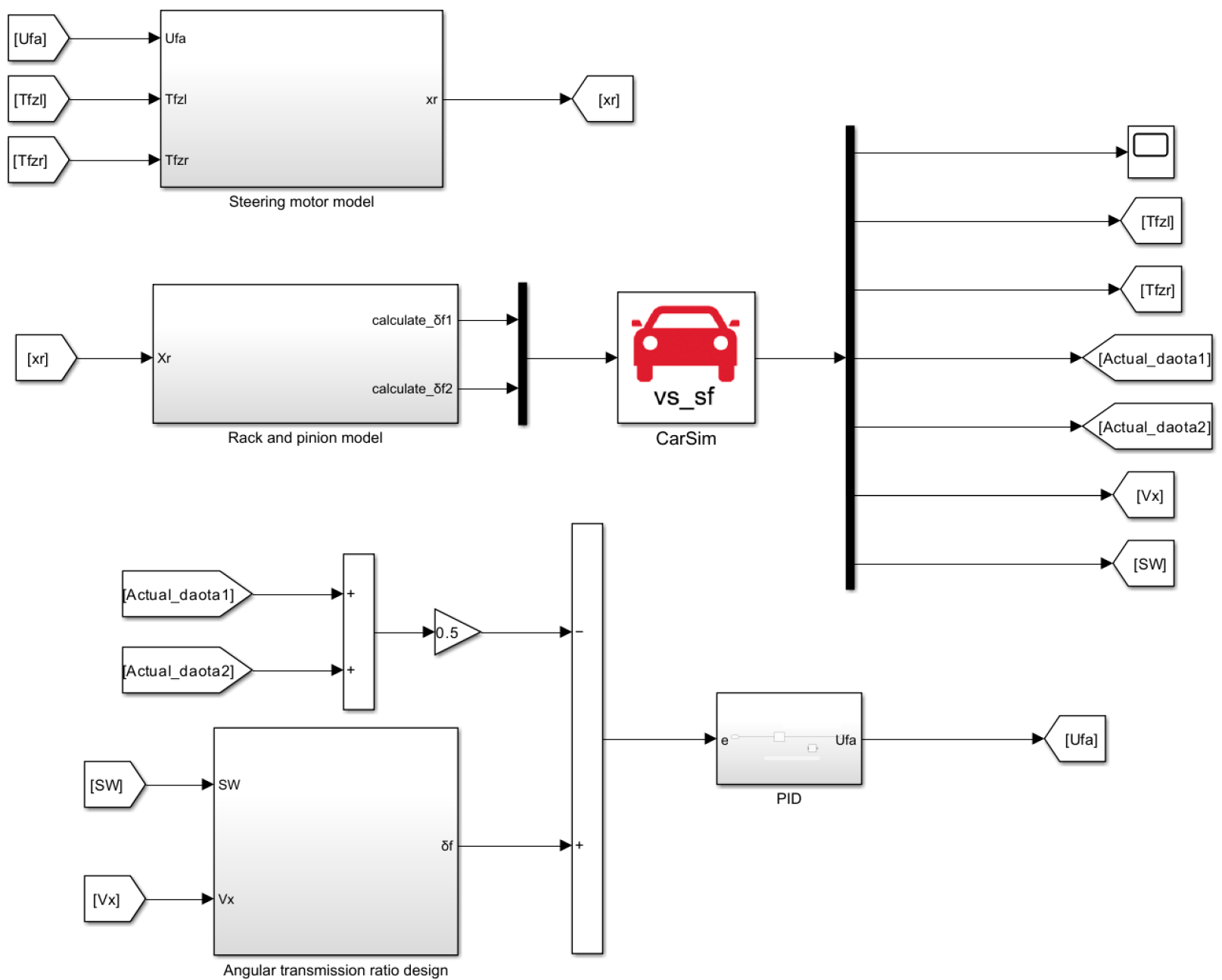
2.2. Establishment of the Steer-by-Wire Vehicle Model

According to the differential formula established in Section 2.1, a steer-by-wire vehicle model is built in conjunction with Carsim (Carsim2020, Mechanical Simulation Corporation, Ann Arbor, MI, USA). The main parameters of the vehicle are shown in Table 1, and the steer-by-wire vehicle model is shown in Figure 1.
With the input of the vehicle speed and steering wheel angle, the expected front wheel angle is obtained. The steering execution motor adopts PID control. The error obtained by subtracting the expected front wheel angle from the actual front wheel angle is taken as the input, and the voltage signal of the steering execution motor is taken as the output. Then the steering wheel angle is calculated by the steering actuator and input into the CarSim vehicle model.

3. Optimization of Unified Model of Steering Angle Transmission Ratio

3.1. Unified Model of Steering Angle Transmission Ratio

According to research in the relevant literature [13], the steering variable-angle transmission ratio design has a high ‘center ratio’ and is affected by the steering wheel angle, which can improve the vehicle’s rapid response ability. In reference [9], a unified model of the steering variable-angle transmission ratio is proposed, and the formula of the angle transmission ratio is designed according to the vehicle speed, yaw rate gain and steering wheel angle, as shown in Formula (4).
H = i max ; B = i min ; A = H B n o r m p d f ( 0 , 0 , σ ) ; i t y = A 2 π σ exp ( δ s w 2 2 σ 2 ) + B ;         = A n o r m p d f ( δ s w , u , σ ) + B .
where i max , i min represent the angle transmission ratio maximum and minimum value; H, B represent the amplitude coefficient of the angle transmission ratio; A is the variation range of the angle transmission ratio value; σ is the coefficient of change in the central ratio; δ s w is the steering wheel angle; n o r m p d f is the normal function; and u is the mean value of the normal function, its value is taken as 0.
The design parameters of the variable-angle transmission ratio do not include the lateral acceleration gain, which will result in insufficient high-speed steering stability [9]. The two design methods of constant yaw rate gain and constant lateral acceleration gain were compared, and the deficiency of considering only one factor in the design was concluded.

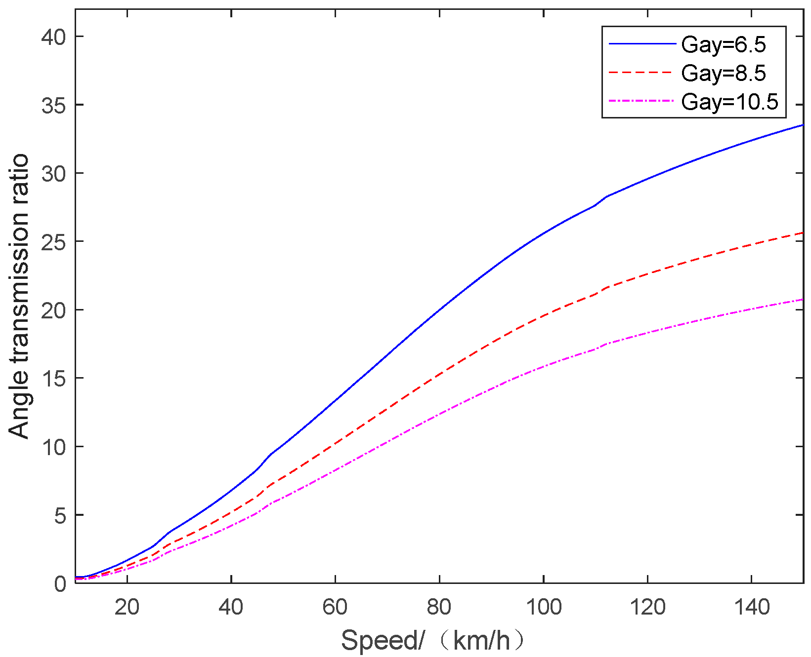
3.2. Different Variable-Angle Transmission Ratio Design of SBW Vehicle

The formula [14] for the design of the angle transmission ratio based on the constant gain of the yaw rate is shown in Formula (5):
i s w = v x / L [ 1 + K v x 2 ] G s w .
where v x is the vehicle’s traveling speed; L is the distance from the front axle to the rear axle; K is the vehicle’s stability factor; and G s w is the gain value of the vehicle’s yaw rate.
The formula [14] for the design of the angle transmission ratio based on a constant lateral acceleration gain is as follows (6):
i a y = v x v x / L [ 1 + K v x 2 ] G a y .
where G a y is the lateral acceleration gain.
According to Formulas (5) and (6), the relationship curves of different yaw rate gains and lateral acceleration gains with the angle transmission ratio are established, and the curves are shown in Figure 2 and Figure 3.
As shown in Figure 2, the angle transmission ratio increases with the increase in vehicle speed at medium and low speeds, but decreases at high speeds. The steering response performance of the vehicle is accelerated, and the steering stability is deteriorated. In Figure 3, the angle transmission ratio increases with the increase in vehicle speed, which satisfies the criteria for high-speed steering stability. However, compared with the yaw rate gain, the lateral acceleration gain is more affected by the vehicle speed. Therefore, it is necessary to calculate the two weights to meet the ideal steering demand.

3.3. Variable-Angle Transmission Ratio Design Strategy

According to the unified model of steering angle transmission ratio and the comparative analysis of the design using a constant yaw rate gain and a constant lateral acceleration gain, a variable-angle transmission ratio speed interval control strategy is designed. The control strategy is as follows:
Low-speed section: The aim is to achieve ‘low-speed steering portability’ while avoiding the excessive sensitivity of the vehicle [15]. Therefore, it is only necessary to make adjustments according to the steering wheel angle, without taking into account the change in vehicle speed.
Medium-speed section: Multiple parameters such as the yaw rate gain, vehicle speed and steering wheel angle should be considered at the same time.
High-speed section: It is necessary to comprehensively consider the vehicle speed, yaw rate gain, steering wheel angle and lateral acceleration gain to achieve high-speed steering stability.
When designing the variable-angle transmission ratio with the unified model of steering angle transmission ratio, the design parameters include the yaw rate gain, vehicle speed and steering wheel angle. The amplitude coefficients H and B at medium and low speeds can be directly designed. However, at high speeds, the amplitude coefficients H and B need to be calculated using the weighting formula, which is shown in Formula (7) [8].
i j q = M v x / L [ 1 + K v x 2 ] G s w + N v x v x / L [ 1 + K v x 2 ] G a y .
where i j q is the angle transmission ratio obtained by weighting; and M and N represent the proportions of the angle drive ratios of the two gain designs.
Among them, the values of M and N need to satisfy the following points [8]:
(1) When vx = 80 km/h, M = 1 and N = 0;
(2) When vx = 120 km/h, the transmission ratio in Formula (7) is approximately 23;
(3) M + N = 1;
(4) M is a linear decreasing function and N is a linear increasing function.
Under the above four conditions, the coefficients M and N of the weight function varying with the vehicle speed are obtained, as shown in Formula (8):
M = 0.01396 v x + 2.1168 ; N = 0.01396 v x 1.1168 .

4. Optimization of Yaw Rate and Lateral Acceleration Gain Value

The selection of the yaw rate and lateral acceleration gain value is closely related to the control effect [16]. Using a genetic algorithm, the evaluation index of the handling stability is set as the objective function, and the yaw rate and lateral acceleration gain value required for variable-angle transmission ratio design are optimized at different speeds.

4.1. Genetic Algorithm

A genetic algorithm is selected to optimize the gain value because of its global search ability, fast optimization and strong robustness. Many kinds of genetic algorithms have been developed so far. This research focuses on the design of an ideal variable-angle transmission ratio. Therefore, the genetic algorithm is optimized by using the genetic algorithm toolbox of Matlab R2018a. The comprehensive evaluation index of the vehicle handling stability is taken as the fitness function, which is written in the script file of Matlab R2018a. At the same time, the population is selected, crossed and mutated. The population size and iteration algebra are selected to be 200, and the crossover probability and mutation probability are selected to be 0.6 and 0.01, respectively. The genetic algorithm library function of Matlab is used to call the joint simulation model of Simulink (Simulink in MATLAB R2022b, Natick, MA, USA) at the same time. The global optimal fitness value is obtained by an iterative method. The flow chart of the genetic algorithm to optimize the gain value is shown in Figure 4.

4.2. Handling Stability Evaluation Index

The handling stability of the vehicle is objectively evaluated from the following multiple aspects, and the evaluation indicators are as follows [17,18]:
① During the operation of a vehicle, it is essential to ensure that one can control the vehicle as one sees fit. This is the foundation for ensuring that the vehicle is actively safe. The quality of track tracking performance is a key indicator to measure whether a car can accurately respond to the driver’s wishes. The calculation formula for the trajectory tracking error is as follows:
J e 1 = 0 t n f t y t E 2 d t ; J e 2 = 0 t n v x β β 2 d t ; J E = W e 1 J e 1 2 + W e 2 J e 2 2 W e 1 + W e 2 .
where f t is the expected route of driving; y t is the actual route of driving; E is the threshold of the trajectory deviation, which is 0.4 m; β is the threshold of the lateral deflection angle velocity, which is 0.8 rad/s; W e 1 , W e 2 represent weighted coefficients; and t n is the test time.
② The driver’s control burden is a key indicator for evaluating the vehicle’s handling performance and the active safety of the human–vehicle closed-loop system. The variance calculation formula of the control burden is as follows:
J b 1 = 0 t n δ s w δ s w 2 d t ;   J b 2 = 0 t n T s w T s w 2 d t ;   J B = W b 1 J b 1 2 + W b 2 J b 2 2 W b 1 + W b 2 .
where δ s w is the angle velocity when turning the steering wheel; δ s w is 1 rad/s; T s w is the steering wheel control torque; T s w is 8 N∙m; and W b 1 , W b 2 represent weighted coefficients.
③ When a vehicle turns, if the lateral acceleration or the body’s roll angle is too large, it will increase the driver’s mental burden and further affect the safety of the vehicle. The variance of rollover risk is calculated as follows:
J r 1 = 0 t n a y a y 2 d t ;   J r 2 = 0 t n ϕ ϕ 2 d t ;   J R = W r 1 J r 1 2 + W r 2 J r 2 2 W r 1 + W r 2 .
where a y is the lateral acceleration of the vehicle; a y is 3 m/s2; ϕ is the roll angle of the vehicle; ϕ is 3°; and W r 1 , W r 2 represent weighted coefficients.
④ The sideslip phenomenon of the front and rear wheels of a vehicle is directly related to the level of safety when driving. When the lateral forces on the front and rear wheels of a vehicle exceed the adhesion force of the ground, it will cause the vehicle to skid sideways. The calculation formula for the standard total variance is as follows:
J s i = 0 t n F y i t / F z i t μ 2 d t , J S = max J s 1 , J s 2 .
where F y 1 , F y 2 represent the lateral force of the front and rear wheels of the vehicle; F z 1 , F z 2 represent the vertical loads on the front and rear wheels of the vehicle; and μ is the threshold of the adhesion coefficient, which is 0.3.
⑤ The above-mentioned evaluation indicators are weighted and combined, and their weighted average values are calculated to construct an objective evaluation index system that comprehensively reflects the active safety of automobiles. The calculation formula of the overall evaluation index is as follows:
J T E = W E J E 2 + W B J B 2 + W R J R 2 + W S J S 2 W E + W B + W R + W S .
where W E , W B , W R , W S represent the weights assigned by the above-mentioned indicators, which are 0.25.

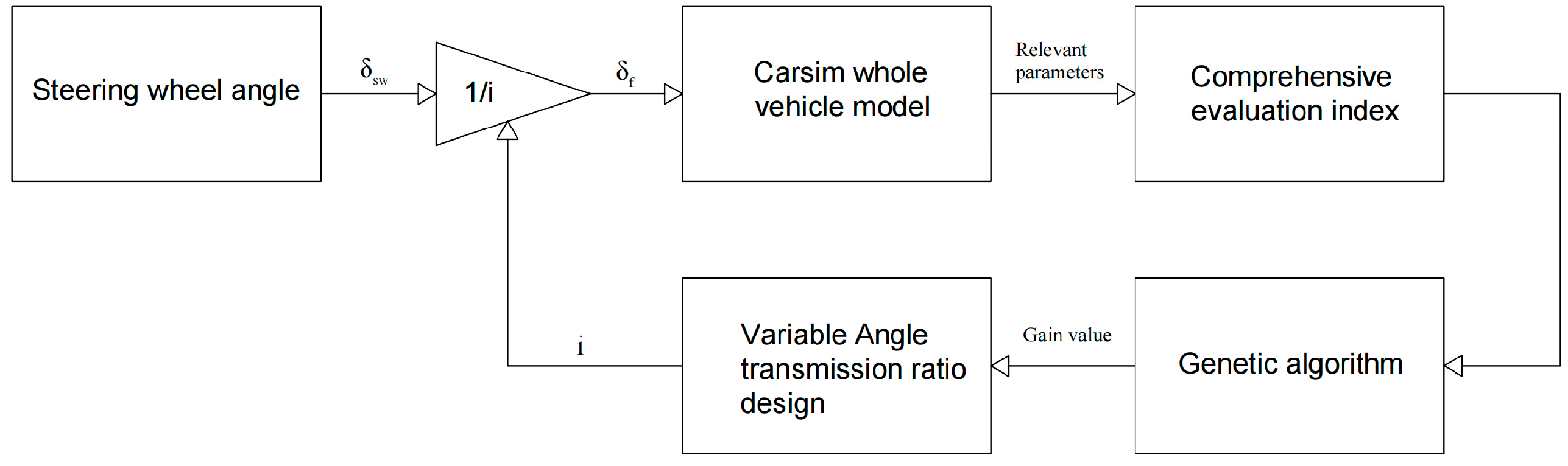
4.3. Gain Value Optimization

Taking the double-lane-change condition as an example, the road adhesion coefficient is set to 0.85, and then the optimal value of the variable-angle transmission ratio under different vehicle speeds is determined. The optimization objective is to minimize the function value to determine the gain values of the yaw rate and lateral acceleration at different speeds.
When optimizing the yaw rate gain value at full speed, the vehicle speed is set to 30, 50, 70, 90 and 110 km/h to determine the optimal yaw rate gain value. The optimization results corresponding to different vehicle speeds are shown in Table 2.
When optimizing the lateral acceleration gain value in the high-speed section, the vehicle speed is set to 70, 90 and 110 km/h to determine the optimal lateral acceleration gain value. The optimization results corresponding to different vehicle speeds are shown in Table 3.

5. Variable-Angle Transmission Ratio Design Method

Based on the design method and gain value optimization results obtained from the above analysis, the variable-angle transmission ratio control strategy of this paper is established. Firstly, the speed range is divided, and the variable-angle transmission ratio control strategy is formulated for different speed ranges. The velocity range is divided into the following categories: low speed (0–25 km/h), low speed to medium speed (25–35 km/h), medium speed (35–75 km/h), medium speed to high speed (75–85 km/h) and high speed (85–150 km/h) [18]. Finally, the variable-angle transmission ratio control strategy of each speed range is integrated to form a comprehensive strategy suitable for the full speed range.

5.1. Variable Angle Transmission Ratio Control Within Different Speed Ranges

5.1.1. Low-Speed Section

The design formula of the low-speed angle transmission ratio is shown in Formula (14), and the value of Hlow is set to vx = 25 km/h and Gsw = 0.51. According to reference [19], the maximum travel of the SBW steering wheel angle is set to ±150°, the maximum travel of the front wheel angle is set to 40° and Blow is the ratio of the maximum travel of the steering wheel angle to that of the front wheel angle. σ is 40 [9].
H l o w = 25 / 3.6 / L 0.51 ( 1 + K 25 2 / 3.6 2 ) ; B l o w = 150 / 40 = 3.75 ; A l o w = H l o w B l o w n o r m p d f ( 0 , 0 , 40 ) ; i l o w = B l o w + A l o w n o r m p d f ( δ s w , 0 , 40 ) .
where Hlow, Blow represent the amplitude coefficient of the angle transmission ratio in the low-speed section; L is the distance from the front axle to rear axle; K is the vehicle stability factor; Alow is the variation range of the angle transmission ratio in the low-speed section; δ s w is the steering wheel angle; n o r m p d f is the normal function; and ilow is the variable-angle transmission ratio designed for the low-speed section.

5.1.2. Medium-Speed Section

Formula (15) is the design formula for the angle transmission ratio in the medium-speed section, and Hmid is set as the value when Gsw = 0.32. Blow is the value when Gsw = 0.51; σ is 20 [9].
H m i d = v x / 3.6 / L 0.32 ( 1 + K v x 2 / 3.6 2 ) ; B m i d = v x / 3.6 / L 0.51 ( 1 + K v x 2 / 3.6 2 ) ; A m i d = H m i d B m i d n o r m p d f ( 0 , 0 , 20 ) ; i m i d = B m i d + A m i d n o r m p d f ( δ s w , 0 , 20 ) .
where Hmid, Bmid represent the amplitude coefficient of the angle transmission ratio in the medium-speed section; Amid is the variation range of the angle transmission ratio in the medium-speed section; vx is the vehicle speed; and imid is the variable-angle transmission ratio designed for the medium-speed section.

5.1.3. High-Speed Section

Formula (16) is the formula for the high-speed angle transmission ratio, and Hhigh is set as the value when Gsw = 0.26 and Gay = 7. Bhigh is the value when Gsw = 0.28 and Gay = 7.95; σ is 20 [9].
H h i g h = M v x / 3.6 / L 0.26 ( 1 + K v x 2 / 3.6 2 ) + N v x 2 / 3.6 2 / L 7 ( 1 + K v x 2 / 3.6 2 ) ; B h i g h = M v x / 3.6 / L 0.28 ( 1 + K v x 2 / 3.6 2 ) + N v x 2 / 3.6 2 / L 7.95 ( 1 + K v x 2 / 3.6 2 ) ; A h i g h = H h i g h B h i g h n o r m p d f ( 0 , 0 , 20 ) ; i h i g h = B h i g h + A h i g h n o r m p d f ( δ s w , 0 , 20 ) .
where Hhigh, Bhigh represent the amplitude coefficient of the angle transmission ratio in the high-speed section; Amid is the variation range of the angle transmission ratio in the high-speed section; M, N represent the coefficients of the weight function that vary with the vehicle speed; and ihigh is the variable-angle transmission ratio designed for the high-speed section.

5.2. Variable Angle Transmission Ratio in the Speed Transition Interval

In order to ensure the smooth transition of the steering angle transmission ratio during the transition from low speeds to medium speeds and from medium speeds to high speeds, the amplitude coefficients H and B of the steering variable-angle transmission ratio will increase with the increase in the vehicle speed, while the center ratio gradient coefficient will gradually decrease with the increase in the vehicle speed [9]. H25, B25, H35 and B35 are calculated based on the control strategy of the low-speed and medium-speed angle transmission ratio. H75, B75, H85 and B85 are obtained based on the angle transmission ratio control strategy of the medium-speed section and high-speed section. Formula (17) is the design formula for the angle transmission ratio from low speeds to medium speeds. Formula (18) is the design formula of the angle transmission ratio from medium speeds to high speeds. σ 25 takes a value of 40, σ 35 takes a value of 20, σ 75 takes a value of 20 and σ 85 takes a value of 20 [9].
H l o w m i d = H 25 + ( H 35 H 25 ) ( v x 25 ) / 10 ; B l o w m i d = B 25 + ( B 35 B 25 ) ( v x 25 ) / 10 ; σ l o w m i d = σ 25 + ( σ 35 σ 25 ) ( v x 25 ) / 10 ; A l o w m i d = H l o w m i d B l o w m i d n o r m p d f ( 0 , 0 , σ l o w m i d ) ; i l o w m i d = B l o w m i d + A l o w m i d n o r m p d f ( δ s w , 0 , σ l o w m i d ) .
where Hlowmid, Blowmid represent the amplitude coefficient of the angle transmission ratio in the low-speed to medium-speed section; Alowmid is the variation range of the angle transmission ratio in the low-speed to medium-speed section; ilowmid is the variable-angle transmission ratio designed for the low-speed to medium-speed section; and σ l o w m i d is the coefficient of the change in the central ratio in the low-speed to medium-speed section.
H m i d h i g h = H 75 + ( H 85 H 75 ) ( v x 75 ) / 10 ; B m i d h i g h = B 75 + ( B 85 B 75 ) ( v x 75 ) / 10 ; σ m i d h i g h = σ 75 + ( σ 85 σ 75 ) ( v x 75 ) / 10 ; A m i d h i g h = H m i d h i g h B m i d h i g h n o r m p d f ( 0 , 0 , σ m i d h i g h ) ; i m i d h i g h = B m i d h i g h + A m i d h i g h n o r m p d f ( δ s w , 0 , σ m i d h i g h ) .
where Hmidhigh, Bmidhigh represent the amplitude coefficient of the angle transmission ratio in the medium-speed to high-speed section; Amidhigh is the variation range of the angle transmission ratio in the medium-speed to high-speed section; imidhigh is the variable-angle transmission ratio designed for the medium-speed to high-speed section; and σ m i d h i g h is the coefficient of the change in central ratio in the medium-speed to high-speed section.

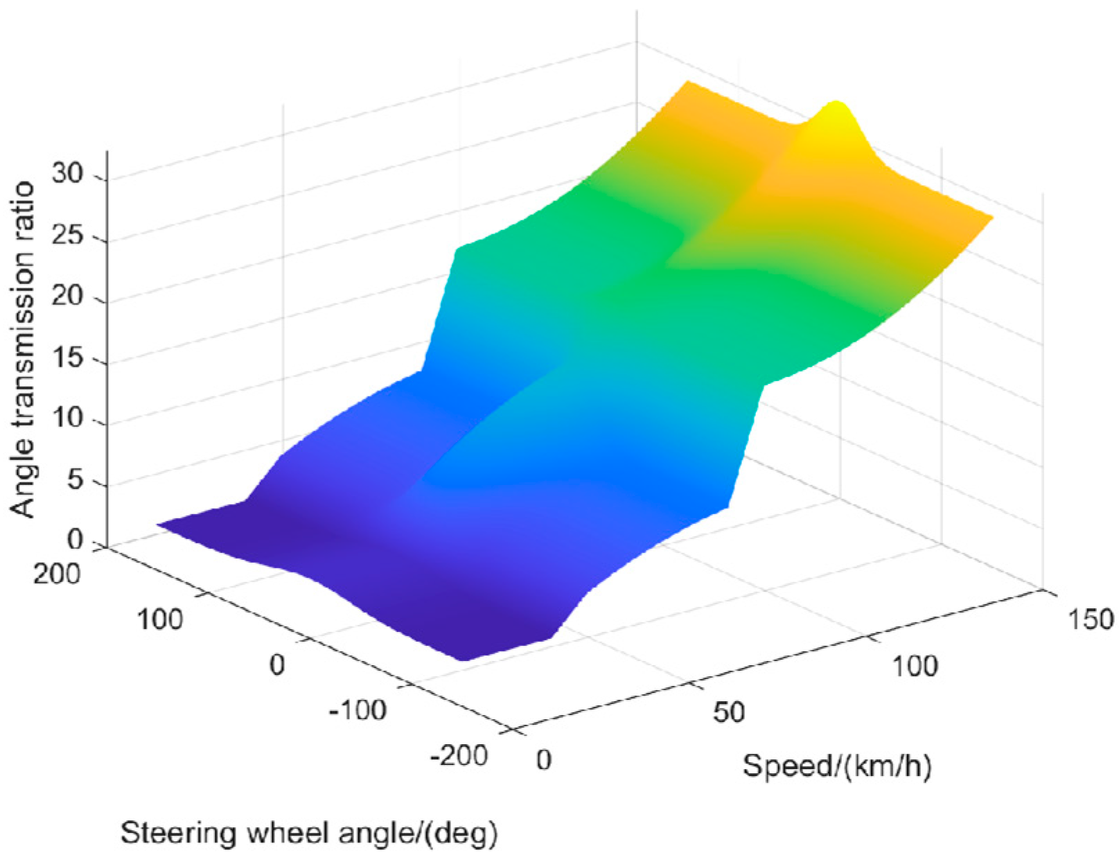
5.3. Full-Speed Variable-Angle Transmission Ratio Control

The variable-angle transmission ratio designed in five speed ranges is summarized, and a three-dimensional surface diagram of vehicle speed, steering wheel angle and angle transmission ratio is established, as shown in Figure 5. When the vehicle is driven, according to the speed and the steering wheel angle, the optimal steering angle transmission ratio under the current vehicle condition can be obtained by looking at the table [20].

6. Test Verification

In order to verify the effectiveness of the ideal variable-angle transmission ratio design, based on the steer-by-wire vehicle model established in Section 2, verification is carried out a joint simulation using Carsim and Simulink in the low-speed and high-speed sections.

6.1. Low-Speed Section Test Verification

The low-speed section test verification uses a double-shift line, and the working conditions are set as follows: the road adhesion coefficient is 0.85, and the speed is 30 km/h. The simulation results of the fixed-angle transmission ratio, constant yaw rate gain and the control strategy of this article are compared. The simulation results are shown in Figure 6.
As shown in Figure 6c and Table 4, compared with the fixed-angle transmission ratio, the peak value of the steering wheel angle is reduced by 67.12%, which reduces the operating burden during steering. As shown in Figure 6a,b, compared with fixed-angle transmission ratio and constant yaw rate gain, the control strategy of this article is also optimized in terms of the yaw rate and lateral acceleration, which improves the handling stability of the vehicle.

6.2. High-Speed Section Test Verification

The high-speed section test verification adopts the steering wheel angle step. The working conditions are set as follows: the road adhesion coefficient is 0.85, the speed is 120 km/h, the steering wheel angle is 40° and the step time is 0.5 s. The simulation results of the fixed-angle transmission ratio, the constant yaw rate gain, the unified model of steering angle transmission ratio and the control strategy of this article are compared. The simulation results are shown in Figure 7.
According to Figure 7, compared with the fixed-angle transmission ratio and constant yaw rate gain, the control strategy of this article reduces the lateral acceleration, yaw rate and sideslip angle of the vehicle. According to the high-speed control data in Table 5, compared with the unified model of steering angle transmission ratio, the control strategy of this article reduces the peak values of the yaw rate, lateral acceleration and sideslip angle at high speeds by 7%, 5.6% and 11.6%, respectively, which makes the steering more stable at high speeds.

7. Conclusions

The design parameters of the variable angle transmission ratio include the yaw rate gain, lateral acceleration gain, vehicle speed and steering wheel angle. Ignoring any parameter during the design process will result in the inability to obtain the ideal variable angle transmission ratio. Therefore, this paper proposes to comprehensively consider four parameters and design a new variable angle transmission ratio control strategy.
Firstly, a model of a steer-by-wire vehicle is built. Based on the unified model of steering angle transmission ratio, its shortcomings are analyzed by a simulation, and the comprehensive control strategy of variable-angle transmission ratio is proposed. According to the speed division interval, the genetic algorithm is used to optimize the gain value at different speeds. Based on the unified model of steering angle transmission ratio, a three-dimensional surface diagram of vehicle speed, steering wheel angle and angle transmission ratio at full speed is drawn using an interval design. The low-speed and high-speed simulation data show that compared with the constant-angle transmission ratio and the constant-yaw-rate-gain design, the variable-angle transmission ratio designed in this paper can optimize the vehicle handling stability at low speeds and high speeds. Compared with the traditional unified model of steering angle transmission ratio, the optimized control strategy can improve the driving stability of the vehicle and have an ideal control effect.
The variable-angle transmission ratio is designed according to the vehicle response parameters in the design. However, during actual driving, external factors will still change, so the design of the variable-angle transmission ratio during actual driving needs to be improved.

Author Contributions

Conceptualization, W.L., S.L., H.C., X.L. and H.D.; methodology, S.L.; software, S.L.; validation, W.L., S.L., H.C., X.L. and H.D.; formal analysis, S.L.; investigation, S.L.; resources, S.L.; data curation, S.L.; writing—original draft preparation, S.L.; writing—review and editing, W.L., S.L., H.C., X.L. and H.D.; visualization, S.L.; supervision, W.L., S.L., H.C., X.L. and H.D.; project administration, S.L. All authors have read and agreed to the published version of the manuscript.

Funding

This research received no external funding.

Data Availability Statement

Data are contained within the article.

Conflicts of Interest

The authors declare no conflict of interest.

References

  1. Zhu, L. Research on Variable Transmission Ratio and Active Steering Control Strategy of Automotive Steer-by-Wire System. Master’s Thesis, Chongqing University of Technology, Chongqing, China, 2022. [Google Scholar]
  2. Zhong, C. Research on Variable Transmission Ratio and Stability Control of By-Wire Four-Wheel Steering Electric Vehicles. Master’s Thesis, Chongqing University of Technology, Chongqing, China, 2023. [Google Scholar]
  3. Chen, Z.; Zhong, C.; Li, H. Design of Fuzzy Controller for Wire-controlled Steering with Variable Angle Transmission Ratio Based on Particle Swarm Optimization. J. Chongqing Univ. Technol. (Nat. Sci.) 2022, 36, 41–49. [Google Scholar]
  4. Kou, F.; Fang, B.; Zhang, X. Adaptive variable gain ratio of wire control steering system design. J. Zhengzhou Univ. (Eng. Sci.) 2024, 12, 8–15. [Google Scholar]
  5. Lin, J.; Zhang, F.; Su, L.; Song, G.; Liu, Z.; Zhang, Y. Research on Variable Transmission Ratio Control Method to Improve Vehicle Handling Comfort Based on Steer-by-Wire System. Actuators 2024, 13, 48. [Google Scholar] [CrossRef]
  6. Liu, Z.; Xu, X.; Xie, J.; Wang, F.; Su, P. Variable transmission ratio design of a steer-by-wire system for intelligent vehicles. Proc. Inst. Mech. Eng. Part C J. Mech. Eng. Sci. 2022, 236, 9341–9353. [Google Scholar] [CrossRef]
  7. Xu, B.; Xia, C. Research on Variable Angle Transmission Ratio of Vehicle By-wire Steering Based on Fuzzy Control. Pract. Technol. 2024, 49, 15–23. [Google Scholar]
  8. Feng, X. Research on Control Strategy of Automotive Steer-by-Wire System Based on CarSim. Master’s Thesis, Shandong University of Technology, Qingdao, China, 2019. [Google Scholar]
  9. Zhang, J. Research on Control Strategy for Handling Stability of By-Wire Steering Vehicles Based on Variable Angle Transmission Ratio. Master’s Thesis, Jilin University, Changchun, China, 2023. [Google Scholar]
  10. Zhao, B.; Fan, X.; Qi, G. Variable transmission ratio and active steering control for steer-by-wire steering. Int. J. Veh. Syst. Model. Test. 2022, 16, 290–312. [Google Scholar] [CrossRef]
  11. Yuan, L. Design of Steer-by-Wire Steering Transmission Ratio Based on Particle Swarm Optimization Algorithm. Neijiang Sci. Technol. 2024, 45, 28–30+128. [Google Scholar]
  12. Qiu, J. Research on Road Sensing Simulation Control of Automotive Steer-by-Wire System. Master’s Thesis, Chongqing University of Technology, Chongqing, China, 2023. [Google Scholar]
  13. Heathershaw, A. Variable ratio steering development for Formula 1. Auto Technol. 2005, 5, 38–41. [Google Scholar] [CrossRef]
  14. Wu, X.; Li, W. Variable steering ratio control of steer-by-wire vehicle to improve handling performance. Proc. Inst. Mech. Eng. Part D J. Automob. Eng. 2020, 234, 774–782. [Google Scholar] [CrossRef]
  15. Liu, S. Research on Lateral Stability Control Strategy of Passenger Vehicles Based on Steer-by-Wire System. Master’s Thesis, Qingdao Technological University, Qingdao, China, 2022. [Google Scholar]
  16. Yan, C.; Wang, Y. Research on Ideal Transmission Ratio Control Strategy and Optimization of Steer-by-wire System. J. Chongqing Jiaotong Univ. (Nat. Sci. Ed.) 2024, 43, 106–112+123. [Google Scholar]
  17. Zong, C.; Guo, K. Objective quantitative evaluation index of vehicle handling stability. J. Jilin Univ. Technol. Sci. 2000, 01, 001. [Google Scholar]
  18. Gao, S.; Wang, W.; Gao, L. Simulation based on dynamic driving simulator of variable steering ratio and the test evaluation. Sci. Technol. 2025, 9, 106–111. [Google Scholar]
  19. Pietruch, M.; Wetula, A.; Młyniec, A. Influence of the Accuracy and CAN Frame Period of the Steering Wheel Angle Sensor (SAS) on the Trajectory of a Steer-by-Wire-Equipped Car. IEEE Access 2022, 10, 106110–106116. [Google Scholar] [CrossRef]
  20. Qu, X.; Chen, H.; Zhang, J. Review on Key Technologies of Vehicle By-wire Steering System. J. Chongqing Univ. Technol. (Nat. Sci.) 2023, 37, 74–84. [Google Scholar]
Figure 1. Model of steer-by-wire vehicle.
Wevj 16 00317 g001
Figure 2. Design of constant yaw rate gain.
Wevj 16 00317 g002
Figure 3. Design of constant lateral acceleration gain.
Wevj 16 00317 g003
Figure 4. Flow chart of the genetic algorithm used to optimize gain value.
Wevj 16 00317 g004
Figure 5. Full-speed variable angle transmission ratio control surface.
Wevj 16 00317 g005
Figure 6. Comparison of vehicle response parameters of different control strategies in low-speed section: (a) Yaw rate control effect, (b) Lateral acceleration control effect, (c) Steering wheel angle control effect.
Wevj 16 00317 g006
Figure 7. Comparison of vehicle response parameters of different control strategies in high-speed section: (a) Yaw rate control effect, (b) Lateral acceleration control effect, (c) Sideslip angle control effect.
Wevj 16 00317 g007
Table 1. Main parameters of the vehicle.
Parameter NameParameter Value
Total mass of the vehicle m/kg1110
Distance from front axle to center of mass a/m1.04
Distance from rear axle to center of mass b/m1.56
Rack quality Mr/kg2.25
The radius of the pitch circle of the pinion rp/m0.007
The length of the left front wheel’s steering rocker arm lfl/m0.132
The length of the right front wheel’s steering rocker arm lfr/m0.132
Table 2. Optimization results of yaw rate gain.
Speed (km/h)30507090110
Optimized Gsw0.510.390.320.280.26
Table 3. Optimization results of lateral acceleration gain.
Speed (km/h)7090110
Optimized Gay6.2277.95
Table 4. Steering wheel angle data.
Control StrategyPeak Value/(deg)
Fixed-angle transmission ratio70.42
The control strategy of this article23.16
Table 5. High-speed control effect.
Control StrategyPeak Yaw Rate/(deg/s)Peak Lateral Acceleration/(g)Peak Sideslip Angle/(deg)
Unified model of steering angle transmission ratio14.560.722.42
The control strategy of this article13.550.682.14
Disclaimer/Publisher’s Note: The statements, opinions and data contained in all publications are solely those of the individual author(s) and contributor(s) and not of MDPI and/or the editor(s). MDPI and/or the editor(s) disclaim responsibility for any injury to people or property resulting from any ideas, methods, instructions or products referred to in the content.

