1. Introduction
With the growing emphasis on energy efficiency and environmental protection, the development of electric vehicles has garnered significant attention. Among these, the electrification of commercial vehicles, which serve as a primary mode of transportation, represents a crucial area of research. To enhance the energy utilization of electric commercial vehicles, scholars have extensively studied the recovery of suspension vibration energy.
When a vehicle travels over uneven roads at a certain speed, the body is subjected to ground-induced excitations, which propagate through the vehicle suspension system and ultimately result in whole-body vibrations for the occupants [
1,
2]. Vehicle vertical vibration suppression is mainly achieved through the coordinated work of the tire and suspension systems, while the combination of suspension control improves the vehicle’s vertical dynamic performance [
3]. Among these components, tire parameters remain fixed post-assembly, while traditional suspension systems, as core damping elements, face challenges such as high regulatory costs. In contrast, seat suspensions, which directly interface with occupants, provide a cost-effective solution for attenuating vibrations at the human–vehicle contact boundary, demonstrating significant economic and engineering value [
4]. As the final vibration isolation link in the transmission chain, seat suspensions enable targeted optimization to enhance ride comfort without compromising vehicle stability, offering a feasible low-intervention strategy for improving driving smoothness [
5,
6].
Adopting energy regenerative technology to recover dissipated energy could create a sustainable energy cycle while improving fuel efficiency [
7], providing the dual benefits of energy conservation and performance optimization [
8,
9]. Over the past two decades, systematic exploration has been conducted in the field of suspension vibration energy recovery. Early theoretical work can be traced back to the pioneering research of Segel [
10], which developed a dynamic model that couples road excitation, tire interaction, and damping dissipation. Their study quantitatively revealed that a suspension system dissipates an average power of 200 W when a passenger vehicle travels at 48 km/h. Hsu [
11] employed the linear quadratic Gaussian (LQG) control theory to model and analyze an electrically active suspension, demonstrating that energy harvesting increases to 400 W at 96 km/h. Kawamoto et al. [
12] developed an electromechanical active suspension integrated with a ball-screw electromagnetic actuator. Experimental data showed that a single damper achieves 15.3 W of energy regeneration under C-class road conditions at 80 km/h. Liu [
13,
14] compared tubular linear permanent magnet synchronous motors with quarter magnetorheological suspensions, proposing that rotary or linear electromagnetic generators could function as energy recovery dampers. Xu [
15,
16,
17] developed a hybrid mechanical–electromagnetic–hydraulic energy-regenerative structure, enabling active or semi-active suspension control through real-time monitoring and control algorithms. Chen [
18,
19] proposed a novel energy-regenerative damper based on a ball-screw mechanism, utilizing a nonlinear model predictive control (NMPC) strategy. Simulations demonstrated that preview-enabled model predictive control reduces vibrations by 31.41%, highlighting superior energy harvesting and ride comfort performance.
Following the introduction of the inerter concept by Smith [
20], this component has garnered significant attention in the field of vibration isolation engineering. Its unique dynamic properties present new opportunities for enhancing suspension performance, with applications already widespread in vehicle suspensions [
21,
22,
23]. Hu [
24] compared the numerical optimizations of eight passive suspension configurations, both with and without inerters, demonstrating that inerters generally improve ride comfort, particularly in specific configurations. Shen [
25] showed that introducing a fractional-order biquadratic electrical network in vehicle mechatronic ISD suspension effectively improves the vibration isolation performance of vehicle suspension. Wang [
26] optimized the parameters of the inerter using a particle swarm algorithm and established a fluid inertia dynamic model. Liu [
27] developed a semi-active electromagnetic seat suspension with variable inertance and damping (VIVD) and an energy storage priority control (ESPC) strategy, seat acceleration is decreased by 32.99% compared to passive system.
Inerters, as new mechanical elements, permit the structural design of suspension system that are no more restricted to the traditional parallel spring-damping system. Springs, dampers, and inerters can be connected in both parallel and series configurations, resulting in a wide range of suspension configurations. However, in order to realize the application of the seat inertial suspension system for engineering purposes, this paper analyses the suspension performance of different structures based on one inerter and one damper.
The article is structured as follows:
Section 2 constructs a mathematical model of the seat inertial suspension system for electric commercial vehicle.
Section 3 carries out the linear motor bench tests.
Section 4 analyses the effect of structural parameter perturbations on the suspension performance. In
Section 5, the suspension parameters are optimized and in
Section 6, the performance characteristics of the seat inertial suspension system are comparatively analyzed. Conclusions are derived in
Section 7.
3. Characteristics Test of the Linear Motor
As shown in
Figure 3, the characteristics of the linear motor are utilized to acquire the core parameters.
When the actuator moves relative to the stator, the induced voltage generated at both ends of the linear motor is:
where
is the induced voltage coefficient, and
is the relative velocity.
The linear thrust generated by a linear motor is related to the loop current as follows:
where
is the thrust coefficient of the linear motor,
is the loop current.
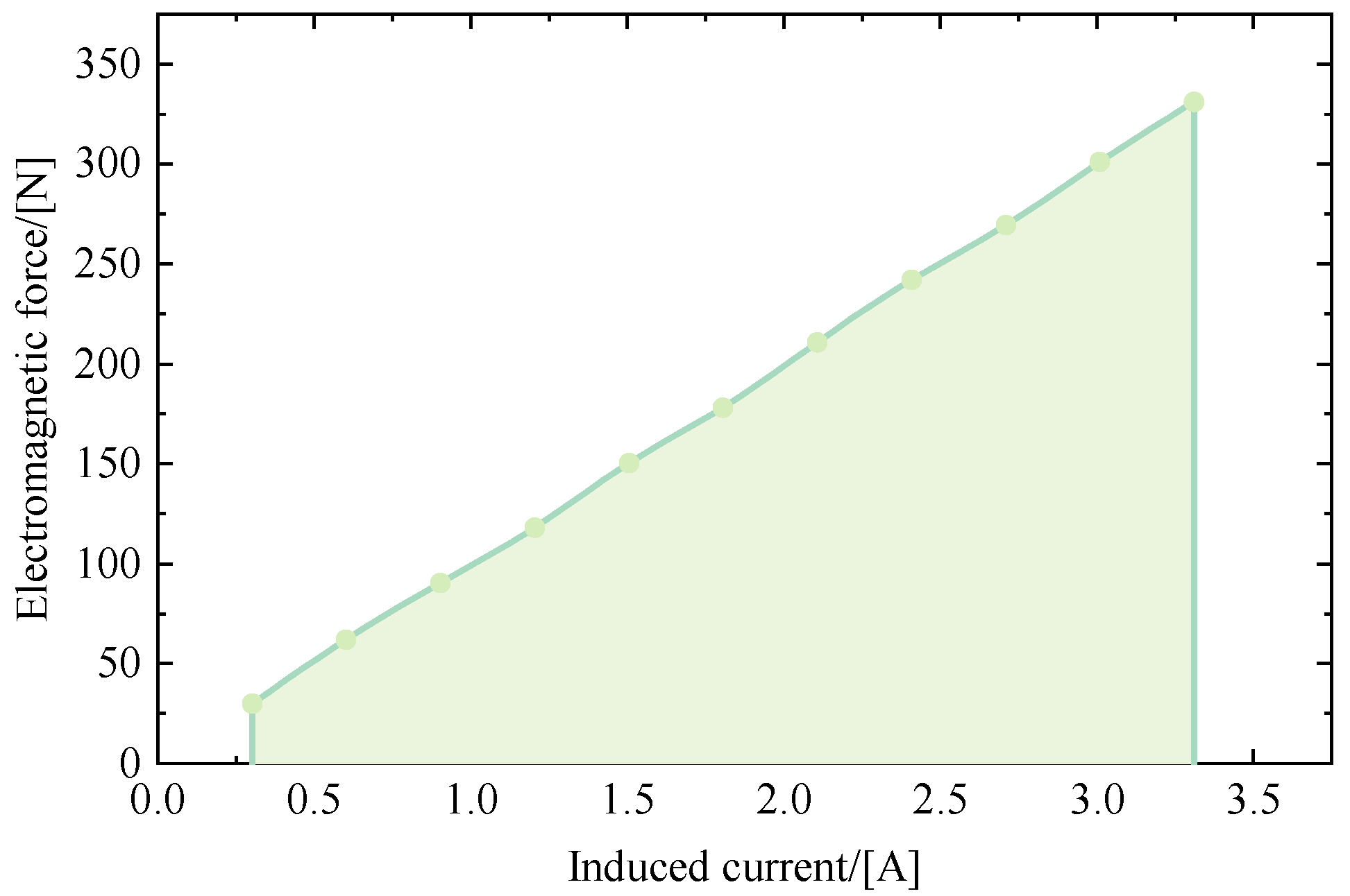
Consequently, when the linear motor moves relative to the stator, the motor generates an induced voltage, while the induced current in the energy recovery circuit makes the linear motor output a speed-dependent electromagnetic force, and the corresponding damping coefficient can be calculated according to the following formula:
Through the bench controller output different frequency sinusoidal wave, by making the linear motor perform a sinusoidal motion, and simultaneously using the oscilloscope to measure the induction voltage generated at both ends of the linear motor, the bench controller records the hydraulic actuator load, which is the output of the linear motor, to feed the energy electromagnetic force. The relationship between linear motor speed and induction voltage is illustrated in
Figure 4, with a calculated value of 81 Vs/m. In addition,
Figure 5 illustrates the correlation between the force generated by the linear motor and the current, which is 100 N/A when the load resistance is 30 Ω.
4. Analysis of Suspension Structure Parameters
In an effort to effectively improve the comprehensive performance of the seat inertial suspension, it is critical to investigate the mechanisms by which structure parameter variations affect the suspension performance. This investigation will provide a foundational basis for future optimization efforts.
In this paper, the root mean squares (RMS) of seat acceleration and seat workspace are used as indicators of suspension vibration suppression performance. The vibration energy input to the seat suspension can be expressed as an integral of the power transient over time:
Assuming that all the energy recovered by the energy harvesting circuit is consumed through the external load resistor, the energy recovered by the suspension is expressed as
:
Therefore, the feed energy efficiency of seat inertial suspension is
:
The electric commercial vehicle is driven at a speed of 72 km/h on a C-class road. Two types of seat inertial suspensions—parallel and series—are numerically simulated and comparatively analyzed. To assess the feasibility of practical applications in engineering, the influence of inertance on suspension performance is examined within the range of 0 to 500 kg, with damping coefficients set at 100 N/m, 300 N/m, 500 N/m, 700 N/m, 900 N/m, and 1100 N/m, respectively, and the seat suspension parameters are shown in
Table 1.
The effects of inertance
b and the damping coefficient
c on suspension performance are first analyzed which the load resistance is 10 Ω. Under different structural configurations, as illustrated in
Figure 6, the inerter and damper play significantly different roles in suppressing seat vibrations. At inertance of less than 150 kg in parallel structure, the seat acceleration decreases as inertance increases, reaching its minimum at 150 kg. Additionally, a smaller damping coefficient results in a greater influence of inertance on seat acceleration. Conversely, when the inertance is under 72.5 kg, a larger damping force is more beneficial for reducing the seat acceleration. When the inertance is greater than 72.5 kg, a reduction in the damping coefficient is more valid in improving seat comfort. However, values above 150 kg may reduce the vibration isolation performance of the seat.
As illustrated in
Figure 7, larger damping coefficient contribute to a reduction in the working space of the seat suspension for both parallel and series structures. The RMS of the suspension working space for the parallel structure reaches its maximum when the inertance is 25 kg. Beyond this point, as the inertance increases past 25 kg, the dynamic travel of the suspension decreases until it exceeds 425 kg, at which point the changes in the suspension working space begin to level off. In contrast, for the series structure, the suspension working space decreases significantly with increasing inertance. Once the inertance surpasses the inflection point on the curve of the suspension working space, its impact on the vibration isolation performance of the seat becomes minimal. A larger damping coefficient results in a later appearance of the inflection point on the suspension working space curve, thereby enhancing the improvement effect. When the inertance exceeds this inflection point, further increases in inertance do not produce a significant change in the effective value of the suspension working space.
The energy harvesting efficiency and power for parallel suspension decrease with an increasing damping coefficient, as shown in
Figure 8 and
Figure 9. However, the inertance exerts a negligible influence on the energy efficiency of the feed. For series structure, they also follow the same trend with respect to variations in suspension workspace. Series structure offers greater potential for vibration energy recovery than a parallel structure. But this comes at the cost of reduced vibration isolation performance of the seat suspension. Therefore, the parallel structure is more effective in balancing vibration suppression and energy recovery performance in the seat suspension system.
During suspension vibration, the damping element dissipates the vibration energy in the form of thermal energy, and the linear motor recovers the vibration energy in the form of electrical energy, which together dissipate the vibration energy of the suspension system. The variation in load resistance can significantly impact the RMS of the energy harvesting efficiency of the suspension. Therefore, the influence of the load resistance on the performance of the seat inertial suspension system is analyzed next. The structural parameters of the parallel and series structure suspensions are shown in
Table 2.
In
Figure 10a, both the two structures’ seat acceleration is impacted differently by the load resistance. Interestingly, when the load resistance is set to 10 Ω, the parallel construction achieves the lowest seat acceleration. However, changes in load resistance have a minimal impact on the overall seat acceleration of the parallel structure. In contrast, an increase in load resistance significantly impairs the seat comfort of the series structure. As depicted in
Figure 10b, the RMS of the suspension working space increases with rising load resistance for both structures. Furthermore, there is little effect on the working space of the suspension when the load resistance exceeds 200 Ω. The dynamic travel of the suspension is also influenced by the increase in load resistance.
As illustrated in
Figure 10c,d, with the variation in load resistance, between 0 and 50 Ω, the suspension structures’ energy recovery ability rises significantly. The peak values for energy harvesting efficiency and power occur at approximately 50 Ω. Beyond this point, as the load resistance continues to increase, both energy harvesting efficiency and power gradually decline and eventually converge. Notably, an increase in load resistance above 500 Ω significantly enhances the series structure’s energy recovery performance.
In both suspension systems, the load resistance of feed energy circuits shows a trend which is in parallel with the RMS related to vibration isolation performance and energy harvesting capabilities. Notably, the load resistance did not raise a conflict between the reduced acceleration of the seat and the increased efficiency of energy recovery. The reduction in inertance is positive for both suspension configurations as it helps to reduce the seat acceleration. Damping in the parallel suspension helps the linear motor to provide greater damping force to suppress seat vibration. As the damping coefficient diminishes, the energy recovery efficiency within the suspension system increases, thereby improving both vibration isolation performance and energy recovery potential. Conversely, in series structure, an elevated damping coefficient enhances the vibration isolation of the seat suspension and assists in reducing the RMS of the suspension workspace. However, large damping dissipates the vibration energy of the series suspension, leading to a reduction in energy recovery efficiency, thus increasing the conflict between the vibration isolation and energy recovery of the seat suspension.
5. Optimized Design of Seat Suspension Structures
The investigation detailed in
Section 4 provides a theoretical framework for identifying appropriate parameter boundaries of the variants associated with suspensions. The NSGA-II algorithm represents an advancement over the conventional genetic algorithm, incorporating enhanced selection and regeneration techniques. In this approach, each individual is categorized based on its dominance and non-dominance relationships. The selection process is then executed to ensure that the algorithm achieves satisfactory results in multi-objective optimization. The optimization objective is shown in Equation (11).
where
J1 and
J2 represent the optimization targets for seat comfort and energy efficiency, respectively.
is the seat acceleration,
is the seat acceleration of conventional suspension.
is the suspension working space,
is the suspension working space of conventional seat suspension. α
1 and α
2 are the weighting coefficients, which are taken as 0.6 and 0.4 in this paper, respectively.
The optimization logic of NSGA-II, a multi-objective optimization algorithm, involves minimizing two objective functions. To enhance the ride comfort of the seat inertial suspension, set
J1 as the sum of the ratios of seat acceleration and suspension working space to passive suspension, respectively, with appropriate weights assigned. Simultaneously, to account for the improvement in suspension energy harvesting efficiency,
J2 is defined as the inverse of the of feed energy efficiency, facilitating the attainment of the optimal solution.
Table 3 outlines the range of optimized parameter values.
This observation suggests the presence of a reciprocal constraint between the two variables, as illustrated in
Figure 11. The light blue denotes the suspension performance area associated with the parallel structure, while the light pink represents the series structure. Both configurations demonstrate a substantial enhancement in overall seat suspension performance when compared to conventional seat suspension system. In order to explore the performance boundaries of suspension dynamics, a single performance metric is analyzed. Among them, the series structure’s seat inertial suspension vibration isolation performance has been improved by up to 22.4%, while the energy recovery efficiency has reached 13.7%. The parallel structure further extends the performance limits of the series suspension, achieving a maximum enhancement of 27.6% in overall vibration isolation performance and an efficiency of peak energy harvesting of 50.3%. The implementation of a parallel structure enhances the performance limits of seat suspension in comparison to a series structure, significantly improving vibration isolation while increasing the feed energy efficiency of the seat inertial suspension. Consequently, the parallel suspension demonstrates superior overall performance.
6. Performance Analysis
The parameters of the suspension system, as determined from the optimal solutions for the parallel structure, are presented in
Table 4. This selection was made after a thorough evaluation of the overall performance of the seat inertial suspension.
The seat inertial suspension was first characterized in the frequency domain. As illustrated in
Figure 12, the seat acceleration gain indicates that, compared to conventional seat suspension systems, the parallel-structured seat inertial suspension significantly reduces seat acceleration when the vibration excitation is below 3.2 Hz, with a notable reduction in the vibration peak by 53.4%. Regarding the suspension working space, as depicted in
Figure 13, the parallel-structured seat inertial suspension shifts the peak frequency of the suspension working space to 1.2 Hz, while the vibration peak decreases by 61.9%. This effectively broadens the vibration isolation range of the seat inertial suspension. The results demonstrate that the low-frequency vibration isolation characteristics of the inerter substantially enhance the overall vibration isolation performance of the seat suspension.
Under the time-domain conditions illustrated in
Figure 14 and
Figure 15, the vibration isolation performance of the seat inertial suspension system demonstrates a significant advantage over conventional seat suspension systems. As indicated in
Table 5, the RMS acceleration of the seat with the parallel-structured inertial suspension is reduced by 36.6%, while the RMS of the suspension working space is decreased by 55.3%. Additionally, the energy harvesting efficiency of the suspension reaches 41.9%, enhancing the vibration isolation performance of the seat suspension while effectively recovering the system’s vibrational energy.


