
The Multiphysics Analysis and Suppression Method for the Electromagnetic Noise of Permanent-Magnet Motors Used in Electric Vehicle

Abstract
1. Introduction
2. Materials and Methods
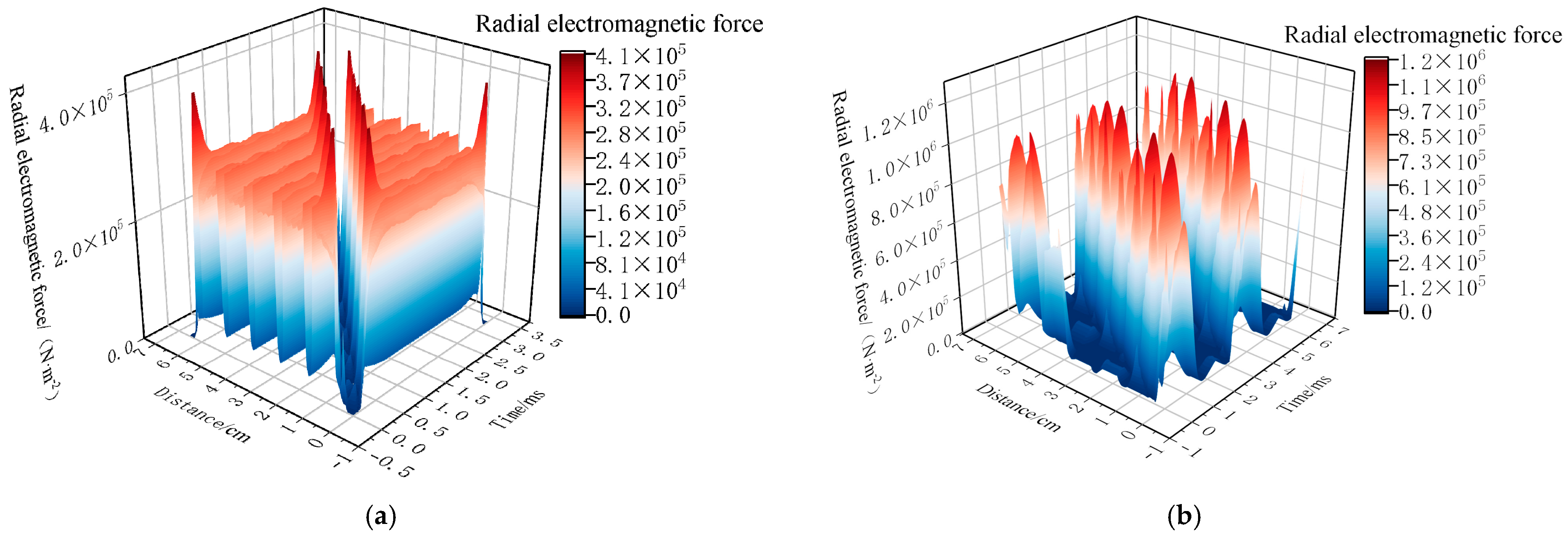
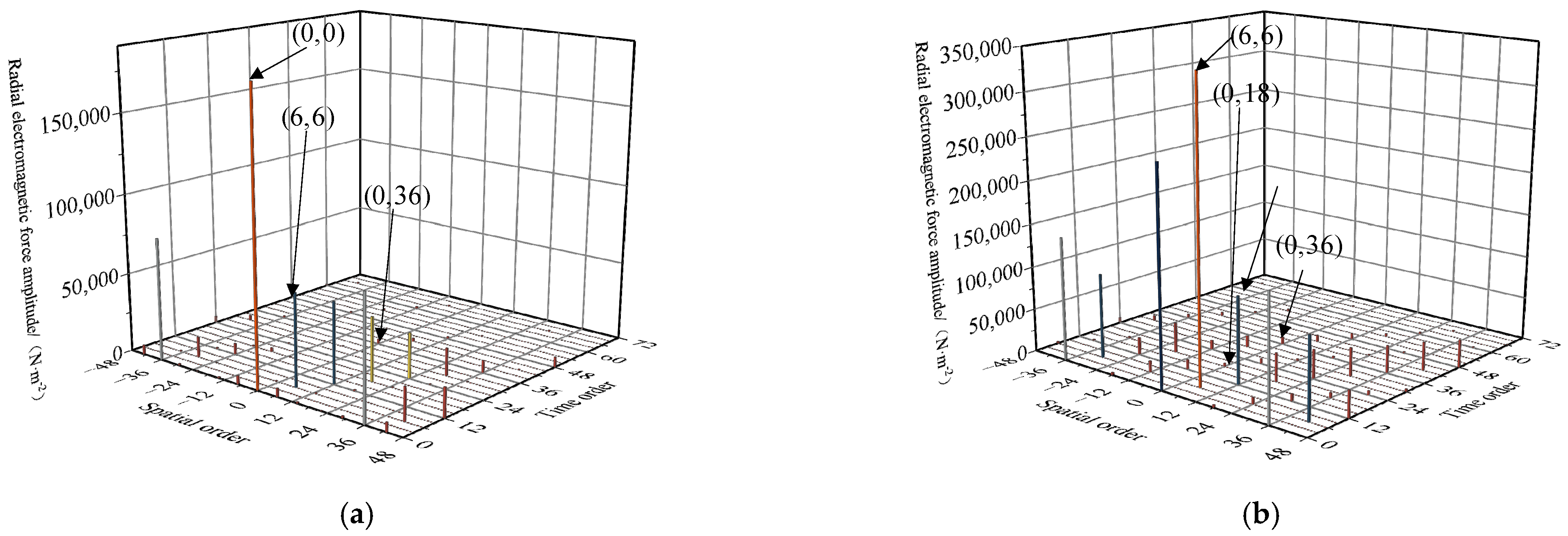
2.1. Electromagnetic Force Analysis
2.1.1. Analytical Method
2.1.2. Finite Element Method
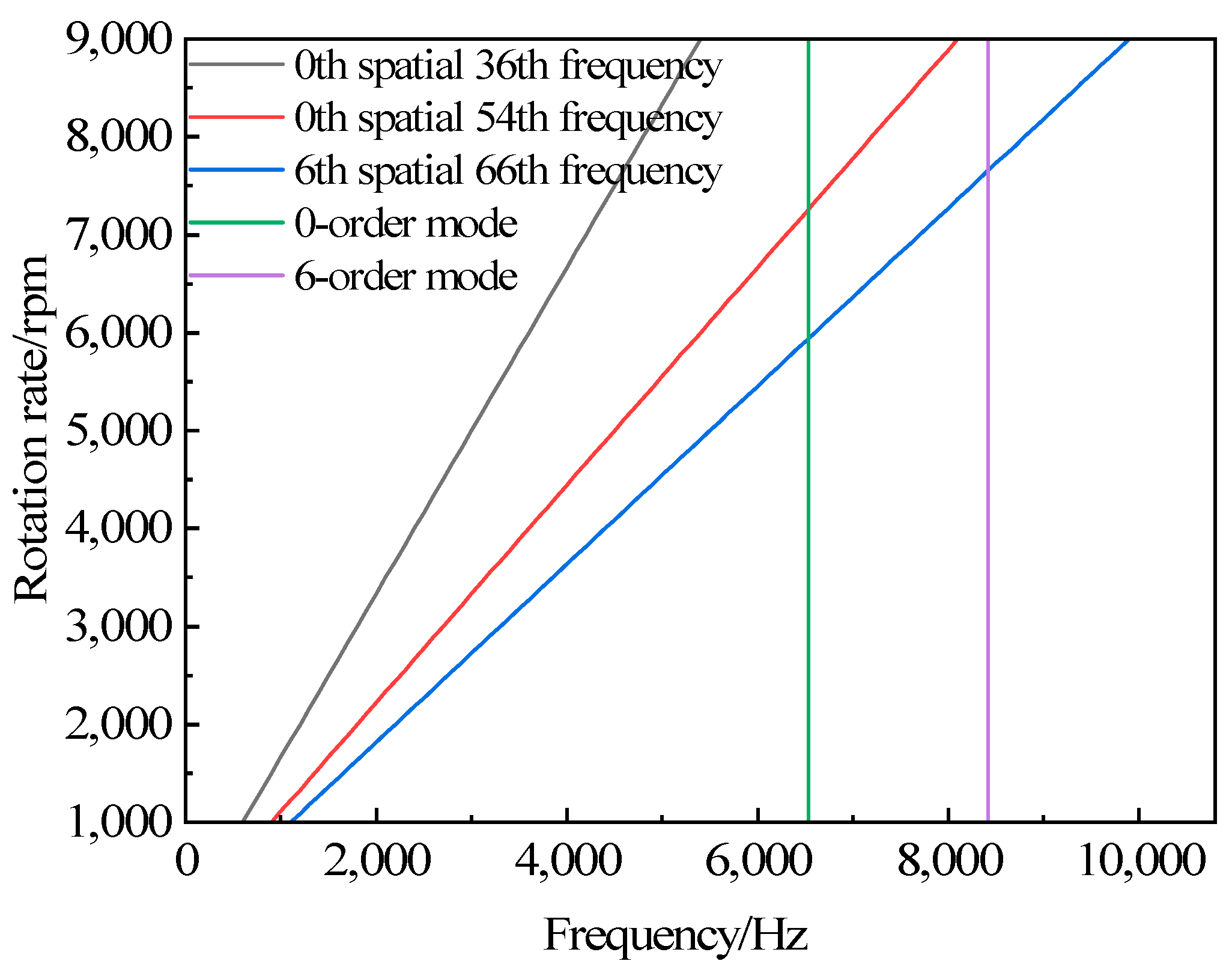
2.2. Modal Analysis
3. Results
4. Discussion
5. Conclusions
Author Contributions
Funding
Data Availability Statement
Conflicts of Interest
References
- Chen, K.; Xu, J. Identification and Analysis of Interior Noise Sources in Pure Electric Vehicles Using OTPA Method. J. Shenyang Univ. Technol. 2022, 41, 78–83. [Google Scholar]
- Chen, M.; Yin, H.; Gao, Y.; Shi, X.; Liu, C. Noise suppression of built-in permanent magnet motor using rotor slotting. J. Chongqing Univ. Technol. (Nat. Sci.) 2022, 36, 109–116. [Google Scholar]
- Dai, J.; Zeng, F.; Xu, Q.; Wang, J. Optimization of Vibration and Noise of Drive Motor Considering Harmonic Current. J. Chongqing Univ. Technol. (Nat. Sci.) 2023, 37, 70–80. [Google Scholar]
- Liu, J. Vibration and Noise Analysis of Permanent Magnet Synchronous Motor Based on Magnetic Pole Offset. Master’s Thesis, Jiangxi University of Science and Technology, Ganzhou, China, 2024. [Google Scholar]
- Gao, F.; Yue, W.; Gao, J.; Xu, H.; Sun, W.; Wu, Y. Electromagnetic optimization and vibration noise suppression of built-in U-shaped permanent magnet motor. J. Harbin Inst. Technol. Priority online publishing. Available online: http://kns.cnki.net/kcms/detail/23.1235.t.20241008.1035.002.html (accessed on 20 January 2025).
- Ma, L.; Chen, X. Optimization of Vibration and Noise of Permanent Magnet Synchronous Motor with Stator Slot Structure. J. Fuzhou Univ. (Nat. Sci.) 2024, 52, 198–206. [Google Scholar]
- Gao, L.; Zheng, H.; Zeng, L.; Pei, R. Evaluation method of noise and vibration used in permanent magnet synchronous motor in electric vehicle. In Proceedings of the IEEE Transportation Electrification Conference and Expo (ITEC), Detroit, MI, USA, 19–21 June 2019; pp. 1–4. [Google Scholar]
- Tian, X.; Li, X.; Lu, Y.; Liu, Y. Multi-objective optimizeddesign of high-density and low-noise IPMSM for electric vehicles. In Proceedings of the 2023 IEEE 6th International Electrical and Energy Conference(CIEEC), Hefei, China, 12–14 May 2023; pp. 4556–4561. [Google Scholar]
- Yang, W.; Wu, F.; Wang, J. Optimization of vibration and noise of permanent magnet synchronous motor based on magnetic domain alignment of permanent magnet. Micro Spec. Mot. 2024, 52, 47–50+57. [Google Scholar]
- Meng, L.; Chen, C.; Shi, Z.; Sun, X. Vibration and Noise Analysis of Permanent Magnet Synchronous Motor Coupled with Magnetic Solid Thermal Multi Physical Fields. Noise Vib. Control 2024, 44, 43–49+117. [Google Scholar]
- Yang, Z.; Wang, S.; Sun, Y.; Cao, H. Vibration reductionby magnetic slot wedge for rotating armature permanent magnet motors. IEEE Trans. Ind. Appl. 2020, 56, 4882–4888. [Google Scholar] [CrossRef]
- Shen, Q.; Cheng, J.; Guo, D.; Yang, T. Analysis and Suppression of Electromagnetic Vibration Noise of Fractional-Slot Concentrated-Windings Interior PMSMs. IEEE Trans. Transp. Electrif. 2024, 10, 5270–5281. [Google Scholar] [CrossRef]
- Fang, H.; Li, D.; Qu, R.; Yan, P. Modulation effect of slotted structure on vibration response in electrical machines. IEEE Trans. Ind. Electron. 2019, 66, 2998–3007. [Google Scholar] [CrossRef]
- Jiang, Z. Research on Electromagnetic Vibration and Noise of Permanent Magnet Motors for Electric Buses. Master’s Thesis, Shenyang University of Technology, Shenyang, China, 2023. [Google Scholar]
- Wang, Y.; Hao, Z.; Zheng, K.; Zheng, X.; Qiu, Y. Electromagnetic noise analysis of permanent magnet synchronous motor based on multi-directional electromagnetic force. J. Zhejiang Univ. (Eng. Ed.) 2020, 54, 2286–2293+2404. [Google Scholar]
- Lin, F.; Zuo, S.; Wu, X.; Wu, S.; Mao, J. Identification of noise sources in permanent magnet synchronous motors based on order analysis. J. Agric. Eng. 2016, 32, 69–76. [Google Scholar]
- Lin, F.; Zuo, S.; Mao, Y.; Wu, S.; Deng, W. Semi analytical model of electromagnetic vibration and noise of permanent magnet synchronous motor considering current harmonics. J. Electr. Eng. 2017, 32, 24–31. [Google Scholar]
- Chen, P.; Yin, H.; Zhang, X.; Shi, L.; Wang, Y. Multiphysics simulation and optimization of electromagnetic vibration noise of embedded permanent magnet motor. Automot. Technol. 2020, 12, 25–29. [Google Scholar]
- Ma, C.; Zuo, S.; Sun, Q.; Meng, S. Analysis of Order Characteristics of Electromagnetic Noise of Permanent Magnet Synchronous Motor Considering Time Harmonic Current. Vib. Impulse 2014, 33, 108–113+125. [Google Scholar]
- Zuo, S.; Liu, X.; Yu, M.; Wu, X.; Zhang, G. Numerical prediction and analysis of electromagnetic vibration of permanent magnet synchronous motor. J. Electr. Eng. 2017, 32, 159–167. [Google Scholar]
- Li, G.; Yin, H.; Sun, Y.; Zhang, Z.; Bi, X.; Hu, W. Multiphysics simulation analysis of permanent magnet motors for vehicles with different pole slots. J. Hebei Univ. Sci. Technol. Priority online publishing. Available online: http://kns.cnki.net/kcms/detail/13.1225.TS.20241122.1456.018.html (accessed on 20 January 2025).


| Radial Electromagnetic Force | Amplitude | Spatial Order | Frequency Order |
|---|---|---|---|
| n2 | n1 | |||||||||||
|---|---|---|---|---|---|---|---|---|---|---|---|---|
| 1 | 3 | 5 | 7 | 9 | 11 | 13 | 15 | 17 | 19 | 21 | 23 | |
| 1 | 0,0 6,6 | 6,6 | / | / | (6,30) | (6,30) (0,36) | (0,36) (6,42) | (6,42) | / | / | (6,66) | (6,66) (0,72) |
| 3 | 6,6 | 0,0 | 6,6 | (6,30) | (0,36) | (6,42) | (6,30) | (0,36) | (6,42) | (6,66) | (0,72) | (6,78) |
| 5 | / | 6,6 | 0,0 (6,30) | 6,6 (0,36) | (6,42) | / | / | (6,30) | (0,36) (6,66) | (6,42) (0,72) | (6,78) | / |
| 7 | / | (6,30) | 6,6 (0,36) | 0,0 (6,42) | 6,6 | / | / | (6/66) | (6,30) (0.72) | (0,36) (6,78) | (6,42) | / |
| 9 | (6,30) | (0,36) | (6,42) | 6,6 | 0,0 | 6,6 | (6,66) | (0,72) | (6,78) | (6,30) | (0,36) | (6,42) |
| 11 | (6,30) (0,36) | (6,42) | / | / | 6,6 | 0,0 (6,66) | 6,6 (0,72) | (6,78) | / | / | (6,30) | (0,36) |
| 13 | (0,36) (6,42) | (6,30) | / | / | (6,66) | 6,6 (0,72) | 0,0 (6,78) | 6,6 | / | / | / | (6,30) |
| 15 | (6,42) | (0,36) | (6,30) | (6,66) | (0,72) | (6,78) | 6,6 | 0,0 | 6,6 | / | / | / |
| 17 | / | (6,42) | (0,36) (6,66) | (6,30) (0,72) | (6,78) | / | / | 6,6 | 0,0 | 6,6 | / | / |
| 19 | / | (6,66) | (6,42) (0,72) | (0,36) (6,78) | (6,30) | / | / | / | 6,6 | 0,0 | 6,6 | / |
| 21 | (6,66) | (0,72) | (6,78) | (6,42) | (0,36) | (6,30) | / | / | / | 6,6 | 0,0 | 6,6 |
| 23 | (6,66) (0,72) | (6,78) | / | / | (6,42) | (0,36) | (6,30) | / | / | / | 6,6 | 0,0 |
| v | n | |||||||||||
|---|---|---|---|---|---|---|---|---|---|---|---|---|
| 1 | 3 | 5 | 7 | 9 | 11 | 13 | 15 | 17 | 19 | 21 | 23 | |
| 1 | 0,0 6,6 | 6,6 | / | / | (6,30) | (6,30) (0,36) | (0,36) (6,42) | (6,42) | / | / | (6,66) | (6,66) (0,72) |
| −5 | / | 6,12 | (6,12) 0,18 | (0,18) 6,24 | (6,24) | / | / | (6,48) | (6,48) (0,54) | (0,54) (6,60) | (6,60) | / |
| 7 | / | (6,12) | 6,12 (0,18) | 0,18 (6,24) | 6,24 | / | / | (6,48) | (6,48) (0,54) | (0,54) (6,60) | (6,60) | / |
| −11 | (0,0) (6,6) | (6,6) | / | / | 6,30 | (6,30) 0,36 | (0,36) 6,42 | (6,42) | / | / | (6,66) | (0,72) |
| 13 | (0,0) | (6,6) | / | / | (6,30) | 6,30 (0,36) | 0,36 (6,42) | 6,42 | / | / | / | (6,66) |
| −17 | / | (6,12) | (6,12) (0,18) | (0,18) (6,24) | (6,24) | / | / | 6,48 | 0,54 | 6,60 | / | / |
| 19 | / | (6,12) | (6,12) (0,18) | (0,18) (6,24) | (6,24) | / | / | / | 6,48 | 0,54 | 6,60 | / |
| −23 | (0,0) (6,6) | (6,6) | / | / | (6,30) | (0,36) | (6,42) | / | / | / | 6,66 | 0,72 |
| Parameter | Value | Unit |
|---|---|---|
| Rated power | 30 | kW |
| Rated voltage | 220 | V |
| Rated speed | 3000 | rpm |
| Maximum speed | 9000 | rpm |
| Parameter | Value | Unit |
|---|---|---|
| Number of slots | 36 | / |
| Outer diameter of the stator | 190 | mm |
| Inner diameter of the stator | 125 | mm |
| Air-gap length | 0.6 | mm |
| Core length | 100 | mm |
| The number of conductors per slot | 128 | / |
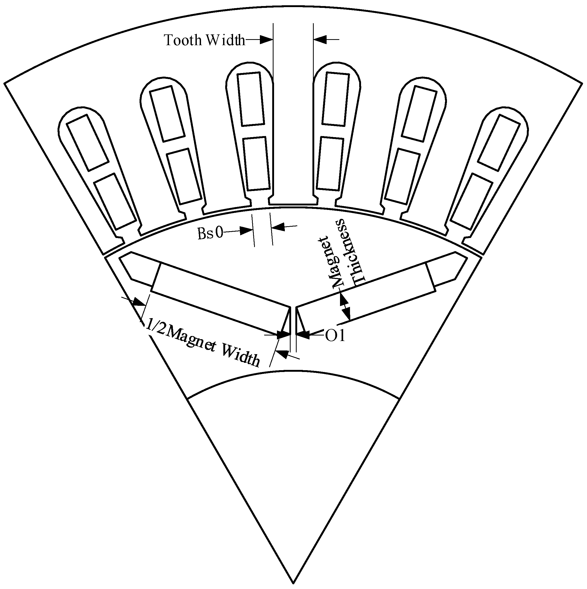
| Width of the stator teeth | 6.6 | mm |
| Width of the stator slot opening | 3.0 | mm |
| Modal Order | Stator | Stator with Casing | Modal Order | Stator | Stator with Casing |
|---|---|---|---|---|---|
| 0 |  |  | 4 |  | 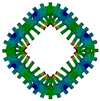 |
| 6323.3 Hz | 6539.3 Hz | 2505.7 Hz | 5028.5 Hz | ||
| 2 |  | 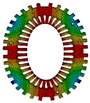 | 5 |  | 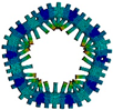 |
| 522.3 Hz | 1181.8 Hz | 3715.5 Hz | 6725.2 Hz | ||
| 3 |  |  | 6 |  | 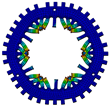 |
| 1400.3 Hz | 3027.9 Hz | 7306.8 Hz | 8415 Hz |
Disclaimer/Publisher’s Note: The statements, opinions and data contained in all publications are solely those of the individual author(s) and contributor(s) and not of MDPI and/or the editor(s). MDPI and/or the editor(s) disclaim responsibility for any injury to people or property resulting from any ideas, methods, instructions or products referred to in the content. |
© 2025 by the authors. Published by MDPI on behalf of the World Electric Vehicle Association. Licensee MDPI, Basel, Switzerland. This article is an open access article distributed under the terms and conditions of the Creative Commons Attribution (CC BY) license (https://creativecommons.org/licenses/by/4.0/).
Share and Cite
Dong, J.; Yin, H.; Li, G.; Wang, X.; Luo, M. The Multiphysics Analysis and Suppression Method for the Electromagnetic Noise of Permanent-Magnet Motors Used in Electric Vehicle. World Electr. Veh. J. 2025, 16, 136. https://doi.org/10.3390/wevj16030136
Dong J, Yin H, Li G, Wang X, Luo M. The Multiphysics Analysis and Suppression Method for the Electromagnetic Noise of Permanent-Magnet Motors Used in Electric Vehicle. World Electric Vehicle Journal. 2025; 16(3):136. https://doi.org/10.3390/wevj16030136
Chicago/Turabian StyleDong, Junhong, Hongbin Yin, Guohao Li, Xiaojun Wang, and Mingyang Luo. 2025. "The Multiphysics Analysis and Suppression Method for the Electromagnetic Noise of Permanent-Magnet Motors Used in Electric Vehicle" World Electric Vehicle Journal 16, no. 3: 136. https://doi.org/10.3390/wevj16030136
APA StyleDong, J., Yin, H., Li, G., Wang, X., & Luo, M. (2025). The Multiphysics Analysis and Suppression Method for the Electromagnetic Noise of Permanent-Magnet Motors Used in Electric Vehicle. World Electric Vehicle Journal, 16(3), 136. https://doi.org/10.3390/wevj16030136