Article

FPGA Implementation of Battery State-of-Charge Estimation Using Extended Kalman Filter and Dynamic Sampling

Department of System Semiconductor Engineering, Sangmyung University, Cheonan-si 31066, Republic of Korea
*
Author to whom correspondence should be addressed.
World Electr. Veh. J. 2025, 16(10), 587; https://doi.org/10.3390/wevj16100587
Submission received: 25 August 2025 / Revised: 5 October 2025 / Accepted: 19 October 2025 / Published: 20 October 2025

Abstract

The rapid increase in the adoption of electric vehicles (EVs) has highlighted issues related to the safety and efficiency of lithium-ion batteries. This study implemented a hardware module to effectively estimate the state of charge (SOC), which is a core element of the battery management system (BMS), using an extended Kalman filter (EKF)-based approach. A method to reduce the power consumption during hardware design through adjustments to the sampling period according to the SOC range was proposed. The root mean square error was obtained as below 0.75, with only 2455 samples out of the 700,000 measurements, achieving a reduction of 99.65%. Following the evaluation of the accuracy of the software model, the results were compared through hardware implementation. Consequently, the performance was verified via synthesis using a DE2-115 FPGA board from Terasic in Taiwan.

1. Introduction

In recent years, owing to the increased awareness regarding the severity of climate change, the adoption of electric vehicles (EVs) has rapidly increased [1]. However, with the increased adoption of EVs, battery safety issues, particularly fire incidents involving lithium-ion batteries, have emerged as significant concerns. Lithium-ion batteries are widely used as the primary energy source in electric vehicles owing to their high energy density, long lifespan, and low self-discharge characteristics. However, improper charging and discharging can pose risks of ignition and explosion of these batteries [2]. To address these battery safety issues and ensure the efficient and safe operation of lithium-ion batteries, the importance of battery management systems (BMSs) has been emphasized. A BMS is a crucial system that monitors the state of a battery, preventing and managing damage caused by overcharging and over-discharging [3,4].
The state of charge (SOC) of a battery indicates its remaining usable capacity and is a key element of a BMS [5,6]. An accurate SOC estimation can enhance the performance and stability of electric vehicles, such as improving their driving range and fuel efficiency [7]. There are various methods for estimating the SOC. The current integration method calculates the SOC by integrating the current used during charging or discharging with the initial SOC value of the battery. Although this facilitates real-time SOC estimation, it accumulates sensor errors [8]. The open-circuit voltage (OCV)–SOC method estimates the SOC based on the relationship between the OCV and the SOC of the battery. However, because this method requires measurements when the cell is stabilized, a certain amount of time is required for the cell to stabilize. This renders real-time estimation impossible [9]. Recently, the estimation of SOC using artificial intelligence techniques such as deep learning and neural networks has been studied [10]. By learning complex patterns through large-scale data training, these methods can exhibit excellent performance in handling nonlinearity and multidimensional data [11]. However, they require a significant amount of data and training time and have drawbacks such as difficulty in real-time implementation and slower processing speeds [12]. An extended Kalman filter (EKF)-based SOC estimation technique was proposed to overcome the limitations of the current integration and OCV–SOC methods [13,14,15]. A nonlinear system can be approximated as a linear time-varying (LTV) system through linearization at each time step. Subsequently, the Kalman filter is applied to estimate the states of this linearized system, and the EKF is used for SOC estimation of the actual nonlinear system [16]. The EKF can estimate SOC by utilizing the battery model and real-time measurement data, and it effectively estimates SOC under various conditions [17].
As modern electric devices such as electric vehicles become more complex, the functional and safety requirements for BMS have increased, leading to a corresponding increase in software complexity [18,19]. To achieve high-performance and low-power BMS, it is necessary to integrate the traditional MCU-centered BMS system with hardware modules. The three types of battery information that can be measured in real time online by the BMS are voltage, current, and temperature [20], and these are dynamically changing data. As far as we have researched, there is currently no hardware design specifically for battery SOC estimation based on these three types of data. Therefore, this paper proposes a hardware design applying the EKF based on the OCV-SOC method, utilizing real-time measurement data of current and terminal voltage according to SOC capacity. Additionally, we propose an SOC estimation system that reduces power consumption by adjusting the current measurement intervals. For battery-powered devices, low power consumption is of critical importance. Accordingly, minimizing operating time and utilizing hardware optimized for the algorithm improve practical applicability, which constitutes a key distinguishing feature of this work.
The remainder of this paper is organized as follows: Section 2 presents the battery model and the EKF algorithm. It details the software model with the algorithm used to change the sampling period according to the SOC interval. Section 3 discusses the EKF hardware design using fixed-point arithmetic and synthesizing an FPGA board. Section 4 discusses potential applications. Finally, Section 5 presents our conclusions.

2. Materials and Methods

2.1. First-Order Equivalent Circuit

Various models are utilized to describe battery operation, with the main models including the equivalent circuit model (ECM), data-driven models, physics-based models, and the finite element model (FEM). The ECM represents the voltage characteristics of a battery through circuit components, while data-driven models employ techniques such as neural networks or support vector machines to model the battery as a black box [21]. Physics-based models focus on explaining the electrochemical processes within the battery, and FEM is used to analyze the 3D heterogeneity of a cell’s thermal performance. However, FEM and data-driven methods are rarely applied in real-time within embedded systems for electric vehicles due to their high computational cost. Common ECM models include the R i n t model, the Thevenin model, Partnership for a New Generation of Vehicles, and the general nonlinear model [22,23,24].
In this paper, the ECM is employed to estimate the capacity of lithium-ion batteries [25,26]. The primary ECM has a single value for the current I b and terminal voltage V t when no load is connected. Further, it exhibits nonlinear operating characteristics owing to the electrochemical reactions inside the battery [27,28]. In ECM, the resistor R i typically represents self-discharge, while the capacitor or voltage source represents the battery’s OCV. RC pairs with different time constants represent the diffusion processes in the electrolyte and porous electrodes, as well as charge transfer and double-layer effects at the electrodes [29].
We briefly review a first-order ECM and its characteristic equations [25,26,27,28,29]. Figure 1 shows a first-order ECM, where V t ,   I b ,     R i ,   and V R C   are the terminal voltage, battery current, internal resistance, and RC ladder, respectively. Further, I b indicates the battery charge and discharge current, which is the sum of the currents flowing through R d and C d . The nonlinear model V R C   was linearized and sampled as a discrete-state space equation (Equation (1)), and is expressed as Equation (2) [25,26,27,28,29].
I b t = C d d V R C t d t + V R C t R d ,
V R C k = 1 Δ t R d C d V R C k 1 + I b k 1 Δ t C d ,
The SOC is the percentage of battery capacity remaining from the total battery capacity. It can be expressed as Equation (3) using the initial SOC value and the integrated battery current during battery charging and discharging. The sampled equation for the discrete-time state-space equation after linearization is obtained as [25,26,27,28,29]
S O C t = S O C 0 0 t I b t C b d t ,
S O C k = S O C k 1 = I b k 1 Δ t C b ,
The terminal voltage ( V t ) is described above, and the state equation of the nonlinear model is expressed as follows [25,26,27,28,29]:
V t k = V O C k V R C k = R i I b ( k ) ,
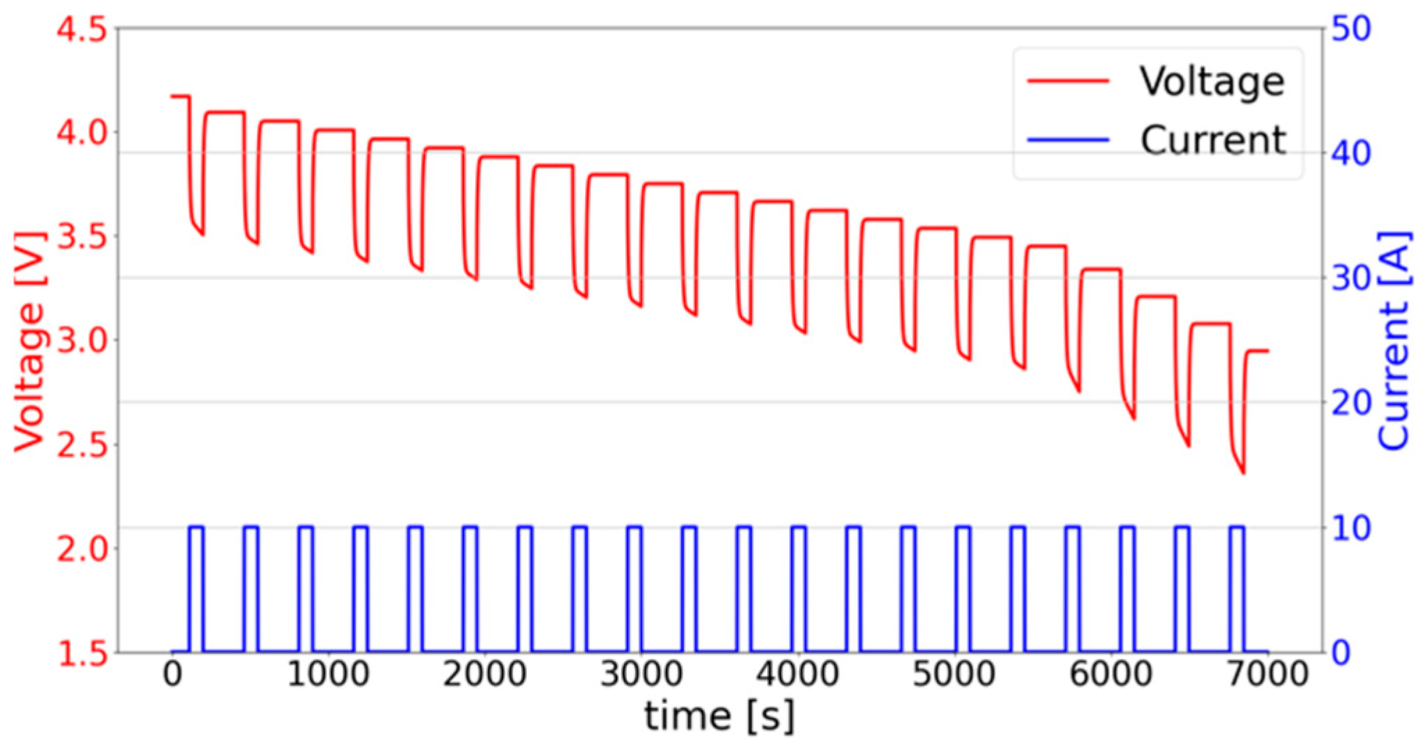
The battery model used in this study was INR 21700-50E (Samsung, Suwon, Republic of Korea). The specifications are presented in Table 1. Figure 2 illustrates the battery voltage and current obtained from the single pulse discharge test based on Table 1.
The terminal voltage V t can be calculated using the state-space equation (Equation (5)) [2]. This equation provides a key element in modeling the change in V t , which is crucial for understanding the dynamic characteristics of the system. Current I b was measured using a single-pulse current discharge experiment [27]. This experimental method was performed by repeating the discharge and rest operations at 5% intervals to change the battery state from a charge cut-off voltage to a discharge cut-off voltage. The value of I b was determined using this method. Based on the above experimental data, the software and hardware models were implemented [30].
The battery parameters used in this study are listed in Table 2. These battery parameters play an important role in setting the state-space equations of the EKF algorithm.

2.2. EKF Algorithm

We briefly review the EKF algorithm [2,31,32]. The EKF is a recursive filter used to estimate nonlinear states from noisy measurements. The EKF algorithm comprises prediction and update phases. In the prediction phase, the current state and input values are used to predict the next state and error covariance. During the update phase, the predicted state is updated based on the current measurement values. A discrete-time model was used as a mathematical model of the battery to estimate the SOC. The basic state-space equations of the EKF are expressed as follows [2,31,32]:
x k = A x k 1 + B u k 1 + w k 1 ,  
y k = H x k + D u k + v k
where x k ,   u k ,   y k ,   w k , and v k represent the state variables, input variables, output variables, process noise, and measurement noise, respectively. In Figure 3, the state variables x k represent the SOC and V R C . The input variable u k is the externally provided input to the system, which is the current I b . The output variable y k is a measurable variable from the system and is the terminal voltage V t . Further, the process noise w k affects the state changes, and measurement noise v k occurs when the output variable is measured. In addition, A and B are the system matrices, and H and D are the output matrices.
During the charging and discharging of battery cells, the SOC exhibits nonlinear behavior. Therefore, this study employed the EKF, which linearized these nonlinear characteristics, to estimate the SOC [33]. The system matrices A and B in Figure 3 are expressed as Equation (8) [2,31,32]. Further, the output matrices H and D are expressed as Equation (9) [2,31,32]. The system matrix A represents the linearized values when the current state of the SOC changes to the next state, whereas matrix B indicates the impact of the charging and discharging currents on the SOC changes. Further, the output matrix H represents the linearized relationship between the SOC and voltage, whereas matrix D represents the internal resistance of the battery.
A = 1 0 0 1 Δ t R d C d ,   B = Δ t C b Δ t C d ,
H = V O C S O C S O C 1 ,   D = R i ,
Q = 10 4 0 0 10 4 ,   R = 10 4 ,
Equations (8) and (9) were derived from the sampled equations of the discrete state-space representation of the first-order ECM in Figure 1. The means of the system and measurement noises in Equations (6) and (7), respectively, were 0. Further, their variances followed a normal distribution with a variance of 10 4 . Consequently, Q and R in Equation (10) were selected accordingly.
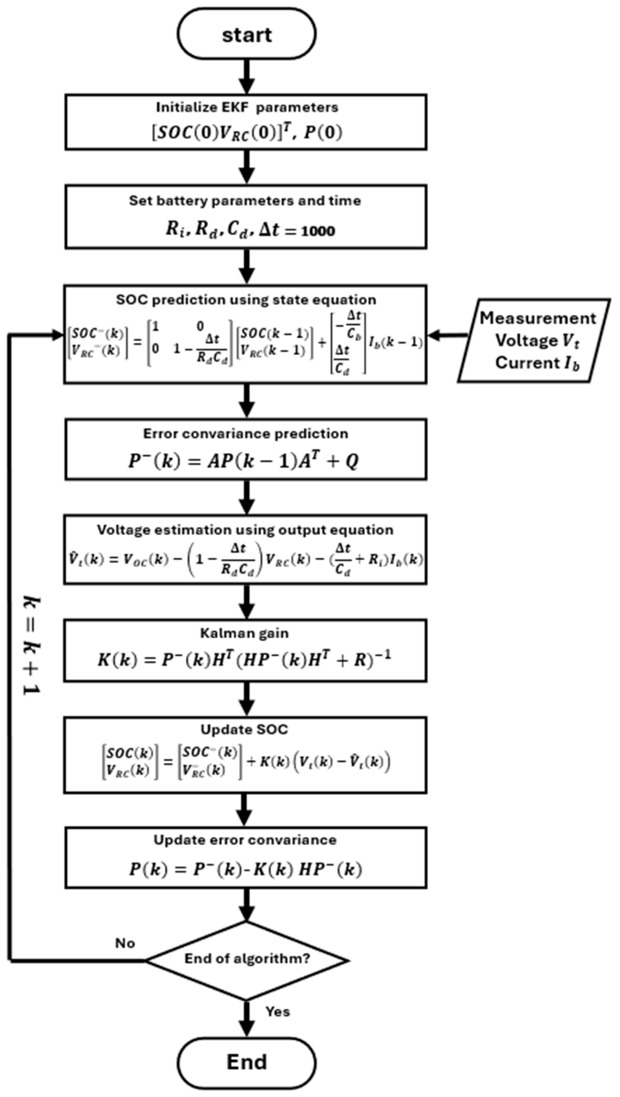
The EKF algorithm for estimating the battery SOC is shown in Figure 3. After setting the initial values of the state variable, SOC, V R C , and error covariance, P, the battery parameters were set. The state equation matrix obtained using Equations (2) and (4) is expressed as follows [2,31,32]:
S O C k V R C k = 1 0 0 1 Δ t R d C d S O C k 1 V R C k 1 + Δ t C b Δ t C d I b k 1
The state variables SOC and V R C were calculated using the estimated value of the terminal voltage as the input [2,31,32].
V ^ t k = V O C k 1 Δ t R d C d V R C k Δ t C d + R i I b k
S O C k V R C k = S O C k V R C k + K k V t k V ^ t k
The EKF estimates the SOC value by repeating the following process. Figure 4a,b show the estimated graphs for different temperatures. Figure 4c shows a graph of the SOC discharging at 25 °C. The standard SOC graph represents the SOC calculated via the measurement unit. Further, the EKF graph represents the SOC calculated using the EKF algorithm, as shown in Figure 3. SOC was estimated using the parameters at 25 °C from Figure 4c and Table 2. By varying the parameter values according to the temperature, the SOC could be estimated in real time.

2.3. Proposed SOC Estimation Using Dynamic Sampling

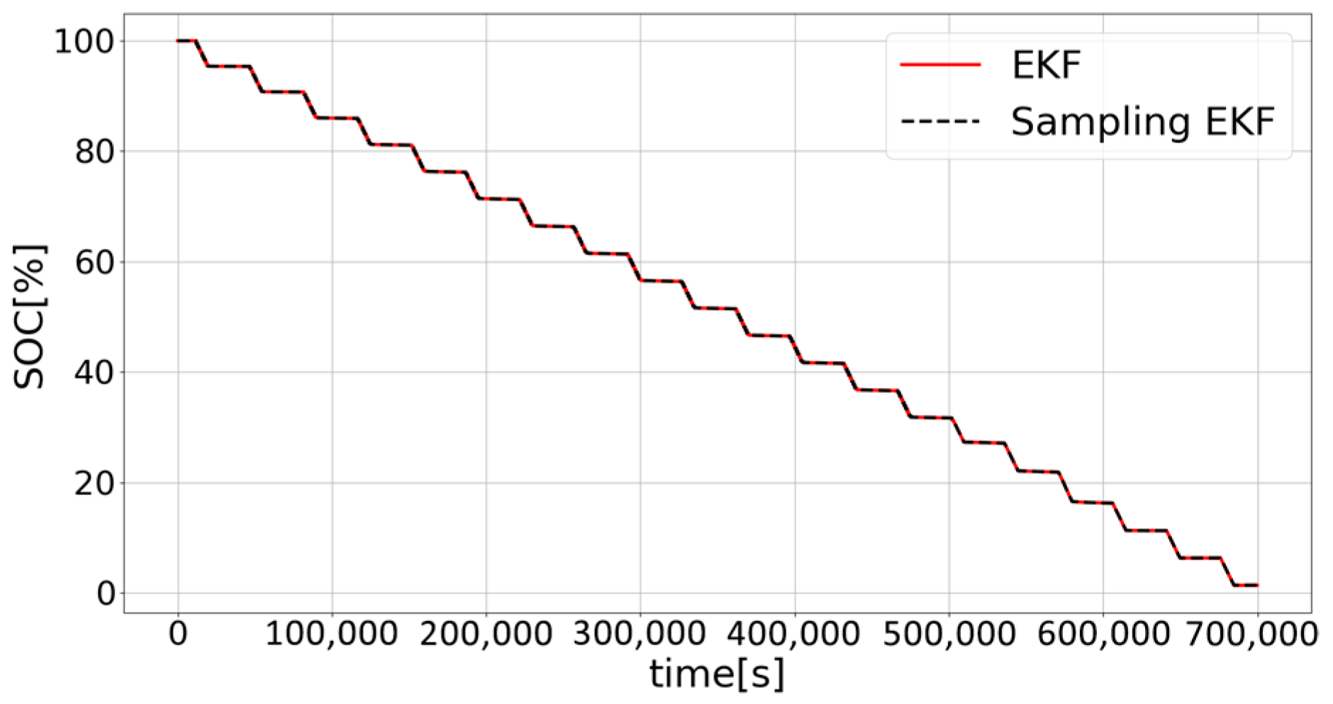
In this study, a sampling technique was proposed for efficient SOC estimation during hardware implementation. The total time required for the battery used in the aforementioned study to discharge was 700,000 s. The SOC estimation with a sampling time of 1 s is shown in Figure 4c. However, estimating the SOC 700,000 times, once per second, is considered inefficient for hardware implementation. Therefore, a technique that adjusted the sampling time was used. Because the probability of battery damage increased with a lower SOC, the measurement frequency increased in the lower SOC range. Thus, when the SOC discharged from 100% to 30% and from 30% to 0%, the sampling times were set to 1000 and 100 s, respectively, as presented in the algorithm in Figure 5. Figure 5 shows the adjusted sampling times from Figure 3. Figure 6 presents a comparison of the SOC of the proposed and standard EKFs. As is evident, although the number of sampling times was reduced by 99.65% from 700,000 to 2455, the root mean square error (RMSE) remained below 0.75.
The accuracy of the developed software model was evaluated using RMSE. Herein, RMSE was used to verify the accuracy of the SOC estimation by considering the square root of the average of the squared differences between the proposed and standard SOC values [27]. Table 3 presents a comparison of the RMSE of the EKF from Figure 3 with that of the EKF proposed in this study based on the SOC calculated from the measurement unit. Because a lower RMSE value indicates higher accuracy, the proposed EKF method has high accuracy.

2.4. Hardware Design

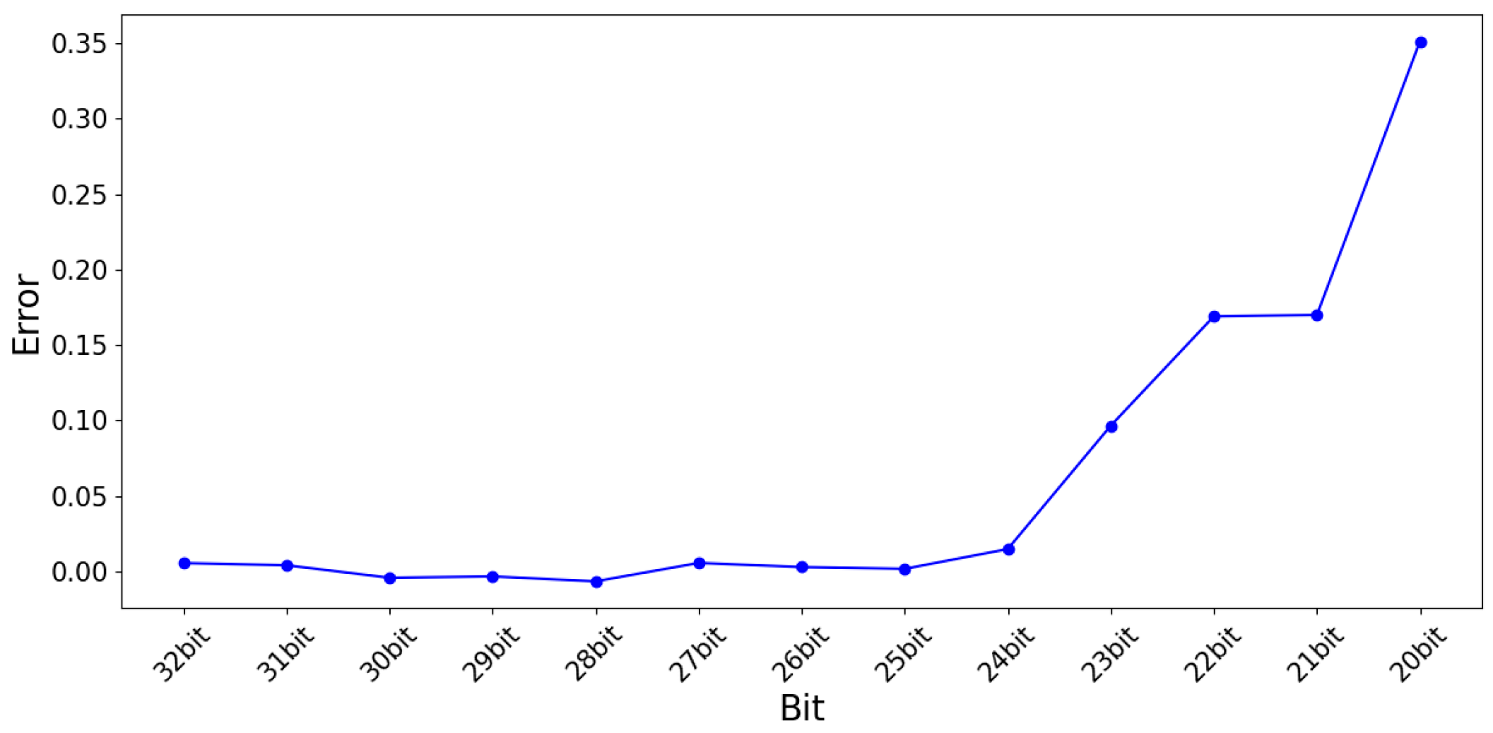
The hardware design was conducted based on a software model. The optimal number of bits was selected using a bit-truncation technique within the range wherein the RMSE value did not increase significantly. Figure 7 shows the RMSE for each bit across the entire dataset. As is evident, the RMSE increased sharply at 23 bits, which decreased the accuracy. Consequently, the variables were selected and designed as 24 bits.
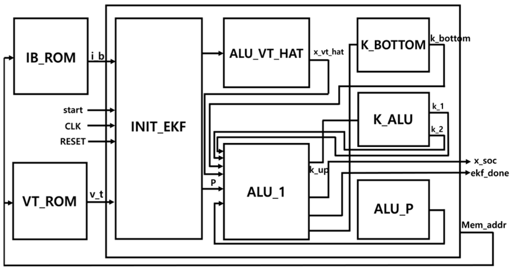
Figure 8 shows a block diagram for implementing the EKF proposed in this study in hardware. This block diagram was designed based on the algorithm shown in Figure 5. The INIT_EKF module sets the initial parameter values. The ALU_VT_HAT module calculates the terminal voltage as the predicted terminal voltage. Further, the K_BOTTOM and K_ALU modules design complex equations by expanding the matrix operations in a scalar manner during the calculation of the Kalman gain.
The equations for estimating and predicting the SOC and V R C , as well as the estimation of the error covariance, as shown in Figure 5, all exhibited the form (A × B) + C. Based on this commonality, the ALU_1 module was designed to efficiently process these equations within a single operation cycle. This approach enhanced the computational speed of the overall system. In addition, by scheduling multiple equations to be processed within a single module, the required hardware resources were reduced, thereby decreasing the hardware area. The matrix equations in Figure 5 were expanded in a scalar manner and then organized. The computational processing speed can be increased by removing the zero elements from the matrix components of Equations (8) and (10).
The ALU_P module optimized the equations in the same manner as ALU_1. This serves to calculate the predicted values of the error covariance. The calculation of the predicted values of the error covariance. The IB_ROM and VT_ROM modules were implemented to store the measured current and terminal voltage in memory, respectively, and load and use the data when needed. By repeating this process 2455 times, the SOC decreased from 100% to 0%. Memory modules were used for the module verification. In an actual system application, the current and terminal voltages are processed using real-time measured values; therefore, memory modules are not used [34].

3. Results

Figure 9 shows a simulation performed with ModelSim-Intel FPGA Edition 20.1 using VerilogHDL. A discharge from 100% to 0% SOC is demonstrated. Using the scheduling method proposed above, it can be observed that the calculations proceed with the timing shown in Figure 9.
Figure 10 presents a comparison of the results of the implemented hardware simulation with those of the software. As is evident, the graphs of the software and hardware matched well. Table 4 compares the hardware implementation results with software to check the results using the RMSE method; the error obtained was 0.001417%. This minor error was caused by the truncation of the least significant bits during bit optimization in the hardware implementation process.
Along with such hardware optimizations, this study also optimized the algorithmic steps for efficient computation during SOC measurement and introduced techniques such as sampling, module scheduling, and time-sharing. These techniques significantly improved computational efficiency, reducing the number of required measurements from 700,000 in a non-optimized hardware implementation to just 2455 when using the proposed EKF algorithm. Additionally, the number of steps required for a single SOC measurement was reduced from 18 to 6 through step optimization and time-sharing techniques. The clock cycles needed for a single SOC measurement were reduced from 159 cycles to 53 cycles, and the total clock cycles for the entire SOC measurement process were reduced from 390,345 cycles to 130,115 cycles, resulting in an approximate 66.7% reduction. Table 5 compares the hardware implementation results of the EKF algorithm without optimizations like time-sharing against the proposed EKF algorithm’s hardware implementation. The results demonstrate that the proposed hardware reduces computation load and latency.
By employing these techniques, hardware resources were conserved, and computation speed was enhanced, contributing to reduced power consumption and heat generation in the hardware. These results indicate that the proposed EKF hardware structure can achieve high performance while maintaining low power consumption.
To verify the performance of the proposed processor, the DE2-115 board (Terasic, Hsinchu, Taiwan) with Cyclone III EP4CE115 (Intel Corporation, Santa Clara, CA, USA) was synthesized using Quartus Prime version 20.1. Table 6 presents the synthesis and implementation results and compares them [35]. Although a different FPGA device was used, making a direct comparison difficult, our proposed hardware achieves approximately 2.5× lower hardware utilization, while operating at a clock frequency about 2.6× slower. Moreover, the computation time required for a single SOC estimation is reduced by a factor of 6.5.
Figure 11 illustrates the process of displaying the SOC discharge values on a 7-segment display using Intel’s DE2-115 FPGA board. The process wherein the SOC decreased from 100% to 0% when using the memory addresses from 0 to 2455 is shown.

4. Discussion

The designed circuit achieves a maximum clock frequency of approximately 38 MHz. Circuit analysis results show that the critical paths are the K_BOTTOM and ALU_P blocks, where two 24-bit multipliers are processed sequentially. By restructuring these blocks into a pipelined architecture to align with the delays of other blocks, the number of cycles required for SoC computation would increase by two; however, the achievable clock frequency is expected to improve.
The performance of the proposed EKF algorithm is influenced by the parameters of the battery model. These parameters can be determined through offline experiments and vary depending on temperature and the current SOC [36]. The proposed hardware uses the average parameter values of the battery model at 25 °C; however, these values are not fixed constants but are set via registers, allowing for adjustments during operation. Therefore, the parameter values of the battery model are measured in advance and stored in memory. Storing parameters under various operating conditions can improve the accuracy of prediction values, though this comes at the cost of increased memory requirements. During operation, the temperature is measured using a temperature sensor, and the corresponding parameters are retrieved from memory based on the calculated SOC estimate. By applying this in real-time to the circuit, the accuracy of SOC estimation can be improved according to the specific conditions.
This study focused on SOC estimation for lithium-ion batteries of EVs. The general EKF algorithm can also be applied to estimate the SOC of lithium polymer batteries [37]. This suggests that the proposed EKF algorithm could be used to estimate the SOC of robots and unmanned aerial vehicles, such as drones [38,39]. In most transport devices, however, battery packs rather than single cells are commonly employed [40]. A BMS must consider not only the SoC estimation of individual cells but also SoC balancing. Even for batteries of the same type, characteristics may differ, and depending on the configuration of the pack, the equivalent impedance and the effective charging/discharging capacity may vary. Therefore, the proposed single-cell model can be adapted for battery packs by modifying the model parameters to reflect the electrical characteristics of the pack.
In next-generation secondary battery technology, lithium metal anodes and solid electrolytes are gaining attention as key technologies for improving energy performance and stability. Particularly in fields like aerospace, where high-efficiency energy sources are required, the selection of an appropriate battery system is crucial. Therefore, if the hardware applying the proposed EKF is integrated into BMS, it is expected to enable the development of high-performance and high-safety battery systems for next-generation secondary battery technologies [41].

5. Conclusions

This study proposed an SOC estimation method using an efficient sampling-technique-based EKF. First, a software model was designed, and its accuracy was measured through its comparisons with the standard SOC. The hardware was implemented and compared with a software model. Based on these steps, the hardware was implemented and synthesized using a DE2-115 board. In this process, as shown in Table 5, we compared the hardware implementation results of the EKF algorithm without optimizations, such as time-sharing, with the proposed hardware implementation of the EKF algorithm. It was confirmed that the proposed hardware reduces computational load and latency. Additionally, we optimized hardware using a sampling technique that achieved a 99.65% reduction over 700,000 measurements. This paper aimed to obtain low-power SOC estimation hardware for EV batteries. The results of this study are expected to contribute to improving the efficiency of BMS. It could be used not only in EVs but also in battery-powered robots and unmanned aerial vehicles. Future research will focus on the SOC estimation of batteries based on an unscented Kalman filter.

Author Contributions

Conceptualization, S.Y. and S.K.; methodology, S.Y., J.J. and E.L.; software, T.J.; validation, T.J., S.Y. and J.J.; writing—original draft preparation, S.Y., J.J. and E.L.; writing—review and editing, S.K.; supervision, S.K. All authors have read and agreed to the published version of the manuscript.

Funding

This research received no external funding.

Data Availability Statement

No new data were created or analyzed in this study. Data sharing is not applicable to this article.

Conflicts of Interest

The authors declare no conflicts of interest.

Abbreviations

The following abbreviations are used in this manuscript:
EVElectric Vehicle
BMSBattery Management System
SOCState of Charge
OCVOpen-Circuit Voltage
EKFExtended Kalman Filter
ECMEquivalent Circuit Model
FEMFinite Element Model
RMSERoot Mean Square Error

References

  1. Lee, S.J.; Son, S.E.; Park, M.H. A study on the Prediction and Effect Analysis of EV Motorization in the Republic of Korea. Innov. Stud. 2017, 12, 117–133. [Google Scholar] [CrossRef]
  2. Yun, J.; Choi, Y.; Lee, J.; Choi, S.; Shin, C. State-of-charge estimation method for lithium-ion batteries using extended Kalman filter with adaptive battery parameters. IEEE Access 2023, 11, 90901–90915. [Google Scholar] [CrossRef]
  3. Gabbar, H.A.; Othman, A.M.; Abdussami, M.R. Review of battery management systems (BMS) development and industrial standards. Technologies 2021, 9, 28. [Google Scholar] [CrossRef]
  4. Pattipati, B.; Pattipati, K.; Christopherson, J.; Namburu, A.; Prokhorov, D.; Qiao, L. Automotive Battery Management Systems. In Proceedings of the IEEE Autotestcon, Salt Lake City, UT, USA, 8–11 September 2008. [Google Scholar] [CrossRef]
  5. Ouyang, Q.; Chen, J.; Zheng, J. State-of-Charge Observer Design for Batteries with Online Model Parameter Identification: A Robust Approach. IEEE Trans. Power Electron. 2020, 35, 5820–5831. [Google Scholar] [CrossRef]
  6. Yoo, S.-H. A Nonlinear Observer Design for Estimating State-of-Charge of Lithium Polymer Battery. J. Korea Inst. Inf. Commun. Eng. 2012, 16, 2187–2193. [Google Scholar] [CrossRef]
  7. Kai, W.; Xiao, F.; Jinbo, P.; Jun, R.; Chongxiong, D.; Liwei, L. State of Charge (SOC) Estimation of Lithium-ion Battery Based on Adaptive Square Root Unscented Kalman Filter. Int. J. Electrochem. Sci. 2020, 15, 9499–9516. [Google Scholar] [CrossRef]
  8. Meng, J.; Ricco, M.; Luo, G.; Swierczynski, M.; Stroe, D.-I.; Store, A.-I. An Overview and Comparison of Online Implementable SOC Estimation Methods for Lithium-Ion Battery. IEEE Trans. Ind. Appl. 2018, 54, 1583–1591. [Google Scholar] [CrossRef]
  9. Jo, S.; Jung, S.-K.; Kim, H.-T. Development of battery monitoring system using the extended Kalman Filter. J. Korea Converg. Soc. 2020, 11, 7–14. [Google Scholar] [CrossRef]
  10. Rivera-Barrera, J.P.; Muñoz-Galeano, N.; Sarmiento-Maldonado, H.O. SoC Estimation for Lithium-ion Batteries: Review and Future Challenges. Electronics 2017, 6, 102. [Google Scholar] [CrossRef]
  11. Zhao, F.; Guo, Y.; Chen, B. A Review of Lithium-Ion Battery State of Charge Estimation Methods Based on Machine Learning. World Electr. Veh. J. 2024, 15, 131. [Google Scholar] [CrossRef]
  12. Liu, K.; Li, K.; Peng, Q.; Zhang, C. A Brief Review on Key Technologies in the Battery Management System of Electric Vehicles. Front. Energy Res. 2019, 14, 669856. [Google Scholar] [CrossRef]
  13. Ryu, K.-S.; Kim, B.; Jang, M.-S. A State-of-charge estimation using extended Kalman filter for battery of electric vehicle. J. Korea Acad.-Ind. Coop. Soc. 2017, 18, 15–23. [Google Scholar] [CrossRef]
  14. Dai, H.; Xu, T.; Zhu, L.; Wei, X.; Sun, Z. Adaptive model parameter identification for large capacity Li-ion batteries on separated time scales. Appl. Energy 2016, 184, 119–131. [Google Scholar] [CrossRef]
  15. Plett, G.L. Extended Kalman filtering for battery management systems of LiPB-based HEV battery packs: Part 1. Background. J. Power Sources 2004, 134, 252–261. [Google Scholar] [CrossRef]
  16. Hu, X.; Li, S.; Peng, H.; Sun, F. Robustness analysis of State-of-Charge estimation methods for two types of Li-ion batteries. J. Power Sources 2012, 217, 209–219. [Google Scholar] [CrossRef]
  17. Peng, S.; Chen, C.; Shi, H.; Yao, Z. State of Charge Estimation of Battery Energy Storage Systems Based on Adaptive Unscented Kalman Filter with a Noise Statistics Estimator. IEEE Access 2017, 5, 13202–13212. [Google Scholar] [CrossRef]
  18. Nijhawan, G.; Annapurna, T. Advanced battery management systems: An in-depth comparative study. In Proceedings of the MATEC Web of Conferences, Telangana, India, 23–25 February 2024. [Google Scholar] [CrossRef]
  19. Krishna, T.N.V.; Kumar, S.V.S.V.P.D.; Srinivasa Rao, S.; Chang, L. Powering the Future: Advanced Battery Management Systems (BMS) for Electric Vehicles. Energies 2024, 17, 3360. [Google Scholar] [CrossRef]
  20. Ahn, J.H. The Present and Future of BMS Research for Safe Energy Society. Korean Inst. Electr. Eng. 2023, 72, 21–27. [Google Scholar]
  21. Yang, S.; Zhou, S.; Hua, Y.; Zhou, X.; Liu, X.; Pan, Y.; Ling, H.; Wu, B. A parameter adaptive method for state of charge estimation of lithium-ion batteries with an improved extended Kalman filter. Sci. Rep. 2021, 11, 5805. [Google Scholar] [CrossRef]
  22. Lee, S.; Kim, J.; Lee, J.; Cho, B.H. State-of-charge and capacity estimation of lithium-ion battery using a new open-circuit voltage versus state-of-charge. J. Power Sources 2008, 185, 1367–1373. [Google Scholar] [CrossRef]
  23. Johnson, V.H. Battery performance models in ADVISOR. J. Power Sources 2002, 110, 321–329. [Google Scholar] [CrossRef]
  24. Battery Test Manual For Plug-In Hybrid Electric Vehicles. Idaho National Laboratory. 2010. Available online: https://inldigitallibrary.inl.gov/sites/sti/sti/4655291.pdf (accessed on 18 October 2025).
  25. Newman, J.; Thomas, K.E.; Hafezi, H.; Wheeler, D.R. Modeling of lithium-ion batteries. J. Power Sources 2003, 119, 838–843. [Google Scholar] [CrossRef]
  26. Jang, K.-W.; Kim, H.-J.; Chung, G.-B. Comparison of Battery Modelings and SOC Estimation Methods. In Proceedings of the KIPE Conference, Pyeongchang, Republic of Korea, 6 July 2010. [Google Scholar]
  27. Park, H.-W.; Lee, J.-H.; Choi, Y.-H.; Son, S.-J.; Yun, J.-J. Analysis of Change in Battery Parameters according to Ambient Temperature and C-rate. J. Korean Inst. Illum. Electr. Install. Eng. 2022, 36, 24–32. [Google Scholar] [CrossRef]
  28. He, H.; Xiong, R.; Fan, J. Evaluation of Lithium-Ion Battery Equivalent Circuit Models for State of Charge Estimation by an Experimental Approach. Energies 2011, 4, 582–598. [Google Scholar] [CrossRef]
  29. Meng, J.; Luo, G.; Ricco, M.; Swierczynski, M.; Stroe, D.-I.; Teodorescu, R. Overview of Lithium-Ion Battery Modeling Methods for State-of-Charge Estimation in Electrical Vehicles. Appl. Sci. 2018, 8, 659. [Google Scholar] [CrossRef]
  30. He, H.; Xiong, R.; Zhang, X.; Sun, F.; Fan, J. State-of-Charge Estimation of the Lithium-Ion Battery Using an Adaptive Extended Kalman Filter Based on an Improved Thevenin Model. IEEE Trans. Veh. Technol. 2011, 60, 1461–1469. [Google Scholar] [CrossRef]
  31. Cui, Z.; Hu, W.; Zhang, G.; Zhang, Z.; Chen, Z. An extended Kalman filter based SOC estimation method for Li-ion battery. Energy Rep. 2022, 8, 81–87. [Google Scholar] [CrossRef]
  32. Jugović, D.; Uskoković, D. A review of recent developments in the synthesis procedures of lithium iron phosphate powders. J. Power Sources 2009, 190, 538–544. [Google Scholar] [CrossRef]
  33. Jwo, D.; Chuang, F.; Weng, T. Adaptive Kalman Filter for Navigation Sensor Fusion. In Sensor Fusion and its Applications; Thomas, C., Ed.; InTech China: Sanghai, China, 2010; pp. 65–90. [Google Scholar]
  34. Klein, R.; Chaturvedi, N.A.; Christensen, J.; Ahmed, J.; Findeisen, R.; Kojic, A. Electrochemical Model Based Observer Design for a Lithium-Ion Battery. IEEE Trans. Control Syst. Technol. 2013, 21, 289–301. [Google Scholar] [CrossRef]
  35. Jemmali, S.; Manaï, B.; Hamouda, M. Pure hardware design and implementation on FPGA of an EKF based accelerated SoC estimator for a lithium-ion battery in electric vehicles. IET Power Electron. 2022, 15, 1004–1015. [Google Scholar] [CrossRef]
  36. He, Z.; Yang, Z.; Cui, X.; Li, E. A Method of State-of-Charge Estimation for EV Power Lithium-Ion Battery Using a Novel Adaptive Extended Kalman Filter. IEEE Trans. Veh. Technol. 2020, 69, 14618–14630. [Google Scholar] [CrossRef]
  37. Schacht-Rodriguez, R.; Ortiz-Torres, G.; García-Beltrán, C.D.; Astorga-Zaragoza, C.M.; Ponsart, J.C.; Theilliol, D. SoC estimation using an Extended Kalman filter for UAV applications. In Proceedings of the 2017 International Conference on Unmanned Aircraft Systems (ICUAS), Miami, FL, USA, 27 July 2017. [Google Scholar] [CrossRef]
  38. Jiao, S.; Zhang, G.; Zhou, M.; Li, G. A Comprehensive Review of Research Hotspots on Battery Management Systems for UAVs. IEEE Access 2023, 11, 84636–84650. [Google Scholar] [CrossRef]
  39. Verstraten, T.; Hosen, M.S.; Berecibar, M.; Vanderborght, B. Selecting Suitable Battery Technologies for Untethered Robot. Energies 2023, 16, 4904. [Google Scholar] [CrossRef]
  40. Omariba, Z.B.; Zhang, L.; Sun, A.D. Review of Battery Cell Balancing Methodologies for Optimizing Battery Pack Performance in Electric Vehicles. IEEE Access 2019, 7, 129335–129352. [Google Scholar] [CrossRef]
  41. Kim, G.-Y.; Lee, H.-J.; Kim, J.-G.; Heo, H.-I. Development Trends of Battery Technologies and Electrical-driven System for Aerospace Missions (PART 1: Development Trends of Lithium based Batteries and Electrified Aircraft Propulsion System). J. Korean Soc. Aeronaut. Space Sci. 2023, 51, 693–708. [Google Scholar] [CrossRef]
Figure 1. First-order equivalent circuit model of the battery.
Wevj 16 00587 g001
Figure 2. Pulse discharge test for battery parameters.
Wevj 16 00587 g002
Figure 3. Battery SOC estimation algorithm using EKF.
Wevj 16 00587 g003
Figure 4. Temperature-dependent SOC estimation graphs: (a) SOC charge, (b) SOC discharge, and (c) 25 °C SOC discharge.
Wevj 16 00587 g004
Figure 5. Proposed EKF algorithm.
Wevj 16 00587 g005
Figure 6. Comparison of standard and proposed EKFs.
Wevj 16 00587 g006
Figure 7. RMSE based on the bit size of the data.
Wevj 16 00587 g007
Figure 8. Block diagram of the EKF hardware.
Wevj 16 00587 g008
Figure 9. Simulation results: from top to bottom, clk: clock signal, n_rst: active low reset signal, ekf_vrc: V R C   values, soc: SOC estimation value, and ekf_done: ekf calculation is done.
Wevj 16 00587 g009
Figure 10. Comparison of software and hardware models.
Wevj 16 00587 g010
Figure 11. Results obtained using the DE2-115 Board.
Wevj 16 00587 g011
Table 1. Specifications of the battery model [2].
ParameterValue
Nominal capacity4900 mAh
Charging cutoff voltage4.2 V
Nominal voltage3.7 V
Discharging cutoff voltage2.5 V
Table 2. Battery parameters based on temperature.
0 °C25 °C45 °C
R i   [ Ω ] 0.0380.0250.024
R d   [ Ω ] 0.0620.0340.031
C d   [ F ] 778217,89023,525
Table 3. Accuracy comparison using RMSE.
ResourceErrors [%]
Standard SOC & EKF0.0166
EKF & Proposed EKF0.7465
Table 4. Hardware and software RMSE measurements.
Errors [%]
Compare H/W and S/W0.001
Table 5. Comparison of the non-optimized H/W and the proposed H/W.
Non-Optimized H/WProposed H/W
Adder3231
Subtractor713
Multiplier6313
Divider32
Clock cycles required for one SOC estimation186
Table 6. Comparison of FPGA implementation results.
Resource[35]
(Zynq-7000 SoC ZC702)
Proposed
(CycloneIII EP4CE115)
LE12,1925770
FF55201919
DSP220 (DSP48E1s)148 (9-bit Multiplier)
Max Frequency100 MHz38.12 MHz
Time of one iteration1.025 μs0.157 μs
Disclaimer/Publisher’s Note: The statements, opinions and data contained in all publications are solely those of the individual author(s) and contributor(s) and not of MDPI and/or the editor(s). MDPI and/or the editor(s) disclaim responsibility for any injury to people or property resulting from any ideas, methods, instructions or products referred to in the content.