Article

Analysis and Improvement of the Dynamic Characteristics of an Electro-Hydrostatic Actuator Based on a Vehicle’s Active Suspension

1
School of Mechanotronics and Vehicle Engineering, Chongqing Jiaotong University, Chongqing 400074, China
2
School of Intelligent Manufacturing Engineering, Chongqing University of Arts and Sciences, Chongqing 402160, China
*
Author to whom correspondence should be addressed.
World Electr. Veh. J. 2025, 16(10), 586; https://doi.org/10.3390/wevj16100586
Submission received: 4 June 2025 / Revised: 18 September 2025 / Accepted: 2 October 2025 / Published: 20 October 2025

Abstract

This study investigates the dynamic characteristics of electro-hydrostatic actuators (EHA), which serve as the core actuating element in vehicle active suspension systems, with the aim of enhancing overall system performance. The purpose of this research is to identify and address the factors limiting EHA dynamic response. Through theoretical analysis from the perspectives of natural frequency properties and power demand, the study reveals that the natural frequency of the motor-pump assembly acts as the primary bottleneck, while insufficient motor output torque represents another major constraint. To overcome these limitations, a method is proposed involving increased maximum motor output torque and reduced rotational inertia of the motor-pump assembly. The feasibility of this approach is validated via frequency domain simulation analysis. Comparative simulations demonstrate that the enhanced EHA system exhibits significantly improved dynamic performance under both step and sinusoidal position commands compared to the baseline system. These findings provide important theoretical insights and practical directions for overcoming actuator performance limitations in vehicle active suspension systems.

1. Introduction

The electro-hydrostatic actuator is the core component for implementing active control in medium- and heavy-duty vehicle active suspension systems. Its actuation performance directly influences the performance of the active suspension system, thus affecting the overall vehicle’s ride comfort and handling stability. For the active suspension system, the electro-hydrostatic servo actuator is required to effectively track position commands during operation—that is, it must possess good position tracking performance. This tracking performance is closely related to the level of its dynamic characteristics.
The EHA is a new type of electromechanical hydraulic integrated actuator [1,2,3,4]. It will include a motor, a pump, a valve, and core components; as such, it will be highly integrated and able to realize on-demand supply and efficient conversion of energy [5,6,7]. Compared with traditional hydraulic actuation systems, it offers advantages including reduced size, lightweight construction, high efficiency, and enhanced reliability, making it a global research focus [8,9,10]. However, EHA systems face two critical technical challenges: poor dynamic characteristics under low-speed and heavy-load conditions and severe motor overheating. Among these, inadequate dynamic performance remains a primary limiting factor for widespread application [11,12]. Therefore, improving the dynamic characteristics of EHAs is crucial. This paper analyzes the dynamic characteristics of EHA systems.
High-speed and high-pressure EHA-FPVMs (Fixed Pump Variable Motor) represent a primary research direction. For instance, the EHA developed by the German company LIEBHERR operates at motor speeds of 16,000 rpm and system pressures of 35 MPa. Similarly, EHAs from the French company Safran-Messier-Bugatti and the UK-based company UTAS-Goodrich achieve motor speeds of 20,000 rpm under the same 35 MPa system pressure. High-speed motors contribute to increased power density, reduced current, and significant mitigation of motor thermal loads. However, the dynamic characteristics of EHA systems under these operational conditions remain insufficiently characterized. For the dynamic characteristics of EHA systems, researchers have conducted a lot of research on EHA systems, mainly from the control point of view. Wang’s team developed a novel control strategy employing a quasi-adaptive sliding variable damping mode controller in cascade with a PID controller, which significantly enhanced system dynamic characteristics [13]. Ren’s team designed and validated a linear position controller for single-rod pump-controlled actuators, meeting requirements for tracking accuracy, stability, and disturbance rejection [14]. Song’s team established a pump-controlled electro-hydrostatic actuation system model integrated with an adaptive sliding mode control scheme, effectively addressing nonlinear time-varying system behaviors [15]. Johan’s team proposed an innovative EHA configuration demonstrating superior efficiency, a comparable dynamic response to conventional valve-controlled systems, and energy regeneration potential through comparative analysis [16]. Agostini’s team experimentally validated a compact EHA mathematical model using crane tests, with analytical results clarifying its energy recovery efficiency relative to valve-controlled architectures [17]. Gao’s team addressed nonlinearities in asymmetric hydraulic cylinders using PID control strategies, with engineering validations confirming method effectiveness [18]. Fu’s team developed an adaptive variable-damping sliding mode controller to resolve system dead zones and parametric uncertainties, demonstrating control scheme reliability through Lyapunov stability analysis and numerical simulations [19]. Gao’s group enhanced control precision for nonlinear time-varying systems by integrating fuzzy logic with BP (Back Propagation) neural networks in their mathematical framework [20]. Wang’s team optimized sliding mode controller parameters via genetic algorithms, achieving notable improvements in dynamic response rates [21]. Sun’s team implemented a global sliding mode controller to strengthen system robustness against parametric variations [22]. Liu’s team devised a particle swarm-optimized sliding mode algorithm targeting position tracking errors induced by external disturbances, with experimental results showing a 30.77% improvement in tracking accuracy [23]. Kou’s team optimized an EHA suspension system using a genetic algorithm, which resulted in a simultaneous improvement in ride comfort by 22.23% and an increase in energy regeneration power by 40.51% [24]. Guo’s team proposed an Internal Model Control strategy for electro-hydraulic actuators, which demonstrated superior performance to PID control in terms of tracking accuracy and disturbance rejection across a range of operating conditions [25]. Kou’s team developed an adaptive Smith predictor control for EHA active suspensions, significantly improving vibration suppression under time-varying delays through a genetic algorithm-optimized compensation [26]. Ni’s team proposed a strict-feedback adaptive control scheme for electro-hydraulic actuators, which significantly enhanced the position tracking accuracy of active suspension systems [27]. In summary, EHA system research encompasses two primary aspects: mitigating external disturbances and enhancing system performance from a control perspective. However, the aforementioned approaches primarily improve tracking error mitigation through single-algorithm control strategies [28,29,30]. This study proposes an actuator-level enhancement strategy for EHA systems, diverging from conventional control-algorithm-dominated methods. By fundamentally improving the physical structure rather than compensating via control, this research provides a more foundational solution that complements existing approaches and opens a new avenue for high-performance active suspension design.
This study analyzes the dynamic characteristics of an Electro-Hydrostatic Actuator (EHA) system based on its current operational state. Investigations into natural frequency characteristics and power demand across system segments reveal key factors influencing EHA dynamic performance. To address these limitations, two primary improvement strategies are proposed: increasing the motor’s maximum output torque and reducing the rotational inertia of the motor-pump unit. Finally, the effectiveness of the proposed improvement method was validated through position tracking characteristics simulation.

2. Dynamic Characteristic Analysis of EHA Subsystem

2.1. Hydraulic Subsystem Dynamic Performance

The EHA functions as a representative pump-controlled actuation system, utilizing a BLDC motor to drive a hydraulic pump that generates fluid flow. This flow governs the output displacement of the actuator, enabling precise motion control. A schematic representation of the EHA system is provided in Figure 1.
A notable characteristic of the EHA is considerable leakage within its hydraulic pump. This includes internal leakage occurring between the two working chambers and external leakage flowing from the high-pressure chamber toward the return port, with the latter representing the dominant leakage path. Nevertheless, given the closed-loop architecture of the EHA, hydraulic fluid from the return port is redirected into the alternate pump chamber via a replenishment circuit. Consequently, when establishing the hydraulic model of the EHA, external leakage is considered equivalent to internal leakage, with leakage induced by pump rotation being neglected.
According to Reference [31], the flow equation of the pump is as follows:
Q f = D ω K i P l
where Q f is the system flow rate, D is the pump displacement, ω is the input angular velocity, K i denotes the aggregate leakage coefficient for the pump, and P l represents the system pressure.
The flow continuity equation defined by the hydraulic actuator is written as follows:
Q f = A x ˙ + V l B P ˙ l + K il P l
where A is the effective piston area, x is the piston output displacement, V 1 is the initial cylinder volume, K il is the cylinder leakage coefficient, and B is the bulk modulus of the hydraulic oil.
The piston force equilibrium equation is
P l A = M x ¨ + K v p x ˙ + F l
where M is the equivalent load on the piston rod and piston mass, K v p is the piston damping coefficient, and F l is the applied external force.
Based on the integration of Equations (1)–(3), the transfer function of the hydraulic subsystem is formulated.
X = A D A 2 + K v p K l k ω V 1 / B s + K l k A 2 + K v p K l k F l s V 1 M / B A 2 + K v p K l k s 2 + V 1 M / B + M C i A 2 + K v p K l k s + 1
where the parameter K l k = K i + K il is defined as the total leakage coefficient in the hydraulic system, the output is the piston displacement X , and the input is the motor angular velocity ω .
The EHA system’s hydrodynamic natural frequency is calculated as follows:
ω n = 1 2 π B ( A 2 + K v p K l k ) M V l
where the parameter ω n is defined as the system’s hydraulic natural frequency.
The open-loop gain of the system is calculated as follows:
K v = A D A 2 + K v p K l k
where K v is the open-loop gain of the system.
Accounting for pump leakage effects, the open-loop gain experiences a reduction. Table 1 summarizes the principal parameters of the EHA hydraulic subsystem. The system exhibits a hydraulic natural frequency above 250 Hz, with an open-loop gain below 2.11 × 10⁻⁴. Theoretical calculations confirm that the hydraulic subsystem does not constitute the dominant constraint on EHA dynamic performance. Leakage occurring in both the pump and actuator cylinder raises the hydraulic natural frequency while simultaneously lowering the system open-loop gain.

2.2. Motor-Pump Subsystem Dynamic Performance

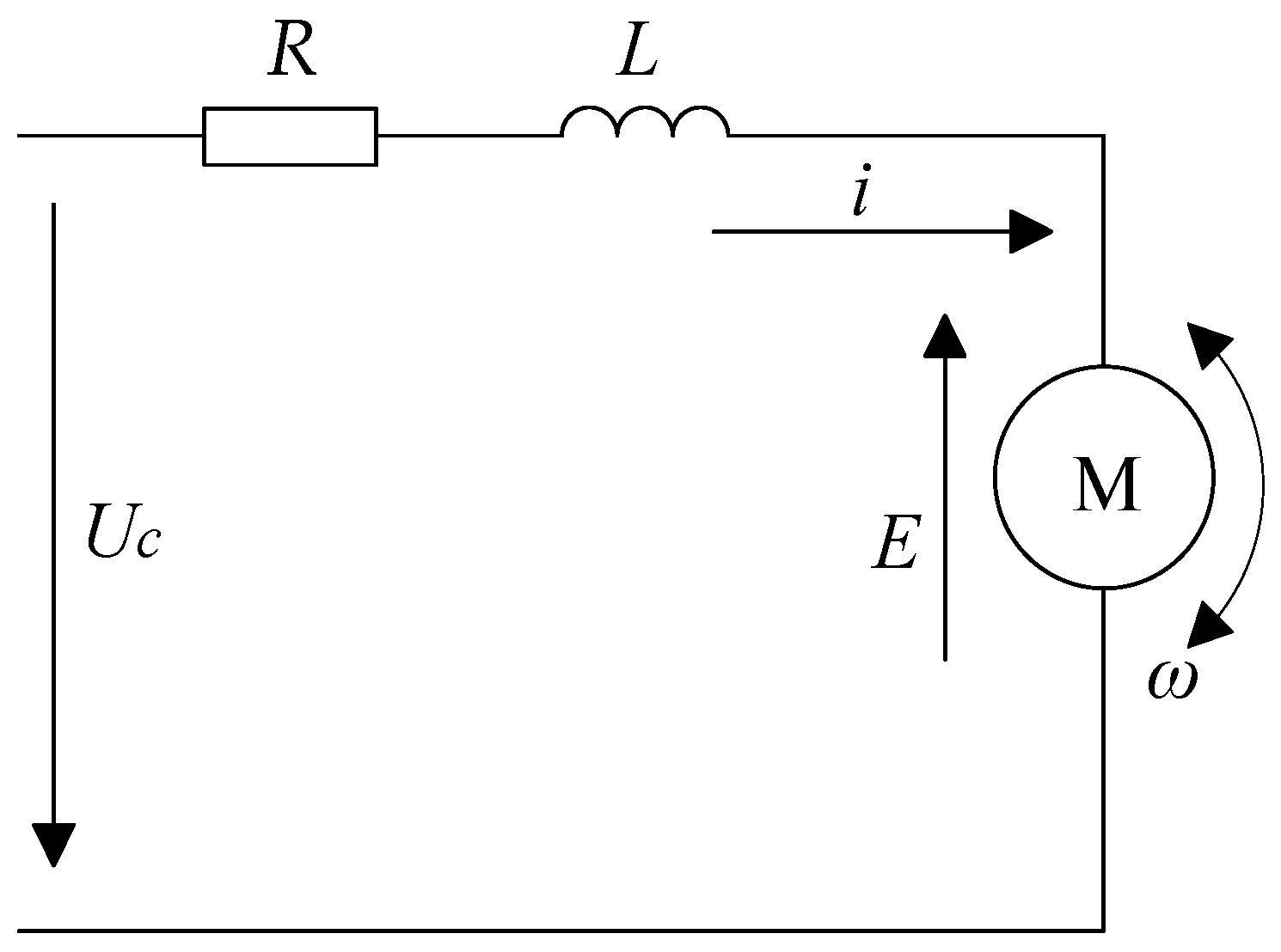
The hydraulic pump in the EHA is powered by a brushless DC motor, the equivalent circuit of which is presented in Figure 2.
The armature current equation for a BLDC motor is
U c = R i + L d i d t + E
where U c is armature voltage, R is the stator winding resistance, i is current, L is stator inductance, and E is the armature back electromotive force.
The equation of the back electromotive is written as follows:
E = K c ω
where K c is the back electromotive coefficient.
The dynamic torque balance equation of the brushless DC motor is calculated as follows:
K t i = J ω ˙ + K v m ω + D P 1
where K t is the motor torque coefficient, J is the moment of inertia, and K v m is the motor damping coefficient.
Based on the mathematical models from Equations (7)–(9), the motor subsystem transfer function is obtained as follows:
ω = K t R K v m + K t K c U c L s + R R K v m + K t K c D P 1 L J R K v m + K t K c s 2 + L K v m + R J R K v m + K t K c s + 1
Therefore, the natural frequency of the EHA system motor is written as follows:
ω m = 1 2 π R K v m + K t K c L J
where the parameter ω m is defined as the EHA system’s motor natural frequency.
Table 2 provides the parameter set for the EHA motor subsystem. The drive unit utilizes a dual-loop strategy regulating current and speed, achieving a no-load natural frequency of 22.6 Hz. When incorporating the pump’s rotational inertia into the system analysis, the resulting motor-pump assembly exhibits a natural frequency of 19.3 Hz, constraining the attainable bandwidth of the velocity control loop. Analytical results confirm that this natural frequency value does not primarily account for the EHA’s limited dynamic response. While the natural frequencies of individual EHA components are not the main constraints on dynamic performance, the motor-pump unit’s natural frequency constitutes the weakest link among all subsystems.

3. Subsystem Load Characteristic Analysis

3.1. Load Characterization Demands in Hydraulic Systems

The frequency response analysis of the actuator cylinder is conducted under the assumption of negligible friction. System evaluation is performed under no-load conditions, with subsequent kinematic and dynamic analysis carried out on the actuator cylinder.
The kinematic equation of the piston is calculated as follows:
v a = a 1 η ( 2 π ) f cos ( 2 π f t )
where v a is the piston velocity; a 1 is 1.5% of the actuator cylinder’s maximum stroke; η is the amplitude attenuation ratio, which at 10 Hz is 0.89125; and f is the test frequency of the system.
The dynamic requirements equation of the actuator is calculated as follows:
T a = M A D a 1 η ( 2 π ) 2 f 2 sin ( 2 π f t )
where the required motor torque for piston motion is represented by T a .
The maximum power requirement equation of the actuator cylinder is calculated as follows:
P a = T a ω = T a v a A D = 1 2 M A D a 1 η 2 2 π f 3
where P a is the power required for piston motion.
Based on the EHA system parameters under 10 Hz operating conditions, the maximum piston velocity corresponds to a motor speed exceeding 1898.4 r/min. The output force of the actuator, when converted to motor inertial torque, attains a minimum value of 0.049 N·m. Furthermore, the peak power demand of the actuator matches the motor’s output power, reaching at least 33.8 W. Theoretical verification establishes that the motor’s power delivery capability adequately supports the actuator’s operational requirements at this frequency.

3.2. Load Characterization Demands in Electromechanical Systems

For simplified frequency domain characterization of the motor, frictional losses in the motor-pump assembly and leakage effects within the hydraulic pump and actuator cylinder are disregarded. The complete motor-pump–actuator system is treated as an idealized configuration.
The kinematic mathematical representation for the motor is calculated as follows:
n = 60 A 2 π D a 1 η ( 2 π ) f cos ( 2 π f t )
where n is the motor speed.
The dynamic equation of the motor is calculated as follows:
T b = J A D a 1 η ( 2 π ) 2 f 2 sin ( 2 π f t )
where T b represents the motor torque necessary for motor-pump motion.
The load characteristic equation of the motor is calculated as follows:
T b A D J ( 2 π ) 2 f 2 a 1 η + n A D ( 2 π f a 1 ) η = 1
The motor power requirement equation is calculated as follows:
P b = T b ω = T b n 2 π 60 = 1 2 J A D a 1 η 2 ( 2 π f ) 3
where P b is the maximum power requirement.
During dynamic characteristic testing, the maximum rotational speed of the motor-pump assembly varies linearly with frequency, while its peak moment of inertia follows a quadratic dependence on frequency. The system’s maximum power demand increases with the cube of the frequency, as mathematically expressed in Equations (15), (16) and (18).
Based on the established EHA parameters, Figure 3 presents the following characteristics across different frequencies: motor speed (a), maximum output torque (b), theoretically computed maximum output power of the motor-pump unit (c), and the corresponding power demand profiles (d).
Under 10 Hz operating conditions, the EHA system attains a minimum motor speed of 1898.4 r/min while maintaining a minimum output torque of 15 N·m. The corresponding power delivery reaches no less than 3.8 kW. Due to system efficiency factors—particularly substantial pump leakage—the measured values for speed, torque, and power consistently surpass theoretical predictions. Analytical findings demonstrate that an EHA prototype equipped with a motor possessing a rated torque of 10 N·m, a maximum speed of 10,000 r/min, and a power capacity of 10 kW achieves an operational bandwidth of approximately 5 Hz. Based on the analysis of the motor-pump load characteristics, the motor output torque is identified as the primary limiting factor for the dynamic performance of the EHA.

4. Dynamic Characteristic Enhancement Methods

Analysis of the system’s natural frequency and load behavior identifies the motor-pump unit’s natural frequency and load characteristics as the dominant limiting factors for frequency response. Dynamic performance can be enhanced through minimization of the motor-pump assembly’s rotational inertia, combined with elevation of the motor’s peak torque capability.

4.1. Reducing Rotational Inertia of Motor-Pump

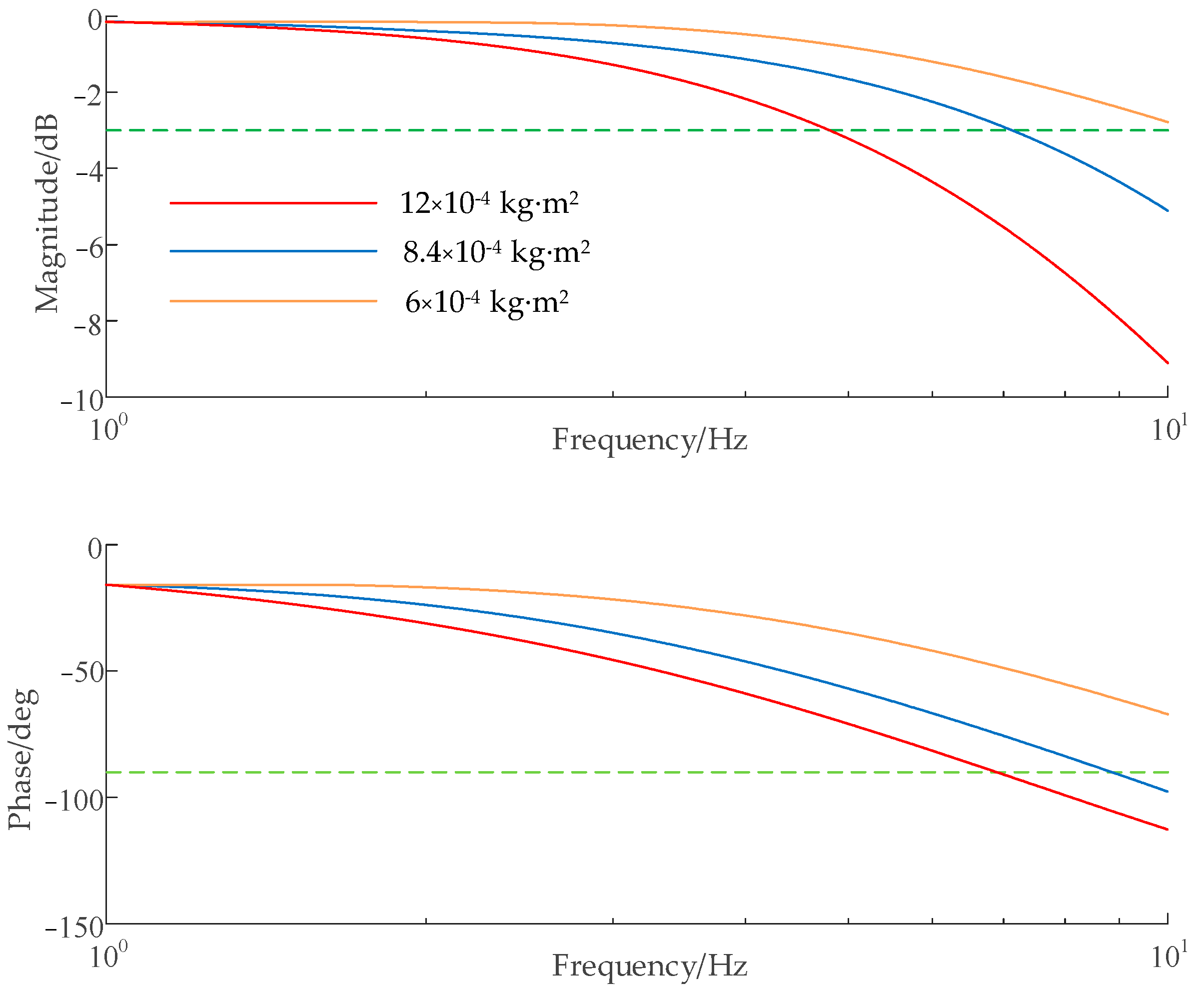
Elevated operational speeds represent a defining characteristic of EHA motor-pump assemblies. Equation (16) indicates that lowering the rotational inertia of this assembly effectively diminishes the inertial load during high-frequency movements. Maintaining constant motor torque output while achieving such inertia reduction permits operation under more demanding frequency conditions. Equation (11) further confirms that inertia reduction contributes to elevated system-wide natural frequency characteristics, thereby enhancing the EHA’s overall dynamic response capability.
Using the established EHA parameters, a Simulink model was constructed for motor-pump rotational inertia optimization. Three inertia configurations were evaluated: the baseline value, along with reductions of 30% and 54%. The simulation outcomes, displayed in Figure 4, demonstrate that a 54% reduction in rotational inertia elevates the system bandwidth from 5 Hz to 10 Hz, markedly improving response rapidity, signal variation tracking, positioning speed, and overall dynamic performance. In Figure 4, the green dashed line in the magnitude-frequency curve represents the −3 dB threshold, while the green dashed line in the phase-frequency curve indicates the −90° threshold.

4.2. Increasing Motor Output Torque

According to Equation (16), fixed rotational inertia conditions permit achieving higher frequency operation through boosted motor torque output. This approach effectively advances the EHA system’s frequency characteristics.
Parameter-based simulations were performed with progressively elevated levels of maximum motor output torque. Three torque configurations were examined: 10 N·m, 15 N·m, and 20 N·m. As illustrated in Figure 5, elevating the maximum torque to 20 N·m expands the system bandwidth from 5 Hz to 10 Hz.
The EHA system performance necessitates enhanced motor capabilities, specifically regarding specific power, operational velocity, output torque, and moment of inertia. Improved power-to-mass characteristics enable overall mass reduction of the system, whereas optimized torque and inertia parameters directly improve dynamic response. These performance criteria collectively impose more advanced specifications on motor design.
Enhancement of the EHA system’s load characteristics is achieved through elevated maximum motor torque and decreased rotational inertia in the motor-pump assembly, with corresponding benefits in dynamic response performance.

5. EHA Simulation Analysis

To validate the effectiveness of the proposed method for improving the dynamic characteristics of the EHA, a simulation model was built in Simulink, as shown in Figure 6.
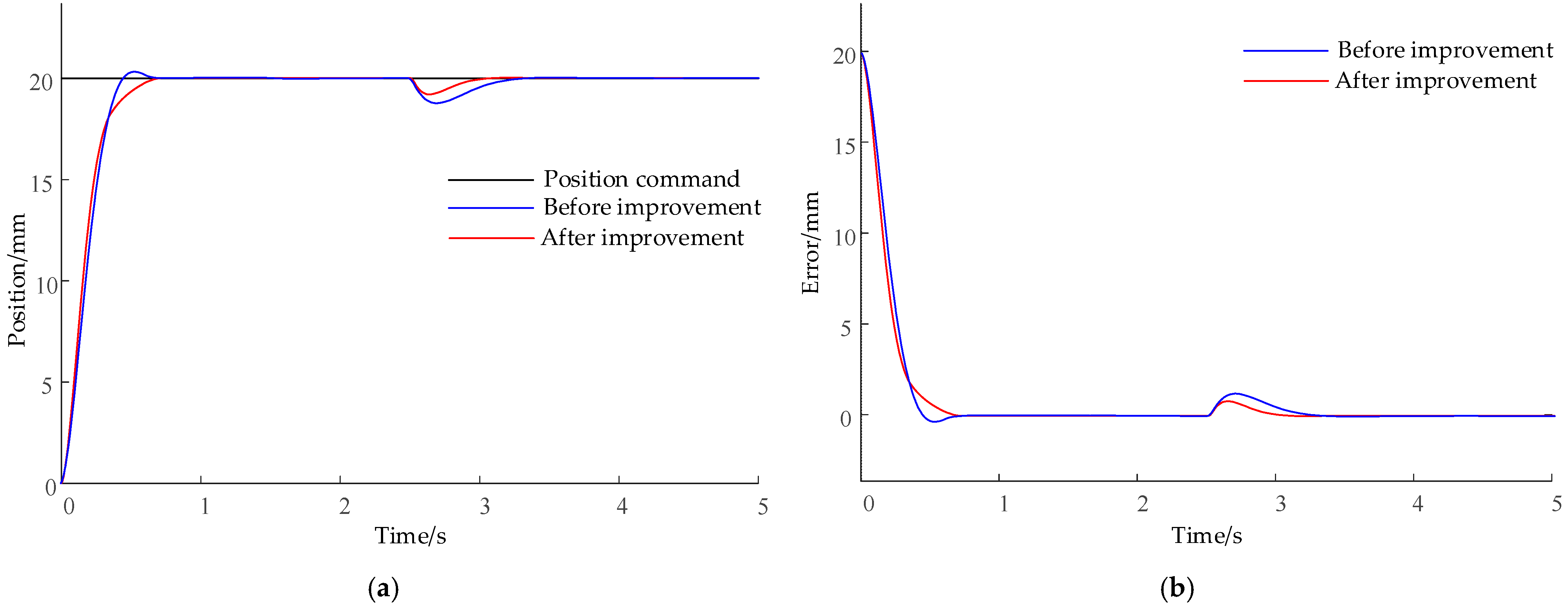
In the step position command simulation, a 20 mm step signal input was applied to the EHA system, and a 5 kN external load disturbance was applied at 2.5 s of operation. The position curve and position tracking error curve were obtained from the simulation, as shown in Figure 7.
As shown in Table 3 and Figure 7a, the rise times of both methods are similar in the 20 mm step simulation. The pre-improvement curve exhibits overshoot, with an overshoot value of 2.3%. In contrast, the post-improvement curve maintains a rapid response while showing almost no overshoot, indicating significantly enhanced dynamic performance. Regarding settling time, the pre-improvement curve requires 0.82 s to stabilize, whereas the post-improvement curve requires only 0.58 s, representing a 29% improvement in response speed. For disturbance rejection, the post-improvement capability is significantly superior. Figure 7b shows that an abrupt error change occurs during the initial tracking phase, but the error is essentially eliminated after system stabilization, indicating that the post-improvement curve offers dual advantages in dynamic regulation and steady-state maintenance.
In the step position command simulation, a 40 mm step signal input was applied to the EHA system, and a 5 kN external load disturbance was applied at 2.5 s of operation. The position curve and position tracking error curve were obtained from the simulation, as shown in Figure 8.
As shown in Table 4 and Figure 8a, the rise times of both methods are similar in the 40 mm step simulation. The pre-improvement curve exhibits overshoot with an overshoot value of 2.1%. In contrast, the post-improvement curve maintains a rapid response while showing almost no overshoot. Regarding settling time, the pre-improvement curve requires 0.85 s to stabilize, whereas the post-improvement curve requires only 0.61 s, representing a 28% improvement in response speed. For disturbance rejection, the post-improvement capability is significantly superior. Figure 8b shows that an abrupt error change occurs during the initial tracking phase, but the error is essentially eliminated after system stabilization, indicating dual advantages of the post-improvement curve in dynamic regulation and steady-state maintenance.
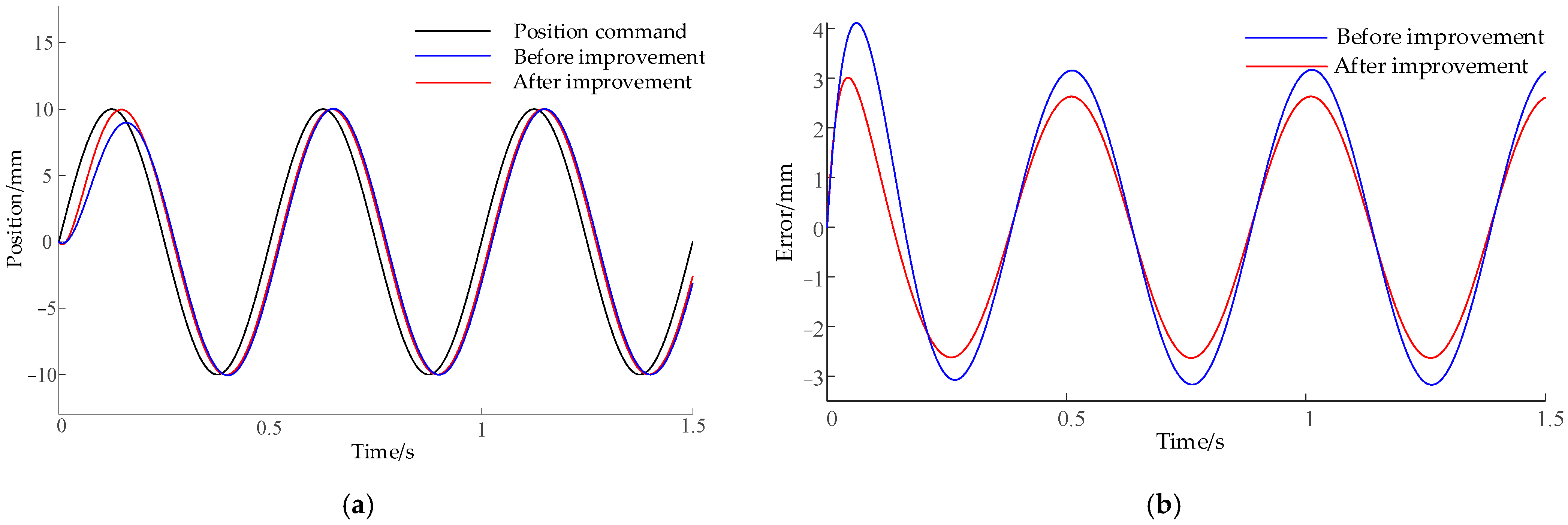
To evaluate the EHA position tracking characteristics, a sinusoidal position command with an amplitude of 10 mm and frequency of 2 Hz was added to the input command. The position tracking characteristics and position tracking error curve were obtained from the simulation, as shown in Figure 9.
As shown in Table 5 and Figure 9, distinct characteristics in displacement tracking between the two methods for periodic position commands are revealed. Figure 9a demonstrates that the post-improvement curve exhibits higher adherence to the position command curve, indicating its enhanced ability to closely follow command variations and superior dynamic response performance. The position tracking error curve in Figure 9b shows that the pre-improvement curve exhibits larger fluctuations, signifying greater deviation from the command value during tracking. Conversely, the post-improvement error curve displays reduced oscillation amplitude and lower overall error levels, with the error peak decreasing from 3.1 mm to 2.6 mm. This demonstrates the clear advantage of the improved method in suppressing tracking errors, enabling more stable convergence of system output toward the command value.

6. Conclusions

This research addresses dynamic characteristic challenges in the electro-hydrostatic actuator (EHA) for vehicle active suspension. Theoretical analysis identifies key factors constraining EHA dynamic performance. Insufficient power delivery capability of the motor-pump assembly constitutes the fundamental limitation, specifically manifested through the effects of motor output torque and rotational inertia.
The following resolution methods are proposed: increasing maximum motor output torque and reducing motor-pump assembly rotational inertia. Frequency domain simulations validate the feasibility of this approach. Comparative analysis demonstrates that the enhanced system achieves faster, smoother step responses along with reduced delay and improved accuracy in sinusoidal position tracking, confirming the effectiveness of the method.
Significantly, this actuator-intrinsic parameter optimization approach offers more fundamental performance enhancement potential than control algorithm refinement alone. The proposed methodology demonstrates considerable transferability to domains requiring high-precision motion control. In aerospace applications, for instance, such actuation enhancements could significantly improve the response accuracy and reliability of aircraft rudders, elevators, and flap systems. Similarly, benefits could extend to robotic manipulators requiring high dynamic precision, industrial automation systems, marine steering mechanisms, and heavy-duty equipment used in construction and mining—all of which share critical requirements for dynamic responsiveness and energy-efficient actuation that align directly with the performance improvements achieved in this study.
Future research will focus on integrated system optimization that combines multi-physics modeling with energy recovery mechanisms to improve sustainability. The incorporation of AI-based control strategies—such as reinforcement learning for real-time adaptive control or deep neural networks for predictive compensation of load disturbances—presents a promising direction for enhancing performance across varied operating conditions. Implementation and validation using full-scale prototypes under realistic working environments will be essential to bridge these advancements toward practical and sustainable applications.

Author Contributions

Conceptualization, P.C. and X.C.; methodology, P.C.; software, P.C.; validation, P.C. and X.C.; formal analysis, P.C.; investigation, X.C.; resources, X.C.; data curation, P.C.; writing—original draft preparation, P.C.; writing—review and editing, P.C.; visualization, P.C.; supervision, P.C.; project administration, X.C. All authors have read and agreed to the published version of the manuscript.

Funding

This research received no external funding.

Data Availability Statement

The original contributions presented in this study are included in the article. Further inquiries can be directed at the corresponding author.

Conflicts of Interest

The author declares no conflicts of interest.

References

  1. Kumar, M. A survey on electro hydrostatic actuator: Architecture and way ahead. Mater. Today Proc. 2021, 45, 6057–6063. [Google Scholar] [CrossRef]
  2. Van Den Bossche, D. The A380 flight control electro-hydrostatic actuators, achievements and lessons learnt. In Proceedings of the ICAC 2006: 25th International Congress of the Aeronautical Sciences, Hamburg, Germany, 3–8 September 2006; pp. 1–8. [Google Scholar]
  3. Moog Inc. Electro Hydrostatic Actuators; Moog Inc.: Elma, NY, USA, 2014. [Google Scholar]
  4. Parker Inc. Control Systems and Actuation Technologies; Parker Inc.: Cleveland, OH, USA, 2014. [Google Scholar]
  5. Li, K.; Wang, S.P. Multidisciplinary modeling method and simulation for electro-hydrostatic actuator. In Proceedings of the ICIEA 2010: 5th IEEE Conference on Industrial Electronics and Applications, Taichung, Taiwan, 15–17 June 2010; pp. 544–548. [Google Scholar]
  6. Huang, X.Y.; Gerada, C.; Goodman, A.; Bradley, K.; Zhang, H.; Fang, Y.T. A Brushless DC motor design for an aircraft electro-hydraulic actuation system. In Proceedings of the IEMDC 2011: 2011 IEEE International Electric machines and Drives Conference, Niagara Falls, ON, Canada, 15–18 May 2011; pp. 1153–1158. [Google Scholar]
  7. Martin, G.; Louis, D. Multidomain high-detailed modeling of an electro-hydrostatic actuator and advanced position control. In Proceedings of the IECON 2012: 38th Annual Conference on IEEE Industrial Electronics Society, Montreal, QC, Canada, 25–28 October 2012; pp. 5463–5470. [Google Scholar]
  8. Wang, J.L.; Zeng, S.K.; Ma, J.M.; Wu, W.W. Research on an integrated methodology of the dynamic performance and reliability evaluation. In Proceedings of the ICRMS’2011 9th International Conference on Reliability, Maintainability and Safety: Safety First, Reliability Primary, Guiyang, China, 12–15 June 2011; pp. 122–128. [Google Scholar]
  9. Hu, X.; Mao, Z.J.; Jiao, Z.X.; Wu, S.; Yu, X.; Li, F.Y. Analysis of the characteristics by modeling and simulation of actuator in flight control system. In Proceedings of the CGNCC 2014, 6th IEEE Chinese Guidance, Navigation and Control Conference, Yantai, China, 8–10 August 2014; pp. 2618–2623. [Google Scholar]
  10. Hu, W.N.; Zhou, L.; Tian, Y.S.; Jiao, Z.X.; Shang, Y.X.; Song, Z.N.; Yan, L. Analysis for the power loss of electro hydrostatic actuator and hydraulic actuator. In Proceedings of the 2015 IEEE International Conference on Advanced Intelligent Mechatronics, Busan, Republic of Korea, 7–11 July 2015; pp. 613–616. [Google Scholar]
  11. Janne, K.; Jouni, M. Stable and high performance energy-efficient motion control of electric load sensing controlled hydraulic manipulators. In Proceedings of the FPMC 2013: Proceedings of the ASME/BATH 2013 Symposium on Fluid Power & Motion Control, Sarasota, FL, USA, 6–9 October 2013; p. V001T01A024. [Google Scholar]
  12. Yasuo, S. Calculation of dynamic overall efficiency of a load sensing hydraulic system by bondgraphs. In Proceedings of the IECON 2000: 26th Annual Conference of the IEEE Electronics Society, Nagoya, Japan, 22–28 October 2000; pp. 1568–1573. [Google Scholar]
  13. Wang, M.K.; Fu, Y.L.; Zhao, J.A.; Yang, R. Novel Variable-Damping Cascade Sliding Mode Control for Electro-Hydrostatic Actuators. J. Beijing Univ. Aeronaut. Astronaut. 2021, 47, 1612–1618. [Google Scholar] [CrossRef]
  14. Ren, G.; Costa, G.K.; Sepehri, N. Position control of an electro-hydrostatic asymmetric actuator operating in all quadrants. Mechatronics 2020, 67, 102344. [Google Scholar] [CrossRef]
  15. Song, B.; Lee, D.; Park, S.Y.; Baek, Y.S. Design and Performa nce of Nonlinear Control for an Electro-Hydraulic Actuator Considering a Wearabl e Robot. Processes 2019, 7, 389. [Google Scholar] [CrossRef]
  16. Johan, J.K.; Kjeld, E.M.; Rygaard, H.M. Novel Conce pt for Electro-Hydrostatic Actuators for Motion Control of Hydraulic Manipulators. Energies 2021, 14, 6566. [Google Scholar] [CrossRef]
  17. Agostini, T.; De Negri, V.; Minav, T.; Pietola, M. Effect of Energy Rec overy on Efficiency in Electro-Hydrostatic Closed System for Differential Actuator. Actuators 2020, 9, 12. [Google Scholar] [CrossRef]
  18. Gao, B.; Shi, L. The nonlinearity simulation study on electrical hydrostatic actuator. In Proceedings of the 2012 2nd International Conference on Consumer Electronics, Communications and Networks (CECNet), Yichang, China, 21–23 April 2012. [Google Scholar]
  19. Fu, Y.; Li, Y.; Wang, M.; Lin, Z.; Zhu, D. Adaptive Variable-Damping Sliding Mode Control for Electro-Hydrostatic Actuators. J. Beijing Inst. Technol. 2021, 41, 1171–1178. [Google Scholar]
  20. Gao, Q.; Jin, Y.; Wang, L.; Hou, Y.; Ji, L. Modeling Study of Pump-Controlled Cylinder Electro-Hydraulic Position Servo System. Acta Armamentarii 2011, 32, 950–956. [Google Scholar]
  21. Wang, Y.P.; Guo, C.; Chen, Y.; Xie, W. Simulation of Genetic Optimization Control for EHA in Aircraft Hydraulic Servo Systems. Comput. Simul. 2016, 33, 53–57+62. [Google Scholar] [CrossRef]
  22. Sun, L.; Zheng, C.S. Research on Global Sliding Mode Control for Hydraulic Actuators. Manuf. Autom. 2014, 36, 19–22. [Google Scholar]
  23. Liu, L.T.; Jiao, H.B. Research on Position Tracking of Electro-Hydrostatic Actuators Using Sliding Mode Control. Chin. J. Constr. Mach. 2020, 18, 430–435. [Google Scholar]
  24. Kou, F.; Du, J.; Wang, Z.; Li, D.; Xu, J. Nonlinear Modeling and Coordinate Optimization of a Semi-Active Energy Regenerative Suspension with an Electro-Hydraulic Actuator. Algorithms 2018, 11, 12. [Google Scholar] [CrossRef]
  25. Guo, Q.; Zhao, D.; Zhao, X.; Li, Z.; Wu, L.; Shi, X. Research on Position Control of Active Suspension Electro-Hydraulic Servo Actuator Based on Internal Model Control. Trans. Chin. Soc. Agric. Mach. 2020, 51, 394–404. [Google Scholar]
  26. Kou, F.; Zhang, H.; Xu, J.; Tian, H.; Peng, X. Adaptive Smith feedback time-delay control for electro-hydrostatic hydraulic active suspension. J. Vib. Meas. Diagn. 2022, 42, 864–870+1030. [Google Scholar]
  27. Ni, T.; Lv, B.; Zhang, P.H.; Zhao, Z.; Sun, X.; Zhang, H. Research on Control Strategy of Electro-Hydraulic Servo Actuator Based on Strict Feedback Model. China Mech. Eng. 2024, 35, 928–937+949. [Google Scholar]
  28. Kalyoncu, M.; Haydim, M. Mathematical modelling and fuzzy logic based position control of an electrohydraulic servosystem with internal leakage. J. Mechatron. 2009, 19, 847–858. [Google Scholar] [CrossRef]
  29. Loan, U.; Adrian, T.; Andrei, H.; Silvia, B. New stabilization and tracking control laws for electrohydraulic servomechanisms. Eur. J. Control 2013, 19, 65–70. [Google Scholar]
  30. Zhang, Q.; Li, B.Q. Feedback linearization PID control for electrohydrostatic actuator. In Proceedings of the AIMSEC 2011: 2nd International Conference on Artificial Intelligence, Management Science and Electronic Commerce, Dengfeng, China, 8–10 August 2011; pp. 358–361. [Google Scholar]
  31. Ji, H. Hydraulic and Pneumatic Transmission and Control Edited; Huazhong University of Science: Wuhan, China, 2014. [Google Scholar]
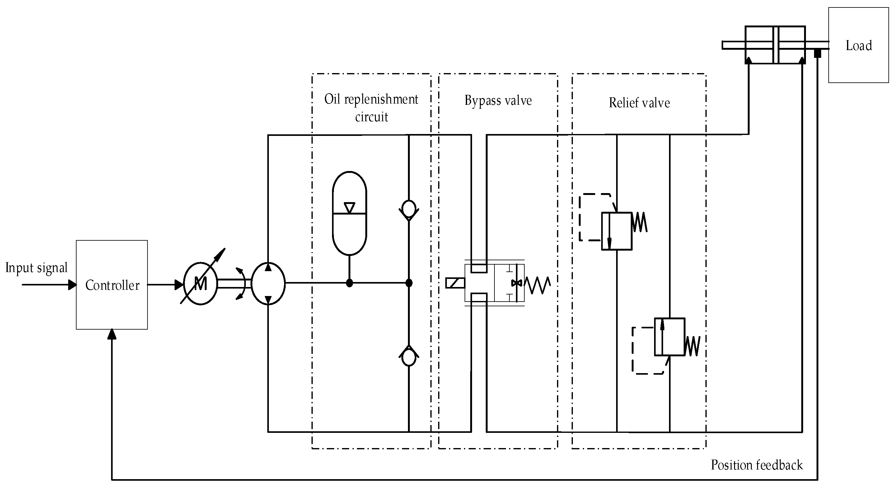
Figure 1. Structure diagram of an EHA system.
Wevj 16 00586 g001
Figure 2. Equivalent model diagram of the motor.
Wevj 16 00586 g002
Figure 3. The motor operates within 1–10 Hz. (a) Motor speed–frequency relationship. (b) Motor torque–frequency relationship. (c) Motor power–frequency relationship. (d) Motor power requirement characteristics.
Wevj 16 00586 g003
Figure 4. Comparison of Bode plots before and after the reduction of rotational inertia.
Wevj 16 00586 g004
Figure 5. Comparison of Bode plots before and after the increase in motor output torque.
Wevj 16 00586 g005
Figure 6. EHA simulation model.
Wevj 16 00586 g006
Figure 7. Position characteristic of the system under a 20 mm step response. (a) Position tracking curves: before vs. after improvement. (b) Position tracking error curves: before vs. after improvement.
Wevj 16 00586 g007
Figure 8. Position characteristic of the system under a 40 mm step response. (a) Position tracking curves: before vs. after improvement. (b) Position tracking error curves: before vs. after improvement.
Wevj 16 00586 g008
Figure 9. Position tracking characteristic under a 2 Hz sinusoidal motion. (a) Position tracking curves: before vs. after improvement. (b) Position tracking error curves: before vs. after improvement.
Wevj 16 00586 g009
Table 1. Parameters of EHA hydraulic components.
ParameterValueUnit
Actuator cylinder stroke±50mm
Maximum output force100kN
Hydraulic pump displacement1.5mL/r
Effective area of the piston71cm2
Total leakage coefficient1.58m3/(s·Pa)
Hydraulic cylinder initial volume0.45L
Bulk modulus of the hydraulic oil650MPa
Load equivalent mass2000kg
Piston damping coefficient150N/(m·s−1)
Table 2. Parameters of the EHA motor.
ParameterValueUnit
Stator winding resistance1.5Ω
Stator inductance2.3 × 10−3H
Back electromotive coefficient0.2V/(rad·s−1)
Motor torque coefficient0.2Nm/A
Moment of inertia1.2 × 10−3kg·m2
Motor damping coefficient4.2 × 10−4N·m/(rad·s−1)
Table 3. Key performance indicators of the 20 mm step response for positioning characteristics.
SystemRise Time (s)OvershootSettling Time (s)
Before improvement0.462.3%0.82
After improvement0.4700.58
Table 4. Key Performance Indicators of the 40 mm Step Response for Positioning Characteristics.
SystemRise Time (s)OvershootSettling Time (s)
Before improvement0.482.1%0.85
After improvement0.5100.61
Table 5. Key performance indicators of positioning characteristics under a 2 Hz sinusoidal response.
SystemPhase Lag (°)Maximum Tracking Error (mm)
Before improvement18.243.1
After improvement15.122.6
Disclaimer/Publisher’s Note: The statements, opinions and data contained in all publications are solely those of the individual author(s) and contributor(s) and not of MDPI and/or the editor(s). MDPI and/or the editor(s) disclaim responsibility for any injury to people or property resulting from any ideas, methods, instructions or products referred to in the content.