Article

An Efficient Coordinated Observer LQR Control in a Platoon of Vehicles for Faster Settling Under Disturbances

by
Nandhini Murugan
and
Mohamed Rabik Mohamed Ismail
*
Department of Mechatronics Engineering, SRM Institute of Science and Technology, Kattankulathur 603203, India
*
Author to whom correspondence should be addressed.
World Electr. Veh. J. 2025, 16(1), 28; https://doi.org/10.3390/wevj16010028
Submission received: 3 December 2024 / Revised: 24 December 2024 / Accepted: 2 January 2025 / Published: 7 January 2025

Abstract

:
The rapid proliferation of vehicles globally presents significant challenges to road transportation efficiency and safety, including accidents, emissions, energy utilization, and road management. Autonomous vehicle platooning emerges as a promising solution within intelligent transportation systems, offering benefits like reduced fuel consumption and emissions, and optimized road use. However, implementing autonomous vehicle platooning faces obstacles such as stability under disturbances, safety protocols, communication networks, and precise control. This paper proposes a novel control strategy coordinated Kalman observer–Linear Quadratic Regulator (CKO-LQR) to ensure platoon formation stability in the presence of disturbances. The disturbances considered include vehicle movements, sensor noise, and communication delays, with the leading vehicle’s movement serving as the commanding signal. The proposed controller maintains a constant inter-gap distance between vehicles despite the disturbances utilizing a coordinated Kalman observer to estimate preceding vehicle movements. A comparative analysis with conventional PID controllers demonstrates superior performance in terms of faster settling times and robustness against disturbances. This research contributes to enhancing the efficiency and safety of autonomous vehicle platooning systems.

1. Introduction

Presently, the transportation sector and society at large encounter widespread challenges globally. These challenges encompass a spectrum of issues, including traffic congestion, road accidents, emissions-related pollution, effective road utilization, and efficient energy consumption. The significance and scale of these challenges are accentuated as the volume of vehicles on roadways escalates [1,2]. Numerous research endeavors have delved into the realm of autonomous vehicle platoon control. These studies have introduced methodologies aimed at ensuring the seamless operation of autonomous vehicle platoons across diverse scenarios. The proposed strategies encompass cooperative adaptive cruise control (CACC), adaptive cruise control (ACC), Model Predictive Controllers (MPCs), and more [3]. ACC represents an improved form of vehicle speed management, wherein the vehicle maintains a designated inter-vehicle distance with its preceding vehicle by adjusting acceleration and deceleration accordingly [4]. CACC takes this a step further by incorporating communication into ACC systems, thus enhancing their overall performance [5,6]. Urban environments present distinct challenges, including pedestrian interactions within groups of vehicles. A cooperative solution involving vehicle-to-vehicle and vehicle-to-pedestrian communication enhances safety and platoon stability in urban settings, addressing unexpected pedestrian interference [7,8]. CACC systems have garnered attention for their potential to enhance traffic flow and energy efficiency. Challenges lie in maintaining string stability across diverse platoons with mixed vehicle dynamics [9,10]. A novel Human-Lead-Platoon cooperative adaptive cruise control (HLP-CACC) system integrates human drivers into automated vehicle platoons which minimizes the disruptions caused by human drivers and enhances stability through combined longitudinal and lateral control strategies [11,12,13].
The robust control strategies present various methods to tackle uncertainties and disturbances across diverse applications. For multi-actuator hard disk drives, a data-driven technique ensures precision and reliability by using frequency response data [14]. Integrating robust control methods and disturbance compensation mechanisms facilitates smooth coordination among various vehicle types. This is essential for the advancement of autonomous vehicle convoy technologies and smart transport systems. The development of robust adaptive control systems for heterogeneous vehicle platoons focuses on maintaining stable and efficient platoon formation despite varying vehicle characteristics and external disturbances [15]. In stratospheric balloons, integrated control and structural co-design enhance stability under dynamic conditions using structured H∞ control [16]. Another approach addresses robust H2 synthesis for systems with time-invariant uncertainties [17]. Switched uncertain linear systems are managed using sliding mode control combined with H∞ to ensure stability across different modes [18]. Lastly, the robust control of solidification processes stabilizes the system against temperature and material property fluctuations [19].
A distributed robust PID-like protocol guides follower vehicles in maintaining precise leader tracking. The analytical proof of vehicular network stability and simulations across various scenarios validate the efficiency of the non-linear model predictive control approach in promoting eco-friendly driving within platoons [20,21,22]. The adaptive fault-tolerant platoon control method, rooted in PID-type sliding mode control, guarantees stability for individual vehicles, string stability, and traffic flow stability. Extensive research studies validate the effectiveness of this approach [23]. Heavy Commercial Road Vehicles (HCRVs) handle pneumatic brake and powertrain delays by leveraging sliding mode control (SMC) and integrating it with a Proportional–Integral–Derivative (PID) controller. The controller’s adaptability is exhibited under diverse road conditions, loads, and speeds, including an adaptive time-headway approach for stable platoon operation. Communication delay analysis in connected vehicular operations determines the maximum acceptable delay for platoon stability maintenance [24]. The stability of different platoon types, including homogeneous and heterogeneous platoons, explores distributed and centralized control frameworks, determining the minimum time gap necessary to achieve string stability [25]. LQR enhances autonomous driving path tracking which improves real-time control performance, stability, and adaptability [26,27]. An LQR improves control and stabilization in systems with multiplicative noise and input delay. With relevance to networked control systems, it provides explicit analytical expressions for optimal LQR controllers [28]. The LQR problem introduced in the realm of the data-driven control approach calculates state feedback gain using input and state data collected from the system and showcases real-world applicability through uninterruptible power supply experiments [29,30]. Simulations and Hardware-in-the-Loop (HIL) tests validate cooperative vehicle platoon’s accuracy, comfort, and safety in highway scenarios [31,32,33]. A decentralized and noncooperative involves a leader moving periodically and followers estimating positions using intermittent proximity measurements [34,35,36]. A distributed Kalman filter is introduced to counter deception attacks in connected vehicle platoons. This approach effectively detects and estimates attacks, enhancing security in connected vehicle platoons [37]. We present a resilient control algorithm that integrates a Robust Adaptive Controller based on a Reference Model with LQR enhanced by Kalman filtering. This integration ensures adaptability to uncertainties in the system, while a Kalman filter-assisted optimal scheme manages system disturbances [38,39]. From the literature study, little attention is given to cooperative control where each vehicle receives information about preceding vehicles since they are connected in a wireless environment. The challenges such as packet loss, communication delay, and noise/fault of the sensor are addressed in very few research works [40,41,42]. In this paper, we introduce a CKO-LQR for fast managing of the inter-vehicle spacing between consecutive vehicles in an autonomous vehicle platoon under disturbances. Notably, the LQR controller offers faster settling over a conventional PID controller. The coordinated Kalman observer in a vehicle predicts or estimates changes in the inter-gap distance with its preceding vehicle based on the data reception from all its preceding vehicles under the communication, and sensor errors.
The paper is structured into several key sections, each addressing a distinct aspect of the study. In Section 2, the focus is on the implementation of ACC and CACC using a Proportional–Integral–Derivative (PID) controller. This section outlines the necessary control mechanisms for vehicle platooning. Section 3 delves into the Linear Quadratic Regulator (LQR) formulation, detailing the theoretical framework and the process involved in its application. Section 4 introduces the combined Kalman observer and Linear Quadratic Regulator (CKO-LQR) method, providing a comprehensive explanation of its implementation. The results demonstrating the effectiveness of the proposed approach are presented in Section 5. Finally, Section 6 offers a summary and conclusion of the study, encapsulating the key findings and implications.

2. Autonomous Vehicle Platooning System

ACC and CACC are two control strategies used in platoon formations to regulate the behavior of autonomous vehicles within a convoy. Both ACC and CACC strive to uphold the desired distance and velocity between vehicles within the platoon, thereby improving safety and optimizing traffic flow. However, they differ in their communication and coordination approaches.

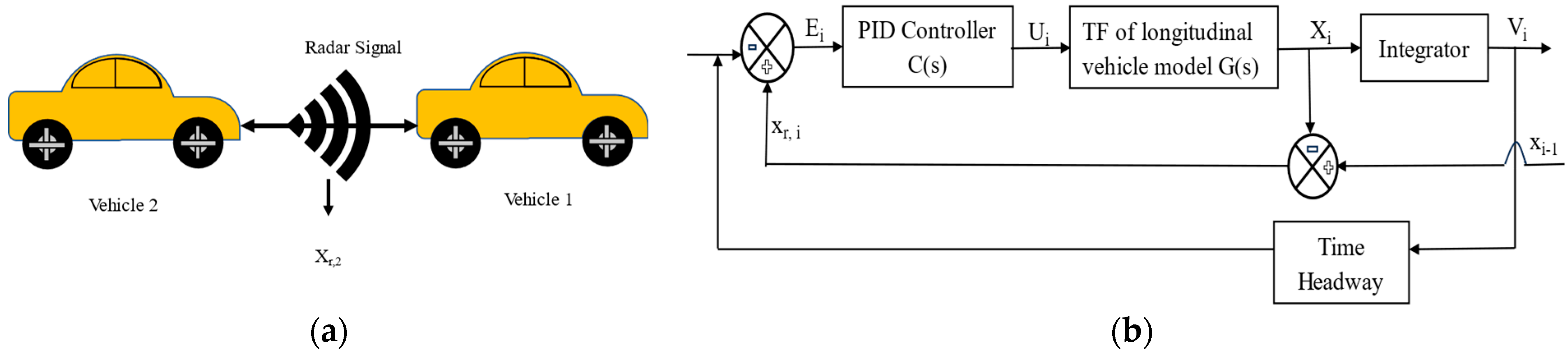
2.1. ACC Assisted Platoon

ACC plays a critical role in regulating vehicle speed and maintaining safe distances, particularly in vehicle platooning scenarios. Different issues for detection and control systems occur due to the limits of RADAR/LiDAR methods in autonomous vehicle applications. Modern signal processing techniques, including Doppler processing, range-angle mapping, and micro-Doppler signature analysis, allow for the simultaneous tracking of pedestrians and automobiles in radar-based detection systems. Even though these systems operate well in adverse weather and different lighting circumstances, their resolution capabilities are limited, particularly when it comes to accurately recognizing shapes and detecting minute objects. Additionally, radar systems may encounter difficulties differentiating between closely spaced objects due to interference from multiple reflections [43]. High-precision 3D point cloud data are made available for road geometry mapping and obstacle identification by the combination of LiDAR technology with camera-based curve estimate methods. LiDAR systems suffer from several drawbacks such as more severe performance in precipitation, high processing costs for real-time analysis, and less efficacy at greater distances. Although there are still issues with synchronizing several sensor data streams and ensuring dependable operation in all climatic situations, the combination of these technologies with camera-based systems aims to get over the constraints of individual sensors. To ensure reliable vehicle dynamics control during curve navigation, the adaptive control frameworks must further take sensor delay and measurement errors into consideration [44].
ACC systems utilize RADAR or LiDAR sensors to measure distances between vehicles and adjust speed based on predetermined spacing policies, ensuring stable platooning. For instance, the platoon-based adaptive cruise control (PACC) strategy introduces a leader-following topology to reduce traffic oscillations in CAV environments, employing both feedback and feed-forward mechanisms to enhance platoon stability and reduce traffic disturbances [45]. The enhanced ACC models, like the Intelligent Driver Model (IDM), incorporate real-time traffic dynamics and AI techniques such as reinforcement learning and long short-term memory (LSTM) networks. These models optimize vehicle behaviour by predicting traffic conditions, dynamically improving performance in dense traffic scenarios [46]. Hybrid control strategies in cooperative adaptive cruise control (CACC) systems further combine real-time sensor data with vehicle-to-vehicle communication. This dual approach ensures both safety and stability, even during communication disruptions, making it particularly useful in congested traffic or during complex maneuvers like lane changes [47]. For electric vehicles, adaptive eco-cruising control strategies are designed to optimize energy consumption by dynamically adjusting acceleration and deceleration in response to changing traffic conditions. This approach helps reduce energy consumption and lower carbon emissions, particularly in urban environments with frequent stop-and-go traffic [48]. The advanced ACC systems aimed at collision risk avoidance employ predictive modeling to adjust vehicle speeds based on the predicted positions of surrounding vehicles. These systems have been shown to reduce collisions and improve safety by predicting lane changes and maintaining safe distances between vehicles [49].
The control framework for the ACC-assisted platoon controller is depicted in Figure 1b. Within this structure, the longitudinal dynamics of the vehicle can be expressed as an open-loop transfer function denoted as G(s). The assumed longitudinal dynamics model for the i t h vehicle is as follows:
G s = k i s 2 τ i s + 1 e θ s   f o r   i 1
where s represents the Laplace operator. Additionally, τ i stands for the inverse of the open-loop bandwidth of the longitudinal dynamics, where ki represents the gain of the transfer function model, and for the ideal scenario, its value is assumed to be 1. θ represents the delay element introduced by the actuator and other internal communications within the control structure. In this context, a PID controller is used to attain the necessary and adequate control for operating the plant and obtaining the desired outputs. The transfer function of this PID controller, denoted as C(s), is defined as follows:
C s = k p + k i s + k d s   f o r   i 1
The PID controller’s gain values have been computed directly by utilizing the gain and phase values of both the open-loop and PID transfer functions, as outlined below:
O s = C s . G s   f o r   i 1
Subsequently, the closed-loop system transfer function is expressed as follows:
T i s = G i s C i s 1 + G i s C i s H i s
Here, H i s represents the transfer function for the spacing policy. The calculation of the desired distance for vehicles has been based on a spacing policy dependent on velocity. The desired spacing is defined as follows:
x d , i = x 0 + h
where
x 0 = 0.01 + 0.363 v + 0.011 v 2
x d , i = x 0 + h 1 v + h 2 v 2
where h 1 and h 2 represent constants, while x 0 signifies the minimum distance that must be upheld by the current vehicle in relation to the preceding vehicle to prevent potential collisions. This minimum distance is also described as a function of velocity.

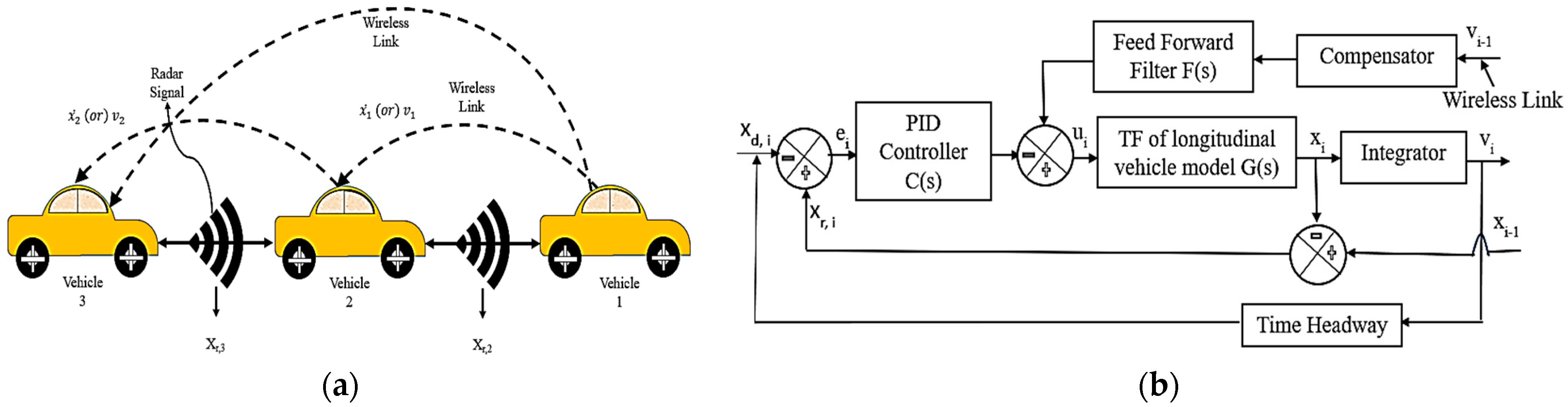
2.2. CACC Assisted PLATOON

CACC is an extension of ACC that incorporates cooperative communication between vehicles to achieve improved traffic flow and coordination. In CACC, not only does each vehicle keep a desired distance from the preceding vehicle, but it also communicates with other vehicles in the platoon. This communication enables the vehicles to synchronize their movements and act cooperatively, resulting in smoother and more efficient platoon behavior. The schematic representation of the platoon formation assisted by CACC is illustrated in Figure 2a. In CACC, vehicles exchange information about their speed, position, and acceleration with neighboring vehicles through vehicle-to-vehicle (V2V) communication, usually facilitated by a Vehicular Ad hoc Network (VANET). By receiving real-time information from other vehicles, each CACC-equipped vehicle can adjust its speed and position more proactively, reducing inter-vehicle gaps and improving traffic flow.
Within the CACC structure, two additional components have been integrated to jointly execute a feed-forward control strategy. This integration is necessary due to potential delays and noise that wireless data may encounter within the communication channel. To counter the effects of wireless delay, a compensating network has been introduced, featuring a reverse transfer function corresponding to the delay and noisy channel. The purpose of the feed-forward filter is to transform the received signal into a suitable control signal format. In this paper, the distance parameter has been chosen as both an input and output parameter for the CACC system. In Figure 2b, the current vehicle receives velocity information from the preceding vehicle through the wireless link, as previously mentioned. When the communication link fails or becomes disconnected, the CACC system transitions to an ACC mode. The signal received by the i t h vehicle, subject to a delay δ i , is expressed in terms of the Laplace operator £ ().
£ x ˙ i 1 t δ i = e δ i s . s . x i 1   f o r   i 1
In this context, the term e δ i s represents the delay introduced by the wireless link. The compensator is designed with the primary objective of mitigating this delay and other sources of noise. To design the feed-forward filter, the transformation of the error signal has been determined, and it is equated to zero to derive the feed-forward transfer function. This transformation of the error signal can be expressed as follows:
E s = 1 G s F s H s 1 + G s C s H s s   X i 1 s   f o r   i 1
Furthermore, to attain string stability and establish a cohesive vehicle platoon, it is imperative for the error signal value to converge toward zero. Consequently, the expression for the feed-forward transfer function is as follows:
F s = G s H s s 1
The condition outlined above serves as both the essential and adequate requirement aimed at the implementation of a feed-forward filter, ensuring the maintenance of string stability and the successful formation of a vehicle platoon within a CACC structure. CACC achieves these benefits by enabling vehicles to maintain precise spacing, communicate with one another, and coordinate their movements, making it a promising solution for addressing critical challenges in modern transportation.

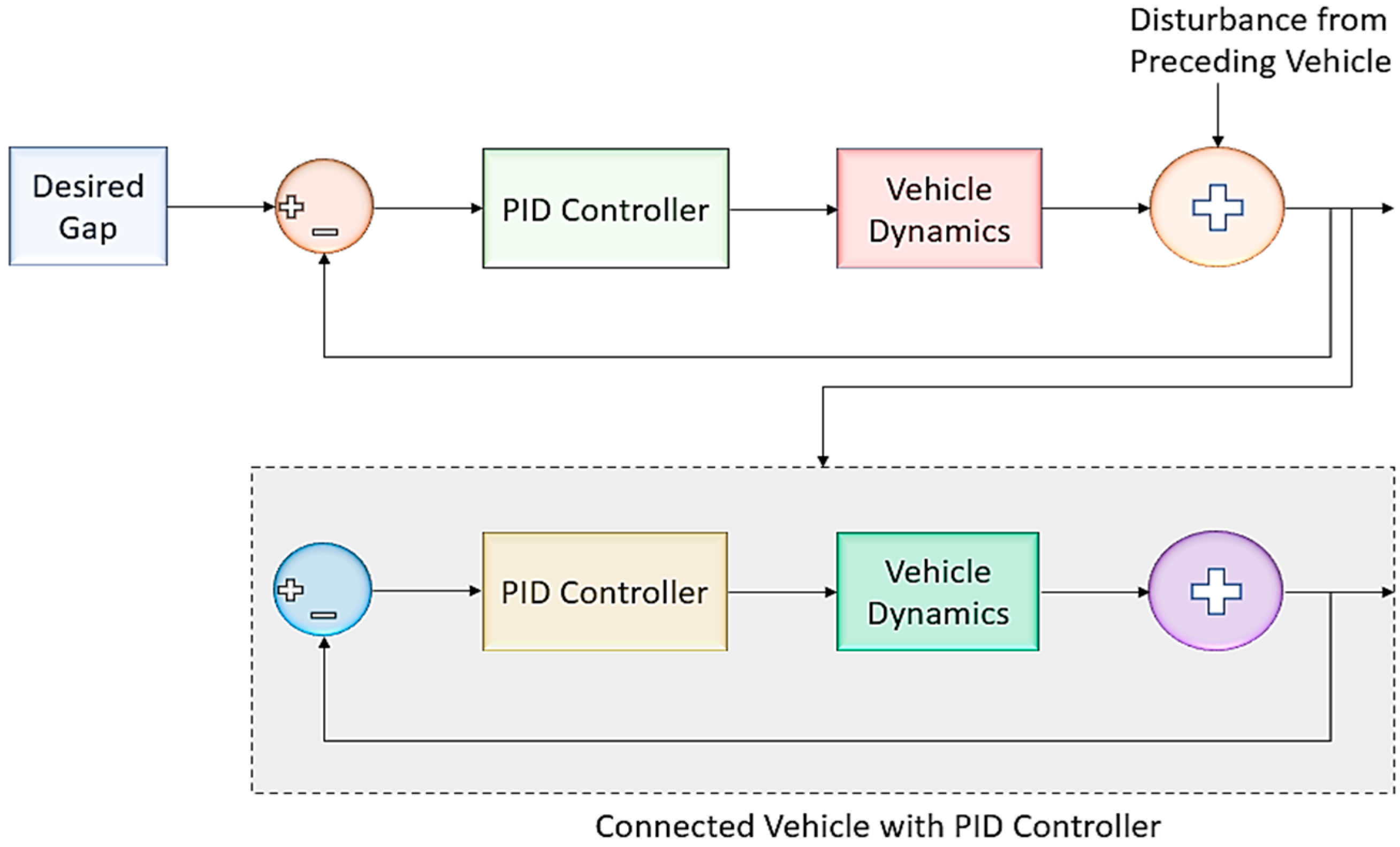
2.3. Implementation of PID Controller

PID controller along with its adaptations is extensively utilized globally to regulate the majority of feedback loops. Whether implemented as a standalone solution or as part of comprehensive control systems, the PID controller is recognized for its broad applicability across various control scenarios. In the context of vehicle platooning, each vehicle can employ PID control to regulate its speed and maintain the desired spacing from the preceding vehicle. This approach is particularly effective in situations where the precise mathematical model of the control system is unknown, making analytical control and design methods impractical.
Figure 3 represents the formation of a platoon with the PID controller. To manage the inter-vehicle distance effectively, a PID controller was implemented in a vehicle. This controller takes the current inter-vehicle gap between vehicles as input and generates a velocity reference for each follower vehicle. This velocity reference is targeted at achieving the desired inter-vehicle distance relative to the preceding vehicle. After incorporating the vehicle parameters provided in Table 1, especially its mass as per the Honda City-Petrol MT model, the vehicle’s transfer function can be expressed as follows:
G s = 1 0.3 s 3 + s 2
The standard PID controller can be expressed as
c t = K p . e t + K i . 0 t e t d t + K d . d   e t d t
where K p represents the proportional gain, K i denotes the integral gain in the control system and K d stands for the derivative gain. dt signifies the variation over time, c(t) is the control variable for the system and e(t) indicates the discrepancy relating the desired value and the definite value at a specific time, denoted as t. The PID controller gains are found for minimum overshoot, and the resulting time-domain characteristics are presented in Table 2.

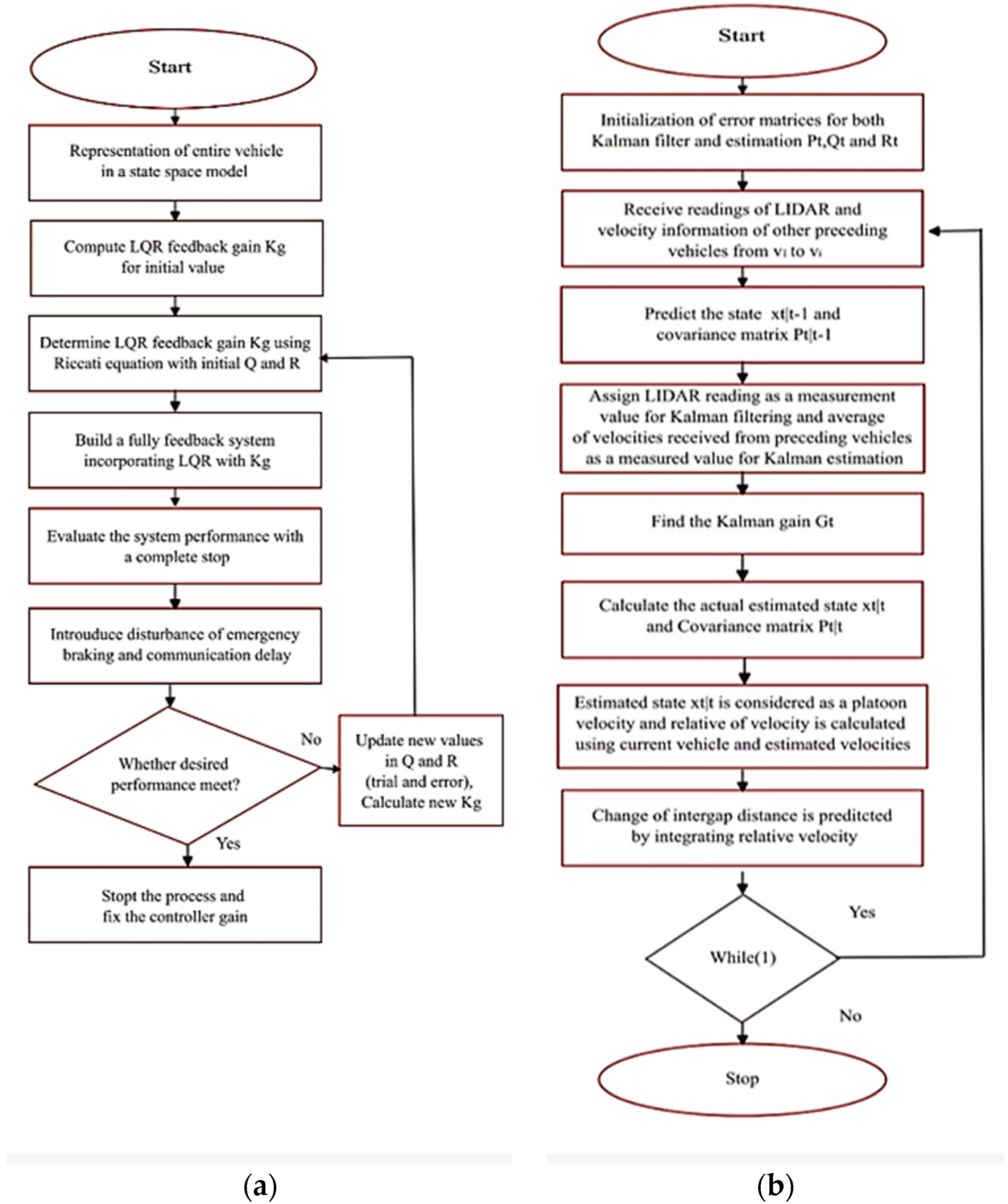
3. LQR Controller for Platoon

The development of LQR control for a coordinated platoon is shown in Figure 4. It involves creating a control strategy to regulate the behavior of autonomous vehicles within the platoon establishment. LQR is an optimal control technique that minimizes a quadratic cost function, making it valuable for controlling linear systems subject to constraints. In platoon control, LQR optimizes spacing and speed control between vehicles by first defining a state-space representation of the platoon dynamics. A cost function is designed to penalize deviations from desired states and control efforts. Utilizing this state-space representation and cost function, LQR controller gains are computed by resolving the Riccati equation, allowing for the computation of control inputs based on the platoon’s current state.
The coordinated platoon has been characterized using a state-space model, and the values of Q and R have been adjusted according to the current state and the associated feedback gain (Kg) determined through the Riccati equation. This gain can be incorporated into the system function iteratively until the desired system performance is achieved. In this study, Kg has been employed within the controller to ensure the maintenance of the anticipated inter-vehicle distance. The flowchart on executing the LQR approach is explained in Figure 5a. A conventional representation of a system in a state-space model can be defined as follows:
X ˙ = A . x + B . U Y = M . x + D . U
where A is the state transition matrix, B is the control input matrix, M is the measurement matrix, and D is the feed-forward matrix. X is the state variable matrix of the vehicle, and Y is the output of the system where x1, x2, and x3 are the acceleration, velocity, and position of the vehicle. The state-space model of the vehicle’s behavior as per specifications is derived using the following longitudinal dynamics model of the vehicle given in Table 1. shown as follows:
m d v d t = F r F d F r F g
where m is vehicle mass in kg, V is the vehicle velocity in m/s, F t is the tractive force, F d is the aerodynamic drag force, F r is the rolling resistance force, and F g is the gravitational force on slopes.
F d = 0.5   ρ   C _ d A v 2 F r = C _ r m g C o s ( α ) F g = m g S i n ( α )
where ρ is air density, C d is drag coefficient, A is the frontal area of the vehicle, C r is the rolling resistance coefficient, g is the gravitational acceleration, and α is the road slope angle. From the longitudinal dynamics derivation, a state-space model is obtained by substituting the vehicle parameters as follows:
X 1 X 2 ˙ X 3 ˙ ˙ = 3.33 0 0 1 0 0 0 1 0 x 1 x 2 x 3 + 1 0 0 U
Y = 3.33 0 0 0 3.33 0 0 0 3.33 x 1 x 2 x 3
The LQR framework involves optimizing a cost function J to attain a desired trajectory.
J = 0 x T t Q x t + u T t R u t d t
In the context of the LQR, Q and R matrices serve as the tuning parameters. For the system to exhibit stability, Q must be a positive semi-definite matrix, and R must be a positive definite matrix. The performance and cost (related to actuator energy consumption) are determined by the ratio between the Q and R matrices. The LQR technique enables the determination of the optimal control input through the following equation:
U = K g x
K g = R 1 B T P
The matrix P is the solution to the Algebraic Riccati equation, and it plays a pivotal role in ensuring system stability by positioning the system’s poles on the left side of the ‘s’ plane.
A T P + P A P B R 1 B T P + Q = 0
Since the inter-gap distance has been considered as an optimal output rather than a zero state, this problem is a controller rather than a regulator. So, the desired input state is multiplied by the factor K r
K r = M A B K g 1 B 1
LQR control outperforms PID control, particularly in more intricate systems. The LQR controller’s stability and performance are analyzed through simulations and fine-tuning is applied to achieve the desired control performance as seen in Table 3.

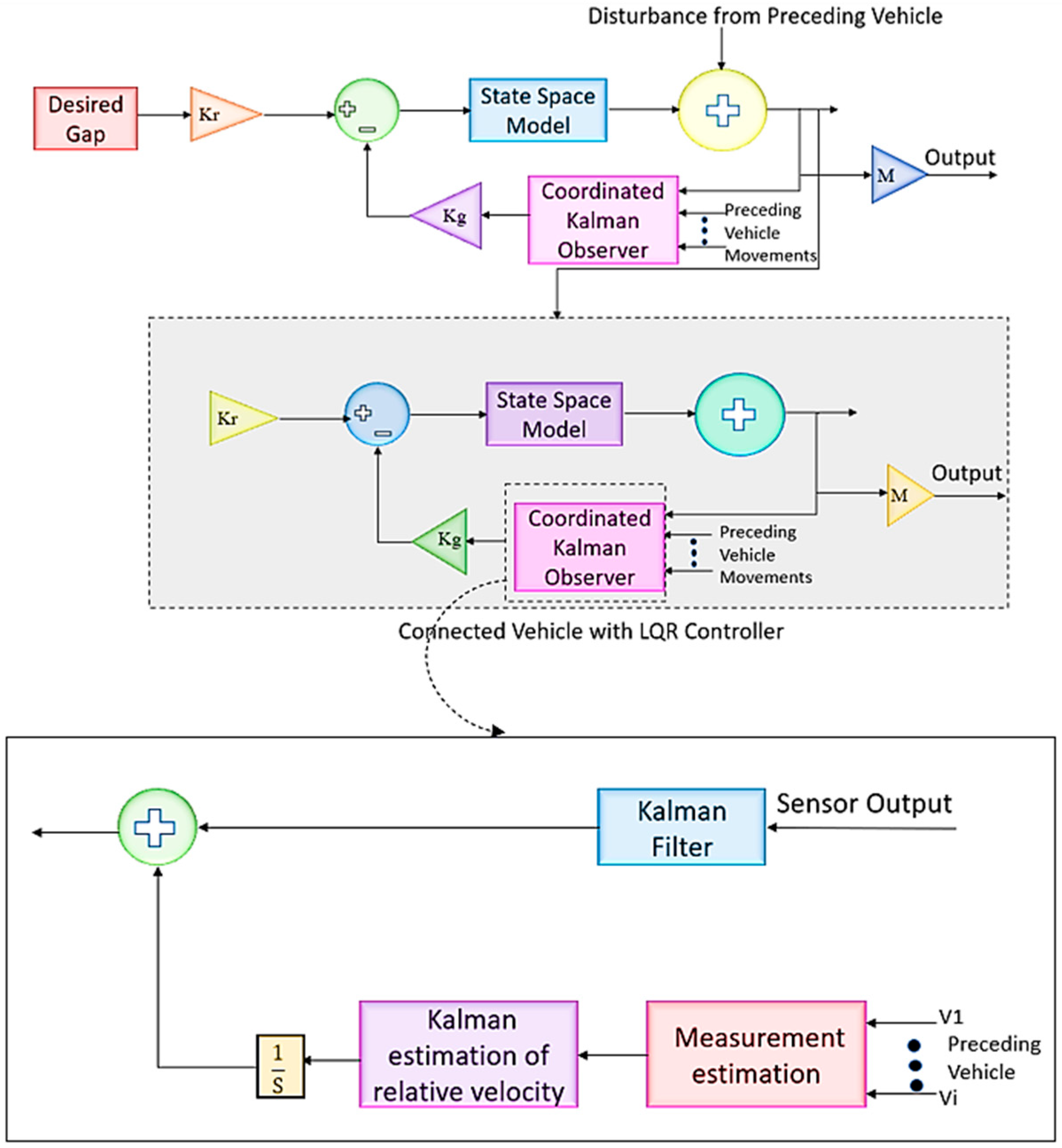
4. Coordinated Kalman Observer–LQR Controller for Platoon (CKO-LQR)

As stated in the introduction, the states of the system can be estimated mathematically using the Kalman theory. Additionally, it can be used to filter out the sounds that typically accompany sensor data. Contrary to common hardware-based filtering methods like low-pass and high-pass filters, this sort of noise filtering is software-based. The Kalman observer can be employed for both state estimation and noise reduction in sensor output. The coordinated Kalman observer is employed for assessing the velocity of preceding vehicles with the assumption of all the identical vehicles in the group. The average velocity of preceding vehicles is a measured value for estimation. Then, the relative velocity has been calculated to find the change in inter-gap prior. The following equations can be used to represent the state estimation of velocity for preceding vehicles ( x ^ t | t 1 ) and its error covariance ( P t | t 1 ) before measurement as prediction values.
  x ^ t | t 1   = A t x ^ t 1 | t 1 + B t u t   P t | t 1 = A t P t 1 | t 1 A t T + Q t  
The Kalman gain ( G t ) can be calculated as the ratio of state estimation error to the total error of state estimation and measurement error, and it is expressed as
G t = P t | t 1 M t T M t P t | t 1 M t T + R t 1
Then, the actual state estimation ( x ^ t | t ) and error covariance P t | t after the measurements are shown as follows:
x ^ t | t = x ^ t | t 1 + G t y t M t x ^ t | t 1 P t | t = 1 G t M t P t | t 1  
where Q t and R t are the state and measurement covariance errors derived from the state ( ω ) and measurement ( τ ) noises having zero mean as follows:
Q t = E ω . ω T R t = E τ . τ T
where x ^ is the estimated state; A is the state transition matrix; B is the control input matrix; u is the control input variable; P t ,   Q t , M ,   a n d   R t are the state variance, process noise variance, measurement, and measurement noise matrices; G t is Kalman gain; t | t is the current state time; t 1 | t 1 is the previous state time; and t | t 1 is the intermediate step transition time. From Figure 4., the distance of the immediate preceding vehicle can be computed using a LIDAR, and state estimation/noise cancellation for LIDAR can be performed with the following assumptions applied to Equations (24)–(26). Since there is no state transition, A t = 1, no control input, u = 0, and one state measurement M t = 1, then, Equations (27)–(29) become
x ^ t | t 1   = x ^ t 1 | t 1 P t | t 1 = P t 1 | t 1 + Q
x ^ t | t = x ^ t | t 1 + G t y t x ^ t | t 1 P t | t = 1 G t P t | t 1
G t = P t | t 1 P t | t 1 + R t 1
The initial values of the parameters are fixed as P t = 0 ,   Q t = 1 ,   a n d   R t = 10 for starting the iterations over the time period.
The overall working flow is shown in Figure 4. In CKO-LQR, there is an assumption that all the vehicles are equipped with wireless nodes, and that a vehicle is receiving speed-related information from the preceding vehicles of the platoon at regular sample intervals. These data are measurement data for Kalman estimation. Generally, these measured data are more affected by communication delays and noisy environments as a wireless medium is involved. The general procedure for forming a platoon using an LQR controller is shown in Figure 5a. Hence, the Kalman estimation of states has been applied to find the missed states and improve the accuracy of states under various error rates of sampling as explained in Figure 5b. By continuously updating the state estimate using new sensor measurements, the CKO-LQR effectively tracks the movement of the preceding vehicle in the platoon. This tracking allows the lead vehicle and other platoon members to better understand relative positions and velocities within the platoon. This improves accuracy in state estimation and predicts the inter-gap distance in advance as preceding vehicle velocities are estimated.

5. Results and Discussions

This section provides an overview of the outcomes obtained from the conducted intense simulations in MATLAB-Simulink 2023 (a), encompassing both controllers of PID and LQR with vehicle modeling. For platoon formation, a convenient group of six vehicles has been formed for experimenting with the proposed controllers and observers. The results and justifications of the proposed system have been provided in detail in the following sub-sections.

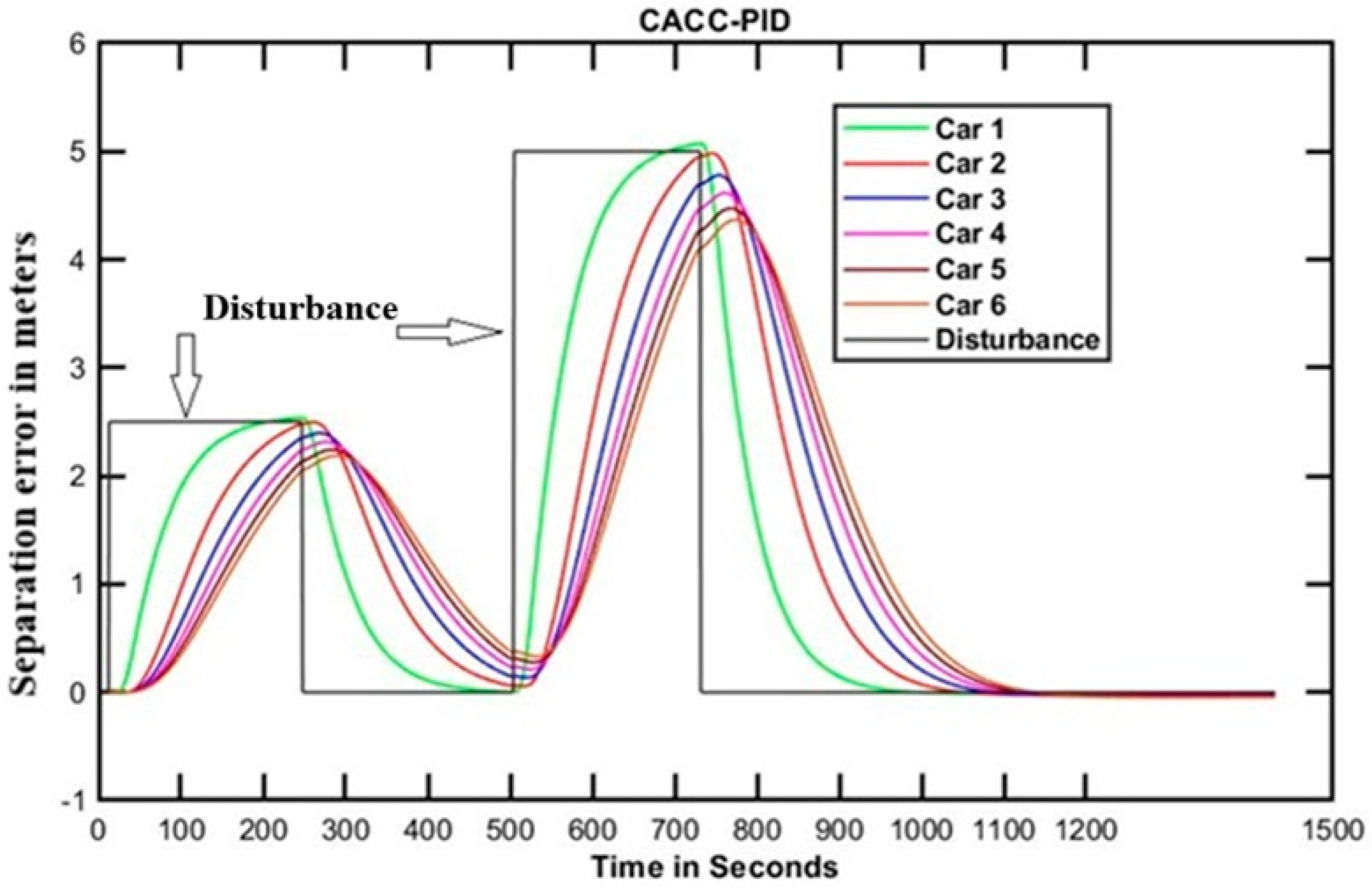
5.1. CACC Using PID Controller

The scenario of CACC with a PID controller has been implemented as discussed earlier. In this, it is undertaken that all the vehicles are identical vehicles and vehicles are considered as wireless nodes to transmit speed-related information to all the nearby vehicles with the source ID of its position in the platoon. For all the cases, a disturbance has been created on a leader vehicle when all the vehicles are at the same velocity. The resulting parameters have been measured and taken as performance parameters. The two disturbances with different amplitudes are given in the leader vehicle. Then, the separation error of successive vehicles over time is recorded. The successive vehicles are adjusting their positions for the separation error to maintain a constant inter-gap distance as shown in Figure 6. After a certain time, all the vehicles are settled down without unstable behavior. Since the performance has been affected by settling time and overshoot offered by the PID controller, the PID controller takes more time to settle down even under a more suitable PID controller design. To address these challenges and improve the system’s performance, an LQR controller is implemented. LQR controllers are known for their ability to optimize control systems even when faced with disturbances and uncertainties. By using an LQR controller, the platoon can achieve better control and responsiveness in the face of disturbance signals, ensuring smoother and more reliable operation.

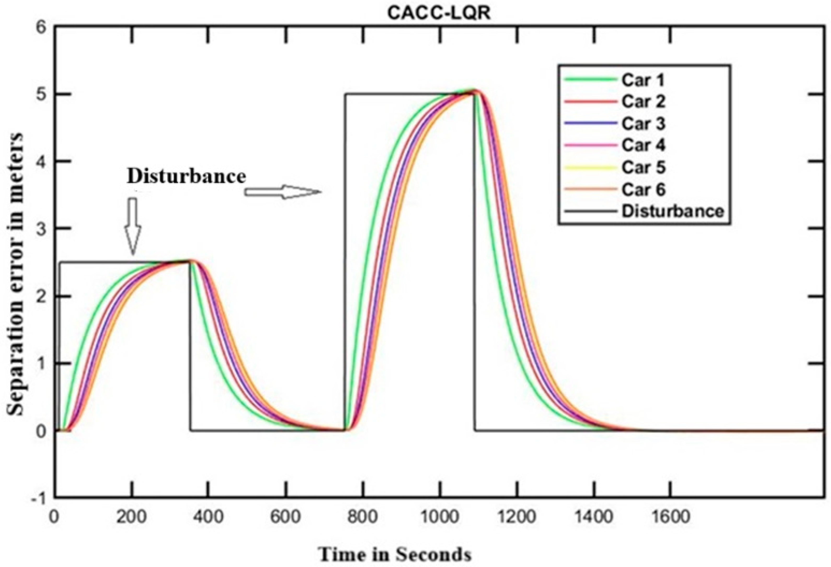
5.2. Performance of LQR Controller in a Platoon

As discussed in the previous section, the LQR is designed and implemented for the platoon. Graphs are used to visually interpret the successful performance of the LQR controller. Figure 7 illustrates how the change in inter-gap distance between vehicles in a platoon happens over time for the disturbance scenario that we applied for the LQR controller. At the outset, the time required for settling is less for the LQR controller as compared with the PID controller. In this, the inter-gap distance is assumed to be an equilibrium position of the system. The LQR regulates the equilibrium with the cost function actuator energy and error reduction. For further explanation of the results, the LQR controller is taken along with the coordinated Kalman observer as the LQR outperforms.

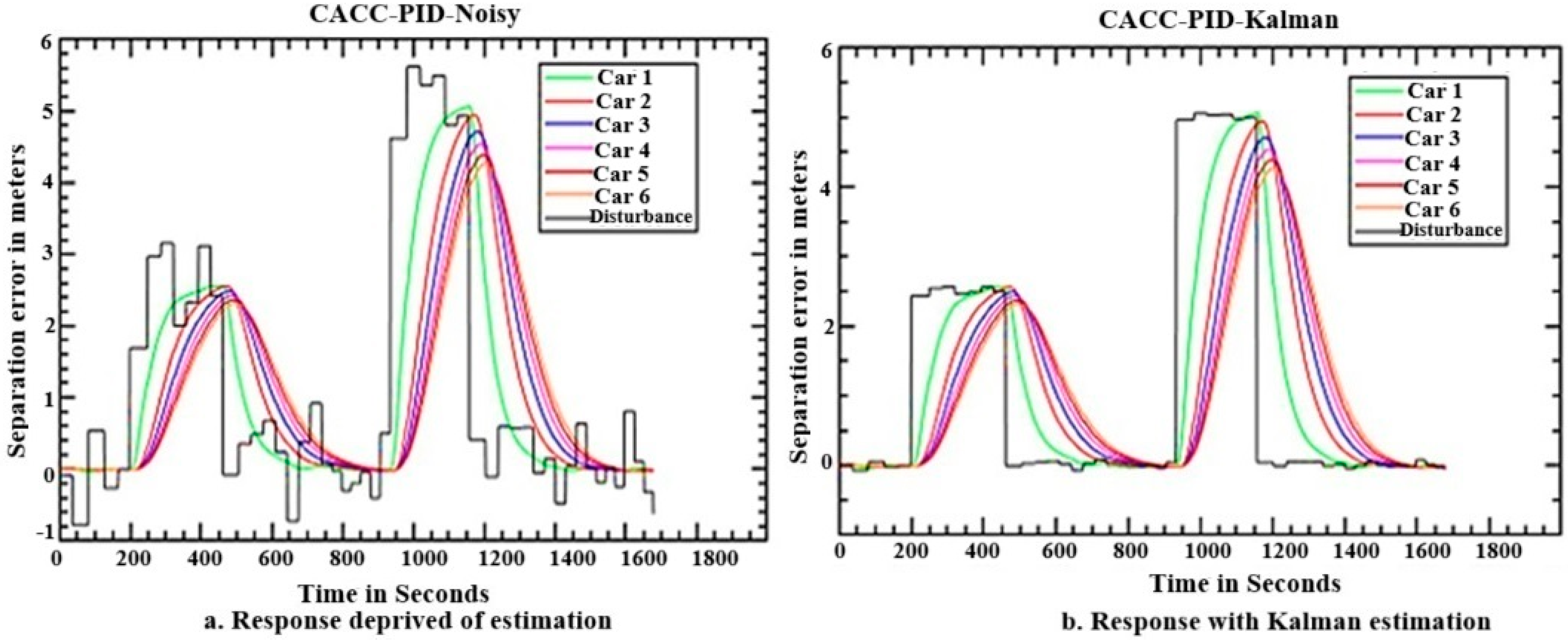
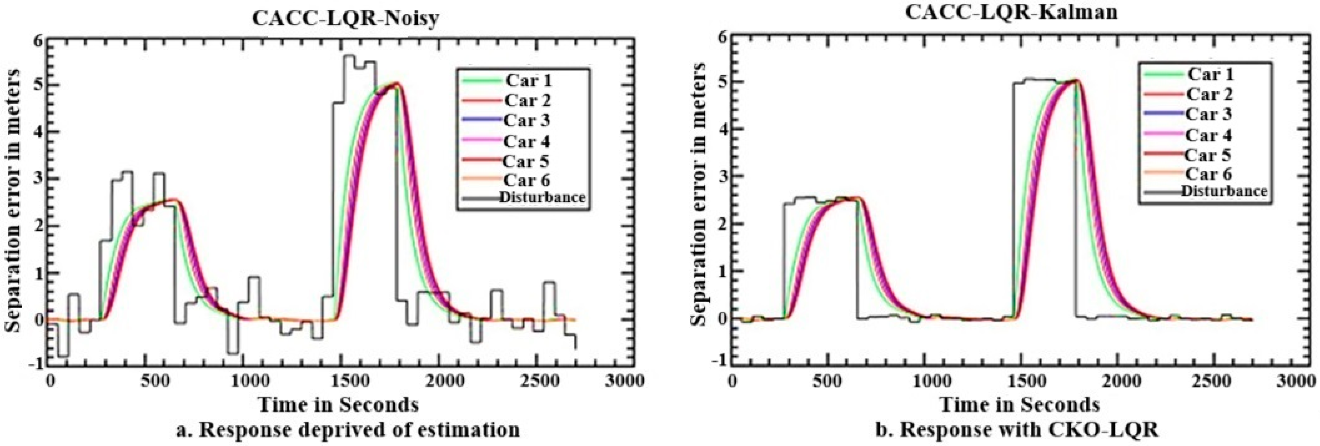
5.3. Performance of CKO-PID and CKO-LQR in a Platoon

As explained in the procedure of CKO in Figure 5b, the CKO is implemented for both PID and LQR under the assumption of measurement noise coming along with sensor data. The expected value of the noise is assumed to be zero, and it is a Gaussian distribution function. The outcomes achieved through the integration of CKO into the PID controller are illustrated in Figure 8. It explains how the noise is mitigated in Figure 8b over the noisy outputs in a normal control without estimation. In real-world scenarios, systems often experience various sources of noise, such as sensor inaccuracies, environmental disturbances, and communication delays, especially in a wireless medium.
The LQR controller is inherently well suited for optimization tasks, and when paired with a Kalman filter, it leverages accurate state estimates to make optimal control decisions. Figure 9 illustrates the results obtained by incorporating a CKO into the LQR controller. This visualization showcases the performance enhancements or changes brought about by the addition of the Kalman estimation to the control system as explained in the next section with the numerical data.

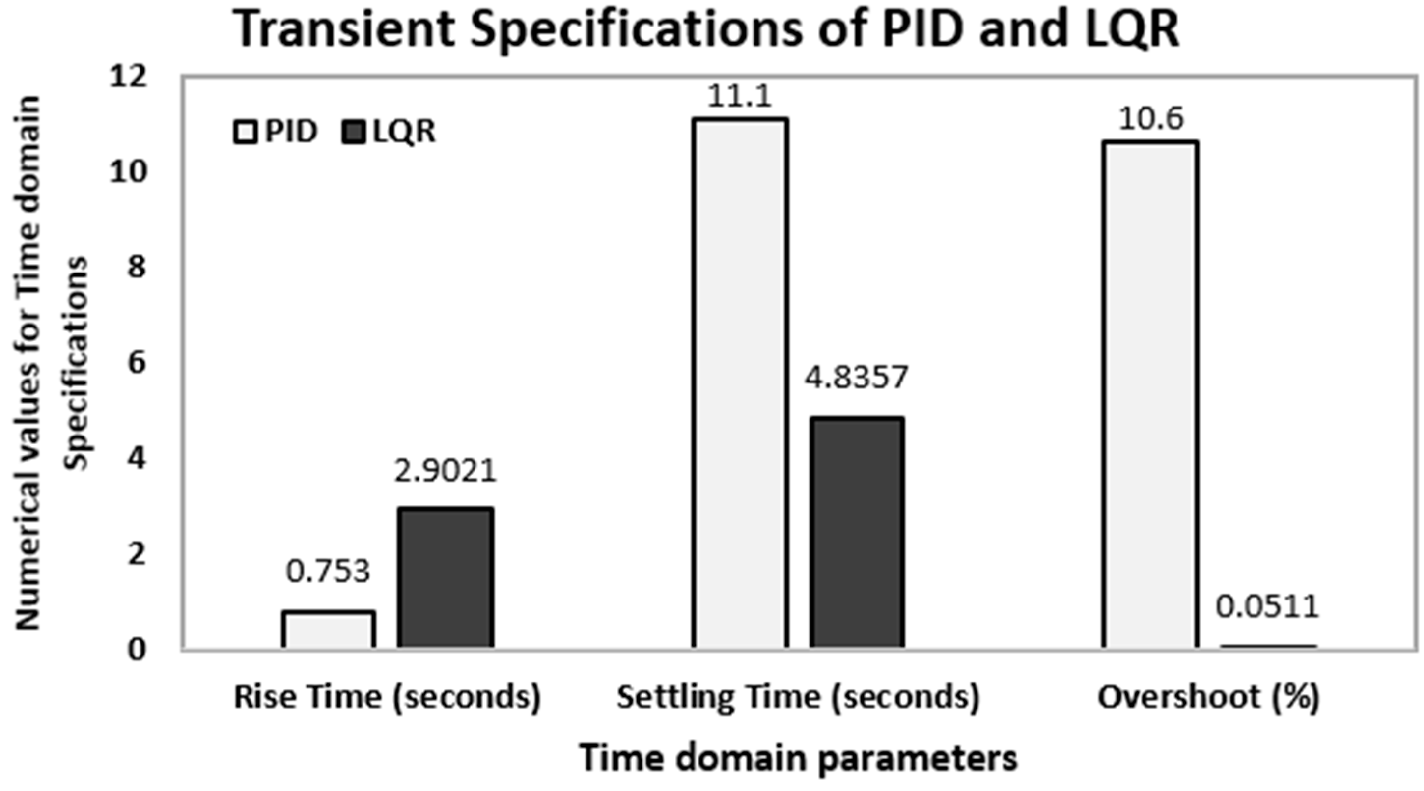
5.4. Comparison of Time-Domain Responses of PID and LQR

Figure 10 illustrates a comparison of time-domain performance metrics between a PID controller and an LQR controller. The benefits of the LQR controller over the PID controller are evident through the improved time-domain performance metrics as seen in Table 4. LQR control offers a shorter settling time and decreased overshoot percentage compared to PID control at the cost of rise time increment. LQR’s fast settling time makes it suitable for applications requiring rapid adjustments to setpoints or disturbances, while its shorter settling time and lower overshoot contribute to improved performance.

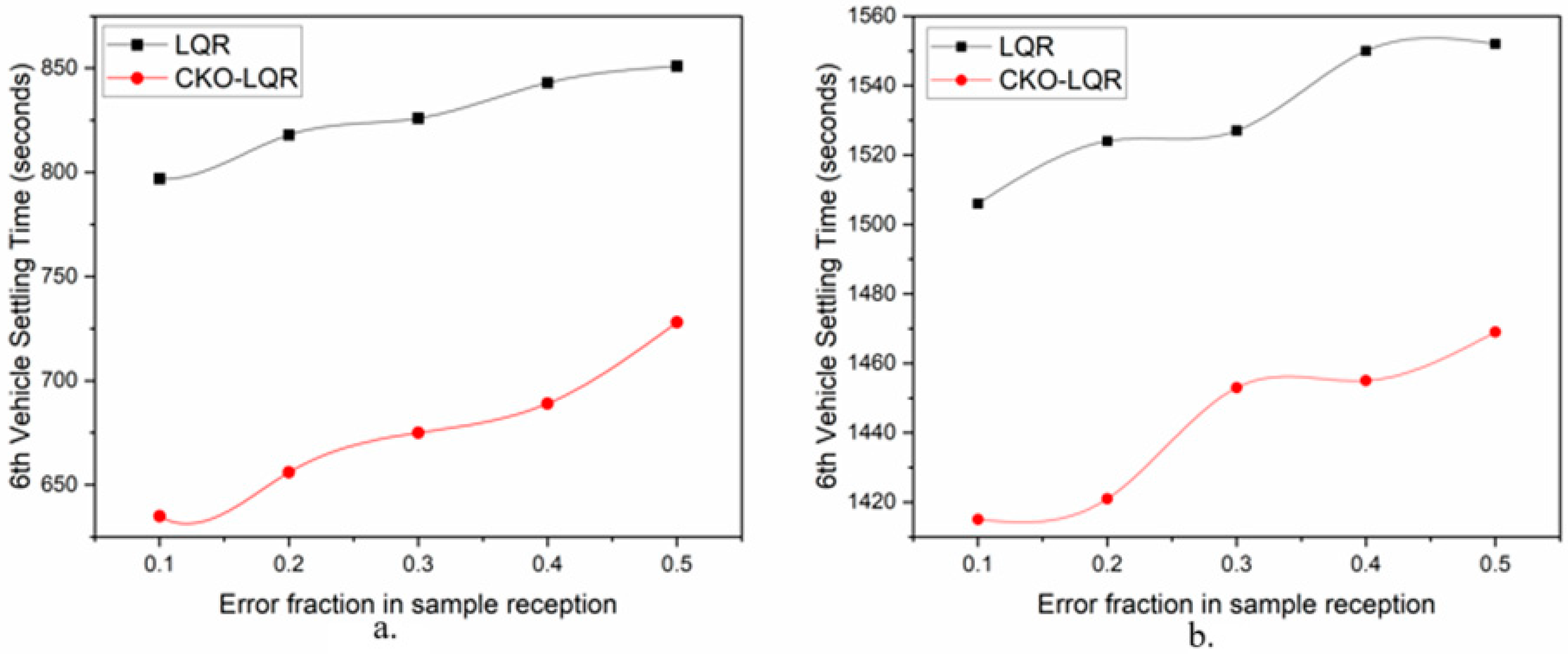
5.5. Performance of CKO-LQR in the 6th Vehicle

When subjecting the LQR controller to a disturbance, the settling time for the sixth vehicle is evaluated and contrasted with the settling time achieved using the CKO-LQR method. Particularly, CKO-LQR results in a reduction in settling time, and this reduction serves as a benchmark when comparing various scenarios errors in sample reception for cooperative estimation as given in Table 5. In cases where the received sample count is less than the total number of samples expected from preceding vehicles due to packet losses in wireless medium, it is considered to be an error and it is given as follows:
E r r o r   f r a c t i o n   E = N o .   o f   s a m p l e s   r e c e i v e d   f o r   a   v e h i c l e T o t a l   n o .   o f   s a m p l e s   s e n t   b y   a l l   p r e c e d i n g   v e h i c l e s
This discrepancy is examined across three different scenarios, ranging from high to low error rates. Especially, the CKO-LQR algorithm consistently outperforms the conventional LQR, delivering shorter settling times under two differences as illustrated in Figure 11.

6. Conclusions

Implementing PID and LQR controllers in CACC can lead to improved vehicle following and traffic coordination. The CACC with LQR is even more effective by offering faster settling under disturbances. In addition to that, CKO-LQR estimates the velocity of a platoon in a cooperative way from the preceding vehicles to alert about the changes that happen before the onboard LIDAR/RADAR sensing in the noise environment. In the future, each vehicle will be equipped with a predictive estimator to anticipate changes in the behavior of preceding vehicles. This will further reduce the settling time of string stability under disturbances. In conclusion, the following efforts and points are made:
  • The PID and LQR controllers are designed to form a platoon.
  • The experimental results show that LQR offers faster settling under disturbance over the PID controller.
  • A CKO-LQR is proposed to estimate platoon velocity in a noisy wireless medium.
  • CKO outperforms conventional controllers even in the presence of communication errors and uncertainties.

Author Contributions

N.M.: conceptualization, writing—original draft, and writing—review and editing. M.R.M.I.: writing—review and editing and supervision. All authors have read and agreed to the published version of the manuscript.

Funding

There is no need to report any funding for this project.

Data Availability Statement

The original contributions presented in the study are included in the article, further inquiries can be directed to the corresponding author.

Acknowledgments

The authors would like to thank SRM Institute of Science and Technology, Kattankulathur, India for providing the necessary facilities to complete the project.

Conflicts of Interest

The authors declare no conflicts of interest.

References

  1. Ma, F.; Wang, J.; Zhu, S.; Gelbal, S.Y.; Yang, Y.; Aksun-Guvenc, B.; Guvenc, L. Distributed Control of Cooperative Vehicular Platoon with Nonideal Communication Condition. IEEE Trans. Veh. Technol. 2020, 69, 8207–8220. [Google Scholar] [CrossRef]
  2. Ju, Z.; Zhang, H.; Tan, Y. Distributed Deception Attack Detection in Platoon-Based Connected Vehicle Systems. IEEE Trans. Veh. Technol. 2020, 69, 4609–4620. [Google Scholar] [CrossRef]
  3. Liu, D.; Baldi, S.; Hirche, S. Collision Avoidance in Longitudinal Platooning: Graceful Degradation and Adaptive Designs. IEEE Control Syst. Lett. 2023, 7, 1694–1699. [Google Scholar] [CrossRef]
  4. Hidayatullah, M.R.; Juang, J.C. Centralized and distributed control framework under homogeneous and heterogeneous platoon. IEEE Access 2021, 9, 49629–49648. [Google Scholar] [CrossRef]
  5. Flores, C.; Merdrignac, P.; De Charette, R.; Navas, F.; Milanes, V.; Nashashibi, F. A Cooperative Car-Following/Emergency Braking System with Prediction-Based Pedestrian Avoidance Capabilities. IEEE Trans. Intell. Transp. Syst. 2019, 20, 1837–1846. [Google Scholar] [CrossRef]
  6. Rosenstatter, T.; Englund, C. Modelling the Level of Trust in a Cooperative Automated Vehicle Control System. IEEE Trans. Intell. Transp. Syst. 2018, 19, 1237–1247. [Google Scholar] [CrossRef]
  7. Groelke, B.; Earnhardt, C.; Borek, J.; Vermillion, C. A Predictive Command Governor-Based Adaptive Cruise Controller With Collision Avoidance for Non-Connected Vehicle Following. IEEE Trans. Intell. Transp. Syst. 2022, 23, 12276–12286. [Google Scholar] [CrossRef]
  8. Tian, B.; Deng, X.; Xu, Z.; Zhang, Y.; Zhao, X. Modeling and Numerical Analysis on Communication Delay Boundary for CACC String Stability. IEEE Access 2019, 7, 168870–168884. [Google Scholar] [CrossRef]
  9. Nandhini, M.; Mohamed Rabik, M. A new spacing policy in a platoon using extremum-seeking controller on an anti-lock braking system. Trans. Inst. Meas. Control July 2024. [Google Scholar] [CrossRef]
  10. Wang, Z.; Gao, Y.; Fang, C.; Liu, L.; Zeng, D.; Dong, M. State-Estimation-Based Control Strategy Design for Connected Cruise Control with Delays. IEEE Syst. J. 2023, 17, 99–110. [Google Scholar] [CrossRef]
  11. Dahal, P.; Mentasti, S.; Arrigoni, S.; Braghin, F.; Matteucci, M.; Cheli, F. Extended Object Tracking in Curvilinear Road Coordinates for Autonomous Driving. IEEE Trans. Intell. Veh. 2023, 8, 1266–1278. [Google Scholar] [CrossRef]
  12. Deng, Q. A General Simulation Framework for Modeling and Analysis of Heavy-Duty Vehicle Platooning. IEEE Trans. Intell. Transp. Syst. 2016, 17, 3252–3262. [Google Scholar] [CrossRef]
  13. Hussain, R.; Zeadally, S. Autonomous cars: Research results issues and future challenges. In IEEE Communications Surveys & Tutorials; IEEE: New York, NY, USA, 2019; Volume 21, pp. 1275–1313. [Google Scholar]
  14. Zhou, Z.; Li, L.; Qu, X.; Ran, B. PACC: A platoon-based adaptive cruise control strategy based on leader-following information topology to mitigate traffic oscillations under CAV environment. Phys. A Stat. Mech. Its Appl. 2024, 654, 130117. [Google Scholar] [CrossRef]
  15. Viadero-Monasterio, F.; Meléndez-Useros, M.; Jiménez-Salas, M.; Boada, B.L. Robust adaptive heterogenous vehicle platoon control based on disturbances estimation and compensation. IEEE Access 2024, 12, 96924–96935. [Google Scholar] [CrossRef]
  16. Chaurasia, V.; Tiwari, A.N.; Tripathi, S.M. Optimal hybrid strategy in adaptive cruise control system for enhanced autonomous vehicle stability and safety. Comput. Electr. Eng. 2024, 118, 109377. [Google Scholar] [CrossRef]
  17. Liang, Y.; Dong, H.; Li, D.; Song, Z. Adaptive eco-cruising control for connected electric vehicles considering a dynamic preceding vehicle. eTransportation 2024, 19, 100299. [Google Scholar] [CrossRef]
  18. Jiang, Y.; Cong, H.; Chen, H.; Wu, Y.; Yao, Z. Adaptive cruise control design for collision risk avoidance. Phys. A Stat. Mech. Its Appl. 2024, 640, 129724. [Google Scholar] [CrossRef]
  19. Lopez, J.; Sanchez-Vilarino, P.; Sanz, R.; Paz, E. Efficient Local Navigation Approach for Autonomous Driving Vehicles. IEEE Access 2021, 9, 79776–79792. [Google Scholar] [CrossRef]
  20. Mwaffo, V.; Curry, J.S.; Iudice, F.L.; De Lellis, P. Pause-and-Go Self-Balancing Formation Control of Autonomous Vehicles Using Vision and Ultrasound Sensors. IEEE Trans. Control Syst. Technol. 2021, 29, 2299–2311. [Google Scholar] [CrossRef]
  21. Djouadi, H.; Ouari, K.; Belkhier, Y.; Lehouche, H. Real-Time HIL Simulation of Nonlinear Generalized Model Predictive-Based High-Order SMC for Permanent Magnet Synchronous Machine Drive. Int. Trans. Electr. Energy Syst. 2024, 2024, 5536555. [Google Scholar] [CrossRef]
  22. Guo, G.; Li, P.; Hao, L.Y. A New Quadratic Spacing Policy and Adaptive Fault-Tolerant Platooning with Actuator Saturation. IEEE Trans. Intell. Transp. Syst. 2022, 23, 1200–1212. [Google Scholar] [CrossRef]
  23. Lan, J.; Zhao, D.; Tian, D. Data-Driven Robust Predictive Control for Mixed Vehicle Platoons Using Noisy Measurement. IEEE Trans. Intell. Transp. Syst. 2023, 24, 6586–6596. [Google Scholar] [CrossRef]
  24. Dutta, R.G.; Hu, Y.; Yu, F.; Zhang, T.; Jin, Y. Design and Analysis of Secure Distributed Estimator for Vehicular Platooning in Adversarial Environment. IEEE Trans. Intell. Transp. Syst. 2022, 23, 3418–3429. [Google Scholar] [CrossRef]
  25. Devika, K.B.; Rohith, G.; Yellapantula VR, S.; Subramanian, S.C. A Dynamics-Based Adaptive String Stable Controller for Connected Heavy Road Vehicle Platoon Safety. IEEE Access 2020, 8, 209886–209903. [Google Scholar] [CrossRef]
  26. Guo, G.; Li, P.; Hao, L.Y. Adaptive Fault-Tolerant Control of Platoons with Guaranteed Traffic Flow Stability. IEEE Trans. Veh. Technol. 2020, 69, 6916–6927. [Google Scholar] [CrossRef]
  27. Dey, K.C.; Yan, L.; Wang, X.; Wang, Y.; Shen, H.; Chowdhury, M.; Yu, L.; Qiu, C.; Soundararaj, V. A Review of Communication, Driver Characteristics, and Controls Aspects of Cooperative Adaptive Cruise Control (CACC). IEEE Trans. Intell. Transp. Syst. 2016, 17, 491–509. [Google Scholar] [CrossRef]
  28. Wang, Z.; Sun, K.; Ma, S.; Sun, L.; Gao, W.; Dong, Z. Improved Linear Quadratic Regulator Lateral Path Tracking Approach Based on a Real-Time Updated Algorithm with Fuzzy Control and Cosine Similarity for Autonomous Vehicles. Electronics 2022, 11, 3703. [Google Scholar] [CrossRef]
  29. Coppola, A.; Lui, D.G.; Petrillo, A.; Santini, S. Eco-Driving Control Architecture for Platoons of Uncertain Heterogeneous Nonlinear Connected Autonomous Electric Vehicles. IEEE Trans. Intell. Transp. Syst. 2022, 23, 24220–24234. [Google Scholar] [CrossRef]
  30. Zhang, H.; Li, L.; Xu, J.; Fu, M. Linear quadratic regulation and stabilization of discrete-time systems with delay and multiplicative noise. IEEE Trans. Autom. Control 2015, 60, 2599–2613. [Google Scholar] [CrossRef]
  31. Harfouch, Y.A.; Yuan, S.; Baldi, S. An adaptive switched control approach to heterogeneous platooning with intervehicle communication losses. IEEE Trans. Control Netw. Syst. 2018, 5, 1434–1444. [Google Scholar] [CrossRef]
  32. Stankovic, S.S.; Stanojevic, M.J.; Siljak, D.D. Decentralized overlapping control of a platoon of vehicles. IEEE Trans. Control. Syst. Technol. 2000, 8, 816–832. [Google Scholar] [CrossRef]
  33. Feng, S.; Zhang, Y.; Li, S.E.; Cao, Z.; Liu, H.X.; Li, L. String stability for vehicular platoon control: Definitions and analysis methods. Annu. Rev. Control 2019, 47, 81–97. [Google Scholar] [CrossRef]
  34. Zhang, Y.; Chen, B.; Yu, L.; Ho, D.W.C. Distributed Kalman Filtering for Interconnected Dynamic Systems. IEEE Trans. Cybern. 2022, 52, 11571–11580. [Google Scholar] [CrossRef]
  35. Sun, C.; Vianney, J.M.U.; Li, Y.; Chen, L.; Li, L.; Wang, F.-Y.; Khajepour, A.; Cao, D. Proximity based automatic data annotation for autonomous driving. IEEE/CAA J. Autom. Sin. 2020, 7, 395–404. [Google Scholar] [CrossRef]
  36. Da Silva, G.R.G.; Bazanella, A.S.; Lorenzini, C.; Campestrini, L. Data-Driven LQR Control Design. IEEE Control Syst. Lett. 2019, 3, 180–185. [Google Scholar] [CrossRef]
  37. Kanieski, J.M.; Tambara, R.V.; Pinheiro, H.; Cardoso, R.; Grundling, H.A. Robust Adaptive Controller Combined With a Linear Quadratic Regulator Based on Kalman Filtering. IEEE Trans. Autom. Control 2016, 61, 1373–1378. [Google Scholar] [CrossRef]
  38. Li, X.; Guvenc, L.; Aksun-Guvenc, B. Vehicle State Estimation and Prediction for Autonomous Driving in a Round Intersection. Vehicles 2023, 5, 1328–1352. [Google Scholar] [CrossRef]
  39. Ghahestani, M.; Vali, A.; Siahi, M.; Moarefianpour, A. Stabilization of an Uncertain Maglev Train System Using Finite Time Adaptive Back-stepping Controller. Int. J. Control Autom. Syst. 2024, 22, 744–752. [Google Scholar] [CrossRef]
  40. Wei, C. Modeling and Simulation of Active Half-vehicle Suspension Based on a New Output-feedback H∞ Controller. Int. J. Control Autom. Syst. 2024, 22, 775–784. [Google Scholar] [CrossRef]
  41. Zhao, C.; Cai, L.; Cheng, P. Stability Analysis of Vehicle Platooning with Limited Communication Range and Random Packet Losses. IEEE Internet Things J. 2021, 8, 262–277. [Google Scholar] [CrossRef]
  42. Prakash, N.P.S.; Horowitz, R. Data-Driven Robust Feedback Control Design for Multi-Actuator Hard Disk Drives. IFAC-PapersOnLine 2022, 55, 131–138. [Google Scholar] [CrossRef]
  43. Viadero-Monasterio, F.; Alonso-Rentería, L.; Pérez-Oria, J.; Viadero-Rueda, F. Radar-Based Pedestrian and Vehicle Detection and Identification for Driving Assistance. Vehicles 2024, 6, 1185–1199. [Google Scholar] [CrossRef]
  44. Wang, B.; Liao, Z.; Guo, S. Adaptive Curve Passing Control in Autonomous Vehicles with Integrated Dynamics and Camera-Based Radius Estimation. Vehicles 2024, 6, 1648–1660. [Google Scholar] [CrossRef]
  45. Jee, G.; Yalagach, A.; Brinda, V.; Lalithambika, V.; Dhekane, M.V. Controller Design for Lateral Dynamics of Reusable Launch Vehicle by H-infinity Mixed Sensitivity approach. IFAC Proc. Vol. 2014, 47, 171–175. [Google Scholar] [CrossRef]
  46. Kassarian, E.; Sanfedino, F.; Alazard, D.; Montel, J.; Chevrier, C.A. Robust integrated control/structure co-design for stratospheric balloons. IFAC-PapersOnLine 2022, 55, 13–18. [Google Scholar] [CrossRef]
  47. Monnet, D.; Ninin, J.; Clement, B. Robust structured H2 synthesis for linear systems subject to time-invariant uncertainties with global optimization. IFAC-PapersOnLine 2021, 54, 341–347. [Google Scholar] [CrossRef]
  48. Lian, J.; Dimirovski, G.M.; Zhao, J. Switched Uncertain Linear Systems Control by Robust H∞ Smc Synthesis1. IFAC Proc. Vol. 2007, 40, 78–83. [Google Scholar] [CrossRef]
  49. Furenes, B.; Lie, B. Robust Control of a Solidification Process with Parametric Uncertainty. IFAC Proc. Vol. 2007, 40, 225–230. [Google Scholar] [CrossRef]
Figure 1. (a) Schematic structure of ACC assisting platoon. (b) Control structure of an ACC with time headway spacing policy.
Wevj 16 00028 g001
Figure 2. (a) Schematic representation of CACC assisting platoon. (b) Control structure of a CACC with time headway spacing policy.
Wevj 16 00028 g002
Figure 3. Platoon formation implemented with PID controller.
Wevj 16 00028 g003
Figure 4. Coordinated Kalman observer for LQR controller.
Wevj 16 00028 g004
Figure 5. (a) Platoon formation implemented with LQR controller. (b) Procedure for coordinated Kalman observer.
Wevj 16 00028 g005
Figure 6. Visual depiction of a PID controller in a platoon.
Wevj 16 00028 g006
Figure 7. Visual depiction of an LQR controller in a platoon.
Wevj 16 00028 g007
Figure 8. Implementation of Kalman filter with PID controller. (a) Response deprived of estimation. (b) Response with Kalman estimation.
Wevj 16 00028 g008
Figure 9. Implementation of Kalman filter with LQR controller. (a) Response deprived of estimation. (b) Response with CKO-LQR.
Wevj 16 00028 g009
Figure 10. Evaluating time-domain performance of PID and LQR controller.
Wevj 16 00028 g010
Figure 11. Comparison of LQR and CKO-LQR performance in the 6th vehicle (a) during 1st disturbance (b) during 2nd disturbance.
Wevj 16 00028 g011
Table 1. Vehicle parameters.
ParametersValues
Mass of the vehicle (in kg)1049
Radius of the wheel (in m)0.33
Moment of Inertia (I)0.5 × (1049) × (0.332)
Acc. due to gravity (g in ms−2)9.81
Velocity (V0 in ms−1)13.889/20.833/27.778
Table 2. Time-domain specification for PID.
SpecificationsValues
P0.1342
I0.0015782
D1.9203
N195.428
Rise Time0.753 s
Settling Time11.1 s
Overshoot10.6%
Peak1.11
Gain Margin40.1 dB @ 25.2 rad/s
Phase Margin60 deg @ 1.71 rad/s
Table 3. Time-domain specifications for LQR.
SpecificationsValues
Q100*eye (3)
R0.5
Rise Time2.9021 s
Settling Time4.8357 s
Settling Min45.0828 s
Settling Max50.0255 s
Overshoot0.0511
Undershoot0
Table 4. Comparison of time-domain response of PID and LQR.
Transient SpecificationsPIDLQR
Rise Time0.753 s2.9021 s
Settling Time11.1 s4.8357 s
Overshoot10.6%0.0511%
Table 5. Settling time for 6th vehicle.
Error FractionTime Taken to Settling Down by nth Vehicle, Here 6th Vehicle (Seconds)
LQRCKO-LQR
Disturbance IDisturbance IIDisturbance IDisturbance
II
0.585115527281469
0.484315506891455
0.382615276751453
0.281815246561421
0.179715066351415
Disclaimer/Publisher’s Note: The statements, opinions and data contained in all publications are solely those of the individual author(s) and contributor(s) and not of MDPI and/or the editor(s). MDPI and/or the editor(s) disclaim responsibility for any injury to people or property resulting from any ideas, methods, instructions or products referred to in the content.

