Article

Analysis of Leakage Current in Dynamic Wireless Power Transfer Systems Based on LCC-S Architecture

1
Energy Research Institute of Shandong Academy of Sciences, School of Energy and Power Engineering, Qilu University of Technology (Shandong Academy of Sciences), Jinan 250014, China
2
School of Electrical Engineering, Shandong University, Jinan 250014, China
*
Author to whom correspondence should be addressed.
These authors contributed equally to this work.
World Electr. Veh. J. 2024, 15(6), 225; https://doi.org/10.3390/wevj15060225
Submission received: 14 April 2024 / Revised: 16 May 2024 / Accepted: 20 May 2024 / Published: 22 May 2024

Abstract

:
This paper investigates the issue of leakage current at the transmitter in the Dynamic Wireless Power Transfer (DWPT) system for electric vehicles and puts forward a novel bilateral resonant compensation topology structure based on the conventional LCC-S architecture. Based on the LCC-S framework, a circuit model was developed for traditional (unilateral)/bilateral resonant compensation topologies. The Fourier series voltage-to-earth expansions for the power supply rail were deduced for both topologies. Subsequently, the voltage-to-earth waveforms for the power supply rail were obtained by utilizing the Fourier series expansions of the voltage-to-earth and the corresponding circuit simulation models. The results demonstrate the efficacy of the bilateral resonant compensation topology in mitigating higher-order harmonics of the voltage to earth on the power supply rail by effectively suppressing the distortion in the leakage current and minimizing its conduction. The effectiveness of the double-ended resonant compensation topology in suppressing leakage current conduction has been verified through experimental tests and waveform comparisons of the voltage to earth and leakage current on the power supply rail under two different topologies. Through experimental testing, during which the unilateral/bilateral resonant compensation topologies were compared, an analysis was conducted on the waveforms of the voltage to earth and leakage current of the power supply rail. The results verified the effectiveness of the bilateral resonant compensation topology in mitigating the conduction of leakage current. This study provides empirical evidence supporting the use of the bilateral resonant compensation topology for suppressing leakage current in power rail applications.

1. Introduction

Since the discovery of induction coils in the late 19th century, wireless power transfer (WPT) technology has been in existence and has been evolving for over 120 years. Especially in the 21st century, WPT technology has found increasingly widespread applications [1,2,3].
The rapid advancement of electric vehicles has necessitated the exploration of alternative charging methods that surpass the limitations of traditional wired methods in terms of automation and convenience. In response to this demand, wireless charging technology has emerged as a viable solution, offering notable advantages such as enhanced safety, convenience, and flexibility. As a result, wireless charging has found extensive application in the electric vehicle industry, revolutionizing the way vehicles are charged and paving the way for a more seamless and efficient charging experience.
Static wireless power transfer technology (SWPT) for electric vehicles has matured gradually. However, this technology cannot fulfill the needs of electric vehicles for long-distance travel, and it has drawbacks such as short battery life and poor convenience. Therefore, dynamic wireless power transfer technology (DWPT), which allows charging while driving, has started to receive attention. New resonance topologies and control strategies have emerged continuously [4,5,6].
Wireless charging technology for electric vehicles commonly adopts magnetic resonance coupling technology, which ensures efficient and stable power transmission during the dynamic charging process of electric vehicles [7,8]. Dynamic charging refers to charging while the vehicle is traveling. The energy transmission coil structure of the dynamic wireless energy transmission system for electric vehicles mainly includes the centralized power supply rail mode [9] and the segmented power supply rail mode [10], in which the receiving end is a receiving coil mounted on the bottom of the vehicle, and the transmitting end is usually a long, straight power supply rail fixed to the ground [11]. However, in practical applications, it has been observed that when the long, straight power supply rail is energized, an electric field is formed between the power supply rail and the ground, causing the power supply rail to discharge to the ground through the atmosphere [12]. The leakage current generated by this discharge flows through a low-impedance path in the transmitter circuit. Leakage current can interfere with signal communication between devices and result in significant electromagnetic interference issues.
Currently, researchers are primarily focusing on the electromagnetic interference (EMI) issues caused by parasitic capacitance in the SWPT systems of electric vehicles. Reference [13] shows the stray capacitance between the transmitting coil and the receiving coil and establishes a circuit model based on SS-type and bilateral LCC-type WPT. It was discovered that the LCC compensation topology can effectively reduce the electromagnetic interference (EMI) caused by stray capacitance [14]. References [15,16] show that the stray capacitance between the coupling coil and the metal shielding layer in the WPT system of electric vehicles can also lead to significant EMI. Furthermore, researchers have found that noise currents in SWPT systems can be effectively reduced by optimizing the coupling coil structure [17], improving the design of the metal shielding layer [18], and introducing EMI filters and high-frequency isolation transformers.
At present, scholars have proposed methods to reduce the leakage current by adding common mode filters, optimizing the control strategy, and improving the topology [19]. Among them, the addition of common-mode filters for suppression is an effective method, but most of the research does not carry out systematic research on the EMI generation mechanism and anti-interference capability of static WPT systems and long-rail dynamic WPT systems, and there has not been a systematic study on the issues of leakage current interference in the power supply rail of DWPT systems and methods to optimize compensation topology for suppressing leakage current. The leakage current phenomenon is even more serious than the static system due to the larger capacitance to ground of the long-rail dynamic WPT system than the static system. Therefore, the research content of this topic is of great significance for the study of improving the anti-jamming capability of long-rail dynamic WPT system.
In this paper, based on the LCC-S architecture of DWPT systems, a bilateral resonant compensation topology structure is proposed. Equivalent circuit models for the unilateral resonant compensation topology structure and the bilateral resonant compensation topology structure are established. The Fourier series expansion formulas for the voltage to earth at both ends of the power supply rail at the transmitter are derived for the two topology structures. The differences in the voltage-to-earth waveform of the power supply rail under the two resonant compensation topology structures are compared through formula calculations and circuit simulations. Finally, the effectiveness of the bilateral compensation topology structure in suppressing the conduction of leakage current at the transmitter is experimentally verified.

2. Theoretical Analysis of DWPT System Based on LCC-S Structure

Based on the LCC-S resonant compensation topology, the structure of the electric vehicle DWPT system is shown in Figure 1. L f represents the series compensating inductance at the transmitter end, while C f represents the parallel compensating capacitance. L s indicates the inductance of the receiving coil, and C s represents the series compensating capacitance at the receiver end. M represents the mutual inductance between the power supply rail and the receiving coil. C p 1 , C p 2 , … C p ( y 1 ) , C p ( y ) denote the series compensating capacitance at the transmitter end. In the centralized power−supply rail mode, the series compensating capacitance at the transmitter end adopts a distributed compensation structure, effectively preventing a steep increase in voltage at both ends of the power supply rail due to long-distance laying.
The resonant compensation topology at the transmitter end, as shown in Figure 2, can be equivalently represented by the circuit model illustrated in Figure 1. L p 1 , L p 2 , … L p ( x 1 ) , L p ( x ) is each segment of the power supply rail, while L p 1 , L p 2 , … L p ( x 1 ) , L p ( x ) and C p 1 , C p 2 , … C p ( y 1 ) , C p ( y ) can be combined and represented as a total inductance Lp for ease of analysis and calculation. Accordingly, the transmitter end of the LCC-S topology is depicted in Figure 3, in which U in represents the inverter output voltage, I in represents the inverter output current, and I p represents the power supply rail current.
By disregarding the parasitic resistances of compensating inductance and transmitter coil inductance and considering the existence of higher-order impedances in the system, the high-order impedance at the transmitter end is exclusively odd-order owing to the frequency response characteristics and non-linear properties of inductance, capacitance, and resistance elements. The high-order impedance of the system is denoted as Z ( 2 n 1 ) , where “2n − 1” represents the odd-order impedance, with “n” being a positive integer. Then, the expressions Z ( 2 n 1 ) and Iin are as follows:
Z ( 2 n 1 ) = j ( 2 n 1 ) ω L f + j ω ( 2 n 1 ) L p × 1 j ω ( 2 n 1 ) C f j ω ( 2 n 1 ) L p + 1 j ω ( 2 n 1 ) C f
I in = U in Z ( 2 n 1 )

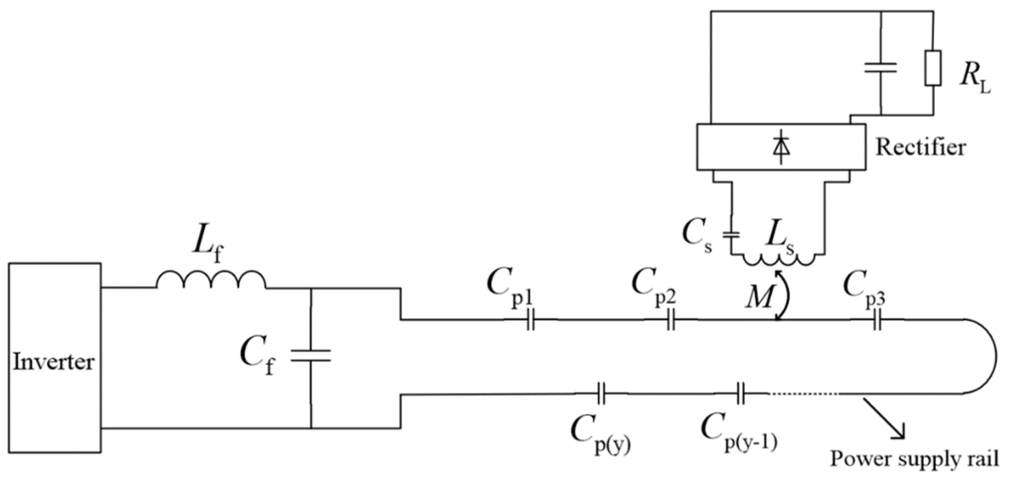
2.1. Unilateral Resonant Compensation Topology

It is widely acknowledged that when wires or cables are buried underground or in close proximity to the ground, the charge distribution of these conductors near the ground induces an electric field, leading to the generation of capacitive currents. The power supply rail at the transmitter end of the DWPT system, being essentially one or more long, straight wires, inevitably exhibits a capacitive coupling with the earth, resulting in a capacitance to ground [20]. Moreover, for the power supply rail to effectively couple with the magnetic field at the receiver end and achieve wireless power transfer, it must carry high-frequency AC current exclusively. Therefore, a high-frequency voltage difference, referred to as the voltage to earth, constantly exists between the power supply rail and the ground during its operation. This voltage to earth serves as the primary cause of leakage current generation.
In the practical application of the DWPT system, when the length of the power rail at the transmitting end remains constant and the vertical distance between the rail and the ground remains constant, the capacitance between the power rail and the ground can be considered constant. According to the formula “i = Cdu/dt”, the voltage of the power rail with respect to the ground is another key factor affecting the magnitude of leakage current. As shown in Figure 4, by neglecting the parasitic capacitance between the transmitter’s switch power supply and the heat sink, the ground capacitance between the power supply rail and the earth, denoted by C e 1 and C e 2 , emerges as the primary factor contributing to the generation of capacitive currents at the transmitter end. Here, U D represents the DC bus voltage, and A and B represent the two endpoints of the power supply rail, while point C denotes the negative terminal of the inverter’s DC bus. Although a certain amount of noise current is generated by the negative pole of the inverter circuit with respect to ground, it can be reasonably assumed that point C is at the same potential as PE concerning high-frequency voltage coupling, given that point C is adequately grounded through the Y capacitor [21]. Consequently, the voltage to earth of the power supply rail can be regarded as the voltage between points A and B relative to point C.
In accordance with the operational principle of the full-bridge inverter circuit, the Fourier series expansion of can be expressed as follows:
U in = 1 2 n 1 4 U D ( 2 n 1 ) π sin [ ( 2 n 1 ) ω π ]
Based on Figure 4, the duration of one working period for the inverter circuit is designated as T. Switches S1 and S4 are opened in the interval of 0 to T/2 and closed in the interval of T/2 to T, while switches S2 and S3 operate in the opposite manner. The voltage between points B and C, denoted as U BC , represents the voltage across switch S4. When switch S4 is closed in the inverter circuit, the voltage between points B and C is zero. When switch S4 is open, the voltage between points B and C becomes U D .
Hence, the Fourier series expansion of U BC can be expressed as follows:
U BC = U D 2 + 1 2 n 1 2 U D ( 2 n 1 ) π sin [ ( 2 n 1 ) ω π + T 2 ]
The Fourier series expansion of US2 can be represented as follows:
U S 2 = U D 2 + 1 2 n 1 2 U D ( 2 n 1 ) π sin [ ( 2 n 1 ) ω π ]
The Fourier series expansion of ULf can be represented as follows:
U L f = j ( 2 n 1 ) ω L f 1 1 2 n 1 4 U D ( 2 n 1 ) π sin [ ( 2 n 1 ) ω π ] Z 2 n 1
Simplify Equation (7) to:
U L f = 1 ( 2 n 1 ) 2 C f 1 L P L P L f 1 + 1 ω 2 ( 2 n 1 ) 2 C f 1 L P 1 2 n 1 4 U D ( 2 n 1 ) π sin [ ( 2 n 1 ) ω π ]
Let 1 ( 2 n 1 ) 2 C f 1 L P L P L f 1 + 1 ω 2 ( 2 n 1 ) 2 C f 1 L P = a , then the Fourier series expansion of U AC can be represented as follows:
U AC = U D 2 + [ 1 2 a ] 1 2 n 1 2 U D ( 2 n 1 ) π sin [ ( 2 n 1 ) ω π ]
In DWPT systems, because Lf = Lp and LfCf = 1/ω2, the expression “a” can be reduced to:
a = 1 1 ( 2 n 1 ) 2 2 ( 2 n 1 ) 2
a” gradually approaches 1 as “n” increases. Combining Figure 5 and Equation (8), it can be found that when a unilateral resonant compensation structure is adopted, the voltage to ground at the A end of the power supply rail contains more high-order harmonics.

2.2. Bilateral Resonant Compensation Topology

Referring to Figure 6, the series compensating inductor Lf in the LCC-S resonant compensation topology is decomposed into a bilateral compensating structure L f 1 and L f 2 , in which L f = 2 L f 1 = 2 L f 2 . Consequently, the impedance observed at points A and B, with respect to point C, remains consistent. Therefore, the voltage across points A and B, relative to point C, can be denoted as U AC and U BC , respectively. i AC and i BC are the leakage currents. At this point, the LCC-type topology is symmetric on its upper and lower edges and is therefore called a symmetric compensation structure.
When the LCC-type symmetrical compensation topology is used, the flow direction of I in in Figure 4 is also taken as the positive direction. The voltages U AC and U BC to ground at points A and B in this case are expressed as:
{ U AC = U BC U L f 2 U C f U BC = U BC U L f 2
According to Kirchhoff’s voltage law, it is known that when the symmetric compensation topology is used, it does not affect the state of the internal system currents I p and I in , and in order to better equalize the track-to-ground voltage, let:
L f = 2 L f 1 = 2 L f 2
Then the formula for U L f 1 is:
U L f 1 = U L f 2 = j ω ( 2 n 1 ) L f 2 × U in Z ( 2 n 1 )
Taking Equation (12) as a condition for full resonance at the transmitter end of the system, Equation (12) can be simplified to:
U L f 2 = 1 ( 2 n 1 ) 2 2 ( 2 n 1 ) 2 1 2 n 1 2 U D ( 2 n 1 ) π sin [ ( 2 n 1 ) ω π ]
Then, according to Equations (4), (6) and (13), the U AC , U BC Fourier series expansion is:
U AC = U D 2 + [ 1 3 ( 2 n 1 ) 2 2 ( 2 n 1 ) 2 ] 1 2 n 1 2 U D ( 2 n 1 ) π sin [ ( 2 n 1 ) ω π ]
U BC = U D 2 + [ 1 1 ( 2 n 1 ) 2 2 ( 2 n 1 ) 2 ] 1 2 n 1 2 U D ( 2 n 1 ) π sin [ ( 2 n 1 ) ω π ]
First, according to Equations (14) and (15), according to Equation (4), with the bilateral structure, the structure is symmetrical, but according to the circuit analysis, the voltage to ground U AC and U BC are different, so the currents i AC and i BC are different. Afterward, according to Equations (9), (14) and (15), the Fourier series expansion of the voltage to ground at the two ends of A and B consists of two main parts: the dc component term U D 2 and the high-order harmonic Fourier series term. However, the coefficients in front of the Fourier series term determine the magnitude of each order harmonic, and in order to visualize and analyze the difference between the higher harmonics in the voltage to ground at points A and B at the two ends of the coil of the type unilateral/symmetric resonance topology, such that 1 2 2 ( 2 n 1 ) 2 = a 1 in Equation (9), let the coefficient before the Fourier series term in Equation (4) be 1. Let b 1 = 1 , 1 3 ( 2 n 1 ) 2 2 ( 2 n 1 ) 2 = a 2 in Equation (14), and 1 1 ( 2 n 1 ) 2 2 ( 2 n 1 ) 2 = b 2 in Equation (15). a 1 , a 2 , b 1 , and b 2 represent the constant term coefficients of the higher harmonics of the voltage to ground, respectively. Figure 6 and Figure 7 below show the trends of a 1 , a 2 , b 1 , and b 2 with n, respectively.
In this article, (2n − 1) is used to denote the order of the higher harmonics, and n is an integer greater than 1. According to Equations (5) and (10), the voltage to ground at both ends of the supply rail under the LCC-type symmetrical compensation topology is smaller than that under its unilateral compensation topology if only the voltage-to-ground fundamental is considered. According to Figure 6 and Figure 7, without considering the ground voltage fundamental, a 1 and b 1 are greater than or equal to 1 regardless of the value of n, indicating that a large number of high harmonics exists in the supply-rail-to-ground voltage under the LCC-type unilateral compensation topology. a 2 and b 2 tend to be close to 0 with the increase of n, and the absolute values of a 2 and b 2 are only about 0.14 when n = 1, which indicates that the supply-rail-to-ground voltage under the LCC-type bilateral compensation topology substantially reduces the high harmonic content of the supply-rail-to-ground voltage by more than 90. However, according to Figure 7, it can be found that b 2 is always less than 0, which indicates that the high harmonics of the voltage to ground at point B are negative under the LCC-type bilateral compensation topology, which means that the high harmonics of the voltage to ground at this time are all negative sequence harmonics. The positive and negative high harmonics only indicate different phases, and the harmonic high harmonics generate negative sequence harmonics because the nonlinear impedance (series inductance L f 2 ) is added between point B and ground under the bilateral compensation topology, which leads to the phase shift of the high harmonics of the voltage to ground.
According to the harmonic superposition theorem, when the higher harmonic content of the ground voltage is less, the waveform tends to be closer to a sinusoidal waveform, which shows that the ground voltage waveforms at both ends of the supply rails under the LCC-type bilateral compensation topology are similar to a sinusoidal waveform, which is subsequently verified by simulation and experiment.

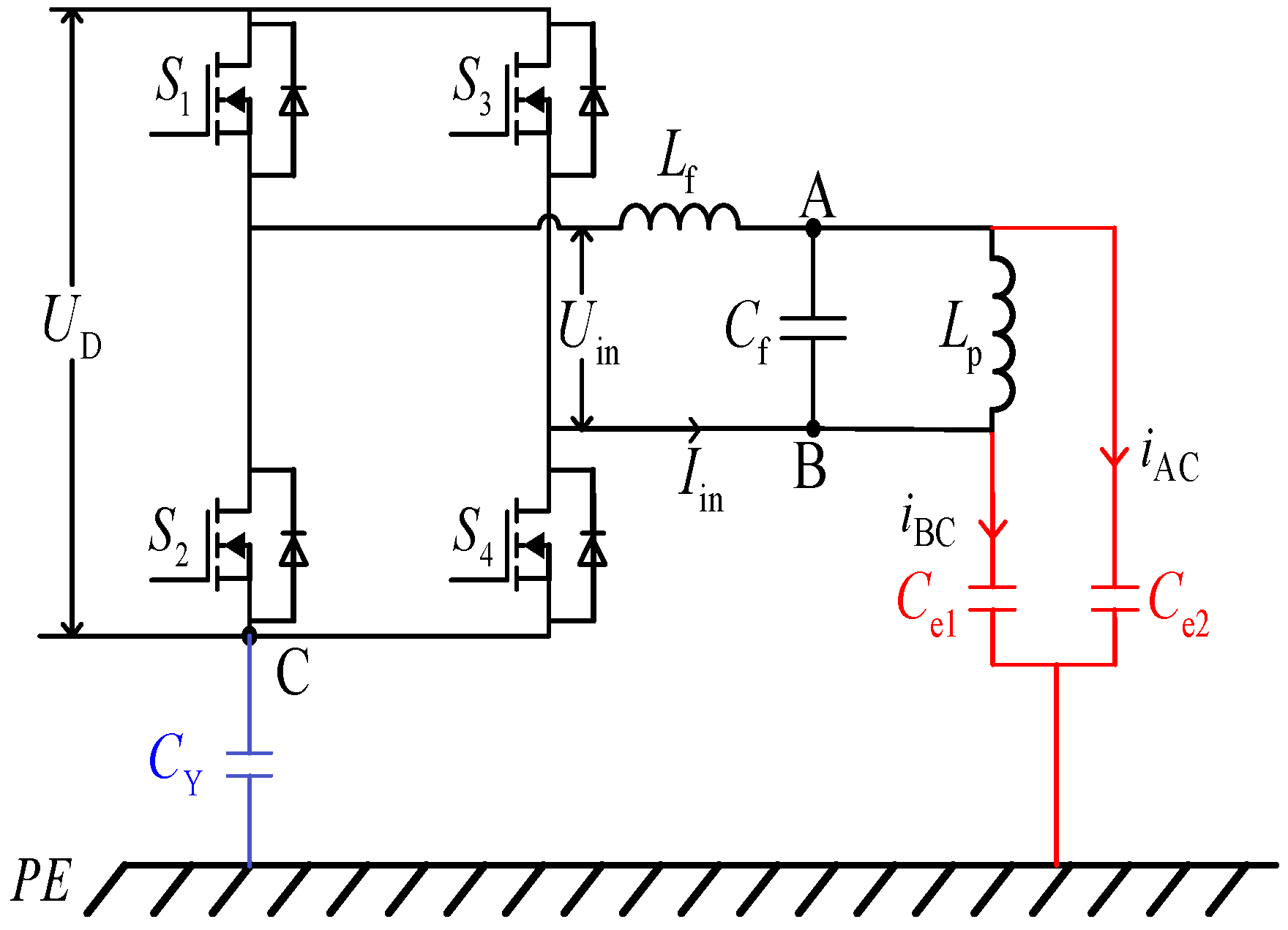
3. Analysis of Voltage to Earth

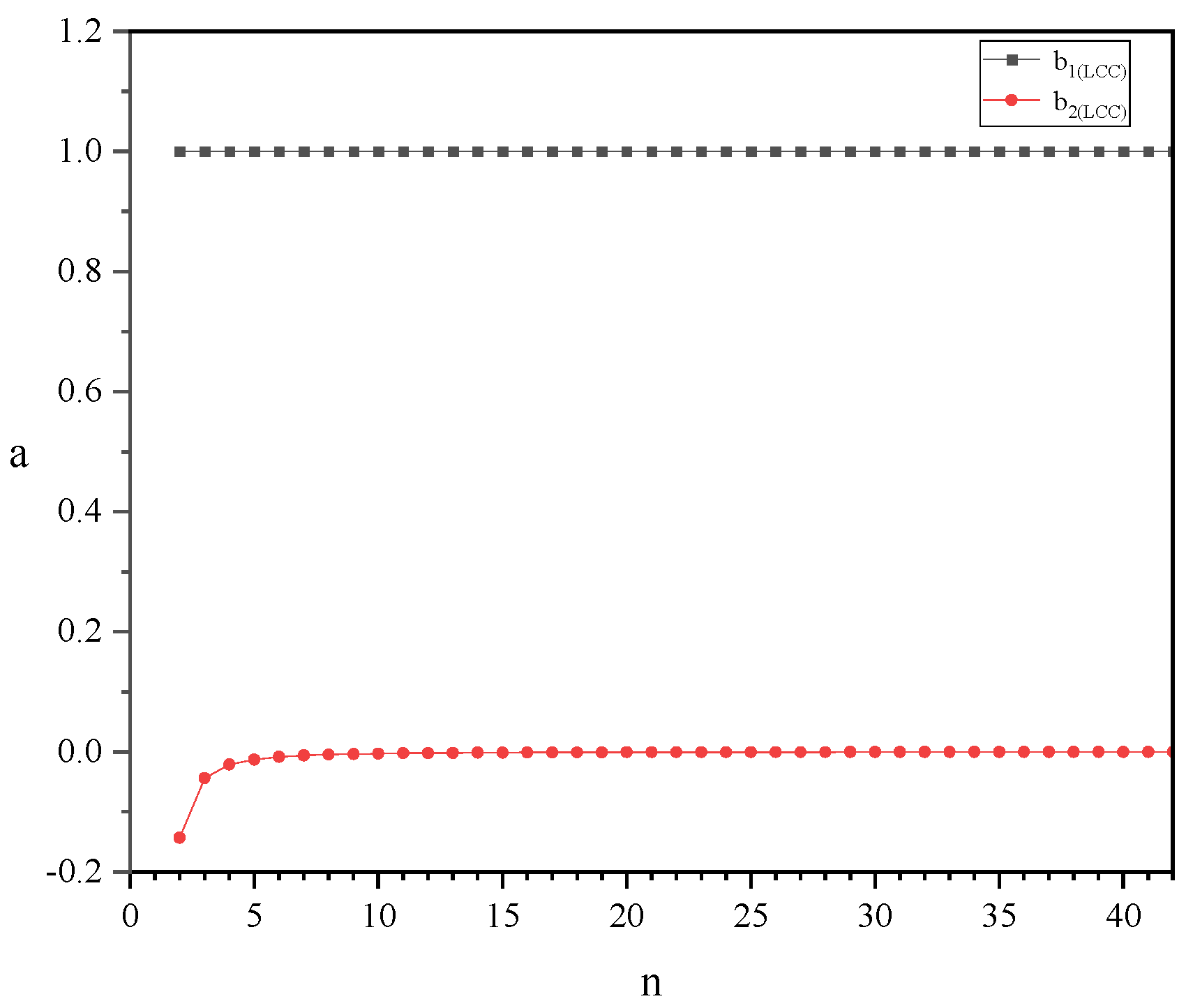
3.1. Theoretical Calculation

The theoretical analysis of the voltage to earth on the power rail mentioned above is conducted under the assumption of an unloaded condition at the transmitter of the DWPT system. Considering the influence of the load-side impedance on the voltage to earth of the power rail, the impedance RL at the load side is reflected back to the transmitter, as illustrated in Figure 8.
The load at the receiving end is reflected to the transmitter, and the expression of the impedance Z(2n−1) at the transmitter end is as follows:
Z ( 2 n 1 ) = j ω ( 2 n 1 ) L f 1 + 1 j ω ( 2 n 1 ) C f 1 ( R L + j ω n L P ) R L ( 2 n 1 ) + j ω ( 2 n 1 ) L P + 1 j ω ( 2 n 1 ) C f 1
The main parameters of the components at the transmitter and receiving ends of the DWPT system built in this experiment are shown in Table 1.
The first-order, third-order, fifth-order, and seventh-order impedances at the transmitter of the system are determined through calculations using Equation (16) and the parameter values provided in Table 1. The corresponding values are tabulated in Table 2.
To further analyze the harmonic differences in the voltage to earth between the unilateral compensation and bilateral compensation structures at the transmitter, the higher-order harmonic components in the voltage at points A and C are computed for both structures. The computation results are summarized in Table 3 and Table 4.
Based on the computation results provided in Table 3 and Table 4, the complex expressions of the fundamental voltage and higher-order harmonic voltages are subsequently transformed into trigonometric form. Using the obtained results, voltage waveform diagrams are plotted for points U AC , U AC , and U BC under both structures, as depicted in Figure 9.
According to the theoretical waveform of ground voltage shown in Figure 9, the waveform of the supply-rail-to-ground voltage U AC can be regarded as the vector sum of the square-wave voltage and sine-wave voltage when the transmitter adopts the unilateral compensation topology; the square-wave voltage comes from the supply-rail-to-ground voltage at the point B, while the sine-wave voltage is the voltage on the shunt compensation capacitor at the transmitter. The waveforms of both ground voltages U AC and U B C at both ends of the track tend to be more trigonometric when the LCC-type symmetric compensation topology is used. According to the Fourier analysis method, the square wave is composed of the fundamental of the waveform as a sine wave plus countless high (odd) harmonics; that is to say, the fewer the high harmonics, the more the waveform tends to be close to a sine wave. Comparing Figure 9a,b, it can be preliminarily demonstrated that the high harmonics in the ground voltage can be effectively reduced when using the LCC symmetrical compensation topology. Because the effect of the S-type symmetrical compensation topology at the receiver end to reduce the voltage to ground of the receiver coil is not obvious, the theoretical analysis waveforms are no longer given in this paper and are verified by the simulation waveforms below.

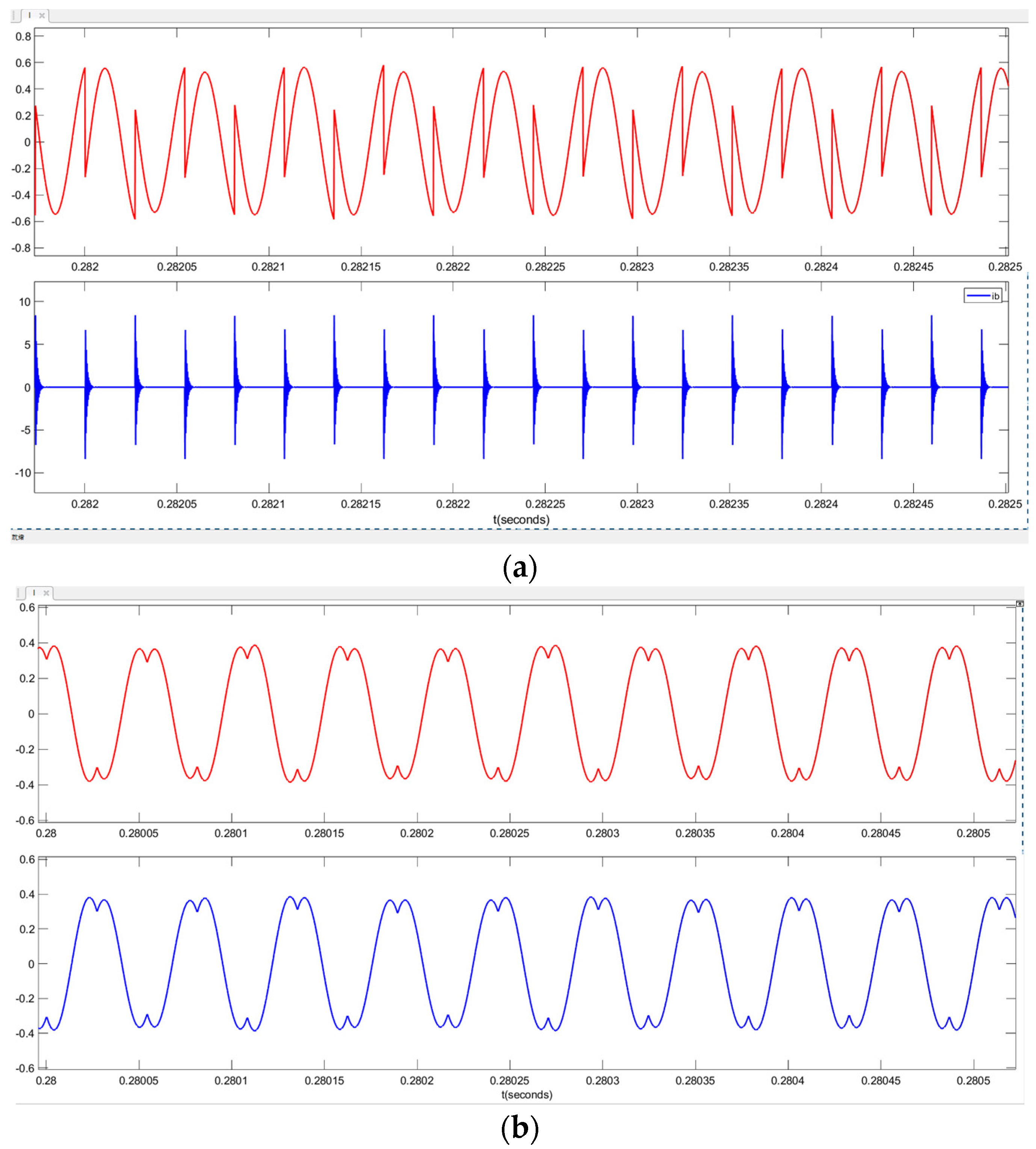
3.2. Simulation Verification

To accurately verify the reliability of the aforementioned theoretical analysis and computation, a DWPT system model based on the LCC-S topology was built using the Simulink module in MATLAB R2021a. The simulation results of the voltage waveforms are illustrated in Figure 10.
The power supply track model was simulated for the transmitter LCC resonant topology unilateral and symmetric compensation topology structure, respectively. The waveform and simulation results of U AC , U BC , U AC and U BC are shown in Figure 10 below. When the unilateral compensation topology was used, the leakage currents at both ends of the supply rail were represented by i AC and i BC . The simulated waveform of leakage current is shown in Figure 11. When symmetric compensation topology was used, the leakage currents at both ends of the supply rail were denoted by i AC and i BC . The simulated waveforms of leakage currents are shown in Figure 11.
According to Figure 10, it can be seen that the simulated waveform of U BC is a square waveform consistent with the voltage waveform of the voltage between BC as analyzed before, and the simulated waveform of U AC is likewise a superposition of a square waveform and a sinusoidal waveform. The simulated waveforms of U AC and U AC both approximate a sine wave. According to the principle of harmonic superposition, the simulated waveforms of U AC and U BC have a substantial (about 90%) reduction in high harmonic content as compared to the simulated waveforms of U AC and U BC . This preliminarily verifies the conclusion that the symmetrically compensated topology of LCC at the receiver end reduces the high harmonics of the supply-rail-to-ground voltage as analyzed in the previous section. According to Figure 11, it can be found that the simulated waveforms of both leakage currents i AC and i BC have current pulse spikes. With the sudden change of the voltage to ground, it will cause a large leakage current spike pulse. However, the simulated waveforms of leakage currents i BC and i BC are smoother, with less distortion and lower amplitude. This initially proves that the high harmonics in the voltage to ground are the main factor affecting the leakage current.

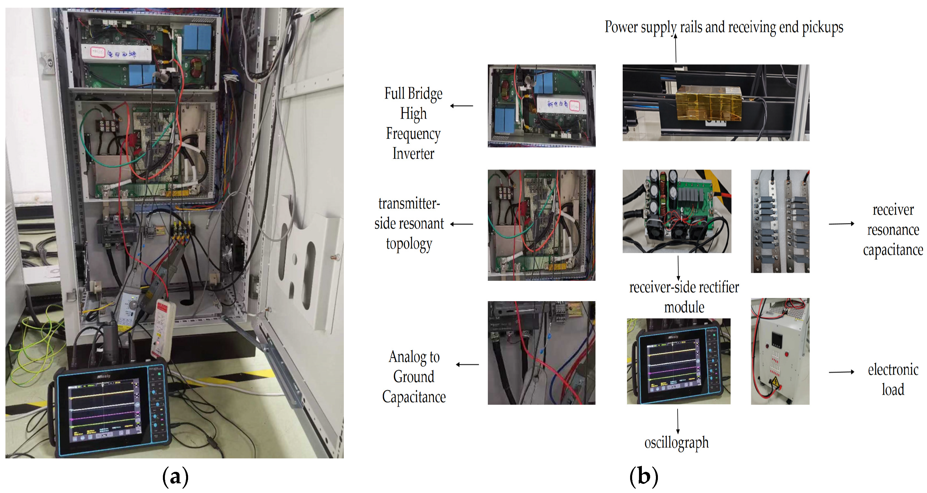
4. Experimental Testing

4.1. Experimental Platform

As shown in Figure 12, a DWPT experimental platform was built according to the LCC-S architecture. The experimental platform included a passive rectifier section on the grid side, a full-bridge high-frequency inverter and its control loop, an LCC resonance compensation structure on the transmitter side, a power supply rail, an E-type pickup, an S-type resonance compensation topology on the receiver side, a load on the receiver side, and an oscilloscope. The values of some of its component parameters are shown in Table 5.

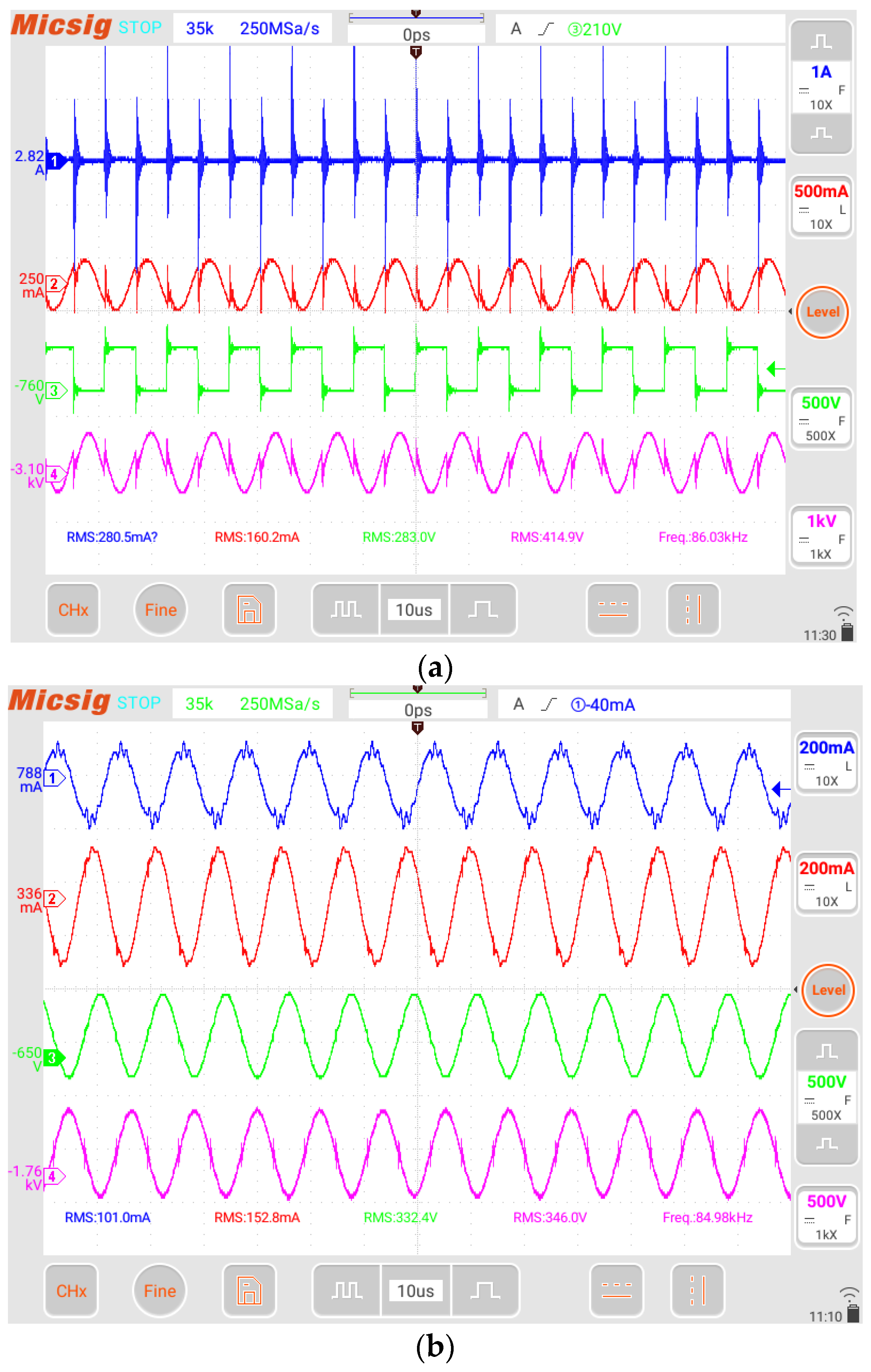
4.2. Experimental Results

Based on the DWPT experimental platform that was established, the waveforms of the leakage current and voltage to earth at the transmitter are measured separately for the unilateral compensation and bilateral compensation structures as depicted in Figure 13. The root mean square values of the voltage to earth and leakage current are listed in Table 5. The leakage current is represented as i AC , i BC , i AC , and i AC for the unilateral and bilateral resonant compensation topologies. In order to ensure the accuracy of the experimental results and the validity of the symmetrical compensation topology, the input DC bus voltage of the HF inverter is varied, and multiple sets of root–mean–square (RMS) values of the voltage to ground and leakage currents are collected and analyzed, as shown in Table 6a,b.
Through a comprehensive comparison of the theoretical derivation, simulation modeling, and experimental measurement of the voltage-to-earth waveform in the power supply rail, it can be observed that the voltage-to-earth waveforms obtained from theoretical derivation, simulation, and measurement show a similar trend. Nevertheless, it should be noted that the theoretical analysis and simulation model may have idealized assumptions by neglecting the resonance inductance and internal resistance of the transmitting rail, which might lead to deviations in the amplitude of the voltage-to-earth waveform in the three scenarios.
Based on Equation i = Cdu/dt, the magnitude and direction of the leakage current are determined by the rate of change of the voltage to earth with respect to time. Therefore, in the case of the unilateral resonant compensation topology adopted at the transmitter, the measured value of U BC exhibits larger peak pulses during the closing and opening of the inverter circuit, resulting in the presence of significant peak currents in the waveform of i BC . It is due to the high-voltage pulsation dv/dt generated by the power switching devices in the high-frequency inverter circuits at the instant of disconnection and closure, and the high-voltage pulsation dv/dt during the switching period generates a leakage current, which flows from the transmitter side of the WPT to the earth through the parasitic capacitance [22]. Therefore, this high-voltage pulsation dv/dt leads to a large leakage current pulsation in the leakage current i BC measured at point B when the single-side compensation topology is used. Because the main consideration of this paper is the suppression effect of the compensation structure on the leakage currents, the disturbances generated by the power switching of the high-frequency inverter are not further elaborated in detail in this paper. Furthermore, the adoption of the unilateral resonant compensation topology at the transmitter introduces higher harmonic components in U AC and U BC , leading to relatively higher root–mean–square values measured for i AC and i BC .
However, when the bilateral resonant compensation topology is adopted at the transmitter, both the waveforms of U AC and U BC tend to resemble triangular function waveforms. This indicates a significant reduction in the higher harmonic content in U AC and U BC and an effective improvement in waveform distortion. Moreover, the similar root–mean–square values of U AC and U BC preliminarily demonstrate that the ground impedance at both ends of the transmitting rail is the same when the bilateral resonant compensation topology is employed. Compared to U AC , the root–mean–square value of U AC significantly decreases, and the waveform distortion improves noticeably. Therefore, the root–mean–square value of i AC decreases, and the waveform distortion improves noticeably. Compared to U BC , the root–mean–square value of U BC slightly increases, but the overall waveform of U BC is smoother with minimal voltage transients. As a result, the root–mean–square value of i BC significantly decreases, and the waveform distortion improves noticeably. Based on the RMS values of supply rail voltage to ground and leakage current measured in Table 6a,b for two different compensation structures, it can be found that the RMS values of U AC and U AC are smaller than those of U AC and U BC , respectively, and that the RMS value of the leakage current i BC is substantially lower than that of i BC for the same bus voltage of the high-frequency inverter in addition to the positive correlation between the voltage to ground and the leakage current. The effectiveness of suppressing the magnitude of leakage current by suppressing the high harmonics of the voltage to ground has been demonstrated, and the flowchart of the research methodology is provided in Figure 14.

5. Conclusions

This paper primarily focuses on the investigation of voltage to earth and leakage current at the transmitter of the DWPT system. The causes of leakage current generation and its conduction paths are analyzed. Based on the LCC-S resonant topology structure, circuit models for single and bilateral resonant compensation topologies at the transmitter are established, and the Fourier series expansion of the voltage to earth in the power supply rail is derived. The simulation results initially validate the fact that the LCC symmetric compensation topology at the transmitter side can effectively reduce more than 90% of the high harmonics in the ground voltage and reduce the distortion degree of the ground voltage and leakage current, and the waveforms of the coil ground voltage and leakage current are experimentally measured when the transmitter side adopts the unilateral compensation topology and symmetric compensation topology. The experiment verified that the symmetrical compensation topology can effectively reduce the high harmonics of the ground voltage at both ends of the supply rail by more than 90%, the waveforms of the ground voltage at both ends tend to be balanced, the degree of distortion is greatly reduced, and the degree of distortion and the root–mean–square (RMS) value of the leakage current waveform at the transmitter end are significantly improved as compared to that in the case of the single-sided compensation topology. When the symmetric compensation topology is used at the receiver side, as compared to the unilateral compensation topology, the voltage waveforms at both ends of the receiver coil to ground are more balanced, and the RMS value of the leakage current is reduced by about 10%. This experiment verifies the effectiveness of the LCC-S symmetric compensation topology for suppressing leakage current. The results demonstrate that the adoption of the bilateral resonant compensation topology effectively eliminates higher harmonic components in the voltage-to earth-waveform, thereby reducing the magnitude of the leakage current, and demonstrating that the improvement of energy transfer efficiency and reduction of energy loss lead to improved performance and the stability of dynamic vehicle charging systems. The correctness of the theoretical analysis is verified through simulation modeling and experimental testing.
In this paper, the parasitic capacitance of the high-frequency inverter at the transmitting end, the parasitic capacitance of the power supply rail, and the parasitic capacitance between the power supply rail and the receiving coil are neglected in the analyzing process, and the conducted electromagnetic interference caused by the system is ignored. The leakage current situation at the receiving end of the long-rail dynamic WPT system, the relationship between the leakage current and the number of loads in operation, and the cross-coupling between the loads have not been considered. In future works, it will be necessary to explore other methods of conducted EMI from parasitic capacitance and the immunity of receiver side, multi-load dynamic WPT systems.

Author Contributions

Conceptualization, S.H., B.Z. and Y.H.; methodology, Y.H.; software, S.H., B.Z., X.S., T.Z. and X.Z.; validation, S.H., B.Z. and Y.H.; formal analysis, S.H. and B.Z.; investigation, S.H. and B.Z; resources, Y.H.; data curation, S.H., B.Z. and Q.S.; writing—original draft preparation, S.H.; writing—review and editing, S.H., B.Z. and T.Z.; visualization, S.H.; supervision, Y.H. and B.Z.; project administration, Y.H.; funding acquisition, Y.H. All authors have read and agreed to the published version of the manuscript.

Funding

This research was funded by the Energy Research Institute of Shandong Academy of Sciences (grant number 2022TSGC2075 and 2022TSGC2350). The APC was funded by Yanjin Hou.

Data Availability Statement

The original contributions presented in the study are included in the article, further inquiries can be directed to the corresponding author.

Conflicts of Interest

The authors declare no conflicts of interest.

References

  1. Basir, A.; Yoo, H. Efficient Wireless Power Transfer System with a Miniaturized Quad-Band Implantable Antenna for Deep-Body Multitasking Implants. IEEE Trans. Microw. Theory Tech. 2020, 68, 1943–1953. [Google Scholar] [CrossRef]
  2. Boys, J.T.; Covic, G.A. The Inductive Power Transfer Story at the University of Auckland. IEEE Circuits Syst. Mag. 2015, 15, 6–27. [Google Scholar] [CrossRef]
  3. Liu, W.; Chau, K.T.; Chow, C.C.T.; Lee, C.H.T. Wireless Energy Trading in Traffic Internet. IEEE Trans. Power Electron. 2021, 37, 4831–4841. [Google Scholar] [CrossRef]
  4. Geng, Y.; Li, B.; Yang, Z.; Lin, F.; Sun, H. A High Efficiency Charging Strategy for a Supercapacitor Using a Wireless Power Transfer System Based on Inductor/Capacitor/Capacitor (LCC) Compensation Topology. Energies 2017, 10, 135. [Google Scholar] [CrossRef]
  5. Hou, Y.; Sun, S.; Liu, Z.; Wei, X.; Qiao, S.; Feng, G.; Zhang, B. Wireless power transfer system based on LCC/LCL-S variable structure with constant output power. Energy Rep. 2022, 8, 850–862. [Google Scholar] [CrossRef]
  6. Hou, Y.; Feng, G.; Liu, Z.; Wei, X.; Qiao, S.; Luo, X.; Ding, R.; Sun, S.; Zhang, B. Research on Dual-LCC MCRWPT system based on controlled rectifier. Energy Rep. 2022, 8, 823–836. [Google Scholar] [CrossRef]
  7. CLiu, C.; Hu, A.P.; Wang, B.; Nair, N.-K.C. A Capacitively Coupled Contactless Matrix Charging Platform with Soft Switched Transformer Control. IEEE Trans. Ind. Electron. 2011, 60, 249–260. [Google Scholar] [CrossRef]
  8. Mohamed, A.A.; Shaier, A.A.; Metwally, H.; Selem, S.I. An Overview of Dynamic Inductive Charging for Electric Vehicles. Energies 2022, 15, 5613. [Google Scholar] [CrossRef]
  9. Choi, S.Y.; Jeong, S.Y.; Gu, B.W.; Lim, G.C.; Rim, C.T. Ultraslim S-Type Power Supply Rails for Roadway-Powered Electric Vehicles. IEEE Trans. Power Electron. 2015, 30, 6456–6468. [Google Scholar] [CrossRef]
  10. Tian, Y.; Sun, Y.; Su, Y.; Wang, Z.; Tang, C. Neural Network-based Constant Current Control of Dynamic Wireless Power Supply System for Electric Vehicles. Inf. Technol. J. 2012, 11, 876–883. [Google Scholar] [CrossRef]
  11. Lee, S.; Huh, J.; Park, C.; Choi, N.S.; Cho, G.H.; Rim, C.T. On-Line Electric Vehicle using inductive power transfer system. In Proceedings of the 2010 IEEE Energy Conversion Congress and Exposition, Atlanta, GA, USA, 12–16 September 2010; pp. 1598–1601. [Google Scholar]
  12. Liang, Z.; Jiang, Y. Calculation of Electric Field Under High Voltage Direct Current Transmission Lines by the Upstream Finite Element Method. In Proceedings of the 2020 IEEE 8th International Conference on Computer Science and Network Technology (ICCSNT), Dalian, China, 20–22 November 2020; pp. 46–49. [Google Scholar]
  13. Campi, T.; Cruciani, S.; Maradei, F.; Feliziani, M. Conducted emission of wireless power transfer charging system in electric vehicle. In Proceedings of the 2017 IEEE International Symposium on Electromagnetic Compatibility & Signal/Power Integrity (EMCSI), Washington, DC, USA, 7–11 August 2017; pp. 619–622. [Google Scholar]
  14. Xiao, T.; Chen, W.; Qi, H.; Zhao, Z.; Sha, Y. Conducted EMI analysis of double-side LCC compensated WPT system. In Proceedings of the 2017 Sixth Asia-Pacific Conference on Antennas and Propagation (APCAP), Xi’an, China, 16–19 October 2017; pp. 1–3. [Google Scholar]
  15. Mei, Y.; Wu, J.; He, X.; Zhang, H.; Lu, F. Study on Parasitic Capacitance Effect in High Power Inductive Power Transfer System. In Proceedings of the 2019 IEEE Energy Conversion Congress and Exposition (ECCE), Baltimore, MD, USA, 29 September–3 October 2019; pp. 129–134. [Google Scholar]
  16. Mei, Y.; Wu, J.; He, X. Common Mode Noise Analysis for Inductive Power Transfer System Based on Distributed Stray Capacitance Model. IEEE Trans. Power Electron. 2021, 37, 1132–1145. [Google Scholar] [CrossRef]
  17. Song, C.; Kim, H.; Kim, Y.; Kim, D.; Jeong, S.; Cho, Y.; Lee, S.; Ahn, S.; Kim, J. EMI Reduction Methods in Wireless Power Transfer System for Drone Electrical Charger Using Tightly Coupled Three-Phase Resonant Magnetic Field. IEEE Trans. Ind. Electron. 2018, 65, 6839–6849. [Google Scholar] [CrossRef]
  18. Park, J.; Shin, Y.; Kim, D.; Park, B.; Ahn, S. Planar Resonance Reactive Shield for Reducing the EMI in Portable WPT Device Application. In Proceedings of the 2018 IEEE Symposium on Electromagnetic Compatibility, Signal Integrity and Power Integrity (EMC, SI & PI), Long Beach, CA, USA, 30 July–3 August 2018; pp. 419–422. [Google Scholar]
  19. Kerekes, T.; Teodorescu, R.; Liserre, M.; Klumpner, C.; Sumner, M. Evaluation of Three-Phase Transformerless Photovoltaic Inverter Topologies. IEEE Trans. Power Electron. 2009, 24, 2202–2211. [Google Scholar] [CrossRef]
  20. Arai, N.; Toriumi, Y.; Okamoto, K.; Kato, J.; Akiyama, Y.; Sasaki, K. Unsymmetric voltage of conducted noise measurement system without grounding by estimation of ground capacitance. IEEE Trans. Instrum. Meas. 2021, 70, 1–7. [Google Scholar] [CrossRef]
  21. Qi, T.; Sun, J. DC bus grounding capacitance optimizatio for common-mode EMI minimization. In Proceedings of the 2011 Twenty-Sixth Annual IEEE Applied Power Electronics Conference and Exposition (APEC), Fort Worth, TX, USA, 6–11 March 2011; pp. 661–666. [Google Scholar]
  22. Xiao, T.; Chen, W.; Yang, Y.; Dai, L.; Wang, R. Conducted EMI Modeling and Filtering for Multi-load Magnetic Resonant WPT System. In Proceedings of the 2018 IEEE International Power Electronics and Application Conference and Exposition (PEAC), Shenzhen, China, 4–7 November 2018; pp. 1–6. [Google Scholar]
Figure 1. Circuit model of LCC-S−type DWPT system.
Wevj 15 00225 g001
Figure 2. Equivalent model of the transmitter supply rail.
Wevj 15 00225 g002
Figure 3. Equivalent circuit model at the transmitter.
Wevj 15 00225 g003
Figure 4. Transmitter-to-ground capacitance model.
Wevj 15 00225 g004
Figure 5. Bilateral resonance compensation topology.
Wevj 15 00225 g005
Figure 6. Trends in a 1 and a 2 with n.
Wevj 15 00225 g006
Figure 7. Trends in b 1 and b 2 with n.
Wevj 15 00225 g007
Figure 8. Equivalent circuit of reflected impedance at the transmitter.
Wevj 15 00225 g008
Figure 9. Theoretical waveform of voltage to ground. (a) Unilateral resonant topology: UAC (Green). (b) Bilateral resonant topology: U AC (Green) and U BC (Blue). (Y-axis: amplitude. X-axis: time).
Wevj 15 00225 g009
Figure 10. Simulated waveform of voltage to ground. (a) Unilateral resonant topology: UAC (Green) and U BC (Blue). (b) Bilateral resonant topology: U AC (Green) and U BC (Blue). (Y−axis: amplitude. X−axis: time).
Wevj 15 00225 g010
Figure 11. Simulated waveform of leakage currents to ground. (a) Unilateral resonant topology: iAC (Red), i BC (Blue). (b) Bilateral resonant topology: i AC (Red), i BC (Blue). (Y-axis: amplitude. X-axis: time).
Wevj 15 00225 g011
Figure 12. The DWPT experimental platform. (a) Experimental platform, and (b) experimental setup.
Wevj 15 00225 g012
Figure 13. Experimental measurement waveforms of leakage current and voltage to earth. (a) Unilateral resonant topology: U AC (Purple), i AC (red), U BC (green), and iBC (blue). (b) Bilateral resonant topology: U AC (Purple), i AC (Red), U BC (Green), and i BC (Blue).
Wevj 15 00225 g013
Figure 14. Research methodology flowchart.
Wevj 15 00225 g014
Table 1. DWPT system main parameters.
ParametersSymbolValue
Transmitter coil inductance [µH]Lp26
Receiver coil inductance [µH]Ls294.7
Primary side compensation inductance [µH]Lf26
Primary side parallel compensation capacitance [nF]Cf134.8
Secondary side compensation inductance [nH]Cs11.9
Resonant frequency [kHz]fs85
mutual inductance [µF]M16.763
Load [Ω]RL10
Table 2. Higher-order impedance calculations.
OrderImpedance Value (Ω)
Z124.057
Z37.032 × 10−4 + 36.422j
Z56.609 × 10−5 + 66.532j
Z71.582 × 10−5 + 95.174j
Table 3. Calculations of the values of the voltage to earth (unilateral resonant topology).
OrderUAC (V)UBC (V)
U 1 255.079–259.833i255.079 + 250
U 3 −96.595–3.313i × 10−375.026 + 250
U 5 −48.937–9.344i × 10−545.016 + 250
U 7 −33.524–1.092i × 10−532.154 + 250
Table 4. Calculations of the values of the voltage to earth (bilateral resonant topology).
Order U AC (V) U BC (V)
U 1 225.079–129.916i225.079–129.916i
U 3 −10.784–1.657i × 10−3−10.784–1.654i × 10−3
U 5 −1.961–4.677i × 10−5−1.961–4.677i × 10−5
U 7 −0.685–5.458i × 10−6−0.685–5.458i × 10−6
Table 5. DWPT system experiment platform part of the parameters.
ParametersSymbolValue
Transmitter coil inductance [µH]Lp26
Receiver coil inductance [µH]Ls294.7
Primary side compensation inductance [µH]Lf26
Primary side parallel compensation capacitance [nF]Cf2.84
Secondary side compensation inductance [nH]Cs251
Supply rail coil internal resistance [Ω]Rp0.06
Receiving coil internal resistance [Ω]Rs0.008
Load [Ω] R L 10
Table 6. Root–mean–square (RMS) values of current and voltage. (a) Unilateral resonant topology. (b) Bilateral resonant topology.
(a) Unilateral Resonant Topology.
U AC i AC U BC i BC
351.0 V129.5 mA234.0 V204.5 mA
385.0 V142.5 mA257.0 V249.1 mA
414.0 V160.2 mA283.0 V280.5 mA
453.0 V179.6 mA311.0 V314.8 mA
(b) Bilateral Resonant Topology.
U AC i AC U BC i BC
275.0 V124.0 mA273.0 V80.5 mA
312.0 V130.5 mA300.0 V89.1 mA
346.0 V158.2 mA332.0 V101.0 mA
381.0 V160.5.6 mA358.0 V112.2 mA
Disclaimer/Publisher’s Note: The statements, opinions and data contained in all publications are solely those of the individual author(s) and contributor(s) and not of MDPI and/or the editor(s). MDPI and/or the editor(s) disclaim responsibility for any injury to people or property resulting from any ideas, methods, instructions or products referred to in the content.

