1. Introduction
Reducing greenhouse gas emissions from the transport sector, increasing fuel efficiency, and bringing environmentally friendly vehicles to the market have become the main objectives of the car industry [
1]. Consequently, the hybridisation of conventional vehicles presents a variety of potential avenues for enhancing the vehicle’s fuel efficiency. These include storing braking energy in the battery for later use for propulsion [
2,
3], utilising engine power at higher efficiency zones, and otherwise using the electric motor for propulsion. Furthermore, the integration of an electric motor enables a reduction in the size of the engine, thereby enhancing efficiency through the operation in higher load ranges [
4].
Optimising the size of powertrain components [
5,
6] and developing efficient control logic for power distribution [
7] between the engine and the electric motor, while taking into account the vehicle architecture, powertrain dynamics, and power source characteristics, can significantly improve HEV fuel efficiency.
There is extensive literature on the HEV controller design [
8,
9,
10,
11]. In the literature, two main groups of control strategies are used to develop EMS for HEVs [
7]. These are the rule-based (RBCS) and the optimisation-based control strategies (OBCS). The RBCS is a relatively basic control strategy that is simple to implement, as it employs a series of static predetermined rules to manage the power split between the sources [
12]. The rules are established by the experience of the engineers. The RBCS relies upon a series of static parameters to select driving modes, rendering it less adaptable to dynamic changes in the driving context [
13]. Conversely, the OBCS provides an optimal power split and utilises a cost function that is minimised over a constrained range. This results in a fast response to varying vehicle operating states. The OBCS can be further categorised into two sub-types: the Global Optimisation Control Strategy (GOCS) and the Instantaneous Optimisation Control Strategy (IOCS). The GOCS provides an optimal global solution for a defined driving scenario, but this solution requires a high computing time and memory, and it is only applicable when the complete driving scenario is known in advance [
14]. As a consequence, it cannot be used as a real-time control strategy; rather, its solution can serve as a benchmark to improve existing online controls [
15]. On the contrary, the IOCS minimises the cost function at every time instant [
16]. This makes IOCS an online, thus a real-time, regulator, and provides a local minimum solution. One of the widely used methods to solve the instantaneous optimisation problem is the Equivalent Consumption Minimisation Strategy (ECMS). Paganelli et al. [
17] were the first to use an ECMS as an EMS of the HEV. ECMS aims at minimising the total amount of equivalent fuel use, including the fuel consumed by the engine and the virtual amount of fuel used by EM. It is necessary to constrain the cost function considering the operating limits of the power sources and the fulfilment of the driver’s power requirements. To ensure battery operation in charge-sustaining mode, an s-shaped penalty function is often used [
18].
To determine the optimum power distribution between the combustion engine and the electric motor(s), models based on a forward or backward approach are used [
19,
20]. Both models take into account the equations of longitudinal vehicle dynamics. The traction or braking torque required to accelerate or decelerate the vehicle is calculated from the speed profile of the drive cycle. These values are then used in the controller to identify the optimal torque distribution [
10,
11]. Commonly employed optimisation-based control strategies, such as dynamic programming and equivalent consumption minimisation, seek to minimise a cost function that includes the torque of the internal combustion engine (ICE) and the battery state of charge [
19,
21,
22]. In these control strategies, the inertia effect of the flywheel and crankshaft is either neglected [
8,
9] or considered within the vehicle’s apparent mass [
21].
Certainly, the engine generates additional torque to overcome its own inertia, mainly composed of the inertia of the crankshaft and flywheel. Thus, the inclusion of the inertia effect of the crankshaft and flywheel in the controller serves to precisely estimate the engine’s actual operating point in its characteristic map. This leads to further improved distribution of the torque demand. Several works can be found in the literature that are dedicated to the accurate estimation of the actual fuel consumption of the engine by optimising the torque or the power split. In [
23,
24], the precision of HEV fuel economy calculation was improved by integrating a transient behaviour of the engine. Moreover, by incorporating the engine transient behaviour in the controller, the reduction in its transient operation was achieved, resulting in more stable operation. This transient behaviour of the engine is influenced by a combination of factors, and it is difficult to isolate each effect and establish accurate analytical relationships [
25].
Pam et al. [
26] demonstrated the effect of the inertia of the rotating components of the vehicle, including the wheels, the inertia of the engine, and the EM on the estimation of the fuel consumption for P2 hybrid vehicles. Four different cases were compared. Dynamic programming was used as the control strategy, as it allows convergence to an optimal solution for each case. These cases include performing simulations with different vehicle masses, such as (i) static vehicle mass (i.e., neglecting rotating inertia), (ii) dynamic mass (taking into account the gear ratio change), (iii) average gear ratio, and (iv) average mass at different gear ratios. The results showed that the fuel consumption error can be in the range of 0.25–11.1% (the higher value corresponds to the static mass) when compared to the dynamic gear change case.
The works that consider the transient operation of the engine [
23,
25,
27,
28] mainly apply transient correction factors to quasi-static fuel consumption [
23,
27] determined by extensive experimental data [
25].
Different from vehicles driven by only ICE, the constant addition of engine inertia may introduce some error in the estimation of the torque requirements for the HEV. This is because the effect of the engine and electric motor exists only in their respective operating modes. When one of the power sources is disengaged, its inertia should not affect the total mass of the vehicle. Consequently, the work defining the influence of engine inertia on the fuel consumption of HEV can be considered a valid and meaningful actual contribution to the field.
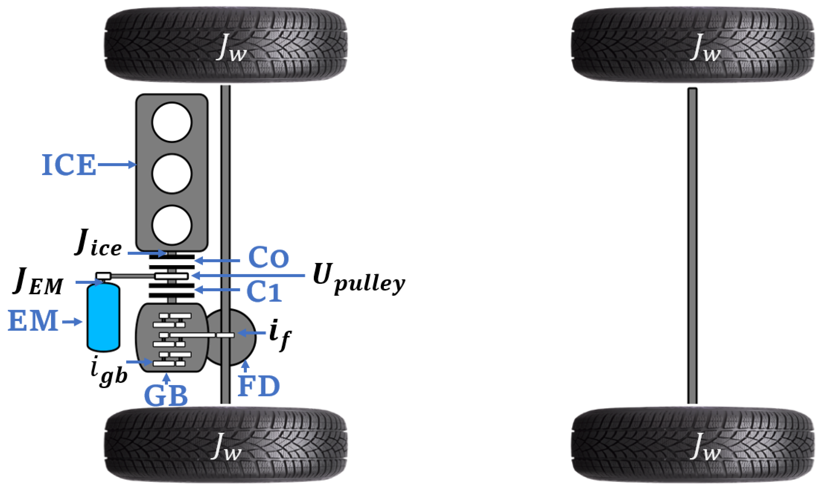
In this paper, mid-size two clutch P2 HEV with off-centre EM configuration was employed (see
Figure 1). In the off-centre layout, the EM is connected to the input shaft of the gearbox through the belt drive.) In the P2 configuration, the resistive effect of the engine during braking phases can be bypassed, as the engine can be decoupled through the use of a clutch
between the internal combustion engine (ICE) and the electric motor (EM). This allows the EM to accumulate more energy during regenerative phases.
The developed vehicle simulator model considers the inertia of the entire powertrain components, i.e., from power sources to the wheels. This includes inertias of EM, ICE and four wheels. The torque split is implemented based on the required torque and speed at the input of the gearbox. Therefore, torque split optimisation can only be affected by the dynamics of the rotating components of power sources. The inertia of the crankshaft and flywheel is considerably higher than the rotary inertia of EM. Thus, the objective of this study is to demonstrate the influence of incorporating the engine inertia into the controller’s cost function, while maintaining the vehicle performance model unchanged. It can be postulated that the incorporation of EM inertia into the cost function may result in a marginal enhancement of the torque split, although this may be accompanied by an increase in the complexity of the optimisation problem in the controller. Consequently, this paper is constrained to the consideration of engine inertia in the cost function of the controller.
The work adopts the ECMS as a control strategy due to its practical advantages, which take into account the inertial effect of the engine flywheel and crankshaft, as these components are critical in determining torque demand. The omission of consideration of these factors can result in inaccurate calculations and sub-optimal performance of the torque split controller. Consequently, this paper addresses two key objectives: firstly, to quantify the impact of crankshaft and flywheel inertia on fuel consumption in conventional vehicles; and secondly, to develop an optimisation-based controller for hybrid electric vehicles (HEVs) that accounts for the inertia effect of rotational components of the engine.
The remainder of the paper is structured as follows.
Section 2 is devoted to quantifying the impact of engine inertia on fuel consumption calculation in conventional ICE driving conditions.
Section 3 outlines the influence of engine inertia in HEVs and presents an EMS designed to minimize this effect. The subsequent section involves a comparison of the obtained results with and without engine inertia. The conclusion summarizes the work and highlights the results obtained in this study.
2. Modelling the Vehicle Performance
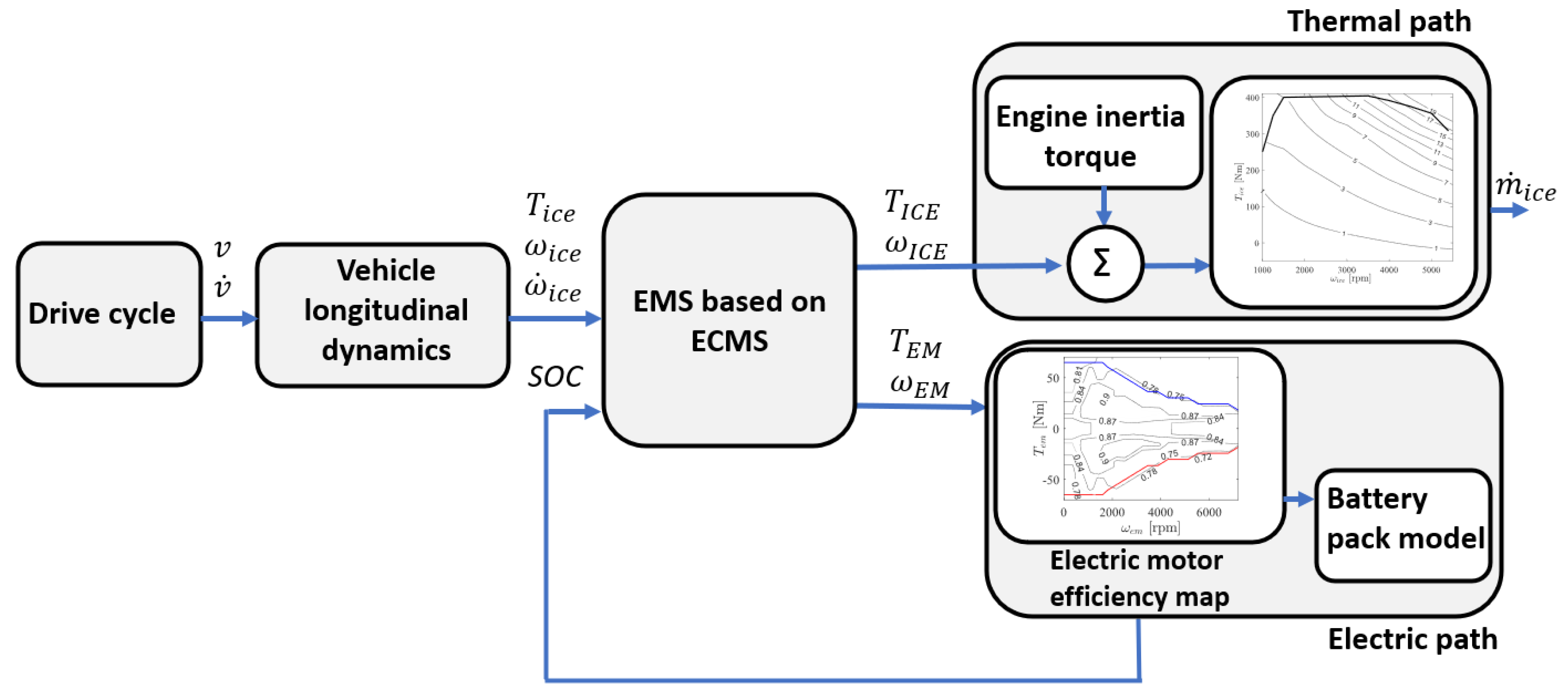
A backward approach [
19,
20,
22,
29] was used to develop a vehicle simulator model for both a conventional vehicle and a P2 off-axis HEV (see
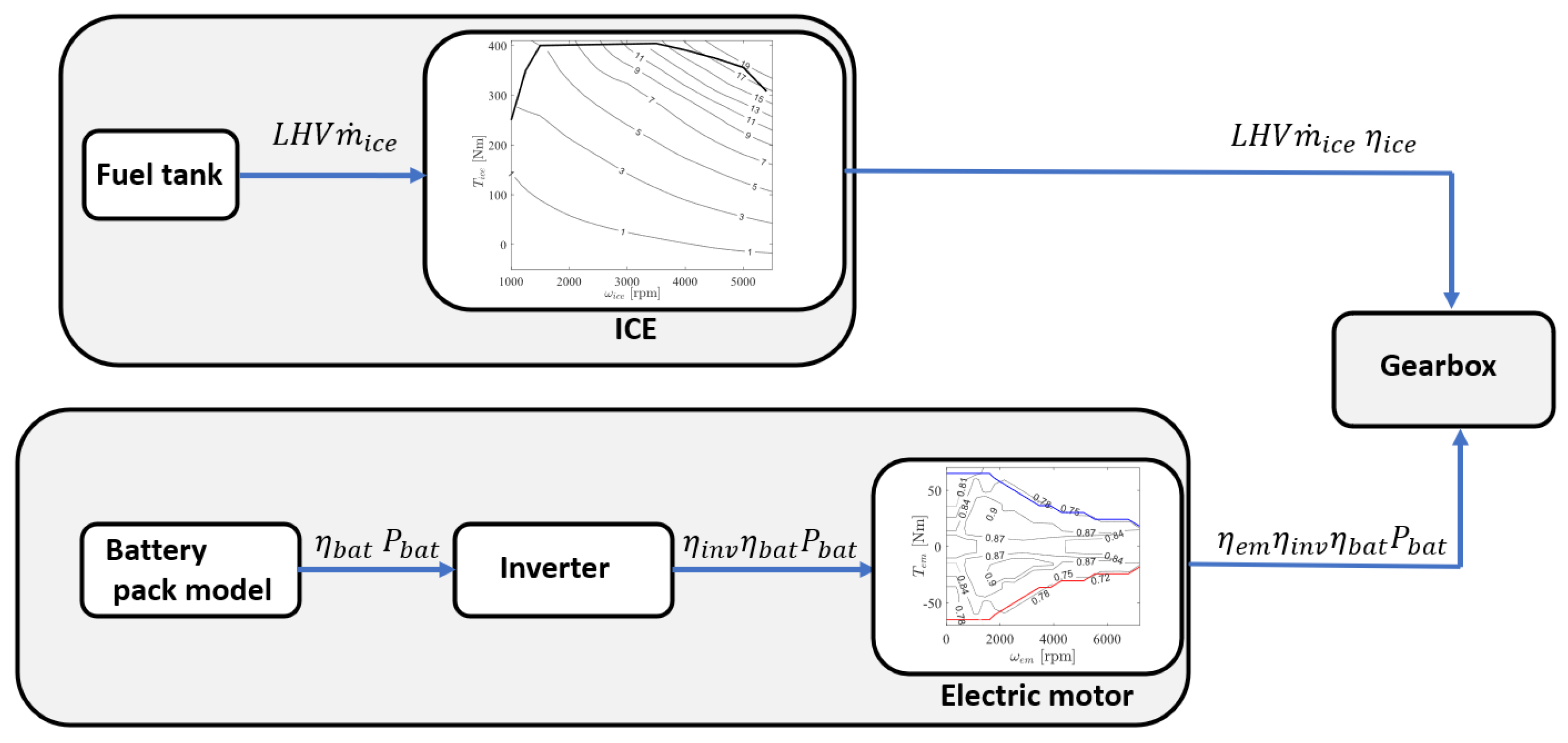
Figure 2). The required torque output to move the vehicle on a given driving profile is calculated from the required vehicle speed, taking into account the vehicle architecture and the mechanical couplings in the powertrain. For the conventional vehicle simulation, only the thermal path depicted in
Figure 2 is selected.
To follow the required speed profile
, it is necessary to overcome vehicle inertia forces, the rolling resistance of the tyres, and the force of the aerodynamic drag. Therefore, the traction force
on the wheel can be calculated as follows:
where
M is the vehicle static mass, kg;
is the vehicle longitudinal acceleration, m/s
2;
g is the the gravitational constant, m/s
2;
is the tire rolling resistance coefficient, −;
is the air density, kg/m
3;
is the aerodynamic drag coefficient, −;
v is the vehicle longitudinal speed, m/s; and
is the frontal area of the vehicle, m
2.
The tire model then converts the vehicle’s linear velocity
v, acceleration
, and required tractive force
into axle rotational velocity (
), angular acceleration (
), and required torque (
), respectively. It should be noted that the rotational inertia of four wheels
is added to the torque required for the traction [
19,
22]:
where,
is the active radius of the tire that has been calculated from tire specifications [
30]
and
.
The transmission model consists of a mathematical representation of a six-speed gearbox, final gear, and differential. The inputs and outputs of the transmission model are interlinked as described in Equation (
3). The required torque
is then split between ICE and EM [
29]:
where
is the final gear ratio,
is the transmission efficiency of the final gear,
is the gear ratio of the gearbox, and
is the transmission efficiency of the gearbox.
3. Influence of Engine Inertia on Fuel Consumption of the Conventional Vehicle
The internal combustion engine model is based on open-source data from the Environmental Protection Agency for the 2016 Mazda CX9 2.5L Skyactive gasoline engine [
31]. The main specifications of the vehicle are listed in
Table 1. The conventional backward model has been validated using experimental results of the vehicle on the dynamometer by Argonne National Laboratory and is publicly available on [
32]. The simulation model of the conventional vehicle comprises a number of subsystems, including the drive cycle, which defines the reference vehicle speed and acceleration; the vehicle dynamics, which are used to calculate the forces that resist vehicle motion; the transmission, which changes the values of torque and angular speed based on the speed ratio of the engaged gear; and the engine subsystem, which is modelled as a static map to compute the fuel consumption. The readers are respectfully requested to refer to previously published authors’ paper [
29] for a comprehensive description of the model and its experimental validation.
As stated earlier, the required engine output torque (
is the torque generated at the input shaft of the gearbox to overcome resistance forces and the wheels’ inertia) and angular velocity are calculated using the backward model based on the drive cycle request. In a further step, in addition to the required torque, the engine model calculates the torque needed to overcome the inertia of the rotating parts by multiplying the inertia of the crankshaft and flywheel
by the rotational acceleration of the crankshaft
. Thus, the engine’s actual torque (
including inertia torque of engine rotary components) is calculated as follows:
In this model, the P2 configuration is employed; thus, the resistive effect of the engine during braking phases can be avoided by the presence of a clutch between the flywheel and transmission. Consequently, in this configuration, the engine’s output torque is either considered as zero or a positive value. When the engine does not contribute to propelling the vehicle (
equals zero), it is decoupled from the transmission. In such cases, there is no need to account for engine inertia torque (the engine may be switched off or idling). However, if the engine remains connected to the transmission and provides torque for vehicle propulsion (
equals 1), the engine inertia torque is appropriately included.
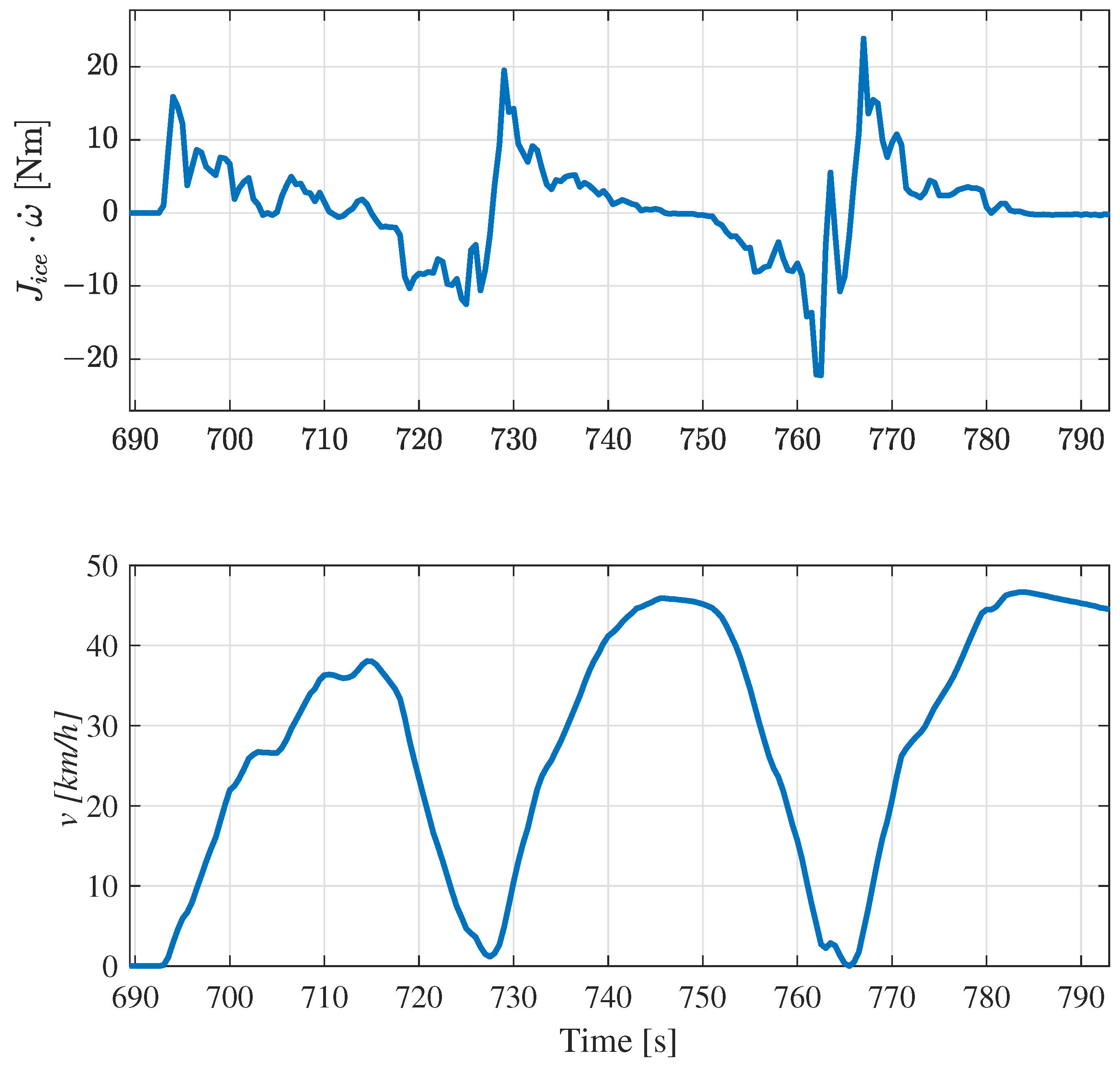
Figure 3 demonstrates the variation of 2.5 L engine inertia torque throughout the UDDS driving cycle in the engine driving mode. The torque exhibits a notably high value (ranging from −28 to 30 Nm) during acceleration and braking phases while remaining insignificant during steady motion. Engine consumption is estimated instantly using actual engine torque and angular speed, using a steady-state engine map.
To investigate the effect of inertia on fuel consumption, we simulated the model with and without engine inertia and compared the total vehicle fuel consumption for UDDS, WLTC, and US06 driving cycles. According to the data, there is an increase in vehicle fuel consumption.
Table 2 shows that the components of the engine inertia have a noticeable impact on fuel consumption. The fuel consumption required to overcome the inertia of the engine’s rotating components varies from 14 to 17 g in the considered driving cycles. This results in an additional 1.16–2% of fuel consumed due to engine inertia for one complete cycle. Cycle US06 was found to have the highest fuel usage to overcome engine inertia during the observed driving cycles, indicating that it is the most aggressive of the three cycles due to its numerous transient phases.
5. Results and Discussion
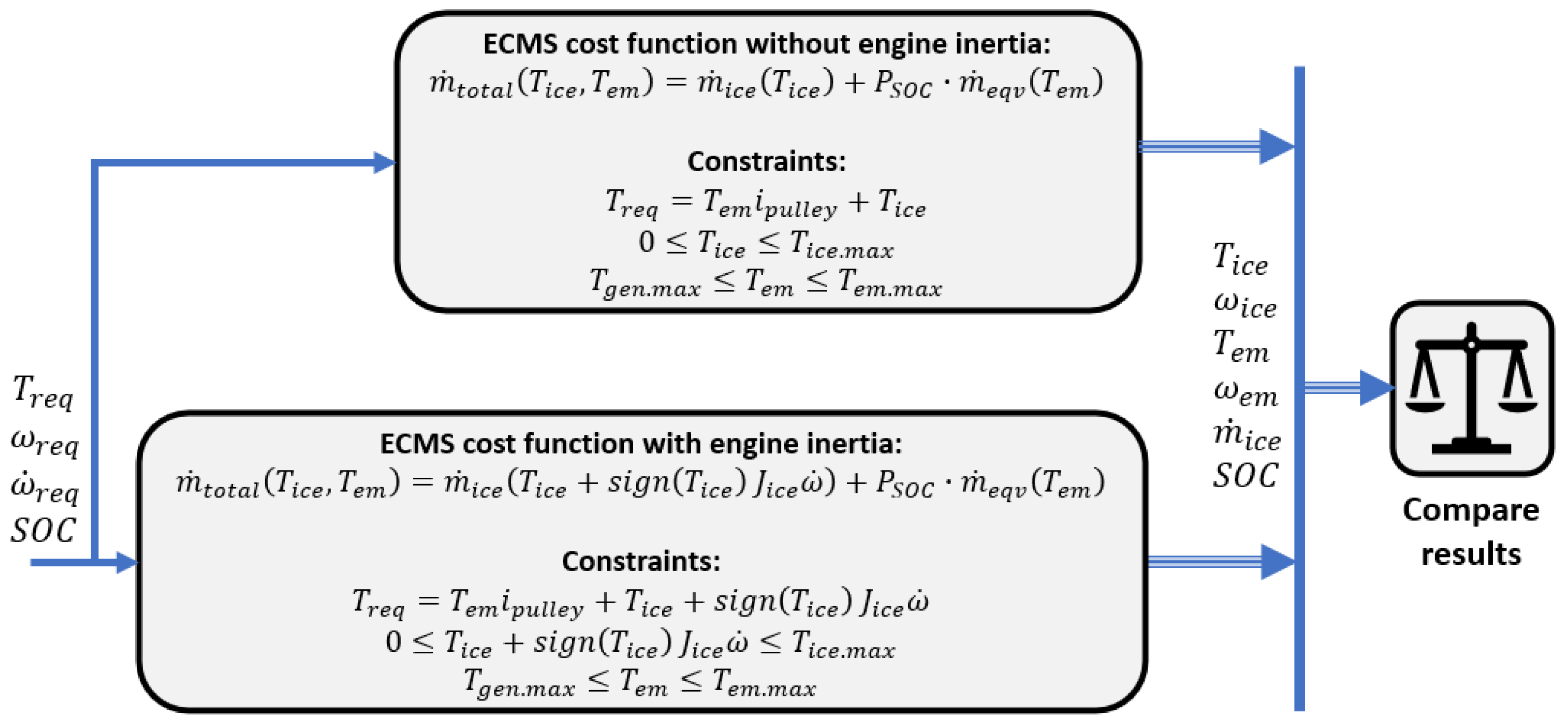
The simulations are carried out with and without the inertia effect of the engine. The results obtained under the two ECMS controllers for engine torque, EM torque, engine fuel consumption and their speeds are compared as shown in
Figure 5. A graphical illustration of a comparison of the results for UDDS cycle is given in
Figure 6.
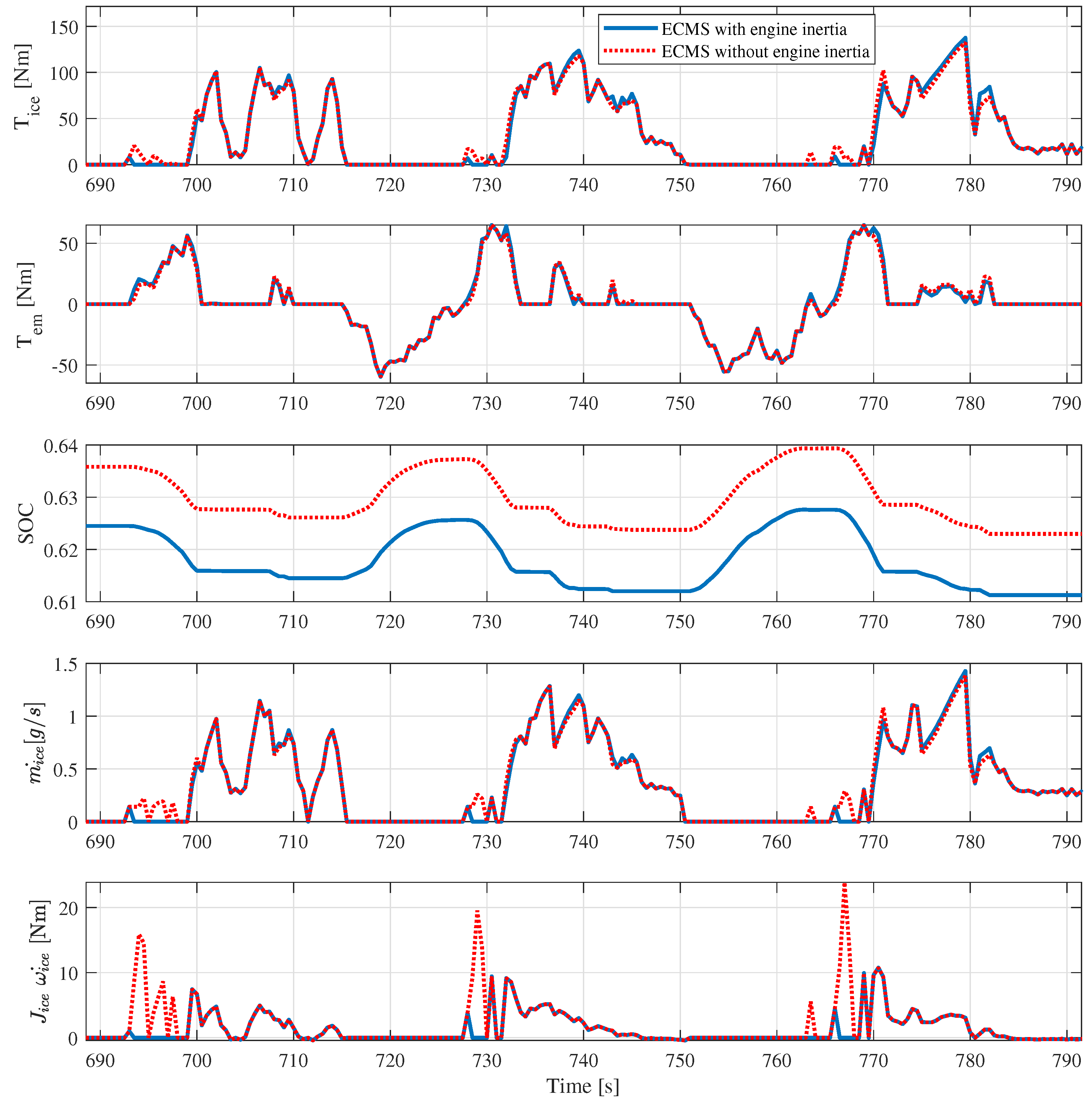
As can be observed from
Figure 6, there is a notable improvement in the stability of engine operations, when the inertia effect is included in the ECMS cost function (blue line), particularly at the peaks of the torque profile. Given that the dynamic contributions of the engine components are significant in the high-acceleration zones, it is evident that they contribute additional peaks to the engine torque. In addition, the operation of the ICE at low-torque and low-speed operating conditions where the engine inertia torque is significantly high is reduced. Typically, the ICE operates at very low efficiency at such low-torque and low-speed operating conditions. Therefore, EM operation is preferable for these ranges, as it operates at a higher efficiency. Consequently, the energy usage to overcome the inertia effect of the crankshaft and flywheel can be avoided in these ranges. The torque profile of the EM indicates that it takes on an additional portion of the required torque. This demonstrates that the engine’s stable operation is primarily achieved by reducing the inertia effects. In particular, the moments of inertia are significantly reduced at 692–698 s, 727–730 s and 760–769 s by using EM for traction. This means that the utilisation of EM power in the HEV is further optimised by incorporating the inertia effect of the engine in the controller. This leads to an improvement in the overall efficiency of the HEV system. The simulation results in terms of HEV fuel consumption demonstrate that including engine dynamics in the cost function leads to a fuel economy improvement of the vehicle. The results are summarised in
Table 3. The maximum fuel saving (1.3%) can be achieved in the UDDS cycle, as it has more acceleration phases than the other tested driving scenarios. These findings are consistent with those reported by Pam et al. [
26] in their study of the average mass model.
The incorporation of the dynamic behaviour of rotating engine components into the cost function has been demonstrated to result in a significant enhancement of the power distribution for hybrid electric vehicle (HEV) systems. The modification to the energy management of the system described above is relatively simple and does not require additional modelling of the engine characteristics, as does a transient engine model. Indeed, developing a transient model of an engine requires regression analysis on acquired data obtained in special laboratory conditions, which may not be available for every case. Consequently, the incorporation of inertial effects into the cost function is relatively easy to implement, enabling the inclusion of a part of the transient behaviour of the engine.
6. Conclusions
The initial phase of this research work involved an analysis of the impact of engine inertia on the fuel consumption of conventional vehicles. The simulation results indicated that engine inertia plays a significant role in the fuel consumption of conventional vehicles during high-acceleration phases. It was observed that the fuel consumption of the Mazda CX9 2016 can vary from 1.16% to 2% over the WLTC, UDDS and US06 driving cycles to overcome the effect of engine inertia. The largest discrepancy was observed in the UDDS driving cycle, which encompasses a greater proportion of transient and rapidly accelerated driving phases than the other cycles.
In an attempt to monitor this effect in P2 Mild HEVs, the traditional ECMS algorithm was developed as an energy management system for the vehicle. Subsequently, a novel controller was modified by incorporating the inertial effect of the engine crankshaft and flywheel into the ECMS controller algorithm. A simulation was conducted to assess the performance of the HEV under the control of the developed supervisor controllers, namely, the traditional ECMS and ECMS including inertial effects, for the same driving cycles.
The results demonstrated that incorporating the dynamics of the engine’s rotating components into the cost function enhanced the precision of the fuel consumption estimation by the controller, thereby improving the distribution of optimal power in the HEV. Furthermore, the inclusion of the inertial effect in the controller stabilises the engine operation. In particular, engine operation during startup phases with high accelerations where low torque and low speeds are required is of particular concern, as the engine operates at very low efficiency during this period. The EM power was alternatively employed during these phases. This optimises the utilisation of EM power for the HEV in charge-maintaining mode. Consequently, the HEV demonstrated fuel savings of 9, 9.1, and 4 g in the UDDS, US06, and WLTC cycles, respectively. This equates to a reduction in CO2 emissions of 2.34, 2.22 and 1.13 g/km, respectively. The greatest improvement can be observed in more challenging driving cycles as UDDS and US06 cycles.
This paper proposed optimisation of the power distribution of HEV by considering the inertia effect of engine components in the ECMS controller. Indeed, ECMS is an online controller that provides a local optimal solution. In contrast, dynamic programming provides a global optimal solution since it minimises the cost function over the entire cycle. It is anticipated that the effect of inertial components will be even more noticeable, including the dynamics of power sources in EMS, when dynamic programming is applied. Furthermore, the transient correction factor is expected to enhance the precision of the calculation of engine fuel consumption, thereby reducing fuel consumption due to engine inertia.


